WO2011068193A1 - スペースデブリ除去方法 - Google Patents
スペースデブリ除去方法 Download PDFInfo
- Publication number
- WO2011068193A1 WO2011068193A1 PCT/JP2010/071662 JP2010071662W WO2011068193A1 WO 2011068193 A1 WO2011068193 A1 WO 2011068193A1 JP 2010071662 W JP2010071662 W JP 2010071662W WO 2011068193 A1 WO2011068193 A1 WO 2011068193A1
- Authority
- WO
- WIPO (PCT)
- Prior art keywords
- space debris
- space
- earth orbit
- debris
- cylindrical body
- Prior art date
- Legal status (The legal status is an assumption and is not a legal conclusion. Google has not performed a legal analysis and makes no representation as to the accuracy of the status listed.)
- Ceased
Links
Images

Classifications
-
- B—PERFORMING OPERATIONS; TRANSPORTING
- B64—AIRCRAFT; AVIATION; COSMONAUTICS
- B64G—COSMONAUTICS; VEHICLES OR EQUIPMENT THEREFOR
- B64G1/00—Cosmonautic vehicles
- B64G1/22—Parts of, or equipment specially adapted for fitting in or to, cosmonautic vehicles
- B64G1/66—Arrangements or adaptations of apparatus or instruments, not otherwise provided for
-
- B—PERFORMING OPERATIONS; TRANSPORTING
- B64—AIRCRAFT; AVIATION; COSMONAUTICS
- B64G—COSMONAUTICS; VEHICLES OR EQUIPMENT THEREFOR
- B64G1/00—Cosmonautic vehicles
- B64G1/22—Parts of, or equipment specially adapted for fitting in or to, cosmonautic vehicles
- B64G1/62—Systems for re-entry into the earth's atmosphere; Retarding or landing devices
-
- B—PERFORMING OPERATIONS; TRANSPORTING
- B64—AIRCRAFT; AVIATION; COSMONAUTICS
- B64G—COSMONAUTICS; VEHICLES OR EQUIPMENT THEREFOR
- B64G1/00—Cosmonautic vehicles
- B64G1/10—Artificial satellites; Systems of such satellites; Interplanetary vehicles
- B64G1/1078—Maintenance satellites
- B64G1/1081—Maintenance satellites for debris removal
-
- B—PERFORMING OPERATIONS; TRANSPORTING
- B64—AIRCRAFT; AVIATION; COSMONAUTICS
- B64G—COSMONAUTICS; VEHICLES OR EQUIPMENT THEREFOR
- B64G1/00—Cosmonautic vehicles
- B64G1/22—Parts of, or equipment specially adapted for fitting in or to, cosmonautic vehicles
- B64G1/24—Guiding or controlling apparatus, e.g. for attitude control
- B64G1/242—Orbits and trajectories
-
- B—PERFORMING OPERATIONS; TRANSPORTING
- B64—AIRCRAFT; AVIATION; COSMONAUTICS
- B64G—COSMONAUTICS; VEHICLES OR EQUIPMENT THEREFOR
- B64G1/00—Cosmonautic vehicles
- B64G1/22—Parts of, or equipment specially adapted for fitting in or to, cosmonautic vehicles
- B64G1/24—Guiding or controlling apparatus, e.g. for attitude control
- B64G1/34—Guiding or controlling apparatus, e.g. for attitude control using gravity gradient
-
- B—PERFORMING OPERATIONS; TRANSPORTING
- B64—AIRCRAFT; AVIATION; COSMONAUTICS
- B64G—COSMONAUTICS; VEHICLES OR EQUIPMENT THEREFOR
- B64G1/00—Cosmonautic vehicles
- B64G1/22—Parts of, or equipment specially adapted for fitting in or to, cosmonautic vehicles
- B64G1/52—Protection, safety or emergency devices; Survival aids
- B64G1/56—Protection against meteoroids or space debris
Definitions
- the present invention relates to a method for removing space debris on earth orbit.
- Space debris is an artifact that orbits the earth orbit without being used.
- spacecraft artificial satellites, space stations, space shuttles, etc.
- spacecraft artificial satellites, space stations, space shuttles, etc.
- debris generated during the separation of multistage rockets space flight
- the tools, etc. dropped by the craftsman during the extravehicular activity become space debris.
- fine debris generated when the space debris collides and is crushed is also included in the space debris. Therefore, there are various types of space debris.
- Such space debris may collide with an operating spacecraft that is in an orbit around the Earth that intersects the Earth's orbit, which is an obstacle to the operation of the spacecraft.
- space debris with a diameter of more than 10 cm
- the presence of the space debris is captured in advance with a radar, etc. from the ground, and then retreated to the spacecraft (orbit change, attitude change, occupant evacuation, etc.) Can take action.
- small space debris with a diameter of 10 cm or less is difficult to capture from the ground, so it is practically impossible to cause the spacecraft to evacuate.
- the orbital speed of the crushed space debris on the earth orbit may be faster than the orbital speed of the space debris before pulverization. If the circulation speed of the space debris increases, the space debris cannot be easily dropped by the air drag. Therefore, the pulverization of the space debris as in the prior art described above has a risk of unintentionally increasing the space debris due to the unrealized fall of the space debris with an increased circulation speed.
- the present invention has been made in view of the above circumstances, and an object of the present invention is to provide a space debris removal method capable of removing space debris on the earth orbit without crushing.
- One aspect of the present invention is a method for removing space debris on an earth orbit, wherein a space area having a greater resistance than the atmosphere on the earth orbit is provided on the earth orbit.
- the space debris removal method of decelerating the space debris passing through the space region by the resistance force of the space region and dropping the decelerated space debris from the earth orbit.
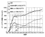
- FIG. 1 is a graph showing the current state of space debris and the future transition.
- FIG. 2 is a conceptual diagram showing a first embodiment of a space debris removal method according to the present invention.
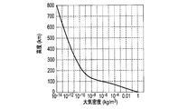
- FIG. 3 is a graph showing an exponential function model which is an example of an atmospheric density model according to altitude.
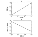
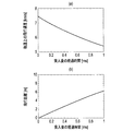
- FIG. 4 is a graph showing the correlation between the mass and the diameter of the aluminum alloy sphere and the correlation between the area mass ratio and the diameter.
- (A) is a graph showing the correlation between the mass and diameter of an aluminum alloy sphere having a density of 2.77 g / cm 3
- (b) is a graph showing the correlation between the area mass ratio of the aluminum alloy sphere and the diameter. It is.
- FIG. 1 is a graph showing the current state of space debris and the future transition.
- FIG. 2 is a conceptual diagram showing a first embodiment of a space debris removal method according to the present invention.
- FIG. 3 is a graph showing an exponential function model which is an example of an atmospheric density model according to altitude.
- FIG. 5 is a graph showing the orbital life of an aluminum alloy sphere having a diameter of 1 cm.
- FIG. 6 is a graph showing the flight speed of space debris according to altitude.
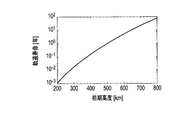
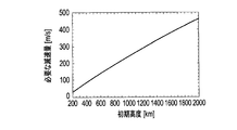
- FIG. 7 is a graph showing the correlation between the amount of deceleration of the aluminum alloy sphere necessary for lowering the near altitude of the earth orbit around which the 1 cm diameter aluminum alloy sphere orbits to 90 km and the initial altitude of the earth orbit.
- FIG. 8 is a graph showing the speed history and flight (movement) distance of an aluminum alloy ball that has entered the airgel.
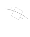
- FIG. 9 is a conceptual diagram showing a second embodiment of the space debris removal method according to the present invention.
- Figure 1 is a graph showing the transition of the number of space debris from 1957, when Sputnik 1 was launched, to the future (Source: Liou, J.-C., Johnson N. L., PLANETARY SCIENCE : Risks in Space from Orbiting Debris, Science, Vol.311, Issue 5759, 2006, pp.340-341.).
- the vertical axis of this graph indicates the number of space debris (space debris with a diameter of 10 cm over which can be captured from the ground by a radar or the like), and the horizontal axis indicates the year.
- the part up to January 1, 2006 is an actual measurement value, and the subsequent part is an estimated value.
- this estimated value is due to the launch of spacecraft (artificial satellites, space stations, space shuttles, etc.) after 2006, and the blasting of spacecraft (missiles such as missiles and the spacecraft itself) It is a value when it is assumed that no explosion occurs.
- the thin line in FIG. 1 is debris generated by a collision
- the broken line is a complete spacecraft and debris generated by its operation (falling tools, etc.)
- the alternate long and short dash line is debris generated by the blasting of the spacecraft
- the thick line is Each of these is shown.
- the number of space debris generated by collision is balanced with the number of space debris falling and disappearing due to atmospheric resistance.
- the total number of space debris tends to increase naturally, with the number of space debris generated by collision exceeding the number of space debris falling and disappearing due to atmospheric resistance. Therefore, the space debris is expected to increase even if the spacecraft is not launched in the future. That is, the space environment has already reached an unstable state, and since spacecrafts are actually being launched at present, it seems that space debris is actually increasing.
- FIG. 2 is a conceptual diagram showing a first embodiment of the space debris removal method according to the present invention.
- a hollow cylindrical body (tubular body) 1 is disposed on the earth orbit around which space debris (not shown) to be removed circulates.
- the cylindrical body 1 has a frame 1a and a speed reducing material 1b (space region) that is stretched around the frame 1a and constitutes the peripheral surface of the cylindrical body 1.
- the deceleration material 1b has a higher density (mass per unit volume) than the atmosphere at the altitude of the earth orbit where the cylindrical body 1 is disposed. Therefore, when the space debris passes through the inside of the deceleration material 1b, a larger frictional force than the atmosphere at the altitude can be applied to the space debris.
- a relatively low density material is used for the deceleration material 1b. This low-density material has a density and strength that allows the space debris to be removed to enter the interior in a substantially non-destructive manner when incident at an assumed incident speed.
- the low-density material for example, a foam material (eg, polyimide foam material), an airgel (eg, silica airgel), a foil stack, or the like can be used.
- a foil stack is a stack of metal or plastic foils.
- the peripheral surface of the cylindrical body 1 may be formed of an integrally formed speed reducing material 1b, and a plurality of speed reducing materials 1b divided in the circumferential direction or the axial direction of the cylindrical body 1 may be You may comprise by arranging along 1 surrounding surface.
- the frame 1a is not particularly limited as long as the speed reducing material 1b is stretched as the peripheral surface of the cylindrical body 1.
- the truss material fixed to the inner peripheral surface of the integrally formed speed reducing material 1b Alternatively, it can be composed of a frame material surrounding the divided moderator materials 1b and a beam material connecting the frame materials.
- the cylindrical body 1 having the above-described configuration is formed with the dimension in the central axis direction larger than the diameter.
- the cylindrical body 1 having such a shape is arranged on the earth orbit in a posture in which one opening end faces the earth E by the action of the gravity gradient. Therefore, the space debris that orbits the earth orbit different from the earth orbit of the cylinder 1 at the same altitude as the earth orbit of the cylinder 1 has its own earth orbit intersecting the earth orbit of the cylinder 1. In this point, the cylindrical body 1 passes in the radial direction (or a direction parallel to the radial direction).
- the space debris passes through the cylindrical body 1 in a direction intersecting with a straight line connecting both opening ends of the cylindrical body 1, and at that time, the space debris is decelerated at two locations spaced in the circumferential direction on the circumferential surface of the cylindrical body 1. It will pass through the material 1b.
- the deceleration material 1b of the cylindrical body 1 allows the one space debris to pass through in a substantially non-destructive manner when a certain space debris enters, and the friction force is applied to the one space debris during the passage. , The thickness of the single space debris can be reduced.
- the appropriate thickness of the deceleration material 1b can be obtained, for example, by performing the following examination.
- the aluminum alloy sphere orbits on a circular orbit in a two-dimensional plane, and that the perturbation acting on the aluminum alloy sphere during the orbit is only atmospheric resistance.
- the atmospheric density in the Earth's orbit in which the cylindrical body 1 is arranged is the exponential function model in Fig. 3 showing the atmospheric density model according to altitude (Source: David A. Vallado, "Fundamentals of Astrodynamics and Applications, 2nd Edition," pp. 532-534.).
- the relationship between the diameter and the mass of the aluminum alloy sphere having the density described above has a correlation shown in the graph of FIG. According to this graph, for example, the mass of an aluminum alloy sphere having a diameter of 1 cm is 1.45 g. Moreover, the area mass ratio of the aluminum alloy ball
- FIG. 5 is a graph showing the orbital life of an aluminum alloy sphere having a diameter of 1 cm.
- the orbital life referred to here is the number of years required for an aluminum alloy ball having a diameter of 1 cm to fall and disappear from the earth orbit.
- an aluminum alloy sphere with a diameter of 1 cm orbits an earth orbit at an altitude of 800 km, which takes about 100 years until it falls and disappears from the earth orbit and is naturally purified. To do.
- FIG. 6 is a graph showing the flight speed of space debris by altitude. As shown in FIG. 6, when the space debris breaks an altitude of 100 km, the flight speed drops rapidly and falls into the atmosphere. Space debris that falls into the atmosphere burns and disappears. Therefore, it can be evaluated that the space debris has dropped and disappeared when the altitude is lowered to 90 km.
- FIG. 8A is a graph showing the speed history of an aluminum alloy ball having a diameter of 1 cm that has entered the airgel over 1 ms from the time of entry
- FIG. 8B is a flight after the aluminum alloy ball has entered the airgel ( It is a graph which shows distance for 1 ms from rushing.
- the time taken for the aluminum alloy ball having a diameter of 1 cm to enter the airgel and decelerate by 200 m / s is about 0.1 ms.
- the distance that an aluminum alloy ball having a diameter of 1 cm enters the airgel and flies (moves) in 0.1 ms is less than 1 m.
- the thickness of the deceleration material 1b specifies the diameter and mass (density, area / mass ratio) of the space debris to be removed and the altitude of the earth orbit, and the near-point altitude of the earth orbit of the space debris.
- the amount of deceleration required to reduce the speed to 90 km is obtained, and the thickness of the space debris passing through the deceleration material 1b may be set to a thickness that can be reduced by that amount.
- the space debris passes through the cylindrical body 1 in the radial direction, the space debris passes through the deceleration material 1b at two locations. Therefore, in determining the thickness of the deceleration material 1b, it is necessary to take this point into account (a point where space debris passes through the deceleration material 1b twice).
- a cylinder using a low-density material having a higher density than the atmosphere at the altitude of the earth orbit around which the space debris to be removed orbits as the deceleration material 1b.
- the body 1 is arranged, and the space debris is decelerated by applying a frictional force to the space debris during the passage of the low density material (from the time when the space debris enters the deceleration material 1b until it escapes).
- the embodiment in the case of removing space debris from the track has been described.
- a space region having a greater resistance than the atmosphere at the altitude of the earth orbit around which the space debris to be removed is circulating is provided, and the space debris passes through the space region (the space debris is It is an example of the space debris removal method of the present invention in which the space debris is decelerated by the resistance force of the space region until the space debris is removed from the earth orbit during the period from entering the space region to escaping.
- space region means a three-dimensional finite region
- “resistance force” means that when an object on the earth orbit passes through the space region, It means the force (braking force) that acts to reduce the velocity component in the earth orbit direction.
- the spatial region having a large resistance force means a spatial region in which a larger braking force can be applied to an object passing therethrough.
- the resistance force for decelerating the space debris that passes through the space region is not limited to the friction force.
- the electromagnetic force received from a strong magnetic field is used as the resistance force for decelerating the space debris that passes through the space region. It can also be used.
- a space region with a magnetic field stronger than the atmospheric magnetic field at the altitude of the earth orbit where the space debris to be removed circulates is provided, and the electromagnetic acting on the space debris when passing through the space region of this strong magnetic field
- the space debris may be decelerated by force to remove the space debris from the earth orbit.
- FIG. 9 is a conceptual diagram showing a second embodiment of the space debris removal method according to the present invention.
- a space region 11 of a magnetic field stronger than the atmosphere at an altitude where the earth orbit exists is provided on the earth orbit around which the space debris to be removed orbits.
- the magnetic field in the space region 11 is a current having a magnitude and direction suitable for forming a required strong magnetic field in an object that circulates on a different earth orbit at the same altitude as the earth orbit of the space debris to be removed. It can be realized by flowing.
- the strong magnetic field in the spatial region 11 preferably includes a vector component in which the magnetic field vector is orthogonal to the earth orbit of space debris.
- the space debris that orbits the earth orbit different from the earth orbit of the space region 11 at the same altitude as the earth orbit of the space region 11 has its own earth orbit. It passes through the spatial region 11 at a point that intersects the trajectory. At that time, charged particles in the space debris receive a Lorentz force from the magnetic field in the space region 11 in a direction different from the orbiting direction of the earth (ideally, a direction approaching the earth), or the conductor in the space debris is electromagnetic. Under the force of the interaction between the induced current and the magnetic field generated by the induction, the flight speed of the space debris on the earth orbit is reduced (possibly with a change in the flight direction).
- the diameter and mass (density, area / mass ratio) of the space debris to be removed by the removal method of the present embodiment is specified, and accordingly, it is necessary for the near-point altitude of the earth orbit to fall to 90 km. It is necessary to obtain an electromagnetic force suitable for decelerating the space debris to a certain speed, and to generate the magnetic field strength and the magnetic field in the space region 11 so that the electromagnetic force acts on the space debris passing through the space region 11. What is necessary is just to determine the magnitude
- the flight speed of the space debris on the earth orbit is reduced until the near-point altitude decreases to 90 km due to frictional force or electromagnetic force. Since the vehicle is decelerated, the space debris can be removed from the orbit around the earth without pulverizing the space debris, which may increase the orbital speed and possibly cause the fall.
- the cylindrical body 1 in which the deceleration material 1b is stretched in a cylindrical shape on the frame 1a is used.
- the space debris can be efficiently decelerated by the frictional force received from the deceleration material 1b.
- the cylindrical body 1 was used in 1st Embodiment mentioned above, it may replace with a cylindrical body and you may make it use the cylinder whose cross section is a (regular) polyhedron.
- the decelerating material 1b is not necessarily a hollow body (a cylindrical body as in the first embodiment or a cylinder whose cross section is a (normal) polyhedron. ) Is not necessary. That is, it may be a solid body such as a columnar shape or a prismatic shape of a (regular) polyhedron.
- the space debris removal method of the present invention is particularly useful when a space debris of 10 cm or less that cannot be captured by a radar from the ground or the like is to be removed, but when a large space debris exceeding 10 cm is to be removed. Needless to say, the present invention is useful.
- the space debris removal method of the present invention is particularly suitable for a cylindrical body 1 or a space region 11 on a low earth orbit at an altitude of less than 2000 km where atmospheric resistance (air drag) can be expected to act on the space debris. It is effective to arrange and implement a space region having a greater resistance than the atmosphere in low earth orbit. However, it is of course possible to carry out the space debris removal method of the present invention by placing a space region having a greater resistance than the atmosphere on the earth orbit at an altitude of 2000 km or higher.
- one aspect of the present invention is a method for removing space debris on an earth orbit, and a space region having a greater resistance than the atmosphere on the earth orbit on the earth orbit.
- the space debris removing method is provided, wherein the space debris passing through the space region is decelerated by the resistance force of the space region, and the decelerated space debris is dropped from the earth orbit.
- the space debris removal method when the space debris on the earth orbit passes through a space area provided on the earth orbit having a greater resistance than the atmosphere on the earth orbit, the space area Decelerate by receiving resistance. By this deceleration, the near-point altitude of the earth orbit where the space debris flies gradually approaches the earth, and eventually the space debris falls to an altitude suitable for burning by re-entry into the atmosphere (for example, 90 km above the ground).
- the space debris is decelerated so as to fall to an altitude suitable for burning by re-entry into the atmosphere due to the resistance force when passing through the space region. For this reason, it is possible to remove the space debris from the earth orbit without pulverizing the space debris, which may increase the orbital velocity and cause the drop to be unrealized.
- the space region may be a space region having a higher density than the atmosphere on the earth orbit, and the space debris passing through the space region may be decelerated by a frictional force.
- the space region is constituted by a peripheral surface of a cylindrical body with one opening end facing the earth, and the space debris intersects a straight line connecting the two opening ends of the cylindrical body. You may make it pass a cylinder in a direction.
- the space debris passes through the cylinder in a direction intersecting with the straight line connecting the two open ends of the cylinder, the space debris passes through two locations on the opposing peripheral surfaces of the cylinder. That is, each time the space debris passes through the cylindrical body, it passes through the space area twice. Therefore, the space debris can be efficiently decelerated by the friction force of the space area and dropped from the earth orbit. Can be executed.
- the cylindrical body having an area-mass ratio that drops over a predetermined period from the earth orbit may be arranged on the earth orbit.
- the cylindrical body arranged in the earth orbit drops from the earth orbit over a predetermined period (for example, 25 years) while gradually approaching the near point altitude to the earth. For this reason, the altitude of the orbit around which the cylinder circulates gradually decreases over a predetermined period. During this period, the space debris decelerates and falls from the orbit around the earth in the range of altitude around which the cylinder circulates. Can be executed.
- the cylinder falls from the earth orbit where it was originally placed after a predetermined period, it can be removed so that the cylinder itself does not remain on the earth orbit as space debris.
- the space debris removal method when the space debris on the earth orbit passes through a space area having a greater resistance than the atmosphere on the earth orbit, the space debris receives a resistance force from the space area. Thereby, the near point altitude of the earth orbit of the space debris decreases (or the descent of the near point altitude is promoted), and eventually the space debris falls to an altitude suitable for burning out by re-entry into the atmosphere. For this reason, the space debris can be removed from the earth orbit without pulverizing the space debris, which may increase the circulation speed and possibly cause the drop to be unrealized.
Landscapes
- Engineering & Computer Science (AREA)
- Remote Sensing (AREA)
- Aviation & Aerospace Engineering (AREA)
- Particle Accelerators (AREA)
- Physics & Mathematics (AREA)
- Elimination Of Static Electricity (AREA)
- General Physics & Mathematics (AREA)
- Astronomy & Astrophysics (AREA)
- Exposure Of Semiconductors, Excluding Electron Or Ion Beam Exposure (AREA)
- Radar, Positioning & Navigation (AREA)
- Combustion & Propulsion (AREA)
- Chemical & Material Sciences (AREA)
- Cleaning In General (AREA)
- Drilling And Exploitation, And Mining Machines And Methods (AREA)
Abstract
地球周回軌道上のスペースデブリを除去する方法であって、地球周回軌道上に、該地球周回軌道上における大気よりも抵抗力が大きい空間領域を設け、該空間領域を通過するスペースデブリを抵抗力により減速させ、減速させたスペースデブリを地球周回軌道上から落下させるスペースデブリ除去方法。
Description
本発明は、地球周回軌道上のスペースデブリを除去する方法に関する。
スペースデブリは、運用されることなく地球周回軌道上を周回している人工物である。例えば、寿命や事故、故障により運用を終えた宇宙機(人工衛星や宇宙ステーション、スペースシャトル等)、人工衛星の打ち上げに使用したロケットの本体及び部品、多段ロケットの切り離し時に生じた破片、宇宙飛行士が船外活動で落とした工具等がスペースデブリとなる。また、スペースデブリどうしが衝突して粉砕されることで生じた微細デブリも、スペースデブリに含まれる。したがって、スペースデブリには大小様々なものがある。
このようなスペースデブリは、その地球周回軌道と交差する地球周回軌道上にある運用中の宇宙機に衝突する恐れがあり、宇宙機にとって運用の障害となる。直径が10cmを超える大きな(完全体の宇宙機を含む)スペースデブリについては、地上からレーダ等でその存在を事前に捕捉して、宇宙機に退避行動(軌道変更、姿勢変更、乗員退避等)の措置を執らせることができる。しかし、直径が10cm以下の小さなスペースデブリについては、地上からの捕捉が困難であるため、宇宙機に退避行動を執らせることが事実上不可能である。
そこで、スペースデブリに対する対策として、宇宙機の進行方向前方に薄肉の金属板を配置し、この金属板に、宇宙機に向かって飛来するスペースデブリを衝突、貫通させ、スペースデブリを細かく粉砕する技術が提案されている。この技術では、粉砕前のスペースデブリに比べて面積質量比(平均断面積/質量)が増加した粉砕後のスペースデブリを、エアードラグ(大気抵抗)により地球周回軌道上から落下させるようにしている(特許文献1参照)。
しかし、粉砕されたスペースデブリの地球周回軌道上における周回速度は、粉砕前のスペースデブリの周回速度より速くなることもある。スペースデブリの周回速度が速くなれば、その分だけエアードラグによるスペースデブリの落下も容易でなくなる。したがって、上述した従来技術のようなスペースデブリの粉砕は、周回速度が増加したスペースデブリの落下不実現により、図らずもスペースデブリを増加させる結果を招く恐れをはらんでいる。
本発明は前記事情に鑑みなされたもので、本発明の目的は、破砕を伴わずに地球周回軌道上のスペースデブリの除去を行うことができるスペースデブリ除去方法を提供することにある。
本発明の一態様は、地球周回軌道上のスペースデブリを除去する方法であって、前記地球周回軌道上に、該地球周回軌道上における大気よりも抵抗力が大きい空間領域を設け、前記空間領域を通過するスペースデブリを前記空間領域の抵抗力により減速させ、当該減速させたスペースデブリを前記地球周回軌道上から落下させるスペースデブリ除去方法である。
以下、本発明の実施形態について図面を参照しながら説明する。
まず、本発明の実施形態を具体的に説明するのに先立って、スペースデブリの現状と今後について説明する。図1は、スペースデブリの数の推移を、スプートニク1号の打ち上げ時である1957年から将来に亘って示すグラフである(出典、Liou, J.-C., Johnson N. L., PLANETARY SCIENCE: Risks in Space from Orbiting Debris, Science, Vol.311, Issue 5759, 2006, pp.340-341. )。このグラフの縦軸はスペースデブリ(地上からレーダ等によって捕捉できる直径10cmオーバーの大きいスペースデブリ)の個数、横軸は西暦年数を示す。2006年1月1日までの部分は実測値、それ以降の部分は推定値である。但し、この推定値は、2006年以降に宇宙機(人工衛星や宇宙ステーション、スペースシャトル等)の打ち上げを行わず、かつ、宇宙機の爆破(ミサイル等による人為的な爆破や宇宙機自身に起因して発生する爆破)が発生しないものと仮定した場合の値である。また、図1中の細線は、衝突によって発生するデブリ、破線は、完全体の宇宙機とその運用によって生じるデブリ(落下工具等)、一点鎖線は、宇宙機の爆破によって発生するデブリ、太線はそれらの合計をそれぞれ示している。
図1のグラフに示す研究結果では、2055年までは、衝突で発生するスペースデブリの数が、大気抵抗で落下・消滅するスペースデブリの数と釣り合って、スペースデブリの総数が平衡状態を保つが、それ以降は、衝突で発生するスペースデブリの数が、大気抵抗で落下・消滅するスペースデブリの数を上回って、スペースデブリの総数が自然増する傾向にある。したがって、スペースデブリは、宇宙機が今後打ち上げられなくても増加することが見込まれる。即ち、宇宙環境は既に不安定な状態を迎えており、実際には宇宙機の打ち上げを現在も行っていることから、現実には現在もスペースデブリが増加しているものと思われる。
以上のような事情により、スペースデブリを地球周回軌道上から除去することは、宇宙環境の浄化と宇宙機の安定した運用を図る上で、非常に重要であることが分かる。
次に、本発明によるスペースデブリ除去方法の実施形態を、以下に具体的に説明する。
図2は本発明によるスペースデブリ除去方法の第1実施形態を示す概念図である。本実施形態では、除去対象のスペースデブリ(図示せず)が周回する地球周回軌道上に、中空の円筒体(筒体)1を配置している。
図2は本発明によるスペースデブリ除去方法の第1実施形態を示す概念図である。本実施形態では、除去対象のスペースデブリ(図示せず)が周回する地球周回軌道上に、中空の円筒体(筒体)1を配置している。
円筒体1は、フレーム1aと、このフレーム1aに張設されて円筒体1の周面を構成する減速材料1b(空間領域)とを有している。減速材料1bは、円筒体1を配置する地球周回軌道の高度における大気よりも高い密度(単位体積あたりの質量)を有している。そのため減速材料1bは、その内部をスペースデブリが通過する際に、当該高度における大気よりも大きな摩擦力をスペースデブリに作用させることができる。この減速材料1bには、比較的低密度の材料が用いられる。この低密度材料は、除去対象となるスペースデブリが、想定される入射速度で入射したとき、これを略非破壊で内部に進入させることが可能な密度および強度を有する。低密度材料としては、例えば、フォーム材(例:ポリイミドフォーム材)、エアロジェル(例:シリカエアロジェル)、フォイルスタック等を使用することができる。フォイルスタックとは、金属やプラスチックのフォイルを多層に重ねたものである。なお、円筒体1の周面は、一体的に形成された減速材料1bで構成してもよく、また、円筒体1の周方向または軸方向に分割された複数の減速材料1bを、円筒体1の周面に沿って並設することで構成してもよい。また、フレーム1aは、減速材料1bを円筒体1の周面として張設するものであれば特に限定されず、例えば、一体的に形成された減速材料1bの内周面に固定されたトラス材、あるいは、分割された各減速材料1bの周囲を囲む枠材および各枠材を連結するビーム材で構成することができる。
上述した構成の円筒体1は、直径よりも中心軸方向の寸法を大きくして形成されている。このような形状の円筒体1は、重力傾斜の作用によって、一方の開口端が地球Eを指向する姿勢で地球周回軌道上に配置される。したがって、円筒体1の地球周回軌道と同じ高度の、円筒体1の地球周回軌道とは異なる地球周回軌道上を周回するスペースデブリは、自身の地球周回軌道が円筒体1の地球周回軌道と交差する点において、円筒体1をその径方向(または当該径方向に平行な方向)に通過する。つまり、スペースデブリは、円筒体1の両開口端どうしを結ぶ直線と交差する方向で円筒体1を通過し、その際、円筒体1の周面における周方向に間隔をおいた2箇所において減速材料1bを通過することになる。
円筒体1の減速材料1bは、ある1個スペースデブリが入射したとき、当該1個のスペースデブリを略非破壊のまま通過させ、かつその通過の際に、当該1個のスペースデブリに摩擦力を作用させることによって、当該1個のスペースデブリの飛行速度を減速させることができる厚さに形成される。減速材料1bの適切な厚さは、例えば、以下の検討を行うことで求めることができる。
まず、除去対象となるスペースデブリの直径や質量(密度、面積質量比)を特定する。ここでは、スペースデブリが、密度=2.77g/cm3のアルミニウム合金による直径1cmの球体であるものと仮定する。また、このアルミニウム合金球は、2次元平面内の円軌道上を周回しているものとし、周回中にアルミニウム合金球に働く摂動力は大気抵抗のみであるものとする。なお、円筒体1を配置する地球周回軌道における大気密度は、高度による大気密度モデルを示す図3の指数関数モデル(出典、David A. Vallado, "Fundamentals of Astrodynamics and Applications, 2nd Edition," pp.532-534.)により定めることとする。さらに、減速材料1bには、密度=1.9kg/m3のエアロジェルを用いるものとする。アルミニウム合金球がエアロジェル中を通過する際に受ける摩擦抵抗(摩擦力)は、エアロジェルと同じ密度の大気をアルミニウム合金球が通過する際に受ける空気抵抗と同じであるものと仮定する。
上述した密度を有するアルミニウム合金球の直径と質量との関係は、図4(a)のグラフに示す相関を有している。このグラフによれば、例えば直径1cmのアルミニウム合金球の質量は1.45gとなる。また、直径1cmで1.45gの質量を有するアルミニウム合金球の面積質量比は、直径との間に図4(b)のグラフに示す相関を有している。このグラフによれば、直径1cmのアルミニウム合金球の軌道計算に必要なパラメータである面積質量比は、0.054m2/kgとなる。
図5は、直径1cmのアルミニウム合金球の軌道寿命を示すグラフである。ここで言う軌道寿命とは、直径1cmのアルミニウム合金球が地球周回軌道から落下・消滅するまでにかかる時間を年数で表したものである。減速材料1bの厚さの検討に当たっては、直径1cmのアルミニウム合金球が、地球周回軌道から落下・消滅して自然浄化されるまでに100年ほど要する高度800kmの地球周回軌道を周回する場合を想定する。
図6は、高度によるスペースデブリの飛行速度を示すグラフである。この図6に示すように、スペースデブリは、高度100kmを割ると飛行速度が急激に下がり、大気圏に落下する。大気圏に落下したスペースデブリは燃焼して消滅する。したがって、スペースデブリは、高度が90kmまで下がれば落下・消滅したものと評価することができる。
そこで、直径1cmのアルミニウム合金球が周回する地球周回軌道の近点高度を90kmに下げるのに必要なアルミニウム合金球の減速量を考える。図7は、必要な減速量と地球周回軌道の初期高度との相関関係を示すグラフである。図7に示すように、アルミニウム合金球の地球周回軌道が初期高度=800kmであるとすると、地球周回軌道の近点高度を90kmに下げるのに必要なアルミニウム合金球の減速量は約200m/sである。
図8(a)は、エアロジェルに突入した直径1cmのアルミニウム合金球の速度履歴を突入から1ms分に亘って示すグラフ、図8(b)はそのアルミニウム合金球のエアロジェル突入後の飛行(移動)距離を突入から1ms分に亘って示すグラフである。図8(a)に示すように、直径1cmのアルミニウム合金球がエアロジェルに突入して200m/s減速されるまでにかかる時間は0.1ms程である。また、図8(b)に示すように、直径1cmのアルミニウム合金球がエアロジェルに突入して0.1msの間に飛行(移動)する距離は、1m未満である。
したがって、800kmの高度で周回する直径1cmのアルミニウム合金球は、1mの厚さのエアロジェルを通過すると、通過時にエアロジェルから受ける摩擦力により、地球周回軌道の近点高度が90kmに落下するのに必要な速度まで減速されることになる。
以上の通り、減速材料1bの厚さは、除去対象となるスペースデブリの直径や質量(密度、面積質量比)および地球周回軌道の高度を特定し、そのスペースデブリの地球周回軌道の近点高度を90kmに下げるのに必要な減速量を求め、減速材料1bを通過するスペースデブリをその減速量だけ減速させることができる厚さに設定すればよい。なお、本実施形態では、スペースデブリが円筒体1をその径方向に通過するので、スペースデブリは減速材料1bを2箇所通過することになる。したがって、減速材料1bの厚さを決定するにあたっては、この点(スペースデブリが減速材料1bを2回通過する点)を踏まえておく必要がある。
なお、近年では、スペースデブリの増加を防ぐために、地球周回軌道上に打ち上げた宇宙機を一定期間(例えば25年)後に地球周回軌道上から除去する(例えば地上へ落下させる)ルール作りが検討されている。そこで、地球周回軌道上に配置する円筒体1の面積質量比を適切に選択し、一定期間後に近点高度が90kmまで落下するように構成した円筒体1を地球周回軌道上に配置して、本発明を実施するようにしてもよい。そのようにすれば、一定期間に亘って徐々に近点高度を下げながら地球の周りを周回する円筒体1によって、円筒体1が当初配置された高度以下の地球低軌道上のスペースデブリを順次除去し、かつ、円筒体1自身も地球周回軌道上から除去することができる。
以上に、除去対象となるスペースデブリが周回する地球周回軌道の高度に、その高度における大気よりも高い密度の低密度材料(フォーム材、エアロジェル、フォイルスタック等)を減速材料1bとして用いた円筒体1を配置し、低密度材料の通過時(スペースデブリが減速材料1bに進入してから脱出するまでの間)にスペースデブリに摩擦力を作用させることによりスペースデブリを減速させて、地球周回軌道からスペースデブリを除去する場合の実施形態について説明した。この実施形態は、除去対象となるスペースデブリが周回する地球周回軌道の高度に、その高度における大気よりも抵抗力が大きい空間領域を設け、その空間領域をスペースデブリが通過する際(スペースデブリが当該空間領域に進入してから脱出するまでの間)に、当該空間領域の抵抗力によってスペースデブリを減速させて、地球周回軌道からスペースデブリを除去する本発明のスペースデブリ除去方法の一例である。なお、「空間領域」とは、3次元の有限な領域を意味し、「抵抗力」とは、当該空間領域の中を地球周回軌道上の物体が通過する際に、その物体に対して、その地球周回軌道方向の速度成分を減少させるように作用する力(制動力)を意味する。従って、抵抗力が大きい空間領域とは、その中を通過する物体に対してより大きな制動力を作用させることのできる空間領域を意味する。
即ち、空間領域を通過するスペースデブリを減速させるための抵抗力は、摩擦力だけに限らず、例えば、強い磁場から受ける電磁力を、空間領域を通過するスペースデブリを減速させるための抵抗力として用いることも考えられる。つまり、除去対象となるスペースデブリが周回する地球周回軌道の高度に、その高度における大気の磁場よりも強い磁場の空間領域を設け、この強い磁場の空間領域を通過する際にスペースデブリに働く電磁力により、スペースデブリを減速させて、地球周回軌道からスペースデブリを除去するようにしてもよい。
図9は本発明によるスペースデブリ除去方法の第2実施形態を示す概念図である。本実施形態では、除去対象のスペースデブリが周回する地球周回軌道上に、その地球周回軌道が存在する高度における大気よりも強い磁場の空間領域11を設けている。この空間領域11の磁場は、除去対象のスペースデブリの地球周回軌道と同じ高度の、異なる地球周回軌道上を周回する物体において、所要の強い磁場を形成するのに適した大きさ及び方向の電流を流すことによって実現することができる。この空間領域11の強い磁場は、磁場のベクトルが、スペースデブリの地球周回軌道と直交するベクトル成分を含むことが望ましい。
本実施形態において、空間領域11の地球周回軌道と同じ高度の、空間領域11の地球周回軌道とは異なる地球周回軌道上を周回するスペースデブリは、自身の地球周回軌道が空間領域11の地球周回軌道と交差する点において、空間領域11を通過する。その際、スペースデブリ中の荷電粒子が空間領域11の磁場から地球周回軌道方向とは異なる方向(理想的には地球に接近する方向)へローレンツ力を受け、あるいは、スペースデブリ中の導体が電磁誘導によって生じる誘導電流と磁場との相互作用による力を受け、スペースデブリの地球周回軌道上の飛行速度が(場合によっては飛行方向の変化を伴って)減速されることになる。
したがって、本実施形態の除去方法により除去する対象のスペースデブリの直径や質量(密度、面積質量比)を特定し、これに応じて、地球周回軌道の近点高度が90kmに落下するのに必要な速度までスペースデブリを減速させるのに適した電磁力を求め、その電磁力が、空間領域11を通過するスペースデブリに働くように、空間領域11の磁場の強さとその磁場を作るのに必要な電流の大きさ及び方向とを決定すればよい。
以上に説明した本発明の第1及び第2実施形態に係るスペースデブリ除去方法によれば、摩擦力や電磁力により、近点高度が90kmに下がるまで地球周回軌道上におけるスペースデブリの飛行速度を減速させるので、周回速度の増加やそれによる落下不実現の恐れがあるスペースデブリの粉砕を伴わずに、スペースデブリを地球周回軌道上から除去することができる。
また、本発明の第1実施形態に係るスペースデブリ除去方法によれば、減速材料1bをフレーム1aに円筒状に張設した円筒体1を用いることから、円筒体1の通過時にスペースデブリを減速材料1bに2回通過させて、減速材料1bから受ける摩擦力によるスペースデブリの減速を効率的に実行させることができる。
なお、上述した第1実施形態では円筒体1を用いたが、円筒体に代えて、断面が(正)多面体である筒体を用いるようにしてもよい。また、減速材料1bを通過する際の摩擦力によりスペースデブリを減速させる場合に、減速材料1bは必ずしも中空体(第1実施形態のような円筒体や、断面が(正)多面体である筒体)である必要はない。つまり、円柱状や(正)多面体による角柱状のような中実体であってもよい。
そして、本発明のスペースデブリ除去方法は、地上からのレーダ等によって捕捉できない10cm以下のスペースデブリを除去対象とする場合に特に有用であるが、10cmを上回る大きなスペースデブリを除去対象とする場合にも本発明が有用であるのは言うまでもない。
また、本発明のスペースデブリ除去方法は、特に、大気抵抗(エアードラグ)がスペースデブリに作用することを期待できる、高度2000km未満の地球低軌道上に、円筒体1や空間領域11のような、地球低軌道上における大気よりも大きな抵抗力の空間領域を配置して実施すると、効果的である。しかし、高度2000km以上の地球周回軌道上に、その地球周回軌道上における大気よりも抵抗力が大きい空間領域を配置して本発明のスペースデブリ除去方法を実施することも、勿論可能である。
以上説明した通り、本発明の一態様は、地球周回軌道上のスペースデブリを除去する方法であって、前記地球周回軌道上に、該地球周回軌道上における大気よりも抵抗力が大きい空間領域を設け、前記空間領域を通過するスペースデブリを前記空間領域の抵抗力により減速させ、当該減速させたスペースデブリを前記地球周回軌道上から落下させるスペースデブリ除去方法である。
本スペースデブリ除去方法によれば、地球周回軌道上のスペースデブリが、地球周回軌道上に設けられた、地球周回軌道上における大気よりも抵抗力が大きい空間領域を通過する際に、その空間領域から抵抗力を受けて減速する。この減速によって、スペースデブリが飛行する地球周回軌道の近点高度は徐々に地球に近づき、やがて、大気圏再突入により燃え尽きさせるのに適した高度(例えば地上90km)までスペースデブリが落下する。
このように、スペースデブリは、前記空間領域通過時の抵抗力によって、大気圏再突入により燃え尽きさせるのに適した高度まで落下するように減速される。このため、周回速度の増加やそれによる落下不実現の恐れがあるスペースデブリの粉砕を伴わずに、スペースデブリを地球周回軌道上から除去することができる。
また、本スペースデブリ除去方法において、前記空間領域を、前記地球周回軌道上における大気よりも密度が高い空間領域とし、該空間領域を通過するスペースデブリを摩擦力により減速させるようにしてもよい。
このようにすれば、地球周回軌道上における大気よりも密度が高い物質を、スペースデブリが周回する地球周回軌道上に配置するだけで、スペースデブリを、前記空間領域通過時の摩擦力により、大気圏再突入により燃え尽きさせるのに適した高度まで落下するように減速させることができる。
さらに、本スペースデブリ除去方法において、前記空間領域を、一方の開口端を地球に向けた筒体の周面によって構成し、スペースデブリが、該筒体の両開口端どうしを結ぶ直線と交差する方向において、筒体を通過するようにしてもよい。
スペースデブリが、前記筒体の両開口端どうしを結ぶ直線と交差する方向において、筒体を通過すると、スペースデブリは筒体の対向する周面の2箇所を通過することになる。つまりスペースデブリは、筒体を1回通過する度に前記空間領域を2回通過するようになるので、空間領域の摩擦力によるスペースデブリの減速と地球周回軌道上からの落下とを効率的に実行することができる。
また、本スペースデブリ除去方法において、前記地球周回軌道上から所定期間を費やして落下する面積質量比の前記筒体を前記地球周回軌道上に配置するようにしてもよい。
このようにすれば、地球周回軌道上に配置した筒体が、近点高度を徐々に地球に近づけながら、所定期間(例えば25年)を費やして地球周回軌道上から落下する。このため、筒体が周回する軌道の高度は、所定期間に亘って徐々に下がることになり、その間、筒体が周回する高度の範囲において、スペースデブリの減速とそれによる地球周回軌道からの落下を実行することができる。
しかも、所定期間後には筒体が当初配置された地球周回軌道から落下するので、筒体自身がスペースデブリとして地球周回軌道上に残存しないよう除去することができる。
本出願は、2009年12月4日に出願された日本国特許願第2009-276530号に基づく優先権を主張しており、これらの出願の全内容が参照により本明細書に組み込まれる。
本発明にかかるスペースデブリ除去方法によれば、地球周回軌道上のスペースデブリが、地球周回軌道上における大気よりも抵抗力が大きい空間領域を通過する際に、該空間領域から抵抗力を受ける。これにより、スペースデブリの地球周回軌道の近点高度は下がり(または近点高度の降下が促進され)、やがて大気圏再突入により燃え尽きさせるのに適した高度までスペースデブリが落下する。このため、周回速度の増加やそれによる落下不実現の恐れがあるスペースデブリの粉砕を伴わずに、スペースデブリの地球周回軌道上からの除去を行うことができる。
1 円筒体(筒体)
1a フレーム
1b 減速材料(空間領域)
11 空間領域
E 地球
1a フレーム
1b 減速材料(空間領域)
11 空間領域
E 地球
Claims (4)
- 地球周回軌道上のスペースデブリを除去する方法であって、
前記地球周回軌道上に、該地球周回軌道上における大気よりも抵抗力が大きい空間領域を設け、
前記空間領域を通過するスペースデブリを前記空間領域の抵抗力により減速させ、
当該減速させたスペースデブリを前記地球周回軌道上から落下させる、
ことを特徴とするスペースデブリ除去方法。 - 前記空間領域を、前記地球周回軌道上における大気よりも密度が高い空間領域とし、該空間領域を通過するスペースデブリを摩擦力により減速させるようにしたことを特徴とする請求項1記載のスペースデブリ除去方法。
- 前記空間領域を、一方の開口端を地球に向けた筒体の周面によって構成し、該筒体の両開口端どうしを結ぶ直線と交差する方向において、前記スペースデブリに前記筒体を通過させるようにしたことを特徴とする請求項2記載のスペースデブリ除去方法。
- 前記地球周回軌道上から所定期間を費やして落下する面積質量比の前記筒体を前記地球周回軌道上に配置するようにしたことを特徴とする請求項3記載のスペースデブリ除去方法。
Priority Applications (3)
| Application Number | Priority Date | Filing Date | Title |
|---|---|---|---|
| EP10834643.8A EP2508430B1 (en) | 2009-12-04 | 2010-12-03 | Method for clearing space debris |
| US13/513,342 US9302789B2 (en) | 2009-12-04 | 2010-12-03 | Method for clearing space debris |
| RU2012127365/11A RU2524325C2 (ru) | 2009-12-04 | 2010-12-03 | Способ для очистки от космического мусора |
Applications Claiming Priority (2)
| Application Number | Priority Date | Filing Date | Title |
|---|---|---|---|
| JP2009-276530 | 2009-12-04 | ||
| JP2009276530A JP5755836B2 (ja) | 2009-12-04 | 2009-12-04 | スペースデブリ除去方法 |
Publications (1)
| Publication Number | Publication Date |
|---|---|
| WO2011068193A1 true WO2011068193A1 (ja) | 2011-06-09 |
Family
ID=44115039
Family Applications (1)
| Application Number | Title | Priority Date | Filing Date |
|---|---|---|---|
| PCT/JP2010/071662 Ceased WO2011068193A1 (ja) | 2009-12-04 | 2010-12-03 | スペースデブリ除去方法 |
Country Status (5)
| Country | Link |
|---|---|
| US (1) | US9302789B2 (ja) |
| EP (1) | EP2508430B1 (ja) |
| JP (1) | JP5755836B2 (ja) |
| RU (1) | RU2524325C2 (ja) |
| WO (1) | WO2011068193A1 (ja) |
Cited By (2)
| Publication number | Priority date | Publication date | Assignee | Title |
|---|---|---|---|---|
| RU2643020C1 (ru) * | 2016-09-06 | 2018-01-29 | Федеральное государственное бюджетное образовательное учреждение высшего образования "Омский государственный технический университет" | Способ проведения лётно-конструкторских испытаний автономного стыковочного модуля для очистки орбит от космического мусора |
| CN110510154A (zh) * | 2019-08-21 | 2019-11-29 | 中国科学院力学研究所 | 一种地磁蓄能低轨道空间碎片离轨投送轨姿耦合调整方法 |
Families Citing this family (16)
| Publication number | Priority date | Publication date | Assignee | Title |
|---|---|---|---|---|
| DE102010008376A1 (de) * | 2010-02-17 | 2011-08-18 | Astrium GmbH, 82024 | Vorrichtung zum Eliminieren von Weltraumschrott im Orbit |
| SG195087A1 (en) | 2011-05-24 | 2013-12-30 | Furukawa Electric Co Ltd | Superconducting element for superconducting current limiter, method for manufacturing superconducting element for superconducting current limiter, and superconducting current limiter |
| US9617017B1 (en) * | 2016-10-25 | 2017-04-11 | Marshall H. Kaplan | Apparatus and methods for orbital debris removal |
| US9714101B1 (en) * | 2016-10-25 | 2017-07-25 | Marshall H. Kaplan | Apparatus and methods for orbital debris removal |
| RU2676592C2 (ru) * | 2016-12-19 | 2019-01-09 | Акционерное общество "Научно-исследовательский институт электромеханики" (АО "НИИЭМ") | Устройство управления движением космического аппарата для очистки космоса от мусора |
| RU177015U1 (ru) * | 2017-02-14 | 2018-02-06 | Федеральное государственное бюджетное образовательное учреждение высшего образования Балтийский государственный технический университет "ВОЕНМЕХ" им. Д.Ф. Устинова (БГТУ "ВОЕНМЕХ") | Беспилотный космический аппарат для очистки околоземного пространства от космического мусора |
| US10543939B2 (en) | 2018-02-09 | 2020-01-28 | Launchspace Technologies Corporation | Apparatus and methods for creating artificial near-earth orbits |
| US10059470B1 (en) | 2018-02-09 | 2018-08-28 | Launchspace Technologies Corporation | Apparatus and methods for creating artificial geosynchronous orbits |
| US20220055775A1 (en) * | 2018-12-19 | 2022-02-24 | Geoffrey T. Sheerin | Orbital artificial reentry corridor |
| RU2761957C1 (ru) * | 2020-12-02 | 2021-12-14 | Федеральное государственное бюджетное учреждение науки Институт теоретической и прикладной механики им. С.А. Христиановича Сибирского отделения Российской академии наук (ИТПМ СО РАН) | Способ импульсной лазерной очистки космического пространства от одиночных мелких объектов космического мусора и импульсная лазерная система для его реализации |
| DE102021001229A1 (de) | 2021-03-09 | 2022-09-15 | Sergej Pidan | Verfahren zur Beseitigung von Space Debris Objects mit Hilfe von kristallinen, amorphen und flüssigen Partikeln |
| US12017803B2 (en) | 2021-07-28 | 2024-06-25 | Rensselaer Polytechnic Institute | System and method for debris capture |
| US12459673B2 (en) | 2022-06-01 | 2025-11-04 | Sergey Vladimirovich Pisetskiy | Space debris deceleration system and method |
| US12662259B1 (en) | 2023-03-24 | 2026-06-23 | Launchspace Technologies Corporation | Space domain awareness sensor and related methods and systems |
| EP4755806A1 (en) * | 2023-07-31 | 2026-06-10 | Astroscale Japan Inc. | Capturing system and capturing method |
| US12654884B1 (en) * | 2025-10-09 | 2026-06-16 | Mirza Faizan | System for tunnel-based capture and propulsive disposal of space debris |
Citations (5)
| Publication number | Priority date | Publication date | Assignee | Title |
|---|---|---|---|---|
| JPH11236000A (ja) * | 1998-02-20 | 1999-08-31 | Ishikawajima Harima Heavy Ind Co Ltd | 宇宙漂流物体の衝突情報検知方法 |
| JP2002002599A (ja) | 2000-06-27 | 2002-01-09 | Ishikawajima Harima Heavy Ind Co Ltd | デブリ粉砕衛星 |
| JP2004098959A (ja) * | 2002-09-12 | 2004-04-02 | National Aerospace Laboratory Of Japan | スペースデブリ軌道変換用テザー装置 |
| JP2007109514A (ja) * | 2005-10-13 | 2007-04-26 | Japan Aerospace Exploration Agency | 電子放出装置 |
| WO2009091037A1 (ja) * | 2008-01-17 | 2009-07-23 | Ihi Corporation | 宇宙浮遊物体の検出装置 |
Family Cites Families (10)
| Publication number | Priority date | Publication date | Assignee | Title |
|---|---|---|---|---|
| US4936528A (en) * | 1988-05-11 | 1990-06-26 | General Research Corporation | Method and apparatus for orbital debris mitigation |
| US4991799A (en) * | 1990-02-16 | 1991-02-12 | The United States Of America As Represented By The Administrator Of The National Aeronautics And Space Administration | Orbital debris sweeper and method |
| JPH0490499U (ja) * | 1990-12-18 | 1992-08-06 | ||
| JP3350954B2 (ja) | 1992-04-13 | 2002-11-25 | 石川島播磨重工業株式会社 | スペースデブリ観測衛星 |
| US5405108A (en) * | 1992-09-03 | 1995-04-11 | The United States Of America As Represented By The Secretary Of The Air Force | Space debris clearing device |
| JPH06206599A (ja) | 1993-01-13 | 1994-07-26 | Mitsubishi Heavy Ind Ltd | 除塵用宇宙プラットフォーム |
| RU2092409C1 (ru) * | 1993-11-16 | 1997-10-10 | Юрий Владимирович Корягин | Способ очистки околоземного космического пространства от космических объектов и мелких частиц путем их разрушения и устройство для его осуществления |
| RU2204508C1 (ru) * | 2002-04-22 | 2003-05-20 | Денисов Иван Васильевич | Способ разрушения фрагментов космического мусора |
| US7204460B2 (en) | 2004-06-24 | 2007-04-17 | Bigelow Aerospace | Orbital debris shield |
| US8567725B2 (en) * | 2010-09-16 | 2013-10-29 | Raytheon Company | Orbital debris mitigation system and method |
-
2009
- 2009-12-04 JP JP2009276530A patent/JP5755836B2/ja active Active
-
2010
- 2010-12-03 EP EP10834643.8A patent/EP2508430B1/en active Active
- 2010-12-03 WO PCT/JP2010/071662 patent/WO2011068193A1/ja not_active Ceased
- 2010-12-03 RU RU2012127365/11A patent/RU2524325C2/ru active
- 2010-12-03 US US13/513,342 patent/US9302789B2/en active Active
Patent Citations (5)
| Publication number | Priority date | Publication date | Assignee | Title |
|---|---|---|---|---|
| JPH11236000A (ja) * | 1998-02-20 | 1999-08-31 | Ishikawajima Harima Heavy Ind Co Ltd | 宇宙漂流物体の衝突情報検知方法 |
| JP2002002599A (ja) | 2000-06-27 | 2002-01-09 | Ishikawajima Harima Heavy Ind Co Ltd | デブリ粉砕衛星 |
| JP2004098959A (ja) * | 2002-09-12 | 2004-04-02 | National Aerospace Laboratory Of Japan | スペースデブリ軌道変換用テザー装置 |
| JP2007109514A (ja) * | 2005-10-13 | 2007-04-26 | Japan Aerospace Exploration Agency | 電子放出装置 |
| WO2009091037A1 (ja) * | 2008-01-17 | 2009-07-23 | Ihi Corporation | 宇宙浮遊物体の検出装置 |
Non-Patent Citations (2)
| Title |
|---|
| DAVID A. VALLADO: "Fundamentals of Astrodynamics and Applications, 2nd Edition,", pages: 532 - 534 |
| LIOU, J.-C.; JOHNSON N. L.: "PLANETARY SCIENCE: Risks in Space from Orbiting Debris", SCIENCE, vol. 311, no. 5759, 2006, pages 340 - 341 |
Cited By (2)
| Publication number | Priority date | Publication date | Assignee | Title |
|---|---|---|---|---|
| RU2643020C1 (ru) * | 2016-09-06 | 2018-01-29 | Федеральное государственное бюджетное образовательное учреждение высшего образования "Омский государственный технический университет" | Способ проведения лётно-конструкторских испытаний автономного стыковочного модуля для очистки орбит от космического мусора |
| CN110510154A (zh) * | 2019-08-21 | 2019-11-29 | 中国科学院力学研究所 | 一种地磁蓄能低轨道空间碎片离轨投送轨姿耦合调整方法 |
Also Published As
| Publication number | Publication date |
|---|---|
| RU2524325C2 (ru) | 2014-07-27 |
| US9302789B2 (en) | 2016-04-05 |
| EP2508430A1 (en) | 2012-10-10 |
| JP5755836B2 (ja) | 2015-07-29 |
| US20120286097A1 (en) | 2012-11-15 |
| EP2508430B1 (en) | 2018-07-25 |
| EP2508430A4 (en) | 2016-08-17 |
| JP2011116283A (ja) | 2011-06-16 |
| RU2012127365A (ru) | 2014-01-10 |
Similar Documents
| Publication | Publication Date | Title |
|---|---|---|
| JP5755836B2 (ja) | スペースデブリ除去方法 | |
| Nishida et al. | Space debris removal system using a small satellite | |
| US20170015444A1 (en) | Debris removal device and debris removal system | |
| Yalçın et al. | ET-class: An energy transfer-based classification of space debris removal methods and missions | |
| Hoyt | Terminator tape: A cost-effective de-orbit module for end-of-life disposal of LEO satellites | |
| Sylvestrea et al. | Space debris: Reasons, types, impacts and management | |
| Selivanov et al. | Combined hemisphere-cylinder shaped-charge liner optimization for high-velocity metal fragments formation in anti-meteoroid resistance tests | |
| US20110309200A1 (en) | Apparatus, Satellite and Method for Trapping High-Speed Particles | |
| Decicco et al. | The feasibility of deflecting asteroid 2017 PDC using neutral beam propulsion | |
| Chawla et al. | Autonomous active space debris-removal system | |
| Desai et al. | Sample returns missions in the coming decade | |
| Ganguli et al. | A concept for elimination of small orbital debris | |
| Sasahara et al. | Fracture investigation of hollow cylindrical tether during space debris impact | |
| Guo et al. | Space Debris Disposal: A Review of Feasibility and Effectiveness | |
| Deghuria et al. | Recent Advances in Space Debris Removal Techniques; A study | |
| US9481476B2 (en) | Space object disposal device and space object disposal method | |
| Yamaguchi et al. | Orbital deflection of potentially hazardous asteroids using a coulomb force attractor | |
| Zhang et al. | Technologies of Active Debris Removal | |
| US20260116581A1 (en) | Utilization of swarms for sample return and multipoint observation using inflatables | |
| Wie et al. | A new non-nuclear MKIV (multiple kinetic-energy impactor vehicle) mission concept for dispersively pulverizing small asteroids | |
| Bombardelli et al. | Earth delivery of a small NEO with an ion beam shepherd | |
| Johnson | 14 Reduce the Amount of Debris in Space | |
| Jawad et al. | Space Debris Removal Using Electromagnetic Fields | |
| Jaffer et al. | Numerical Modelling and Rugged Techniques for De-orbiting of LEO Space Debris | |
| Gibbings et al. | A smart cloud approach to asteroid deflection |
Legal Events
| Date | Code | Title | Description |
|---|---|---|---|
| 121 | Ep: the epo has been informed by wipo that ep was designated in this application |
Ref document number: 10834643 Country of ref document: EP Kind code of ref document: A1 |
|
| NENP | Non-entry into the national phase |
Ref country code: DE |
|
| WWE | Wipo information: entry into national phase |
Ref document number: 2010834643 Country of ref document: EP |
|
| WWE | Wipo information: entry into national phase |
Ref document number: 2012127365 Country of ref document: RU |
|
| WWE | Wipo information: entry into national phase |
Ref document number: 13513342 Country of ref document: US |