WO2011070930A1 - 対物光学系 - Google Patents
対物光学系 Download PDFInfo
- Publication number
- WO2011070930A1 WO2011070930A1 PCT/JP2010/071213 JP2010071213W WO2011070930A1 WO 2011070930 A1 WO2011070930 A1 WO 2011070930A1 JP 2010071213 W JP2010071213 W JP 2010071213W WO 2011070930 A1 WO2011070930 A1 WO 2011070930A1
- Authority
- WO
- WIPO (PCT)
- Prior art keywords
- lens
- group
- optical system
- objective optical
- positive
- Prior art date
- Legal status (The legal status is an assumption and is not a legal conclusion. Google has not performed a legal analysis and makes no representation as to the accuracy of the status listed.)
- Ceased
Links
Images


Classifications
-
- G—PHYSICS
- G02—OPTICS
- G02B—OPTICAL ELEMENTS, SYSTEMS OR APPARATUS
- G02B13/00—Optical objectives specially designed for the purposes specified below
- G02B13/001—Miniaturised objectives for electronic devices, e.g. portable telephones, webcams, PDAs, small digital cameras
-
- G—PHYSICS
- G02—OPTICS
- G02B—OPTICAL ELEMENTS, SYSTEMS OR APPARATUS
- G02B23/00—Telescopes, e.g. binoculars; Periscopes; Instruments for viewing the inside of hollow bodies; Viewfinders; Optical aiming or sighting devices
- G02B23/24—Instruments or systems for viewing the inside of hollow bodies, e.g. fibrescopes
- G02B23/2407—Optical details
- G02B23/2423—Optical details of the distal end
- G02B23/243—Objectives for endoscopes
Definitions
- the present invention relates to an objective optical system having a focusing function, and particularly relates to an endoscope objective lens capable of close-up observation and other photographing lenses such as a small consumer camera.
- a general endoscope objective lens has a wide range of observation depth of approximately 5 to 100 mm on the object side instead of having a focusing function.
- An endoscope equipped with such an objective lens mainly provides an image using a solid-state imaging device such as a CCD.
- a CCD solid-state imaging device
- an optical system that can extend the observation depth as much as possible, and an objective lens that has a focusing function in order to ensure a conventional observation depth.
- an optical system that aims to expand the depth, an optical system is known in which the first lens is formed as a meniscus and the focal length is reduced while maintaining the same angle of view by suppressing the occurrence of distortion (for example, Patent Documents). 1).
- an objective lens having a focusing function there is known an objective lens that is composed of two groups of negative and positive groups, two groups of positive and positive groups, or three groups of negative and positive groups, and focusing by moving the second group. (For example, see Patent Documents 2 to 4.)
- JP 2009-151191 A Japanese Patent Publication No.55-15005 JP 2000-330015 A JP 2002-28126 A Japanese Patent Publication No. 61-44283 JP-A-6-317744 JP-A-11-316339 JP 2000-267002 A
- the endoscope objective lens described in Patent Document 1 has a meniscus shape of the first concave lens, and thus the lens protrudes at the distal end of the endoscope. For this reason, there are problems such as poor water drainage during observation and increased frequency of scratches on the tip lens due to impact and the like.
- the endoscope objective lenses described in Patent Documents 2 and 3 are difficult to say with a wide angle because the field of view during observation is narrow. Therefore, operations such as screening in the living body and treating the lesioned part to find the lesioned part become difficult, and there is a problem in practical use.
- the objective lens described in Patent Document 4 has a large variation in the image plane during focusing and is insufficient in performance.
- Patent Documents 5 to 8 have a wide range of object points that can be focused and can be observed closer to each other, so that the magnification at the closest observation is large and suitable for performing magnified observation.
- the angle of view changes greatly during focusing and is a wide angle during normal observation, which is a long distance object point, but a very narrow angle when close. Therefore, when it is used as a general endoscope objective lens, the work becomes difficult when screening, biopsy, or treatment of a lesioned part.
- Patent Documents 2, 4 and 6 disclose an objective optical system in which the first lens is formed in a meniscus shape to increase the depth, but these are not preferable in terms of layout, as in Patent Document 1.
- the present invention has been made in view of the above-described circumstances, and in an objective optical system capable of focusing according to a change in the object point distance, a high performance corresponding to a high pixel image pickup device with less distortion.
- An object is to provide an objective optical system.
- a first aspect of the present invention includes a first group, a second group, and a third group in order from the object side, and the first group has a plano-concave lens and a convex surface directed to the image side in order from the object side.
- the objective optical system includes a meniscus lens, and the second group has a positive power and performs focusing by movement in the optical axis direction.
- the movable lens group for focusing may move any of a plurality of groups.
- the lens diameter can be reduced by making the movable lens group the second group arranged near the stop, the burden on the drive mechanism can be reduced.
- the movable lens group may be one group or a plurality of groups, but there is an advantage that the mechanical structure can be simplified by using only one group.
- the objective optical system according to the first aspect of the present invention can realize a focusing mechanism if the group configuration is two or more groups. If the objective optical system is configured with only two groups, the image plane variation during focusing tends to be large. In this case, there is no problem when the object point range that can be focused is narrow. However, in consideration of performing focusing in a wide range of object points, the group configuration needs to be three or more groups. With the three-group configuration, a high-performance objective optical system that can sufficiently cope with a high-pixel imaging device can be realized.
- the first group is preferably composed of a plano-concave lens disposed on the object side and a meniscus lens having a convex surface directed to the image side.
- the first lens is preferably a plano-concave lens in which the lens surface does not protrude because it improves water drainage during observation and the outer surface is hardly scratched. However, if this is done, the distortion cannot be corrected by making the first lens a concave meniscus lens.
- the lens for distortion correction be disposed in the vicinity of the first lens.
- a distortion correction effect can be obtained by making the second lens an optimal shape, that is, a meniscus lens having a convex surface facing the image side.
- the first group has a negative power and the third group has a positive power.
- the second group includes a positive meniscus lens having a convex surface facing the object side
- the third group includes a first positive lens, a second positive lens, and a negative lens. It is preferable to consist of these cemented lenses.
- the second group which is a movable group, is preferably a positive group in order to eliminate fluctuations in the angle of view during focusing.
- the movable group is a negative group, the variation of the entrance pupil position is large, and the change in the angle of view accompanying it is not preferable.
- the movable lens is preferably a positive meniscus lens having a convex surface facing the object side. By adopting this shape, fluctuations in the image plane during focusing can be reduced.
- the third group is preferably composed of a first positive lens and a cemented lens made up of a second positive lens and a negative lens.
- the first positive lens mainly contributes to image formation.
- the cemented lens including the second positive lens and the negative lens has a function of correcting chromatic aberration.
- the meniscus lens as the second lens is a positive lens or a negative lens that corrects higher-order distortion and does not have a large power.
- Exceeding the range of the conditional expression (1) is not preferable because a large curvature of field occurs and the distortion correction effect is reduced.
- Conditional expression (2) is a conditional expression that limits the ratio of the focal length to the image height.
- the focal length with respect to the image height is reduced within the range of the conditional expression (2), so that the effect of expanding the depth is increased. If the lower limit of conditional expression (2) is not reached, the focal length becomes too small and the magnification at the center of the screen becomes small, making it difficult to observe the lesion. On the other hand, if the upper limit of conditional expression (2) is exceeded, the focal length increases, which is not preferable because the effect of depth expansion is reduced.
- the second aspect of the present invention includes, in order from the object side, a plano-concave lens, a meniscus lens having a convex surface facing the image side, a stop, a first positive lens having convex surfaces on both sides, and a second positive lens and a negative lens Is an objective optical system that satisfies the following conditional expression (3).
- d is the air space between the meniscus lens and the first positive lens.
- Conditional expression (3) is a conditional expression for reducing the curvature of field. If the lower limit of conditional expression (3) is not reached, the meridional image plane will be over, and if the upper limit of conditional expression (3) is exceeded, the meridional image plane will be inclined under. Therefore, the performance of the peripheral image is deteriorated, which is not preferable.
- focusing is possible in accordance with a change in the object point distance, and a high pixel imaging device having a sufficient depth of field at each object point distance is provided.
- a high-performance objective optical system can be provided.
- FIG. 4 shows a close-up observation state of the objective optical system in FIG. 3.
- FIG. 4 is an aberration diagram showing spherical aberration, astigmatism, distortion, and lateral chromatic aberration of the objective optical system in FIG. 3.
- FIG. 5 is an aberration diagram showing spherical aberration, astigmatism, distortion, and lateral chromatic aberration of the objective optical system in FIG. 4.
- FIG. 8 shows a close-up observation state of the objective optical system in FIG.
- FIG. 8 is an aberration diagram showing spherical aberration, astigmatism, distortion, and lateral chromatic aberration of the objective optical system in FIG. 7.
- FIG. 9 is an aberration diagram showing spherical aberration, astigmatism, distortion, and lateral chromatic aberration of the objective optical system in FIG. 8.
- FIG. 12 is an aberration diagram showing spherical aberration, astigmatism, distortion, and lateral chromatic aberration of the objective optical system in FIG. 11.
- FIG. 13 is an aberration diagram showing spherical aberration, astigmatism, distortion, and lateral chromatic aberration of the objective optical system in FIG. 12.
- the objective optical system 1 includes, in order from the object side, a first group G1 having a negative refractive power, a second group G2 having a positive refractive power, and a positive refraction. It is composed of a third group G3 of force.
- the first group G1 includes, in order from the object side, a first lens L1 that is a negative lens and a second lens L2 that is a positive lens having a low power or a negative lens.
- the second group G2 includes a third lens L3 that is a positive lens.
- the second group G2 has a focusing action in the normal observation state (see FIG. 1) and the close-up observation state (see FIG. 2) as the third lens L3 moves on the optical axis.
- a positive lens is a positive lens in which a fourth lens (first positive lens) L4, a positive lens (second positive lens) L5, and a negative lens L6 are bonded together. It is comprised by the lens L56.
- An aperture stop S is disposed between the second group G2 and the third group G3.
- the aperture stop S is fixed in front of the third group G3 at the time of focusing.
- Reference numerals F1 and F2 denote parallel plane plates.
- the parallel plane plates F1 and F2 are filters for cutting a specific wavelength, for example, 1060 nm of a YAG laser, 810 nm of a semiconductor laser, or light in the near infrared region.
- the plane parallel plates F1 and F2 are appropriately arranged on the optical axis. In the example shown in the drawing, the plane parallel plates F1 and F2 are arranged between the fourth lens L4 and the cemented lens L56 and at the subsequent stage of the third group G3.
- the objective optical system 1 constitutes an imaging optical system together with an imaging element such as a CCD (not shown) arranged in the vicinity of the image plane.
- Reference numeral 2 denotes a sealing chip glass that seals the surface of the imaging element.
- Reference numeral 3 denotes an optical member such as a cover glass.
- the objective optical system 1 satisfies the following conditional expressions (1) and (2).
- f is the focal length of the entire system during far-point observation
- f2 is the focal length of the second lens L2
- IH is the image height.
- the objective optical system 1 satisfies the following conditional expression (3). (3) 0.08 ⁇ d / f ⁇ 0.32
- d is an air space between the second lens L2 and the third lens L3. Further, it is more preferable that the objective optical system 1 satisfies the following conditional expression (3) ′. (3) '0.12 ⁇ d / f ⁇ 0.24
- the objective optical system 1 configured in this way, a sufficiently wide range of depth of field can be obtained by changing the object point distance by the movement of the second group G2.
- the configuration can be made compact by setting the focal lengths of the groups G1 to G3 to appropriate values while suppressing image quality deterioration due to distortion.
- a high-definition image can be obtained at each object point by configuring the imaging optical system in combination with a high-pixel imaging device.
- conditional expression (4) -0.94 ⁇ f1 / f ⁇ -0.72
- f1 is the focal length of the first lens 2.
- Conditional expression (4) relates to the angle of view. If the lower limit of conditional expression (4) is not reached, the angle of view becomes narrow, so the observation field range becomes narrow, and oversight of the lesion is increased. On the other hand, if the upper limit of conditional expression (4) is exceeded, the field of view can be secured, but the error sensitivity to the angle of view of the image side surface of the first lens L1 increases, and vignetting tends to occur in the field of view due to manufacturing errors. Therefore, it is not preferable.
- conditional expression (5) relates to the amount of movement of the third lens L3, which is a movable lens. If the lower limit of conditional expression (5) is not reached, the power of the third lens L3 becomes strong, so that even if the lens shape is a positive meniscus lens with the convex surface on the object side, the variation in field curvature during focusing increases. On the other hand, if the upper limit of conditional expression (5) is exceeded, the power of the third lens L3 becomes weak, so that the amount of lens movement increases, leading to an increase in the size of the mechanical drive mechanism, which is not preferable.
- conditional expressions (6) 1.2 ⁇ f4 / f ⁇ 2.6
- f4 is the focal length of the fourth lens L4.
- the fourth lens L4 has an action for forming an image on the imaging surface. If the lower limit of conditional expression (6) is not reached, sufficient back focus cannot be secured. For this reason, it is not preferable because a sufficient adjustment amount of the imaging position cannot be secured due to a manufacturing error of the objective optical system 1 performed behind the final lens L6. On the other hand, if the upper limit of conditional expression (6) is exceeded, spherical aberration during close-up observation will be under and a sufficient resolution cannot be obtained.
- conditional expression (7) 0.55 ⁇
- f5 is the focal length of the positive lens L5
- f6 is the focal length of the negative lens L6.
- Conditional expression (7) mainly relates to axial chromatic aberration correction. If the lower limit of conditional expression (7) is not reached, the C-line becomes over and the F- line becomes under, which is not preferable. On the other hand, exceeding the upper limit of conditional expression (7) is not preferable because the C-line is undersized and the F-line is oversized.
- conditional expression (8) 0.95 ⁇
- r is the radius of curvature of the cemented surface between the positive lens L5 and the negative lens L6.
- Conditional expression (8) mainly relates to lateral chromatic aberration. If the lower limit of conditional expression (8) is not reached, the C-line becomes over and the F- line becomes under, which is not preferable. On the other hand, if the upper limit of conditional expression (8) is exceeded, the C-line will be under and the F- line will be over, conversely, causing color blurring and deteriorating the peripheral resolution.
- LTL is the total length of the lens system. If the lower limit of conditional expression (9) is not reached, the total lens length becomes too short, making it difficult to secure the desired number of lenses. On the other hand, if the upper limit of conditional expression (9) is exceeded, the size of the lens system including the lens barrel portion that holds the lens will be increased, making it difficult to lay out the endoscope tip.
- conditional expression (10) 0.8 ⁇ n / ⁇ f ⁇ 1.2
- ⁇ f is the maximum half angle of view during long-distance observation
- ⁇ n is the maximum half angle of view during close-up observation.
- Conditional expression (10) relates to the viewing angle of view when focusing. It is desirable that the angle of view does not change as much as possible during focusing. When the amount of change in the angle of view becomes large, the change in the visual field range becomes significant during focusing. As a result, it is not preferable because it looks as if electronic enlargement is performed. If the change in the angle of view is within the range of the conditional expression (10), focusing without a sense of incongruity can be performed without making the operator recognize that the observation range has changed significantly.
- conditional expression (10) When the subject position is changed from a long-distance object point to a short-distance object point and focusing is performed, if it falls below the lower limit of the conditional expression (10), the blurred image is focused and at the same time the subject looks enlarged. Absent. On the other hand, if the value exceeds the upper limit of conditional expression (10), the subject appears to be reduced, which is not preferable. Furthermore, since the depth of focus at the time of long-distance observation becomes shallow, the usability becomes worse when observing such as screening.
- conditional expression (10) ′ 0.9 ⁇ n / ⁇ f ⁇ 1.1
- the change in the angle of view is further reduced, so that the effect of the conditional expression (10) can be further increased.
- Conditional expression (11) is an expression that limits the half angle of view that is the visual field range. In order to reduce the risk of missing a lesion during screening in vivo, it is desirable to have a wide angle as much as possible, and at least a viewing angle of 120 ° or more is necessary in the entire object area. More preferably, the following conditional expression (11) ′ is satisfied, and the visual field range is 140 ° or more. (11) ' ⁇ f> 70
- r represents the radius of curvature of the lens surface
- d represents the lens surface interval
- the number given after r or d represents the surface number.
- the unit of the radius of curvature and the surface interval is mm.
- aberration diagrams (a) shows spherical aberration, (b) shows astigmatism, (c) shows distortion, and (d) shows lateral chromatic aberration.
- Example 1 3 and 4 show the configuration of the objective optical system according to Example 1, and the lens data thereof is shown below.
- 3 shows a normal observation state (far-distance object point)
- FIG. 4 shows a close-up observation state (short-distance object point).
- the first group is composed of a negative lens and a weak positive lens in order from the object side
- the second group is composed of a positive lens
- the third group is sequentially from the object side.
- a plane parallel plate is disposed behind the third group.
- Table 1 shows the values of the fluctuation parameters in the normal observation state and the proximity observation state of the objective optical system configured as described above, and FIG. 5 and FIG. 6 show aberration diagrams in each state.
- Lens data surface number Curvature radius Surface spacing Refractive index Ne Abbe number ⁇ d 1 ⁇ 0.38 1.88815 40.76 2 1.182 0.85 3 -2.465 0.66 1.88815 40.76 4 -2.451 D4 5 1.329 0.48 1.59143 61.14 6 1.442 D6 7 Brightness stop 0.20 8 5.474 0.91 1.77621 49.60 9-5.474 0.53 10 ⁇ 0.31 1.51564 75.00 11 ⁇ 0.53 12 4.013 1.50 1.48915 70.23 13 -1.951 0.39 1.93430 18.90 14 -4.380 1.37 15 ⁇ 0.40 1.52498 59.89 16 ⁇ 0.30 17 ⁇ 1.00 1.51825 64.14 18 ⁇ 0.65 1.508801 60.00 19 Imaging surface
- Example 2 shows the configuration of the objective optical system according to Example 2, and the lens data thereof is shown below.
- FIG. 7 shows a normal observation state (far-distance object point)
- FIG. 8 shows a close-up observation state (short-distance object point).
- the first group is composed of, in order from the object side, a negative lens, a plane parallel plate, and a negative lens with low power
- the second group is composed of a positive lens
- the third group is an object.
- the lens is constituted by a positive lens and a positive cemented lens obtained by bonding a positive lens and a negative lens.
- Table 2 shows the values of the variation parameters in the normal observation state and the proximity observation state of the objective optical system configured as described above
- FIG. 9 and FIG. 10 show aberration diagrams in each state.
- Lens data surface number Curvature radius Surface spacing Refractive index Ne Abbe number ⁇ d 1 ⁇ 0.38 1.88815 40.76 2 1.305 0.53 3 ⁇ 0.31 1.51564 75.00 4 ⁇ 0.19 5-5.306 0.56 1.77621 49.60 6-5.895 D6 7 1.560 0.48 1.591143 61.14 8 1.724 D8 9 Brightness stop 0.20 10 3.903 0.60 1.77621 49.60 11 -6.293 1.64 12 3.748 1.67 1.488915 70.23 13-1.860 0.39 1.93430 14 -4.120 1.37 15 ⁇ 1.37 1.52498 59.89 16 ⁇ 0.64 1.508801 60.00 17 Imaging surface
- Example 3 The configuration of the objective optical system according to Example 3 is shown in FIGS. 11 and 12, and the lens data is shown below.
- FIG. 11 shows a normal observation state (far-distance object point)
- FIG. 12 shows a close-up observation state (short-distance object point).
- the first group is composed of a negative lens and a weak negative lens in order from the object side
- the second group is composed of a positive lens
- the third group is from the object side.
- the lens includes a positive lens, a plane-parallel plate, and a positive cemented lens obtained by bonding a positive lens and a negative lens.
- a plane parallel plate is disposed behind the third group.
- Table 3 shows the values of the fluctuation parameters in the normal observation state and the proximity observation state of the objective optical system configured as described above, and FIG. 13 and FIG. 14 show aberration diagrams in each state.
- Lens data surface number Curvature radius Surface spacing Refractive index Ne Abbe number ⁇ d 1 ⁇ 0.38 1.88815 40.76 2 1.217 0.68 3 -10.344 0.67 1.88815 40.76 4-18.708 D4 5 1.465 0.49 1.59143 61.14 6 1.748 D6 7 Brightness stop 0.20 8 4.217 1.11 1.77621 49.60 9 -4.217 0.62 10 ⁇ 0.31 1.51564 75.00 11 ⁇ 0.62 12 4.197 1.58 1.48915 70.23 13 -1.902 0.40 1.93430 18.90 14 -4.7776 1.22 15 ⁇ 0.40 1.52498 59.89 16 ⁇ 0.30 17 ⁇ 0.40 1.51825 64.14 18 ⁇ 1.00 1.508801 60.00 19 Imaging surface
- Table 4 shows numerical values of the conditional expressions (1) to (11) in the objective optical systems according to Examples 1 to 3.
- the invention of the following structures is guide
- the first group is composed of a first group, a second group, and a third group.
- the first group is composed of, in order from the object side, a plano-concave lens and a meniscus lens having a convex surface facing the image side.
- An objective optical system having positive power and performing focusing by movement in the optical axis direction.
- Item 2 is an additional item 1 including a positive meniscus lens having a convex surface facing the object side, and a third group including a first positive lens and a cemented lens of a second positive lens and a negative lens.
- Objective optical system The objective optical system according to appendix 1, wherein the first group has a negative power and the third group has a positive power.
- Item 3 is an additional item 1 including a positive meniscus lens having a convex surface facing the object side, and a third group including a first positive lens and a cemented lens of a second positive lens and a negative lens.
- Appendix 5 It consists of a plano-concave lens in order from the object side, a meniscus lens having a convex surface facing the image side, a stop, a first positive lens having convex surfaces on both sides, and a cemented lens of a second positive lens and a negative lens.
- An objective optical system that satisfies Expression (3). (3) 0.08 ⁇ d / f ⁇ 0.32.
- d is the air space between the meniscus lens and the first positive lens.
Landscapes
- Physics & Mathematics (AREA)
- General Physics & Mathematics (AREA)
- Optics & Photonics (AREA)
- Astronomy & Astrophysics (AREA)
- Lenses (AREA)
Abstract
物点距離の変化に応じてフォーカシングが可能であり、各物点距離において十分な被写界深度を有する、高画素撮像素子に対応した高性能な対物光学系を提供する。物体側から順に、第1群(G1)、第2群(G2)および第3群(G3)からなり、第1群(G1)が、物体側から順に、平凹レンズ(L1)と、像側に凸面を向けたメニスカスレンズ(L2)とからなり、第2群(G2)が、正のパワーを有し、光軸方向の移動によってフォーカシングを行う対物光学系(1)を提供する。
Description
本発明は、合焦機能を有する対物光学系に関し、特に近接観察可能な内視鏡対物レンズ、その他民生用の小型カメラ等の撮影レンズに関するものである。
従来、一般的な内視鏡用の対物レンズは、フォーカシング機能を有さない代わりに、物体側におおよそ5から100mmの広い範囲の観察深度を有している。このような対物レンズを搭載した内視鏡では、主にCCDなどの固体撮像素子を用いて画像を提供している。近年、診断の精度を向上させるために、内視鏡画像の高画質化が求められており、CCDの高画素化が進んでいる。しかし高画素のCCDを使用した場合、回折による画質劣化を避けるために対物レンズのFno.を小さくする必要が出てきたことや、画素数の増加に伴いCCDが大きくなると対物レンズの焦点距離も大きくする必要があることなどから、観察深度が狭くなってきている。
そのため、観察深度を少しでも広げられるような光学系や、さらに従来並みの観察深度を確保するためにフォーカシング機能を持った対物レンズの必要性が増してきている。深度拡大を図った対物光学系として、第1レンズをメニスカス形状としてディストーションの発生を抑えることで同じ画角を保ったまま焦点距離を小さくしている光学系が知られている(例えば、特許文献1参照。)。また、フォーカシング機能を持った対物レンズとして、負正の2群、正正の2群、または、負正正の3群で構成され、第2群を動かすことでフォーカシングするものが知られている(例えば、特許文献2から4参照。)。
そのほか、より近距離物点へのフォーカシングが可能である拡大内視鏡対物レンズとして、正負正3群で構成され、負の第2群が動くことによりフォーカシングするタイプのものが知られている(例えば、特許文献4から6参照。)。また、負正負の3群で構成され、正の第2群が動いてフォーカシングを行なうタイプのものが知られている(例えば、特許文献7参照。)。
上記従来技術のうち、特許文献1に記載の内視鏡用の対物レンズは、第1凹レンズがメニスカス形状であるため、内視鏡の先端においてレンズが突出している。そのため、観察時の水切れが悪いといった問題や衝撃等による先端レンズのキズの発生頻度が高まるといった問題を抱えている。特許文献2および3に記載の内視鏡用の対物レンズは、観察時の視野が狭いため広角とは言い難い。したがって、病変部を発見するために生体内をスクリーニングしたり病変部を処置したりする等の作業が困難となり、実用上問題がある。特許文献4に記載の対物レンズは、フォーカシング時の像面の変動が大きく性能面で不十分である。
特許文献5から8に記載の光学系は、フォーカシングのできる物点範囲が広く、より近接して観察できるため、最近接観察時の倍率が大きく拡大観察を行うには好適である。しかしながら、フォーカシング時の画角変化が大きく、遠距離物点である通常観察時は広角であるものの、近接時には著しく狭角になる。したがって、一般的な内視鏡対物レンズとして用いた場合、スクリーニングや生検や病変部の処置する際に作業に困難が生じる。また、特許文献2,4および6では、第1レンズをメニスカス形状にして深度の拡大を図った対物光学系が開示されているが、これらは特許文献1と同様にレイアウト上好ましくはない。
本発明は、上述した事情に鑑みてなされたものであって、物点距離の変化に応じてフォーカシングが可能である対物光学系において、ディストーションの発生が少なく高画素撮像素子に対応した高性能な対物光学系を提供することを目的とする。
上記目的を達成するため、本発明は以下の手段を提供する。
本発明の第1の態様は、物体側から順に、第1群、第2群および第3群からなり、前記第1群が、物体側から順に、平凹レンズと、像側に凸面を向けたメニスカスレンズとからなり、前記第2群が、正のパワーを有し、光軸方向の移動によってフォーカシングを行う対物光学系である。
本発明の第1の態様は、物体側から順に、第1群、第2群および第3群からなり、前記第1群が、物体側から順に、平凹レンズと、像側に凸面を向けたメニスカスレンズとからなり、前記第2群が、正のパワーを有し、光軸方向の移動によってフォーカシングを行う対物光学系である。
遠距離物点である通常の内視鏡観察から近距離物点である近接観察まで、物点の変動に伴いピント合わせを行う際には、少なくとも1つの群を動かしてピント合わせをする必要がある。フォーカシングのための可動レンズ群は、構成される複数の群のうちどの群を動かしてもよい。ここで、可動レンズ群を絞り近くに配置される第2群にすることによりレンズ径を小型にできるため、駆動機構にかかる負担を小さくすることができる。また、その可動レンズ群は、ひとつの群でも複数の群でもよいが、1群のみとすることでメカ構造を簡略化できるというメリットがある。
全体または撮像素子自体を動かす方法もあるが、可動させるレンズ群または撮像素子の重量が大きくなり、さらに機構自体も大型化する必要があり好ましくない。本発明の第1の態様に係る対物光学系は、群構成が2群以上であればフォーカシング機構を実現できる。仮に2群のみで対物光学系を構成した場合、フォーカシングの際の像面変動が大きくなる傾向がある。この場合、ピント合わせができる物点範囲が狭い場合には問題ない。しかし、ある程度広い物点範囲でのピント合わせを行うことを考慮すると、群構成は3群以上ある必要がある。3群構成であれば、高画素の撮像素子に十分対応できる高性能な対物光学系を実現することができる。
第1群は、物体側に配置された平凹レンズ、および、像側に凸面を向けたメニスカスレンズで構成することが望ましい。画角を一定に保ったまま深度を拡大するためには、焦点距離を小さくする必要がある。そのためにはディストーションの補正が必須となる。第1レンズは、観察中の水切れをよくすることおよび外表面にキズ等がつきにくいという理由で、レンズ面が出っ張っていない平凹レンズであることが好ましい。しかし、そうすると第1レンズを凹メニスカスレンズの形状にしてディストーションを補正することはできない。
そのため、他のレンズにディストーション補正作用を持たせることが必要となる。このディストーション補正のためのレンズは第1レンズ近傍に配置されることが望ましい。本発明の第1の態様のように、第2レンズを最適な形状、すなわち像側に凸面を向けたメニスカスレンズにすることで、ディストーション補正効果を有することが可能となる。
上記第1の態様においては、前記第1群が、負のパワーを有し、前記第3群が、正のパワーを有することが好ましい。
フォーカシングの際の像面変動を抑えるためには、第1群が負群、第3群が正群であることが最適となりうる。
フォーカシングの際の像面変動を抑えるためには、第1群が負群、第3群が正群であることが最適となりうる。
上記第1の態様においては、前記第2群が、物体側に凸面を向けた正メニスカスレンズからなり、前記第3群が、第1の正レンズ、および、第2の正レンズと負レンズとの接合レンズからなることが好ましい。
可動群である第2群は、フォーカシング時の画角の変動をなくすために、正群であることが好ましい。可動群が負群である場合、入射瞳位置の変動が大きく、それに伴う画角変化が大きくなるため好ましくない。さらに、可動レンズは、物体側に凸面を向けた正メニスカスレンズであることが好ましい。この形状にすることで、フォーカシング時の像面の変動を小さくすることができる。
可動群である第2群は、フォーカシング時の画角の変動をなくすために、正群であることが好ましい。可動群が負群である場合、入射瞳位置の変動が大きく、それに伴う画角変化が大きくなるため好ましくない。さらに、可動レンズは、物体側に凸面を向けた正メニスカスレンズであることが好ましい。この形状にすることで、フォーカシング時の像面の変動を小さくすることができる。
第3群は、第1の正レンズ、および、第2の正レンズと負レンズとからなる接合レンズから構成されていることが望ましい。第1の正レンズは主として結像に寄与する。第2の正レンズと負レンズからなる接合レンズは、色収差補正の作用を担っている。
上記第1の態様においては、以下の条件式(1)および(2)を満足することが好ましい。
(1) |f/f2|<0.12
(2) 0.92<f/IH<1.08
ただし、fは遠点観察時の全系の焦点距離、f2はメニスカスレンズの焦点距離、IHは像高である。
(1) |f/f2|<0.12
(2) 0.92<f/IH<1.08
ただし、fは遠点観察時の全系の焦点距離、f2はメニスカスレンズの焦点距離、IHは像高である。
第2レンズであるメニスカスレンズは、高次のディストーションを補正しており、パワーが大きくない正レンズ、または、負レンズであることが望ましい。条件式(1)の範囲を超えると、像面湾曲が大きく発生し、さらにはディストーションの補正効果も小さくなるため好ましくない。
条件式(2)は、像高に対する焦点距離の比を制限する条件式である。一定の画角で比較した場合、条件式(2)の範囲内であれば、像高に対する焦点距離が小さくなるため深度拡大の効果が大きくなる。条件式(2)の下限を下回ると、焦点距離が小さくなりすぎるので画面中心の倍率が小さくなり、病変部の観察が困難になる。また、条件式(2)の上限を上回ると、焦点距離が大きくなるので、深度拡大の効果が低下し好ましくない。
本発明の第2の態様は、物体側から順に、平凹レンズ、像側に凸面を向けたメニスカスレンズ、絞り、両面が凸面である第1の正レンズ、および、第2の正レンズと負レンズとの接合レンズからなり、以下の条件式(3)を満足する対物光学系である。
(3) 0.08<d/f<0.32
ただし、dはメニスカスレンズと第1の正レンズとの空気間隔である。
(3) 0.08<d/f<0.32
ただし、dはメニスカスレンズと第1の正レンズとの空気間隔である。
条件式(3)は、像面湾曲を小さくするための条件式である。条件式(3)の下限を下回るとメリディオナル像面がオーバーに、条件式(3)の上限を上回るとメリディオナル像面がアンダーにそれぞれ傾く。したがって、周辺画像における性能面の劣化を招き好ましくない。
本発明の第1および第2の態様によれば、物点距離の変化に応じてフォーカシングが可能であり、各物点距離において十分な被写界深度を有する、高画素撮像素子に対応した高性能な対物光学系を提供することができる。
本発明の一実施形態について図1および図2を参照して以下に説明する。
本実施形態に係る対物光学系1は、図1および図2に示されるように、物体側から順に、負の屈折力の第1群G1、正の屈折力の第2群G2および正の屈折力の第3群G3から構成されている。
本実施形態に係る対物光学系1は、図1および図2に示されるように、物体側から順に、負の屈折力の第1群G1、正の屈折力の第2群G2および正の屈折力の第3群G3から構成されている。
第1群G1は、物体側より順に、負レンズである第1レンズL1とパワーの弱い正レンズまたは負レンズである第2レンズL2とにより構成さている。第2群G2は、正レンズである第3レンズL3にて構成されている。第2群G2は、第3レンズL3が光軸上を移動することにより、通常観察状態(図1参照。)と近接観察状態(図2参照。)とにおいて合焦作用を有している。第3群G3は、物体側より順に、正レンズである第4レンズ(第1の正レンズ)L4と、正レンズ(第2の正レンズ)L5と負レンズL6とを貼り合せた正の接合レンズL56とにより構成されている。
第2群G2と第3群G3の間には明るさ絞りSが配置されている。明るさ絞りSは、合焦時には第3群G3の前方に固定されている。符号F1,F2は、平行平面板を示している。平行平面版F1,F2は、特定の波長、例えばYAGレーザーの1060nm、半導体レーザーの810nmあるいは近赤外領域の光等をカットするためのフィルタなどである。平行平面板F1,F2は、光軸上に適宜配置され、図示する例では、第4レンズL4と接合レンズL56との間、および、第3群G3の後段に配置されている。
本実施形態に係る対物光学系1は、像面近傍に配置される図示しないCCDなどの撮像素子とともに撮像光学系を構成している。符号2は、撮像素子表面を封止する封止チップガラスを示している。符号3はカバーガラスなどの光学部材を示している。
対物光学系1は、以下の条件式(1)および(2)を満足している。
(1) | f/f2 | < 0.12
(2) 0.92 < f/IH < 1.08
ただし、fは遠点観察時の全系の焦点距離、f2は第2レンズL2の焦点距離、IHは像高である。
(1) | f/f2 | < 0.12
(2) 0.92 < f/IH < 1.08
ただし、fは遠点観察時の全系の焦点距離、f2は第2レンズL2の焦点距離、IHは像高である。
また、対物光学系1は以下の条件式(3)を満足している。
(3) 0.08<d/f<0.32
ただし、dは第2レンズL2と第3レンズL3の空気間隔である。
さらに、対物光学系1は、以下の条件式(3)’を満足していることがより好ましい。
(3)’ 0.12 < d/f < 0.24
(3) 0.08<d/f<0.32
ただし、dは第2レンズL2と第3レンズL3の空気間隔である。
さらに、対物光学系1は、以下の条件式(3)’を満足していることがより好ましい。
(3)’ 0.12 < d/f < 0.24
このように構成された対物光学系1によれば、第2群G2の移動により物点距離を変化させて十分に広い範囲の被写界深度を得ることができる。また、ディストーションによる画質劣化を抑えながら、各群G1からG3の焦点距離を適切な値にしたことにより構成をコンパクトにすることができる。さらに、高画素な撮像素子と組み合わせて撮像光学系を構成することにより、各物点において高精細な画像を得ることができる。
上記実施形態においては、以下の条件式(4)を満足することが望ましい。
(4) -0.94 < f1/f < -0.72
ただし、f1は第1レンズ2の焦点距離である。
条件式(4)は画角に関するものである。条件式(4)の下限を下回ると、画角が狭くなるため観察視野範囲が狭くなり病変部の見逃しが多くなり好ましくない。一方、条件式(4)の上限を上回ると、視野範囲は確保できるものの第1レンズL1の像側の面の画角に対する誤差感度が大きくなり、製造誤差によって視野範囲にケラレが発生しやすくなるため、好ましくない。
(4) -0.94 < f1/f < -0.72
ただし、f1は第1レンズ2の焦点距離である。
条件式(4)は画角に関するものである。条件式(4)の下限を下回ると、画角が狭くなるため観察視野範囲が狭くなり病変部の見逃しが多くなり好ましくない。一方、条件式(4)の上限を上回ると、視野範囲は確保できるものの第1レンズL1の像側の面の画角に対する誤差感度が大きくなり、製造誤差によって視野範囲にケラレが発生しやすくなるため、好ましくない。
また、上記実施形態においては、以下の条件式(5)を満足することが望ましい。
(5) 5.1 < f3/f < 8.4
ただし、f3は第3レンズL3の焦点距離である。
条件式(5)は可動レンズである第3レンズL3の移動量に関するものである。条件式(5)の下限を下回ると、第3レンズL3のパワーが強くなるため、レンズ形状を物体側の凸面を向けた正メニスカスレンズとしてもフォーカシングの際の像面湾曲の変動が大きくなる。一方、条件式(5)の上限を上回ると、第3レンズL3のパワーが弱くなるためレンズ移動量が大きくなり、メカ駆動機構の大型化を招き好ましくない。
(5) 5.1 < f3/f < 8.4
ただし、f3は第3レンズL3の焦点距離である。
条件式(5)は可動レンズである第3レンズL3の移動量に関するものである。条件式(5)の下限を下回ると、第3レンズL3のパワーが強くなるため、レンズ形状を物体側の凸面を向けた正メニスカスレンズとしてもフォーカシングの際の像面湾曲の変動が大きくなる。一方、条件式(5)の上限を上回ると、第3レンズL3のパワーが弱くなるためレンズ移動量が大きくなり、メカ駆動機構の大型化を招き好ましくない。
また、上記実施形態においては、以下の条件式(6)を満足することが望ましい。
(6) 1.2 < f4/f < 2.6
ただし、f4は第4レンズL4の焦点距離である。
第4レンズL4は、撮像面に結像させるための作用を担っている。条件式(6)の下限を下回ると、バックフォーカスを十分に確保ができなくなる。そのため、最終レンズL6の後方で行う対物光学系1の製造誤差による撮像位置の調整量を十分確保できなくなり、好ましくない。一方、条件式(6)の上限を上回ると、近接観察時の球面収差がアンダーになり十分な解像度を得られなくなる。
(6) 1.2 < f4/f < 2.6
ただし、f4は第4レンズL4の焦点距離である。
第4レンズL4は、撮像面に結像させるための作用を担っている。条件式(6)の下限を下回ると、バックフォーカスを十分に確保ができなくなる。そのため、最終レンズL6の後方で行う対物光学系1の製造誤差による撮像位置の調整量を十分確保できなくなり、好ましくない。一方、条件式(6)の上限を上回ると、近接観察時の球面収差がアンダーになり十分な解像度を得られなくなる。
また、上記実施形態においては、以下の条件式(7)を満足することが望ましい。
(7) 0.55 < | f5/f6 | < 0.94
ただし、f5は正レンズL5の焦点距離、f6は負レンズL6の焦点距離である。
条件式(7)は、主に軸上色収差補正に関するものである。条件式(7)の下限を下回ると、C-ラインがオーバーに、F-ラインがアンダーにそれぞれ大きくなるため好ましくない。一方、条件式(7)の上限を上回ると、反対にC-ラインがアンダーに、F-ラインがオーバーにそれぞれ大きくなるため好ましくない。
(7) 0.55 < | f5/f6 | < 0.94
ただし、f5は正レンズL5の焦点距離、f6は負レンズL6の焦点距離である。
条件式(7)は、主に軸上色収差補正に関するものである。条件式(7)の下限を下回ると、C-ラインがオーバーに、F-ラインがアンダーにそれぞれ大きくなるため好ましくない。一方、条件式(7)の上限を上回ると、反対にC-ラインがアンダーに、F-ラインがオーバーにそれぞれ大きくなるため好ましくない。
また、上記実施形態においては、以下の条件式(8)を満足することが望ましい。
(8) 0.95 < | r/f | < 1.3
ただし、rは正レンズL5と負レンズL6との接合面の曲率半径である。
条件式(8)は、主に倍率色収差に関するものである。条件式(8)の下限を下回ると、C-ラインがオーバーに、F-ラインがアンダーにそれぞれ大きくなるため好ましくない。一方、条件式(8)の上限を上回ると、反対にC-ラインがアンダーに、F-ラインがオーバーにそれぞれ大きくなり、色にじみの原因となり周辺解像力の劣化を招く。
(8) 0.95 < | r/f | < 1.3
ただし、rは正レンズL5と負レンズL6との接合面の曲率半径である。
条件式(8)は、主に倍率色収差に関するものである。条件式(8)の下限を下回ると、C-ラインがオーバーに、F-ラインがアンダーにそれぞれ大きくなるため好ましくない。一方、条件式(8)の上限を上回ると、反対にC-ラインがアンダーに、F-ラインがオーバーにそれぞれ大きくなり、色にじみの原因となり周辺解像力の劣化を招く。
また、上記実施形態においては、以下の条件式(9)を満足することが望ましい。
(9) 6 < LTL/f < 8
ただし、LTLはレンズ系全長である。
条件式(9)の下限を下回ると、レンズ全長が短くなり過ぎるため、所望のレンズ枚数の確保が困難となる。一方、条件式(9)の上限を上回ると、レンズを保持する鏡筒部分を含めたレンズ系の大型化を招き内視鏡先端部へのレイアウトが困難となる。
(9) 6 < LTL/f < 8
ただし、LTLはレンズ系全長である。
条件式(9)の下限を下回ると、レンズ全長が短くなり過ぎるため、所望のレンズ枚数の確保が困難となる。一方、条件式(9)の上限を上回ると、レンズを保持する鏡筒部分を含めたレンズ系の大型化を招き内視鏡先端部へのレイアウトが困難となる。
また、上記実施形態においては、以下の条件式(10)を満足することが望ましい。
(10) 0.8 < ωn / ωf < 1.2
ただし、ωfは遠距離観察時の最大半画角、ωnは近接観察時の最大半画角である。
条件式(10)は、フォーカシングした際の観察画角に関するものである。フォーカシングの際には出来るだけ画角が変化しないことが望ましい。画角変化量が大きくなると、ピント合わせの際に視野範囲の変化が顕著になる。その結果、電子拡大を行っているような見え方になるため好ましくない。画角変化が条件式(10)の範囲内であれば、観察範囲が大きく変わったと操作者に認識させることなく、違和感のないフォーカシングができる。
(10) 0.8 < ωn / ωf < 1.2
ただし、ωfは遠距離観察時の最大半画角、ωnは近接観察時の最大半画角である。
条件式(10)は、フォーカシングした際の観察画角に関するものである。フォーカシングの際には出来るだけ画角が変化しないことが望ましい。画角変化量が大きくなると、ピント合わせの際に視野範囲の変化が顕著になる。その結果、電子拡大を行っているような見え方になるため好ましくない。画角変化が条件式(10)の範囲内であれば、観察範囲が大きく変わったと操作者に認識させることなく、違和感のないフォーカシングができる。
遠距離物点から近距離物点に被写体の位置を変え、フォーカシングした際、条件式(10)の下限を下回ると、ぼけた像にピントが合うと同時に被写体が拡大したような見え方となり好ましくない。一方、条件式(10)の上限を上回ると、被写体が縮小したような見え方となり、好ましくない。さらには、遠距離観察時の焦点深度が浅くなるため、スクリ-ニング等の観察時など、使い勝手が悪くなる。
さらに、上記実施形態においては、以下の条件式(10)’を満足することがより望ましい。
(10)’ 0.9 < ωn / ωf < 1.1
条件式(10)’の範囲では、画角変化量がさらに小さくなるため、条件式(10)における効果をより一層大きくすることができる。
(10)’ 0.9 < ωn / ωf < 1.1
条件式(10)’の範囲では、画角変化量がさらに小さくなるため、条件式(10)における効果をより一層大きくすることができる。
また、上記実施形態においては、以下の条件式(11)を満足することが望ましい。
(11) ωf > 60
条件式(11)は、視野範囲である半画角を制限する式である。生体内のスクリーニングの際に病変部を見落とすリスクを低減するために、出来るだけ広角であることが望ましく、最低でも全物点域で視野角は120°以上が必要である。さらに望ましくは、以下の条件式(11)’を満足し、視野範囲を140°以上とするとよい。
(11)’ ωf > 70
(11) ωf > 60
条件式(11)は、視野範囲である半画角を制限する式である。生体内のスクリーニングの際に病変部を見落とすリスクを低減するために、出来るだけ広角であることが望ましく、最低でも全物点域で視野角は120°以上が必要である。さらに望ましくは、以下の条件式(11)’を満足し、視野範囲を140°以上とするとよい。
(11)’ ωf > 70
次に、上述した実施形態の実施例1から3について、図3から図14を参照して以下に説明する。
なお、参照する図面において、rはレンズの面の曲率半径、dはレンズの面間隔を表し、rまたはdの後ろに付された番号は面番号を表す。また、本明細書に記載されているレンズデータにおいて、曲率半径と面間隔の単位はmmである。収差図内において、(a)は球面収差、(b)は非点収差、(c)は歪曲収差、(d)は倍率色収差を示している。
なお、参照する図面において、rはレンズの面の曲率半径、dはレンズの面間隔を表し、rまたはdの後ろに付された番号は面番号を表す。また、本明細書に記載されているレンズデータにおいて、曲率半径と面間隔の単位はmmである。収差図内において、(a)は球面収差、(b)は非点収差、(c)は歪曲収差、(d)は倍率色収差を示している。
(実施例1)
実施例1に係る対物光学系の構成を図3および図4に、そのレンズデータを下に示す。図3は通常観察状態(遠距離物点)を、図4は近接観察状態(近距離物点)を示している。本実施例に係る対物光学系は、第1群が物体側より順に、負レンズおよびパワーの弱い正レンズにより構成され、第2群が正レンズにて構成され、第3群が物体側より順に、正レンズ、平行平面板、および、正レンズと負レンズとを貼り合せた正の接合レンズにより構成されている。第3群の後方には、平行平面板が配置されている。
実施例1に係る対物光学系の構成を図3および図4に、そのレンズデータを下に示す。図3は通常観察状態(遠距離物点)を、図4は近接観察状態(近距離物点)を示している。本実施例に係る対物光学系は、第1群が物体側より順に、負レンズおよびパワーの弱い正レンズにより構成され、第2群が正レンズにて構成され、第3群が物体側より順に、正レンズ、平行平面板、および、正レンズと負レンズとを貼り合せた正の接合レンズにより構成されている。第3群の後方には、平行平面板が配置されている。
このように構成された対物光学系の通常観察状態と近接観察状態の2状態における変動パラメータの値を表1に示し、各状態における収差図を図5および図6に示す。
レンズデータ
面番号 曲率半径 面間隔 屈折率Ne アッベ数νd
1 ∞ 0.38 1.88815 40.76
2 1.182 0.85
3 -2.465 0.66 1.88815 40.76
4 -2.451 D4
5 1.329 0.48 1.59143 61.14
6 1.442 D6
7 明るさ絞り 0.20
8 5.474 0.91 1.77621 49.60
9 -5.474 0.53
10 ∞ 0.31 1.51564 75.00
11 ∞ 0.53
12 4.013 1.50 1.48915 70.23
13 -1.951 0.39 1.93430 18.90
14 -4.380 1.37
15 ∞ 0.40 1.52498 59.89
16 ∞ 0.30
17 ∞ 1.00 1.51825 64.14
18 ∞ 0.65 1.50801 60.00
19 撮像面
面番号 曲率半径 面間隔 屈折率Ne アッベ数νd
1 ∞ 0.38 1.88815 40.76
2 1.182 0.85
3 -2.465 0.66 1.88815 40.76
4 -2.451 D4
5 1.329 0.48 1.59143 61.14
6 1.442 D6
7 明るさ絞り 0.20
8 5.474 0.91 1.77621 49.60
9 -5.474 0.53
10 ∞ 0.31 1.51564 75.00
11 ∞ 0.53
12 4.013 1.50 1.48915 70.23
13 -1.951 0.39 1.93430 18.90
14 -4.380 1.37
15 ∞ 0.40 1.52498 59.89
16 ∞ 0.30
17 ∞ 1.00 1.51825 64.14
18 ∞ 0.65 1.50801 60.00
19 撮像面

(実施例2)
実施例2に係る対物光学系の構成を図7および図8に、そのレンズデータを下に示す。図7は通常観察状態(遠距離物点)を、図8は近接観察状態(近距離物点)を示している。本実施例の対物光学系は、第1群が物体側より順に、負レンズ、平行平面板およびパワーの弱い負レンズにより構成され、第2群が正レンズにて構成され、第3群が物体側より順に、正レンズ、および、正レンズと負レンズとを貼り合せた正の接合レンズにより構成されている。
このように構成された対物光学系の通常観察状態と近接観察状態の2状態における変動パラメータの値を表2に示し、各状態における収差図を図9および図10示す。
実施例2に係る対物光学系の構成を図7および図8に、そのレンズデータを下に示す。図7は通常観察状態(遠距離物点)を、図8は近接観察状態(近距離物点)を示している。本実施例の対物光学系は、第1群が物体側より順に、負レンズ、平行平面板およびパワーの弱い負レンズにより構成され、第2群が正レンズにて構成され、第3群が物体側より順に、正レンズ、および、正レンズと負レンズとを貼り合せた正の接合レンズにより構成されている。
このように構成された対物光学系の通常観察状態と近接観察状態の2状態における変動パラメータの値を表2に示し、各状態における収差図を図9および図10示す。
レンズデータ
面番号 曲率半径 面間隔 屈折率Ne アッベ数νd
1 ∞ 0.38 1.88815 40.76
2 1.305 0.53
3 ∞ 0.31 1.51564 75.00
4 ∞ 0.19
5 -5.306 0.56 1.77621 49.60
6 -5.895 D6
7 1.560 0.48 1.59143 61.14
8 1.724 D8
9 明るさ絞り 0.20
10 3.903 0.60 1.77621 49.60
11 -6.293 1.64
12 3.748 1.67 1.48915 70.23
13 -1.860 0.39 1.93430
14 -4.120 1.37
15 ∞ 1.37 1.52498 59.89
16 ∞ 0.64 1.50801 60.00
17 撮像面
面番号 曲率半径 面間隔 屈折率Ne アッベ数νd
1 ∞ 0.38 1.88815 40.76
2 1.305 0.53
3 ∞ 0.31 1.51564 75.00
4 ∞ 0.19
5 -5.306 0.56 1.77621 49.60
6 -5.895 D6
7 1.560 0.48 1.59143 61.14
8 1.724 D8
9 明るさ絞り 0.20
10 3.903 0.60 1.77621 49.60
11 -6.293 1.64
12 3.748 1.67 1.48915 70.23
13 -1.860 0.39 1.93430
14 -4.120 1.37
15 ∞ 1.37 1.52498 59.89
16 ∞ 0.64 1.50801 60.00
17 撮像面
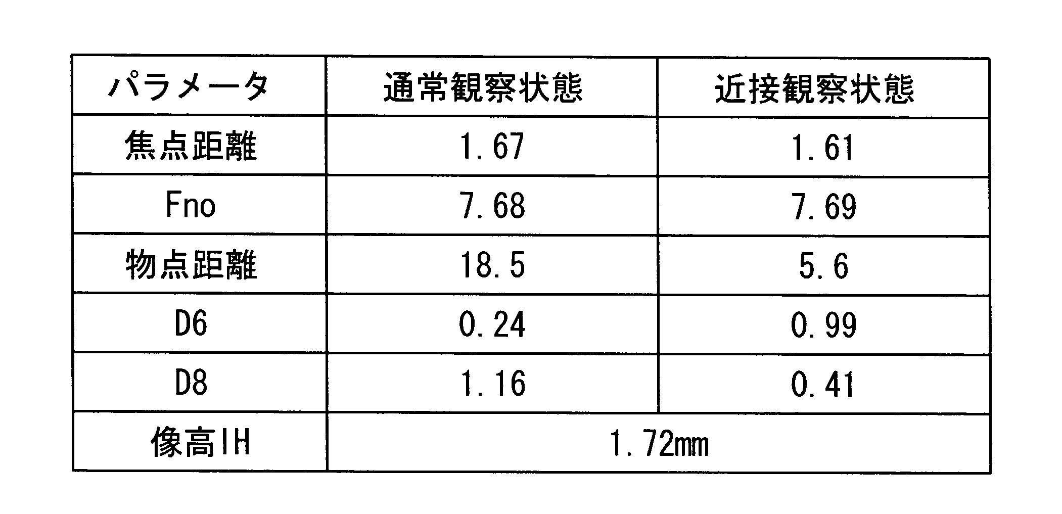
(実施例3)
実施例3に係る対物光学系の構成を図11および図12に、そのレンズデータを下に示す。図11は通常観察状態(遠距離物点)を、図12は近接観察状態(近距離物点)を示している。本実施例の対物光学系は、第1群が、物体側より順に、負レンズおよびパワーの弱い負レンズにより構成され、第2群が、正レンズにて構成され、第3群が物体側より順に、正レンズ、平行平面板、および、正レンズと負レンズとを貼り合せた正の接合レンズにより構成されている。第3群の後方には、平行平面板が配置されている。
このように構成された対物光学系の通常観察状態と近接観察状態の2状態における変動パラメータの値を表3に示し、各状態における収差図を図13および図14示す。
実施例3に係る対物光学系の構成を図11および図12に、そのレンズデータを下に示す。図11は通常観察状態(遠距離物点)を、図12は近接観察状態(近距離物点)を示している。本実施例の対物光学系は、第1群が、物体側より順に、負レンズおよびパワーの弱い負レンズにより構成され、第2群が、正レンズにて構成され、第3群が物体側より順に、正レンズ、平行平面板、および、正レンズと負レンズとを貼り合せた正の接合レンズにより構成されている。第3群の後方には、平行平面板が配置されている。
このように構成された対物光学系の通常観察状態と近接観察状態の2状態における変動パラメータの値を表3に示し、各状態における収差図を図13および図14示す。
レンズデータ
面番号 曲率半径 面間隔 屈折率Ne アッベ数νd
1 ∞ 0.38 1.88815 40.76
2 1.217 0.68
3 -10.344 0.67 1.88815 40.76
4 -18.708 D4
5 1.465 0.49 1.59143 61.14
6 1.748 D6
7 明るさ絞り 0.20
8 4.217 1.11 1.77621 49.60
9 -4.217 0.62
10 ∞ 0.31 1.51564 75.00
11 ∞ 0.62
12 4.197 1.58 1.48915 70.23
13 -1.902 0.40 1.93430 18.90
14 -4.776 1.22
15 ∞ 0.40 1.52498 59.89
16 ∞ 0.30
17 ∞ 0.40 1.51825 64.14
18 ∞ 1.00 1.50801 60.00
19 撮像面
面番号 曲率半径 面間隔 屈折率Ne アッベ数νd
1 ∞ 0.38 1.88815 40.76
2 1.217 0.68
3 -10.344 0.67 1.88815 40.76
4 -18.708 D4
5 1.465 0.49 1.59143 61.14
6 1.748 D6
7 明るさ絞り 0.20
8 4.217 1.11 1.77621 49.60
9 -4.217 0.62
10 ∞ 0.31 1.51564 75.00
11 ∞ 0.62
12 4.197 1.58 1.48915 70.23
13 -1.902 0.40 1.93430 18.90
14 -4.776 1.22
15 ∞ 0.40 1.52498 59.89
16 ∞ 0.30
17 ∞ 0.40 1.51825 64.14
18 ∞ 1.00 1.50801 60.00
19 撮像面

表4に、実施例1から3に係る対物光学系における条件式(1)から(11)の数値を示す。

(付記)
なお、これらの実施例から以下の構成の発明が導かれる。
(付記項1)
物体側から順に、第1群、第2群および第3群からなり、第1群が、物体側から順に、平凹レンズと、像側に凸面を向けたメニスカスレンズとからなり、第2群が、正のパワーを有し、光軸方向の移動によってフォーカシングを行う対物光学系。
なお、これらの実施例から以下の構成の発明が導かれる。
(付記項1)
物体側から順に、第1群、第2群および第3群からなり、第1群が、物体側から順に、平凹レンズと、像側に凸面を向けたメニスカスレンズとからなり、第2群が、正のパワーを有し、光軸方向の移動によってフォーカシングを行う対物光学系。
(付記項2)
第1群が、負のパワーを有し、第3群が、正のパワーを有する付記項1に記載の対物光学系。
(付記項3)
第2群が、物体側に凸面を向けた正メニスカスレンズからなり、第3群が、第1の正レンズ、および、第2の正レンズと負レンズとの接合レンズからなる付記項1に記載の対物光学系。
第1群が、負のパワーを有し、第3群が、正のパワーを有する付記項1に記載の対物光学系。
(付記項3)
第2群が、物体側に凸面を向けた正メニスカスレンズからなり、第3群が、第1の正レンズ、および、第2の正レンズと負レンズとの接合レンズからなる付記項1に記載の対物光学系。
(付記項4)
以下の条件式(1)および(2)を満足する付記項1に記載の対物光学系。
(1) |f/f2| < 0.12
(2) 0.92 < f/IH < 1.08
ただし、fは遠点観察時の全系の焦点距離、f2はメニスカスレンズの焦点距離、IHは像高である。
以下の条件式(1)および(2)を満足する付記項1に記載の対物光学系。
(1) |f/f2| < 0.12
(2) 0.92 < f/IH < 1.08
ただし、fは遠点観察時の全系の焦点距離、f2はメニスカスレンズの焦点距離、IHは像高である。
(付記項5)
物体側から順に平凹レンズ、像側に凸面を向けたメニスカスレンズ、絞り、両面が凸面である第1の正レンズ、および、第2の正レンズと負レンズとの接合レンズからなり、以下の条件式(3)を満足する対物光学系。
(3) 0.08 < d/f < 0.32
ただし、dはメニスカスレンズと第1の正レンズとの空気間隔である。
物体側から順に平凹レンズ、像側に凸面を向けたメニスカスレンズ、絞り、両面が凸面である第1の正レンズ、および、第2の正レンズと負レンズとの接合レンズからなり、以下の条件式(3)を満足する対物光学系。
(3) 0.08 < d/f < 0.32
ただし、dはメニスカスレンズと第1の正レンズとの空気間隔である。
(付記項6)
第1群のメニスカスレンズが、パワーの弱い正または負レンズである付記項1に記載の対物光学系。
(付記項7)
以下の条件式(4)を満足する付記項1から付記項5のいずれかに記載の対物光学系。
(4) -0.94 < f1/f < -0.72
ただし、f1は平凹レンズの焦点距離である。
第1群のメニスカスレンズが、パワーの弱い正または負レンズである付記項1に記載の対物光学系。
(付記項7)
以下の条件式(4)を満足する付記項1から付記項5のいずれかに記載の対物光学系。
(4) -0.94 < f1/f < -0.72
ただし、f1は平凹レンズの焦点距離である。
(付記項8)
以下の条件式(5)を満足する付記項1から付記項5のいずれかに記載の対物光学系。
(5) 5.1 < f3/f < 8.4
ただし、f3は第3レンズの焦点距離である。
(付記項9)
以下の条件式(6)を満足する付記項3または付記項5に記載の対物光学系。
(6) 1.2 < f4/f < 2.6
ただし、f4は第1の正レンズの焦点距離である。
以下の条件式(5)を満足する付記項1から付記項5のいずれかに記載の対物光学系。
(5) 5.1 < f3/f < 8.4
ただし、f3は第3レンズの焦点距離である。
(付記項9)
以下の条件式(6)を満足する付記項3または付記項5に記載の対物光学系。
(6) 1.2 < f4/f < 2.6
ただし、f4は第1の正レンズの焦点距離である。
(付記項10)
以下の条件式(7)を満足する付記項3から付記項5のいずれかに記載の対物光学系。
(7) 0.55 < |f5/f6| < 0.94
ただし、f5は第2の正レンズの焦点距離、f6は負レンズの焦点距離である。
(付記項11)
以下の条件式(8)を満足する付記項3または付記項5に記載の対物光学系。
(8) 0.95 < |r/f| < 1.3
ただし、rは第2の正レンズと負レンズとの接合面曲率半径である。
以下の条件式(7)を満足する付記項3から付記項5のいずれかに記載の対物光学系。
(7) 0.55 < |f5/f6| < 0.94
ただし、f5は第2の正レンズの焦点距離、f6は負レンズの焦点距離である。
(付記項11)
以下の条件式(8)を満足する付記項3または付記項5に記載の対物光学系。
(8) 0.95 < |r/f| < 1.3
ただし、rは第2の正レンズと負レンズとの接合面曲率半径である。
(付記項12)
以下の条件式(9)を満足する付記項1から付記項5のいずれかに記載の対物光学系。
(9) 6 < LTL/f < 8
ただし、LTLはレンズ系全長である。
(付記項13)
以下の条件式(10)を満足する付記項1から付記項5のいずれかに記載の対物光学系。
(10) 0.8 < ωn / ωf < 1.2
ただし、ωfは遠距離観察時の最大半画角、ωnは近接観察時の最大半画角である。
以下の条件式(9)を満足する付記項1から付記項5のいずれかに記載の対物光学系。
(9) 6 < LTL/f < 8
ただし、LTLはレンズ系全長である。
(付記項13)
以下の条件式(10)を満足する付記項1から付記項5のいずれかに記載の対物光学系。
(10) 0.8 < ωn / ωf < 1.2
ただし、ωfは遠距離観察時の最大半画角、ωnは近接観察時の最大半画角である。
(付記項14)
以下の条件式(11)を満足する付記項1から付記項5のいずれかに記載の対物光学系。
(11) ωf > 60
以下の条件式(11)を満足する付記項1から付記項5のいずれかに記載の対物光学系。
(11) ωf > 60
1 対物光学系
2 封止チップガラス
3 光学部材
F1,F2 平行平面板
G1 第1群
G2 第2群
G3 第3群
L1 第1レンズ(平凹レンズ)
L2 第2レンズ(メニスカスレンズ)
L3 第3レンズ(正メニスカスレンズ)
L4 第4レンズ(第1の正レンズ)
L5 正レンズ(第2の正レンズ)
L6 負レンズ(負レンズ)
L56 第5レンズ(接合レンズ)
S 明るさ絞り
2 封止チップガラス
3 光学部材
F1,F2 平行平面板
G1 第1群
G2 第2群
G3 第3群
L1 第1レンズ(平凹レンズ)
L2 第2レンズ(メニスカスレンズ)
L3 第3レンズ(正メニスカスレンズ)
L4 第4レンズ(第1の正レンズ)
L5 正レンズ(第2の正レンズ)
L6 負レンズ(負レンズ)
L56 第5レンズ(接合レンズ)
S 明るさ絞り
Claims (5)
- 物体側から順に、第1群、第2群および第3群からなり、
前記第1群が、物体側から順に、平凹レンズと、像側に凸面を向けたメニスカスレンズとからなり、
前記第2群が、正のパワーを有し、光軸方向の移動によってフォーカシングを行う対物光学系。 - 前記第1群が、負のパワーを有し、
前記第3群が、正のパワーを有する請求項1に記載の対物光学系。 - 前記第2群が、物体側に凸面を向けた正メニスカスレンズからなり、
前記第3群が、第1の正レンズ、および、第2の正レンズと負レンズとの接合レンズからなる請求項1に記載の対物光学系。 - 以下の条件式(1)および(2)を満足する請求項1に記載の対物光学系。
(1) |f/f2| < 0.12
(2) 0.92 < f/IH < 1.08
ただし、
f:遠点観察時の全系の焦点距離、
f2:メニスカスレンズの焦点距離、
IH:像高
である。 - 物体側から順に、平凹レンズ、像側に凸面を向けたメニスカスレンズ、絞り、両面が凸面である第1の正レンズ、および、第2の正レンズと負レンズとの接合レンズからなり、以下の条件式(3)を満足する対物光学系。
(3) 0.08 < d/f < 0.32
ただし、
d:メニスカスレンズと第1の正レンズの空気間隔
である。
Priority Applications (4)
| Application Number | Priority Date | Filing Date | Title |
|---|---|---|---|
| JP2011536669A JP4934233B2 (ja) | 2009-12-11 | 2010-11-29 | 対物光学系 |
| CN201080046866.6A CN102687053B (zh) | 2009-12-11 | 2010-11-29 | 物镜光学系统 |
| EP10835852.4A EP2477053B1 (en) | 2009-12-11 | 2010-11-29 | Endoscope objective optical system |
| US13/199,257 US8456767B2 (en) | 2009-12-11 | 2011-08-23 | Objective optical system |
Applications Claiming Priority (2)
| Application Number | Priority Date | Filing Date | Title |
|---|---|---|---|
| JP2009-282205 | 2009-12-11 | ||
| JP2009282205 | 2009-12-11 |
Related Child Applications (1)
| Application Number | Title | Priority Date | Filing Date |
|---|---|---|---|
| US13/199,257 Continuation US8456767B2 (en) | 2009-12-11 | 2011-08-23 | Objective optical system |
Publications (1)
| Publication Number | Publication Date |
|---|---|
| WO2011070930A1 true WO2011070930A1 (ja) | 2011-06-16 |
Family
ID=44145475
Family Applications (1)
| Application Number | Title | Priority Date | Filing Date |
|---|---|---|---|
| PCT/JP2010/071213 Ceased WO2011070930A1 (ja) | 2009-12-11 | 2010-11-29 | 対物光学系 |
Country Status (5)
| Country | Link |
|---|---|
| US (1) | US8456767B2 (ja) |
| EP (1) | EP2477053B1 (ja) |
| JP (1) | JP4934233B2 (ja) |
| CN (1) | CN102687053B (ja) |
| WO (1) | WO2011070930A1 (ja) |
Cited By (23)
| Publication number | Priority date | Publication date | Assignee | Title |
|---|---|---|---|---|
| WO2013128882A1 (ja) * | 2012-02-28 | 2013-09-06 | 株式会社ニコン | 光学系、光学機器及び光学系の製造方法 |
| JP2013178391A (ja) * | 2012-02-28 | 2013-09-09 | Nikon Corp | 光学系、光学機器及び光学系の製造方法 |
| JP2013186222A (ja) * | 2012-03-07 | 2013-09-19 | Nikon Corp | 光学系、光学機器及び光学系の製造方法 |
| WO2014088104A1 (ja) * | 2012-12-07 | 2014-06-12 | オリンパス株式会社 | 対物レンズ及びそれを備えた観察装置 |
| WO2014129089A1 (ja) * | 2013-02-22 | 2014-08-28 | オリンパスメディカルシステムズ株式会社 | 内視鏡用対物光学系及び撮像装置 |
| JP2014197131A (ja) * | 2013-03-29 | 2014-10-16 | キヤノン株式会社 | 撮像レンズ及びそれを有する撮像装置 |
| EP2648026A4 (en) * | 2011-06-23 | 2014-11-19 | Olympus Medical Systems Corp | OPTICAL LENS SYSTEM FOR AN ENDOSCOPE |
| WO2015194311A1 (ja) * | 2014-06-20 | 2015-12-23 | オリンパス株式会社 | 内視鏡用対物光学系 |
| WO2016047421A1 (ja) * | 2014-09-22 | 2016-03-31 | オリンパス株式会社 | 内視鏡対物光学系 |
| WO2016067838A1 (ja) * | 2014-10-30 | 2016-05-06 | オリンパス株式会社 | 内視鏡用対物光学系 |
| CN105899993A (zh) * | 2014-08-28 | 2016-08-24 | 奥林巴斯株式会社 | 内窥镜物镜光学系统 |
| WO2016204001A1 (ja) * | 2015-06-18 | 2016-12-22 | オリンパス株式会社 | 内視鏡用対物光学系 |
| WO2017179373A1 (ja) * | 2016-04-12 | 2017-10-19 | オリンパス株式会社 | 内視鏡用対物光学系 |
| WO2018061385A1 (ja) * | 2016-09-28 | 2018-04-05 | オリンパス株式会社 | 内視鏡対物光学系 |
| CN109557657A (zh) * | 2017-09-27 | 2019-04-02 | 富士胶片株式会社 | 内窥镜用对物光学系统及内窥镜 |
| WO2019167310A1 (ja) * | 2018-02-27 | 2019-09-06 | オリンパス株式会社 | 内視鏡用対物光学系 |
| JP2020106797A (ja) * | 2018-12-27 | 2020-07-09 | エーエーシー テクノロジーズ ピーティーイー リミテッド | 撮像光学レンズ |
| JP2020181092A (ja) * | 2019-04-25 | 2020-11-05 | 富士フイルム株式会社 | 内視鏡用対物光学系および内視鏡 |
| US10845586B2 (en) | 2016-07-04 | 2020-11-24 | Olympus Corporation | Endoscope optical system |
| US10842360B2 (en) | 2016-04-13 | 2020-11-24 | Olympus Corporation | Objective optical system |
| US11375884B2 (en) * | 2011-09-27 | 2022-07-05 | California Institute Of Technology | Multi-angle rear-viewing endoscope and method of operation thereof |
| JP2023140115A (ja) * | 2022-03-22 | 2023-10-04 | 京セラ株式会社 | 撮像光学系及び撮像装置 |
| WO2024166167A1 (ja) * | 2023-02-06 | 2024-08-15 | オリンパスメディカルシステムズ株式会社 | 対物光学系、内視鏡及び撮像装置 |
Families Citing this family (69)
| Publication number | Priority date | Publication date | Assignee | Title |
|---|---|---|---|---|
| US9872609B2 (en) | 2009-06-18 | 2018-01-23 | Endochoice Innovation Center Ltd. | Multi-camera endoscope |
| EP2442706B1 (en) | 2009-06-18 | 2014-11-12 | EndoChoice Innovation Center Ltd. | Multi-camera endoscope |
| US9901244B2 (en) | 2009-06-18 | 2018-02-27 | Endochoice, Inc. | Circuit board assembly of a multiple viewing elements endoscope |
| US9101268B2 (en) | 2009-06-18 | 2015-08-11 | Endochoice Innovation Center Ltd. | Multi-camera endoscope |
| US10165929B2 (en) | 2009-06-18 | 2019-01-01 | Endochoice, Inc. | Compact multi-viewing element endoscope system |
| US11864734B2 (en) | 2009-06-18 | 2024-01-09 | Endochoice, Inc. | Multi-camera endoscope |
| US10130246B2 (en) | 2009-06-18 | 2018-11-20 | Endochoice, Inc. | Systems and methods for regulating temperature and illumination intensity at the distal tip of an endoscope |
| US9642513B2 (en) | 2009-06-18 | 2017-05-09 | Endochoice Inc. | Compact multi-viewing element endoscope system |
| US10524645B2 (en) | 2009-06-18 | 2020-01-07 | Endochoice, Inc. | Method and system for eliminating image motion blur in a multiple viewing elements endoscope |
| US11278190B2 (en) | 2009-06-18 | 2022-03-22 | Endochoice, Inc. | Multi-viewing element endoscope |
| US9474440B2 (en) | 2009-06-18 | 2016-10-25 | Endochoice, Inc. | Endoscope tip position visual indicator and heat management system |
| US11547275B2 (en) | 2009-06-18 | 2023-01-10 | Endochoice, Inc. | Compact multi-viewing element endoscope system |
| US12137873B2 (en) | 2009-06-18 | 2024-11-12 | Endochoice, Inc. | Compact multi-viewing element endoscope system |
| US9492063B2 (en) | 2009-06-18 | 2016-11-15 | Endochoice Innovation Center Ltd. | Multi-viewing element endoscope |
| WO2012077116A1 (en) | 2010-12-09 | 2012-06-14 | Peermedical Ltd. | Flexible electronic circuit board for a multi-camera endoscope |
| US8926502B2 (en) | 2011-03-07 | 2015-01-06 | Endochoice, Inc. | Multi camera endoscope having a side service channel |
| US9101287B2 (en) | 2011-03-07 | 2015-08-11 | Endochoice Innovation Center Ltd. | Multi camera endoscope assembly having multiple working channels |
| US9713417B2 (en) | 2009-06-18 | 2017-07-25 | Endochoice, Inc. | Image capture assembly for use in a multi-viewing elements endoscope |
| US9402533B2 (en) | 2011-03-07 | 2016-08-02 | Endochoice Innovation Center Ltd. | Endoscope circuit board assembly |
| US9706903B2 (en) | 2009-06-18 | 2017-07-18 | Endochoice, Inc. | Multiple viewing elements endoscope system with modular imaging units |
| US12220105B2 (en) | 2010-06-16 | 2025-02-11 | Endochoice, Inc. | Circuit board assembly of a multiple viewing elements endoscope |
| US9560953B2 (en) | 2010-09-20 | 2017-02-07 | Endochoice, Inc. | Operational interface in a multi-viewing element endoscope |
| EP4233680B1 (en) | 2010-09-20 | 2025-06-18 | EndoChoice, Inc. | Endoscope distal section comprising a unitary fluid channeling component |
| US9706908B2 (en) | 2010-10-28 | 2017-07-18 | Endochoice, Inc. | Image capture and video processing systems and methods for multiple viewing element endoscopes |
| EP2635932B1 (en) * | 2010-10-28 | 2019-06-05 | EndoChoice Innovation Center Ltd. | Optical systems for multi-sensor endoscopes |
| US10663714B2 (en) | 2010-10-28 | 2020-05-26 | Endochoice, Inc. | Optical system for an endoscope |
| US12204087B2 (en) | 2010-10-28 | 2025-01-21 | Endochoice, Inc. | Optical systems for multi-sensor endoscopes |
| US11889986B2 (en) | 2010-12-09 | 2024-02-06 | Endochoice, Inc. | Flexible electronic circuit board for a multi-camera endoscope |
| EP3420886B8 (en) | 2010-12-09 | 2020-07-15 | EndoChoice, Inc. | Flexible electronic circuit board multi-camera endoscope |
| US10517464B2 (en) | 2011-02-07 | 2019-12-31 | Endochoice, Inc. | Multi-element cover for a multi-camera endoscope |
| CN103491854B (zh) | 2011-02-07 | 2016-08-24 | 恩多卓斯创新中心有限公司 | 用于多摄影机内窥镜的多元件罩 |
| CA2798729A1 (en) | 2011-12-13 | 2013-06-13 | Peermedical Ltd. | Rotatable connector for an endoscope |
| CA2798716A1 (en) | 2011-12-13 | 2013-06-13 | Endochoice Innovation Center Ltd. | Removable tip endoscope |
| US9560954B2 (en) | 2012-07-24 | 2017-02-07 | Endochoice, Inc. | Connector for use with endoscope |
| CN104937470B (zh) * | 2013-02-28 | 2017-03-08 | 奥林巴斯株式会社 | 物镜光学系统 |
| US9993142B2 (en) | 2013-03-28 | 2018-06-12 | Endochoice, Inc. | Fluid distribution device for a multiple viewing elements endoscope |
| US9986899B2 (en) | 2013-03-28 | 2018-06-05 | Endochoice, Inc. | Manifold for a multiple viewing elements endoscope |
| US10595714B2 (en) | 2013-03-28 | 2020-03-24 | Endochoice, Inc. | Multi-jet controller for an endoscope |
| US9636003B2 (en) | 2013-06-28 | 2017-05-02 | Endochoice, Inc. | Multi-jet distributor for an endoscope |
| US12207796B2 (en) | 2013-03-28 | 2025-01-28 | Endochoice Inc. | Multi-jet controller for an endoscope |
| US9667935B2 (en) | 2013-05-07 | 2017-05-30 | Endochoice, Inc. | White balance enclosure for use with a multi-viewing elements endoscope |
| US10499794B2 (en) | 2013-05-09 | 2019-12-10 | Endochoice, Inc. | Operational interface in a multi-viewing element endoscope |
| US9949623B2 (en) | 2013-05-17 | 2018-04-24 | Endochoice, Inc. | Endoscope control unit with braking system |
| US10064541B2 (en) | 2013-08-12 | 2018-09-04 | Endochoice, Inc. | Endoscope connector cover detection and warning system |
| US9943218B2 (en) | 2013-10-01 | 2018-04-17 | Endochoice, Inc. | Endoscope having a supply cable attached thereto |
| US9968242B2 (en) | 2013-12-18 | 2018-05-15 | Endochoice, Inc. | Suction control unit for an endoscope having two working channels |
| WO2015112747A2 (en) | 2014-01-22 | 2015-07-30 | Endochoice, Inc. | Image capture and video processing systems and methods for multiple viewing element endoscopes |
| JP6339852B2 (ja) * | 2014-05-01 | 2018-06-06 | キヤノン株式会社 | ズームレンズ及びそれを有する撮像装置 |
| US11234581B2 (en) | 2014-05-02 | 2022-02-01 | Endochoice, Inc. | Elevator for directing medical tool |
| WO2016014581A1 (en) | 2014-07-21 | 2016-01-28 | Endochoice, Inc. | Multi-focal, multi-camera endoscope systems |
| CN111990946A (zh) | 2014-08-29 | 2020-11-27 | 恩多巧爱思股份有限公司 | 改变内窥镜插入管的刚度的系统和方法 |
| KR101691351B1 (ko) * | 2014-10-28 | 2016-12-30 | 주식회사 코렌 | 촬영 렌즈 광학계 |
| EP3235241B1 (en) | 2014-12-18 | 2023-09-06 | EndoChoice, Inc. | System for processing video images generated by a multiple viewing elements endoscope |
| US10271713B2 (en) | 2015-01-05 | 2019-04-30 | Endochoice, Inc. | Tubed manifold of a multiple viewing elements endoscope |
| US10376181B2 (en) | 2015-02-17 | 2019-08-13 | Endochoice, Inc. | System for detecting the location of an endoscopic device during a medical procedure |
| US12529882B2 (en) | 2015-02-24 | 2026-01-20 | Endochoice, Inc. | Optical system for an endoscope |
| US10078207B2 (en) | 2015-03-18 | 2018-09-18 | Endochoice, Inc. | Systems and methods for image magnification using relative movement between an image sensor and a lens assembly |
| US10401611B2 (en) | 2015-04-27 | 2019-09-03 | Endochoice, Inc. | Endoscope with integrated measurement of distance to objects of interest |
| EP3297515B1 (en) | 2015-05-17 | 2020-07-01 | Endochoice, Inc. | Endoscopic image enhancement using contrast limited adaptive histogram equalization (clahe) implemented in a processor |
| CN107076967B (zh) * | 2015-09-07 | 2020-09-01 | Hoya株式会社 | 内窥镜用变倍光学系统及内窥镜 |
| US9897779B2 (en) * | 2015-09-30 | 2018-02-20 | Apple Inc. | Camera lens system with three lens components |
| TWI586999B (zh) | 2015-10-23 | 2017-06-11 | 大立光電股份有限公司 | 影像擷取透鏡組、取像裝置及電子裝置 |
| JP6985262B2 (ja) | 2015-10-28 | 2021-12-22 | エンドチョイス インコーポレイテッドEndochoice, Inc. | 患者の体内における内視鏡の位置を追跡するための装置及び方法 |
| CN113425225B (zh) | 2015-11-24 | 2024-09-17 | 安多卓思公司 | 用于内窥镜的一次性空气/水阀和抽吸阀 |
| JP2019507628A (ja) | 2016-02-24 | 2019-03-22 | エンドチョイス インコーポレイテッドEndochoice, Inc. | Cmosセンサを用いた複数ビュー要素内視鏡のための回路基板アセンブリ |
| US10292570B2 (en) | 2016-03-14 | 2019-05-21 | Endochoice, Inc. | System and method for guiding and tracking a region of interest using an endoscope |
| EP4321081A3 (en) | 2016-06-21 | 2024-04-24 | EndoChoice, Inc. | Endoscope system with multiple connection interfaces to interface with different video data signal sources |
| TWI622824B (zh) | 2017-01-19 | 2018-05-01 | 大立光電股份有限公司 | 光學影像系統組、取像裝置及電子裝置 |
| US20240337812A1 (en) * | 2023-04-10 | 2024-10-10 | Gopro, Inc. | Adjustable-focus optical assemblies for image capture devices |
Citations (10)
| Publication number | Priority date | Publication date | Assignee | Title |
|---|---|---|---|---|
| JPS5515005B2 (ja) | 1974-10-26 | 1980-04-21 | ||
| JPS6144283B2 (ja) | 1978-12-29 | 1986-10-02 | Olympus Optical Co | |
| JPH06317744A (ja) | 1993-04-30 | 1994-11-15 | Olympus Optical Co Ltd | 内視鏡対物光学系 |
| JPH0990213A (ja) * | 1995-09-20 | 1997-04-04 | Casio Comput Co Ltd | 撮影レンズ |
| JPH11316339A (ja) | 1998-03-03 | 1999-11-16 | Olympus Optical Co Ltd | 対物光学系 |
| JP2000267002A (ja) | 1999-03-15 | 2000-09-29 | Olympus Optical Co Ltd | 光学系 |
| JP2000330015A (ja) | 1999-03-12 | 2000-11-30 | Fuji Photo Optical Co Ltd | 観察深度可変型の内視鏡用対物レンズ |
| JP2002028126A (ja) | 2000-07-14 | 2002-01-29 | Olympus Optical Co Ltd | 内視鏡装置 |
| JP2009151191A (ja) | 2007-12-21 | 2009-07-09 | Olympus Medical Systems Corp | 内視鏡用対物レンズ |
| JP2009163256A (ja) * | 2009-03-03 | 2009-07-23 | Olympus Corp | 光学系 |
Family Cites Families (16)
| Publication number | Priority date | Publication date | Assignee | Title |
|---|---|---|---|---|
| US4059344A (en) | 1974-10-26 | 1977-11-22 | Olympus Optical Co., Ltd. | Retrofocus-type objective for endoscopes |
| JPS592343B2 (ja) | 1978-07-19 | 1984-01-18 | 川崎製鉄株式会社 | 複合めつき被覆層中の金属Al量測定方法 |
| JPS6144283A (ja) | 1984-08-06 | 1986-03-03 | 井関農機株式会社 | 穀粒乾燥機の熱風温度検出装置 |
| JP2556984B2 (ja) * | 1988-02-05 | 1996-11-27 | オリンパス光学工業株式会社 | 内視鏡 |
| JP2899980B2 (ja) * | 1990-02-02 | 1999-06-02 | オリンパス光学工業株式会社 | 内視鏡用対物光学系 |
| JP3336592B2 (ja) * | 1993-03-31 | 2002-10-21 | 富士写真フイルム株式会社 | 変倍ファインダ |
| JP3590807B2 (ja) | 1995-03-08 | 2004-11-17 | 株式会社ニコン | ズームレンズ |
| JP2000162541A (ja) | 1998-11-30 | 2000-06-16 | Sanyo Electric Co Ltd | 採光装置 |
| JP4507594B2 (ja) | 2003-12-26 | 2010-07-21 | 日亜化学工業株式会社 | 半導体発光素子 |
| JP4659645B2 (ja) * | 2006-03-01 | 2011-03-30 | オリンパスメディカルシステムズ株式会社 | 拡大内視鏡光学系 |
| JP4931462B2 (ja) * | 2006-04-18 | 2012-05-16 | 日本電産コパル株式会社 | 撮像レンズ |
| JP2008107391A (ja) | 2006-10-23 | 2008-05-08 | Olympus Medical Systems Corp | 内視鏡対物光学系 |
| JP2009016325A (ja) | 2007-07-06 | 2009-01-22 | Masaya Nagasawa | 電源周波数の倍増 |
| JP2009047722A (ja) | 2007-08-13 | 2009-03-05 | Konica Minolta Opto Inc | 変倍光学系、撮像装置およびデジタル機器 |
| CN201122198Y (zh) * | 2007-11-30 | 2008-09-24 | 今鼎光电股份有限公司 | 光学镜头 |
| JP4653823B2 (ja) * | 2008-06-06 | 2011-03-16 | オリンパスメディカルシステムズ株式会社 | 対物光学系 |
-
2010
- 2010-11-29 CN CN201080046866.6A patent/CN102687053B/zh active Active
- 2010-11-29 JP JP2011536669A patent/JP4934233B2/ja active Active
- 2010-11-29 WO PCT/JP2010/071213 patent/WO2011070930A1/ja not_active Ceased
- 2010-11-29 EP EP10835852.4A patent/EP2477053B1/en not_active Not-in-force
-
2011
- 2011-08-23 US US13/199,257 patent/US8456767B2/en active Active
Patent Citations (10)
| Publication number | Priority date | Publication date | Assignee | Title |
|---|---|---|---|---|
| JPS5515005B2 (ja) | 1974-10-26 | 1980-04-21 | ||
| JPS6144283B2 (ja) | 1978-12-29 | 1986-10-02 | Olympus Optical Co | |
| JPH06317744A (ja) | 1993-04-30 | 1994-11-15 | Olympus Optical Co Ltd | 内視鏡対物光学系 |
| JPH0990213A (ja) * | 1995-09-20 | 1997-04-04 | Casio Comput Co Ltd | 撮影レンズ |
| JPH11316339A (ja) | 1998-03-03 | 1999-11-16 | Olympus Optical Co Ltd | 対物光学系 |
| JP2000330015A (ja) | 1999-03-12 | 2000-11-30 | Fuji Photo Optical Co Ltd | 観察深度可変型の内視鏡用対物レンズ |
| JP2000267002A (ja) | 1999-03-15 | 2000-09-29 | Olympus Optical Co Ltd | 光学系 |
| JP2002028126A (ja) | 2000-07-14 | 2002-01-29 | Olympus Optical Co Ltd | 内視鏡装置 |
| JP2009151191A (ja) | 2007-12-21 | 2009-07-09 | Olympus Medical Systems Corp | 内視鏡用対物レンズ |
| JP2009163256A (ja) * | 2009-03-03 | 2009-07-23 | Olympus Corp | 光学系 |
Non-Patent Citations (1)
| Title |
|---|
| See also references of EP2477053A4 |
Cited By (46)
| Publication number | Priority date | Publication date | Assignee | Title |
|---|---|---|---|---|
| EP2648026A4 (en) * | 2011-06-23 | 2014-11-19 | Olympus Medical Systems Corp | OPTICAL LENS SYSTEM FOR AN ENDOSCOPE |
| US8976468B2 (en) | 2011-06-23 | 2015-03-10 | Olympus Medical Systems Corp. | Endoscope objective optical system |
| US11375884B2 (en) * | 2011-09-27 | 2022-07-05 | California Institute Of Technology | Multi-angle rear-viewing endoscope and method of operation thereof |
| JP2013178391A (ja) * | 2012-02-28 | 2013-09-09 | Nikon Corp | 光学系、光学機器及び光学系の製造方法 |
| WO2013128882A1 (ja) * | 2012-02-28 | 2013-09-06 | 株式会社ニコン | 光学系、光学機器及び光学系の製造方法 |
| US10268026B2 (en) | 2012-02-28 | 2019-04-23 | Nikon Corporation | Optical system, optical apparatus and method for manufacturing the optical system |
| CN104145200A (zh) * | 2012-02-28 | 2014-11-12 | 株式会社尼康 | 光学系统、光学装置和制造光学系统的方法 |
| JP2013186222A (ja) * | 2012-03-07 | 2013-09-19 | Nikon Corp | 光学系、光学機器及び光学系の製造方法 |
| WO2014088104A1 (ja) * | 2012-12-07 | 2014-06-12 | オリンパス株式会社 | 対物レンズ及びそれを備えた観察装置 |
| JPWO2014088104A1 (ja) * | 2012-12-07 | 2017-01-05 | オリンパス株式会社 | 対物レンズ及びそれを備えた観察装置 |
| JP5607278B1 (ja) * | 2013-02-22 | 2014-10-15 | オリンパスメディカルシステムズ株式会社 | 内視鏡用対物光学系及び撮像装置 |
| US9459443B2 (en) | 2013-02-22 | 2016-10-04 | Olympus Corporation | Endoscopic objective optical system and imaging apparatus |
| WO2014129089A1 (ja) * | 2013-02-22 | 2014-08-28 | オリンパスメディカルシステムズ株式会社 | 内視鏡用対物光学系及び撮像装置 |
| JP2014197131A (ja) * | 2013-03-29 | 2014-10-16 | キヤノン株式会社 | 撮像レンズ及びそれを有する撮像装置 |
| WO2015194311A1 (ja) * | 2014-06-20 | 2015-12-23 | オリンパス株式会社 | 内視鏡用対物光学系 |
| JP5930257B1 (ja) * | 2014-06-20 | 2016-06-08 | オリンパス株式会社 | 内視鏡用対物光学系 |
| US9568726B2 (en) | 2014-06-20 | 2017-02-14 | Olympus Corporation | Objective optical system for endoscope |
| CN105899993A (zh) * | 2014-08-28 | 2016-08-24 | 奥林巴斯株式会社 | 内窥镜物镜光学系统 |
| CN105899993B (zh) * | 2014-08-28 | 2018-09-25 | 奥林巴斯株式会社 | 内窥镜物镜光学系统 |
| WO2016047421A1 (ja) * | 2014-09-22 | 2016-03-31 | オリンパス株式会社 | 内視鏡対物光学系 |
| US9817226B2 (en) | 2014-09-22 | 2017-11-14 | Olympus Corporation | Endoscope objective optical system |
| JPWO2016047421A1 (ja) * | 2014-09-22 | 2017-04-27 | オリンパス株式会社 | 内視鏡対物光学系 |
| US9766437B2 (en) | 2014-10-30 | 2017-09-19 | Olympus Corporation | Objective optical system for endoscope |
| WO2016067838A1 (ja) * | 2014-10-30 | 2016-05-06 | オリンパス株式会社 | 内視鏡用対物光学系 |
| JP5989292B1 (ja) * | 2014-10-30 | 2016-09-07 | オリンパス株式会社 | 内視鏡用対物光学系 |
| WO2016204001A1 (ja) * | 2015-06-18 | 2016-12-22 | オリンパス株式会社 | 内視鏡用対物光学系 |
| JP6109461B1 (ja) * | 2015-06-18 | 2017-04-05 | オリンパス株式会社 | 内視鏡用対物光学系 |
| US10018827B2 (en) | 2015-06-18 | 2018-07-10 | Olympus Corporation | Objective optical system for endoscope |
| US10775604B2 (en) | 2016-04-12 | 2020-09-15 | Olympus Corporation | Objective optical system for endoscope |
| JP6230770B1 (ja) * | 2016-04-12 | 2017-11-15 | オリンパス株式会社 | 内視鏡用対物光学系 |
| WO2017179373A1 (ja) * | 2016-04-12 | 2017-10-19 | オリンパス株式会社 | 内視鏡用対物光学系 |
| US10842360B2 (en) | 2016-04-13 | 2020-11-24 | Olympus Corporation | Objective optical system |
| US10845586B2 (en) | 2016-07-04 | 2020-11-24 | Olympus Corporation | Endoscope optical system |
| WO2018061385A1 (ja) * | 2016-09-28 | 2018-04-05 | オリンパス株式会社 | 内視鏡対物光学系 |
| US10942348B2 (en) | 2016-09-28 | 2021-03-09 | Olympus Corporation | Endoscope objective optical system |
| CN109557657A (zh) * | 2017-09-27 | 2019-04-02 | 富士胶片株式会社 | 内窥镜用对物光学系统及内窥镜 |
| CN109557657B (zh) * | 2017-09-27 | 2021-12-31 | 富士胶片株式会社 | 内窥镜用对物光学系统及内窥镜 |
| JPWO2019167310A1 (ja) * | 2018-02-27 | 2020-12-03 | オリンパス株式会社 | 対物光学系、及び内視鏡 |
| WO2019167310A1 (ja) * | 2018-02-27 | 2019-09-06 | オリンパス株式会社 | 内視鏡用対物光学系 |
| US11460676B2 (en) | 2018-02-27 | 2022-10-04 | Olympus Corporation | Objective optical system and endoscope |
| JP2020106797A (ja) * | 2018-12-27 | 2020-07-09 | エーエーシー テクノロジーズ ピーティーイー リミテッド | 撮像光学レンズ |
| JP2020181092A (ja) * | 2019-04-25 | 2020-11-05 | 富士フイルム株式会社 | 内視鏡用対物光学系および内視鏡 |
| JP7113783B2 (ja) | 2019-04-25 | 2022-08-05 | 富士フイルム株式会社 | 内視鏡用対物光学系および内視鏡 |
| JP2023140115A (ja) * | 2022-03-22 | 2023-10-04 | 京セラ株式会社 | 撮像光学系及び撮像装置 |
| JP7693600B2 (ja) | 2022-03-22 | 2025-06-17 | 京セラ株式会社 | 撮像光学系及び撮像装置 |
| WO2024166167A1 (ja) * | 2023-02-06 | 2024-08-15 | オリンパスメディカルシステムズ株式会社 | 対物光学系、内視鏡及び撮像装置 |
Also Published As
| Publication number | Publication date |
|---|---|
| EP2477053A1 (en) | 2012-07-18 |
| CN102687053A (zh) | 2012-09-19 |
| US20120057251A1 (en) | 2012-03-08 |
| EP2477053A4 (en) | 2013-07-10 |
| CN102687053B (zh) | 2014-11-05 |
| JP4934233B2 (ja) | 2012-05-16 |
| US8456767B2 (en) | 2013-06-04 |
| JPWO2011070930A1 (ja) | 2013-04-22 |
| EP2477053B1 (en) | 2019-06-19 |
Similar Documents
| Publication | Publication Date | Title |
|---|---|---|
| JP4934233B2 (ja) | 対物光学系 | |
| JP5948530B2 (ja) | 対物光学系 | |
| JP4819969B2 (ja) | 対物光学系 | |
| JP6197147B1 (ja) | 対物光学系 | |
| JP6266189B1 (ja) | 対物光学系 | |
| JP6501984B2 (ja) | 対物光学系 | |
| CN106255912B (zh) | 物镜光学系统 | |
| JP6266195B1 (ja) | 内視鏡対物光学系 | |
| CN107111111B (zh) | 内窥镜用物镜光学系统 | |
| CN106461929A (zh) | 内窥镜系统 | |
| JP7024100B2 (ja) | 対物光学系及び内視鏡 | |
| CN109923458B (zh) | 物镜光学系统 | |
| WO2016047421A1 (ja) | 内視鏡対物光学系 | |
| CN111868599B (zh) | 内窥镜用物镜光学系统 | |
| JP2019086678A (ja) | 対物光学系 | |
| JPWO2020174561A1 (ja) | 内視鏡用対物光学系及び内視鏡 | |
| JP6857572B2 (ja) | 内視鏡用対物光学系 |
Legal Events
| Date | Code | Title | Description |
|---|---|---|---|
| WWE | Wipo information: entry into national phase |
Ref document number: 201080046866.6 Country of ref document: CN |
|
| WWE | Wipo information: entry into national phase |
Ref document number: 2011536669 Country of ref document: JP |
|
| 121 | Ep: the epo has been informed by wipo that ep was designated in this application |
Ref document number: 10835852 Country of ref document: EP Kind code of ref document: A1 |
|
| WWE | Wipo information: entry into national phase |
Ref document number: 2010835852 Country of ref document: EP |
|
| NENP | Non-entry into the national phase |
Ref country code: DE |