WO2011071084A1 - 建設機械 - Google Patents
建設機械 Download PDFInfo
- Publication number
- WO2011071084A1 WO2011071084A1 PCT/JP2010/072043 JP2010072043W WO2011071084A1 WO 2011071084 A1 WO2011071084 A1 WO 2011071084A1 JP 2010072043 W JP2010072043 W JP 2010072043W WO 2011071084 A1 WO2011071084 A1 WO 2011071084A1
- Authority
- WO
- WIPO (PCT)
- Prior art keywords
- frame
- voltage cable
- power
- high voltage
- construction machine
- Prior art date
- Legal status (The legal status is an assumption and is not a legal conclusion. Google has not performed a legal analysis and makes no representation as to the accuracy of the status listed.)
- Ceased
Links
Images






Classifications
-
- B—PERFORMING OPERATIONS; TRANSPORTING
- B66—HOISTING; LIFTING; HAULING
- B66C—CRANES; LOAD-ENGAGING ELEMENTS OR DEVICES FOR CRANES, CAPSTANS, WINCHES, OR TACKLES
- B66C13/00—Other constructional features or details
- B66C13/12—Arrangements of means for transmitting pneumatic, hydraulic, or electric power to movable parts of devices
-
- E—FIXED CONSTRUCTIONS
- E02—HYDRAULIC ENGINEERING; FOUNDATIONS; SOIL SHIFTING
- E02F—DREDGING; SOIL-SHIFTING
- E02F9/00—Component parts of dredgers or soil-shifting machines, not restricted to one of the kinds covered by groups E02F3/00 - E02F7/00
- E02F9/24—Safety devices, e.g. for preventing overload
-
- B—PERFORMING OPERATIONS; TRANSPORTING
- B66—HOISTING; LIFTING; HAULING
- B66C—CRANES; LOAD-ENGAGING ELEMENTS OR DEVICES FOR CRANES, CAPSTANS, WINCHES, OR TACKLES
- B66C1/00—Load-engaging elements or devices attached to lifting or lowering gear of cranes or adapted for connection therewith for transmitting lifting forces to articles or groups of articles
- B66C1/04—Load-engaging elements or devices attached to lifting or lowering gear of cranes or adapted for connection therewith for transmitting lifting forces to articles or groups of articles by magnetic means
- B66C1/06—Load-engaging elements or devices attached to lifting or lowering gear of cranes or adapted for connection therewith for transmitting lifting forces to articles or groups of articles by magnetic means electromagnetic
- B66C1/08—Circuits therefor
-
- B—PERFORMING OPERATIONS; TRANSPORTING
- B66—HOISTING; LIFTING; HAULING
- B66C—CRANES; LOAD-ENGAGING ELEMENTS OR DEVICES FOR CRANES, CAPSTANS, WINCHES, OR TACKLES
- B66C23/00—Cranes comprising essentially a beam, boom, or triangular structure acting as a cantilever and mounted for translatory of swinging movements in vertical or horizontal planes or a combination of such movements, e.g. jib-cranes, derricks, tower cranes
- B66C23/62—Constructional features or details
-
- E—FIXED CONSTRUCTIONS
- E02—HYDRAULIC ENGINEERING; FOUNDATIONS; SOIL SHIFTING
- E02F—DREDGING; SOIL-SHIFTING
- E02F9/00—Component parts of dredgers or soil-shifting machines, not restricted to one of the kinds covered by groups E02F3/00 - E02F7/00
-
- E—FIXED CONSTRUCTIONS
- E02—HYDRAULIC ENGINEERING; FOUNDATIONS; SOIL SHIFTING
- E02F—DREDGING; SOIL-SHIFTING
- E02F9/00—Component parts of dredgers or soil-shifting machines, not restricted to one of the kinds covered by groups E02F3/00 - E02F7/00
- E02F9/08—Superstructures; Supports for superstructures
- E02F9/0833—Improving access, e.g. for maintenance, steps for improving driver's access, handrails
-
- E—FIXED CONSTRUCTIONS
- E02—HYDRAULIC ENGINEERING; FOUNDATIONS; SOIL SHIFTING
- E02F—DREDGING; SOIL-SHIFTING
- E02F9/00—Component parts of dredgers or soil-shifting machines, not restricted to one of the kinds covered by groups E02F3/00 - E02F7/00
- E02F9/08—Superstructures; Supports for superstructures
- E02F9/0858—Arrangement of component parts installed on superstructures not otherwise provided for, e.g. electric components, fenders, air-conditioning units
-
- E—FIXED CONSTRUCTIONS
- E02—HYDRAULIC ENGINEERING; FOUNDATIONS; SOIL SHIFTING
- E02F—DREDGING; SOIL-SHIFTING
- E02F9/00—Component parts of dredgers or soil-shifting machines, not restricted to one of the kinds covered by groups E02F3/00 - E02F7/00
- E02F9/20—Drives; Control devices
- E02F9/2025—Particular purposes of control systems not otherwise provided for
-
- E—FIXED CONSTRUCTIONS
- E02—HYDRAULIC ENGINEERING; FOUNDATIONS; SOIL SHIFTING
- E02F—DREDGING; SOIL-SHIFTING
- E02F9/00—Component parts of dredgers or soil-shifting machines, not restricted to one of the kinds covered by groups E02F3/00 - E02F7/00
- E02F9/20—Drives; Control devices
- E02F9/2058—Electric or electro-mechanical or mechanical control devices of vehicle sub-units
- E02F9/2062—Control of propulsion units
- E02F9/2075—Control of propulsion units of the hybrid type
-
- E—FIXED CONSTRUCTIONS
- E02—HYDRAULIC ENGINEERING; FOUNDATIONS; SOIL SHIFTING
- E02F—DREDGING; SOIL-SHIFTING
- E02F9/00—Component parts of dredgers or soil-shifting machines, not restricted to one of the kinds covered by groups E02F3/00 - E02F7/00
- E02F9/20—Drives; Control devices
- E02F9/2058—Electric or electro-mechanical or mechanical control devices of vehicle sub-units
- E02F9/2091—Control of energy storage means for electrical energy, e.g. battery or capacitors
Definitions
- the present invention relates to a construction machine.
- a so-called hybrid construction machine in which power is generated by a generator by driving an engine, the generated power is stored in a power storage device, and the driving of the engine is assisted by the stored power.
- a generator, a power storage device, and an inverter that controls charging / power feeding between them are arranged in close proximity, and wiring for connecting electrical devices is arranged. The length is shortened.
- an object of the present invention is to provide a construction machine having improved wiring safety.
- the construction machine of the present invention includes an engine, a power generation unit that generates power by driving the engine, a power storage unit that stores electric power generated by the power generation unit, and an electric drive unit that is driven by the power from the power storage unit.
- the high voltage cable for connecting the power generation means or the electric drive means and the power storage means to supply power is wired along the side surface of the frame structure member protruding in the vertical direction. It is said.
- the frame structure member since the high voltage cable is wired along the side surface of the frame structure member protruding in the vertical direction, the frame structure member becomes a standing wall and the high voltage cable is suitably protected, For example, even when a construction machine collides with an obstacle or the like, the high-voltage cable is suitably protected by the frame structure member, and as a result, safety can be improved.
- the high voltage cable wired along the side surface of the frame structure member specifically, the high voltage cable between the inverter connected to the power storage means and controlling the power generation means and the power generation means, or the power storage
- the high voltage cable between the inverter connected to the means and controlling the electric drive means and the electric drive means may be mentioned.
- the frame structural member is an A frame that supports the working boom so as to be movable up and down, and the high voltage cable is preferably wired along the inner side surface of the A frame.
- the high voltage cable is suitably protected by the highly rigid A frame, and safety can be improved.
- the A frame is arranged on the center side and away from the collision site, so that the high voltage cable is more suitably protected.
- the frame structural member is a side frame that constitutes an end of the base frame and forms a closed cross-sectional space, and the high-voltage cable is preferably routed through the side frame.
- a high-voltage cable is passed through a highly rigid side frame with a closed cross-section, so that the high-voltage cable is suitably protected and safety can be improved. Since the side frame surrounding the high voltage cable from the surroundings blocks the electromagnetic wave, the electromagnetic shielding property can be improved.
- the high voltage cable can be suitably protected and the safety can be improved.
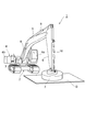
- FIG. 1 It is a perspective view showing the appearance of the construction machine concerning a 1st embodiment of the present invention.
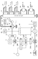
- It is a block diagram which shows internal structures, such as an electric system of the construction machine shown in FIG. 1, and a hydraulic system.
- It is a circuit diagram which shows the internal structure of the electrical storage means in FIG.
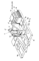
- FIG. 1 It is a perspective view which shows the house part of the turning body in FIG.
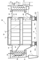
- FIG. 2 It is sectional drawing which shows the state which installed the capacitor box of the electrical storage means in the house part.
- FIG. 1 It is a perspective view which looks at FIG.
- FIG. 8 is a plan view of FIGS. 6 and 7. It is the perspective view which shows the high voltage cable wiring which connects a motor generator and its inverter circuit with the components in a base frame, A frame, and a house part right front part, and is the perspective view seen from vehicle left back upper direction.
- FIG. 10 is a perspective view of FIG. 9 viewed from the upper right rear side of the vehicle. It is a top view of FIG.9 and FIG.10. It is a XII-XII arrow line view of FIG.
- FIG.13 and FIG.14 It is a block diagram showing internal composition, such as an electric system of a construction machine concerning another embodiment, and a hydraulic system.
- FIG. 1 is a perspective view showing an appearance of a construction machine according to the first embodiment of the present invention.
- the construction machine of this embodiment is a so-called hybrid type construction machine, and shows a lifting magnet vehicle as an example.
- the lifting magnet vehicle 1 includes a traveling mechanism 2 including an endless track, and a revolving body 4 that is rotatably mounted on the upper portion of the traveling mechanism 2 via a revolving mechanism 3.
- the revolving body 4 is provided with a working boom 5, an arm 6 linked to the tip of the boom 5, and a lifting magnet 7 linked to the tip of the arm 6.
- the lifting magnet 7 is a facility for attracting and capturing a suspended load G such as a steel material by a magnetic force.
- the boom 5, arm 6 and lifting magnet 7 are hydraulically driven by a boom cylinder 8, an arm cylinder 9 and a bucket cylinder 10, respectively.
- the revolving body 4 includes a driver's cab 4a for accommodating an operator who operates the position of the lifting magnet 7, the excitation operation and the release operation, and an engine 11 which is a power source for generating hydraulic pressure (see FIG. 2). ) And the like.
- the engine 11 is composed of, for example, a diesel engine.
- FIG. 2 is a block diagram showing the internal configuration of the electrical system and hydraulic system of the construction machine shown in FIG. 1, and the configuration is called a so-called parallel system.
- the mechanical power transmission system is indicated by a double line
- the hydraulic system is indicated by a thick solid line
- the steering system is indicated by a broken line
- the electrical system is indicated by a thin solid line.
- FIG. 3 is a diagram showing the internal configuration of the power storage means 120 in FIG.
- the lifting magnet vehicle 1 includes a motor generator (power generation means) 12 and a transmission 13, and the rotation shafts of the engine 11 and the motor generator 12 are both connected to the input shaft of the transmission 13. Are connected to each other.
- the motor generator 12 assists the driving force of the engine 11 by driving the engine 11 as a work element, and the driving force of the motor generator 12 is used as the output shaft of the transmission 13. And then transmitted to the main pump 14.
- the driving force of the engine 11 is transmitted to the motor generator 12 via the transmission 13 so that the motor generator 12 generates power.
- the motor generator 12 is constituted by, for example, an IPM (Interior / Permanent / Magnetic) motor in which a magnet is embedded in a rotor. Switching between driving and power generation of the motor generator 12 is performed according to the load of the engine 11 and the like by the controller 30 that controls driving of the electric system in the lifting magnet vehicle 1.
- IPM Interior / Permanent / Magnetic
- a main pump 14 and a pilot pump 15 are connected to the output shaft of the transmission 13, and a control valve 17 is connected to the main pump 14 via a high-pressure hydraulic line 16.
- the control valve 17 is a device that controls the hydraulic system in the lifting magnet vehicle 1.
- a boom cylinder 8, an arm cylinder 9 and a bucket cylinder 10 are connected to the control valve 17 via a high pressure hydraulic line.
- the control valve 17 controls the hydraulic pressure supplied to them according to the operation input of the driver.
- the output terminal of an inverter circuit (inverter) 18A is connected to the electrical terminal of the motor generator 12.
- the power storage means 120 is connected to the input terminal of the inverter circuit 18A.
- the power storage means 120 includes a DC bus 110 that is a DC bus, a step-up / down converter 100, and a capacitor 19. That is, the input terminal of the inverter circuit 18 ⁇ / b> A is connected to the input terminal of the buck-boost converter 100 via the DC bus 110.
- a capacitor 19 is connected to the output terminal of the buck-boost converter 100.
- the capacitor 19 has a large number of cells.
- a battery may be used instead of the capacitor.
- the inverter circuit 18A controls the operation of the motor generator 12 based on a command from the controller 30. That is, when the inverter circuit 18A operates the motor generator 12 in electric (assist) operation, the necessary power is supplied from the capacitor 19 and the step-up / down converter 100 to the motor generator 12 via the DC bus 110. Further, when the motor generator 12 is caused to perform a power generation operation, the electric power generated by the motor generator 12 is charged into the capacitor 19 via the DC bus 110 and the step-up / down converter 100. The switching control between the step-up / step-down operation of the step-up / down converter 100 is performed by the controller 30 based on the DC bus voltage value, the capacitor voltage value, and the capacitor current value. As a result, the DC bus 110 can be maintained in a state of being stored at a predetermined constant voltage value.
- the lifting magnet 7 shown in FIG. 1 is connected to the DC bus 110 of the power storage means 120 via the inverter circuit 20B.
- the lifting magnet 7 includes an electromagnet that generates a magnetic force for magnetically attracting a metal object, and power is supplied from the DC bus 110 via the inverter circuit 20B.
- the inverter circuit 20 ⁇ / b> B supplies the requested power to the lifting magnet 7 from the DC bus 110 when the electromagnet is turned on based on a command from the controller 30. Further, when the electromagnet is turned off, the regenerated electric power is supplied to the DC bus 110.
- an inverter circuit (inverter) 20A is connected to the power storage means 120.
- One end of the inverter circuit 20A is connected to a turning electric motor (AC motor; electric drive means) 21 as a working electric motor, and the other end of the inverter circuit 20A is connected to the DC bus 110 of the power storage means 120.
- the turning electric motor 21 is a power source of the turning mechanism 3 shown in FIG.
- a resolver 22, a mechanical brake 23, and a turning speed reducer 24 are connected to the rotating shaft 21 ⁇ / b> A of the turning electric motor 21.
- the turning electric motor 21 When the turning electric motor 21 performs a power running operation, the rotational force of the rotational driving force of the turning electric motor 21 is amplified by the turning speed reducer 24, and the turning body 4 is subjected to acceleration / deceleration control to perform rotational movement. Further, due to the inertial rotation of the swing body 4, the rotation speed is increased by the swing speed reducer 24 and transmitted to the swing electric motor 21 to generate regenerative power.
- the electric motor 21 for turning is AC driven by the inverter circuit 20A by a PWM (Pulse Width Modulation) control signal.
- PWM Pulse Width Modulation
- the resolver 22 is a sensor that detects the rotation position and rotation angle of the rotation shaft 21A of the turning electric motor 21, and mechanically connected to the turning electric motor 21 to detect the rotation angle and rotation direction of the rotation shaft 21A.
- the mechanical brake 23 is a braking device that generates a mechanical braking force, and mechanically stops the rotating shaft 21 ⁇ / b> A of the turning electric motor 21 according to a command from the controller 30.
- the turning speed reducer 24 is a speed reducer that reduces the rotational speed of the rotating shaft 21 ⁇ / b> A of the turning electric motor 21 and mechanically transmits it to the turning mechanism 3.
- the motor generator 12, the turning motor 21, and the lifting magnet 7 are connected to the DC bus 110 via the inverter circuits 18A, 20A, and 20B, the power generated by the motor generator 12 is lifted.
- the magnet 7 or the turning electric motor 21 may be directly supplied, and in some cases, the electric power regenerated by the lifting magnet 7 may be supplied to the motor generator 12 or the turning electric motor 21. In some cases, the electric power regenerated in step 1 is supplied to the motor generator 12 or the lifting magnet 7.
- An operating device 26 is connected to the pilot pump 15 via a pilot line 25.
- the operating device 26 is an operating device for operating the turning electric motor 21, the traveling mechanism 2, the boom 5, the arm 6, and the lifting magnet 7, and is operated by an operator.
- a control valve 17 is connected to the operating device 26 via a hydraulic line 27, and a pressure sensor 29 is connected via a hydraulic line 28.
- the operating device 26 converts the hydraulic pressure (primary hydraulic pressure) supplied through the pilot line 25 into a hydraulic pressure (secondary hydraulic pressure) corresponding to the operation amount of the operator and outputs the hydraulic pressure.
- the secondary hydraulic pressure output from the operating device 26 is supplied to the control valve 17 through the hydraulic line 27 and detected by the pressure sensor 29.
- the pressure sensor 29 detects this operation amount as a change in the hydraulic pressure in the hydraulic line 28.
- the pressure sensor 29 outputs an electrical signal indicating the hydraulic pressure in the hydraulic line 28. This electric signal is input to the controller 30 and used for driving control of the turning electric motor 21.
- the controller 30 constitutes a control circuit in the present embodiment.
- the controller 30 is configured by an arithmetic processing unit including a CPU and an internal memory, and is realized by the CPU executing a drive control program stored in the internal memory.
- the power source of the controller 30 is a battery (for example, a 24V on-vehicle battery) different from the capacitor 19.
- the controller 30 converts a signal representing an operation amount for turning the turning mechanism 3 among signals inputted from the pressure sensor 29 into a speed command, and performs drive control of the turning electric motor 21.
- controller 30 is a capacitor by controlling the operation of the motor generator 12 (switching between assist operation and power generation operation), driving control of the lifting magnet 7 (switching between excitation and demagnetization), and driving control of the buck-boost converter 100. 19 charge / discharge control is performed.
- the step-up / step-down converter 100 has a step-up / step-down switching control system, and includes a reactor 101 and transistors 100B and 100C.
- the transistor 100B is a step-up switching element
- the transistor 100C is a step-down switching element.
- the transistors 100B and 100C are composed of, for example, an IGBT (Insulated Gate Bipolar Transistor) and are connected in series with each other.
- IGBT Insulated Gate Bipolar Transistor
- the collector of the transistor 100B and the emitter of the transistor 100C are connected to each other, the emitter of the transistor 100B is connected to the negative terminal of the capacitor 19 and the negative wiring of the DC bus 110, and the collector of the transistor 100C is connected to the DC It is connected to the positive side wiring of the bus 110.
- Reactor 101 has one end connected to the collector of transistor 100B and the emitter of transistor 100C, and the other end connected to the positive terminal of capacitor 19.
- a PWM voltage is applied from the controller 30 to the gates of the transistors 100B and 100C.
- a diode 100b which is a rectifier, is connected in parallel in the reverse direction between the collector and emitter of the transistor 100B.
- a diode 100c is connected in parallel in the reverse direction between the collector and emitter of the transistor 100C.
- a smoothing capacitor 110a is connected in the DC bus 110 between the collector of the transistor 100C and the emitter of the transistor 100B (that is, between the positive side wiring and the negative side wiring of the DC bus 110). The capacitor 110 a smoothes the output voltage from the step-up / down converter 100, the generated voltage from the motor generator 12, and the regenerative voltage from the turning electric motor 21.
- the buck-boost converter 100 having such a configuration, when DC power is supplied from the capacitor 19 to the DC bus 110, a PWM voltage is applied to the gate of the transistor 100B according to a command from the controller 30. Then, the induced electromotive force generated in the reactor 101 when the transistor 100B is turned on / off is transmitted through the diode 100c, and this power is smoothed by the capacitor 110a.
- a PWM voltage is applied to the gate of the transistor 100 ⁇ / b> C according to a command from the controller 30, and the current output from the transistor 100 ⁇ / b> C is smoothed by the reactor 101. Is done.
- FIG. 4 is a perspective view showing the house part 4 b of the revolving structure 4.
- the house part 4b is comprised so that it may become substantially U shape in planar view, and it arrange
- the right front portion (the left front portion shown in FIG. 4) of the vehicle is the right front portion Rf, the right rear portion (the left back portion shown in FIG.
- the right rear portion Rr is the right rear portion Rr, and the left front portion (shown in FIG. 4).
- the right front portion is referred to as the left front portion Lf
- the left rear portion is referred to as the left rear portion Lr
- the portion between the right front portion Rf and the left front portion Lf is referred to as the center portion C.
- the revolving structure 4 having the house portion 4b is rotated around the axis in the vertical direction by a revolving electric motor 21 (see FIG. 2) provided at the lower portion of the central portion C, that is, left and right along the revolving direction D.
- the right front portion Rf is provided with a step 31 and a handrail 32 for maintenance work.
- the power storage means 120, inverter circuits 18A, 20A, 20B, and the controller 30 shown in FIG. 2 are installed. Openings are formed in the lower left and right surfaces of the right front portion Rf, and the capacitor 19 of the power storage means 120 is installed between the opening 34 (see FIG. 5) on the right surface and the opening 33 on the left surface. Yes. That is, the openings 34 and 33 on the left and right surfaces are formed as vents that allow air for cooling the capacitor 19 to pass in the left and right direction.
- FIG. 5 is a cross-sectional view of the capacitor 19 and the like installed at the lower part of the right front portion Rf as viewed from the front.
- FIG. 5 shows a base frame B composed of a bottom frame Ba, which is a skeleton member that forms the bottom of the house portion 4b, and an outer peripheral frame Bb erected on the periphery (left side in FIG. 5) of the bottom frame Ba. It is shown.
- louvers 36 and 35 are respectively provided inside the right-side opening 34 and the left-side opening 33 in the right front portion Rf.
- a capacitor box 80 including the capacitor 19 is installed on the bottom frame Ba between the louvers 35 and 36 via a pedestal 155 and a vibration isolating rubber 156.
- the capacitor 19 is formed by arranging a large number of cells 41 in an upper stage and a lower stage, and an upper module 45 is constituted by an assembly of the upper cells 41, and a lower module 45 is constituted by an assembly of the lower cells 41.
- the capacitor box 80 is obtained by enclosing and reinforcing these modules 45, 45 with an outer frame so as to allow ventilation in the left-right direction.
- the intake duct 40 is connected to the right side (left side in FIG. 5) of the capacitor box 80, and a louver 38 is provided at the upstream end of the intake duct 40 so as to face the louver 36. Also, fans 43, 43 for flowing cooling air from the left to the right in the figure are provided at the left end (right side in FIG. 5) of the capacitor box 80 in correspondence with the upper and lower cells 41, 41, respectively. Further, an exhaust duct 39 is connected to the left side (right side in FIG. 5), and a louver 37 is provided at the downstream end of the exhaust duct 39 so as to face the louver 35.
- louver 36 on the intake side is inclined downward with respect to the flow direction of the cooling air flowing from the left to the right in the drawing, and the louver 38 in the intake duct 40 downstream thereof is inclined upward in the opposite direction to the louver 36.
- the louver 37 in the exhaust duct 39 is inclined downward with respect to the flow direction of the cooling air, and the exhaust-side louver 35 downstream thereof is inclined upward in the opposite direction to the louver 37.
- the intake duct 40 and the exhaust duct 39 have a vertically asymmetric shape. That is, the intake duct 40 and the exhaust duct 39 have a shape that expands downward from the louvers 38 and 37 on both sides toward the capacitor box 80.
- a partition wall 44 that connects the upstream end between the upper module 45 and the lower module 45 and the downstream end of the louver 38 and partitions the interior of the intake duct 40 up and down. Is provided.
- the partition wall 44 also distributes the same amount of cooling air as the upper module 45 to the lower module 45 which is disposed below the louver 38 arranged side by side without being directly opposed. In order to increase the flow rate at the lower inlet than the flow rate at the upper inlet (louver 38 outlet), it is not horizontal but inclined downward with respect to the flow direction of the cooling air. Has been.
- the capacitor box 80, the intake duct 40, the exhaust duct 39, the opening 34, the opening 33, and the like are installed in the right front portion Rf, but are installed below the cab 4a in the left front portion Lf. It may be.
- an engine radiator an oil cooler, an intercooler, a fuel cooler, a hybrid system radiator (hybrid radiator), a heat exchanger for an air conditioner of the cab 4a (an air conditioner condenser). ) (Both not shown) are installed.
- the engine 11, the transmission 13, the motor generator 12, the main pump 14, and the like shown in FIG. 2 are installed from the left rear portion Lr to the right rear portion Rr, that is, below the engine hood H constituting the top plate. ing.
- a fan (not shown) is connected to the engine 11, and the fan rotates with the rotation of the engine 11, so that the air vent 46 provided on the left side surface of the left front portion Lf is directed into the left rear portion Lr. Air flows, and each of the coolers installed in the left rear portion Lr is cooled.
- a frame 47 which is a frame body that supports the boom 5 so as to be able to move up and down
- boom cylinder frame 48 which is a frame body to which the base end of the boom cylinder 8 is attached.
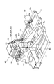
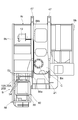
- FIG. 6 is a perspective view showing the wiring of the high voltage cable 63 that connects the turning electric motor 21 and the inverter circuit 20A together with the components in the base frame B, the A frame 47, and the right front portion Rf of the house.
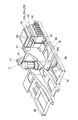
- FIG. 7 is a perspective view of FIG. 6 viewed from the upper right rear side of the vehicle
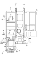
- FIG. 8 is a plan view of FIGS. 6 and 7
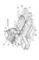
- FIG. 9 is a motor generator 12 and its inverter circuit.
- FIG. 10 is a perspective view showing the wiring of the high voltage cable 53 connecting to 18A together with the components in the base frame B, the A frame 47, and the right front portion of the house portion Rf, as seen from the upper left rear of the vehicle
- FIG. 9 is a perspective view of FIG. 9 as viewed from the upper right rear side of the vehicle
- FIG. 11 is a plan view of FIGS. 9 and 10
- FIG. 12 is a view taken in the direction of arrows XII-XII in FIG.
- a capacitor box 80 to which an intake duct 40 and an exhaust duct 39 are connected from bottom to top, an inverter circuit 18A, 20A, 20B and the controller 30 are mounted.
- a pump chamber (not shown) is formed in the house portion 4b on the base frame B, and a transmission 13, a motor generator 12, and a main pump 14 are provided in the pump chamber. .
- a frames (frame structure members) 47 and 47 that support the boom 5 are provided so as to protrude in the vertical direction, and are sandwiched between these A frames 47 and 47.
- the electric motor 21 for rotation is provided in a substantially upright state with respect to the bottom frame Ba near the rear of the boom 5 at the position.
- outer peripheral frames (side frames; frame structural members) Bb constituting the base frame B are provided at both left and right ends of the base frame B so as to extend in the front-rear direction.
- the outer peripheral frame Bb has a rectangular tube shape extending in the vertical direction, and forms a substantially rectangular closed cross-sectional space S therein.
- the high voltage cable 63 for connecting the turning electric motor 21 and the inverter circuit 20A to supply electric power is wired along the inner side surface of the A frame 47. ing.
- an opening 88a for passing the three-phase (U, V, W) high-voltage cable 63 is formed at a position near the capacitor box 80 below the A frame 47 on the capacitor box 80 side.
- the high voltage cable 63 from the turning electric motor 21 is wound along the inner surface of the lower portion of the A frame 47 protruding in the vertical direction on the capacitor box 80 side, and is led out of the A frame 47 through the opening 88a. And connected to the three-phase terminals 64 of the inverter circuit 20A.
- the high voltage cable 53 for connecting the motor generator 12 and its inverter circuit 18A to supply electric power is routed through the outer peripheral frame Bb.
- the frame structural members Bb and 47 since the high voltage cables 53 and 63 are wired along the side surfaces of the frame structural members Bb and 47 projecting in the vertical direction, the frame structural members Bb and 47 become standing walls. Thus, the high voltage cables 53 and 63 are suitably protected. For example, even when the lifting magnet vehicle 1 collides with an obstacle or the like, the high voltage cables 53 and 63 are suitably protected by the frame structural members Bb and 47. As a result, safety has been improved.
- the high voltage cable 63 constituting the frame structural member is wired along the inner side surface of the A frame 47, the high voltage cable 63 is suitably protected by the highly rigid A frame 47. Safety has been improved. In addition, even when the lifting magnet vehicle 1 collides with an obstacle or the like, the A frame 47 is disposed on the center side and away from the collision site, so that the high voltage cable 63 is more suitably protected.
- the high voltage cable 53 constituting the frame structural member has a closed cross section and is passed through the outer peripheral frame Bb having high rigidity, so that the high voltage cable 53 is suitably protected and safety is improved.
- the outer peripheral frame Bb that surrounds the high voltage cable 53 from the periphery is made of metal and the outer peripheral frame Bb blocks electromagnetic waves, so that the electromagnetic shielding property is also improved.
- the high voltage cables 53 and 63 can be wired separately from the low voltage (for example, 24V) control harness connected to the controller 30 or the like, noise due to the high voltage cables 53 and 63 for the harness is reduced. it can.
- the high voltage cable 63 is provided with a waterproof cap (not shown) at a portion passing through the frame of the turning electric motor 21, and the high voltage cable 53 is provided with a waterproof cap at a portion passing through the frame of the motor generator 12. (Not shown) is provided, and the inside of the frame is sufficiently waterproofed.
- waterproof caps for example, waterproof caps made of fluororesin and having heat resistance can be used.
- FIG. 13 is a perspective view showing the main part of the construction machine according to the second embodiment of the present invention.
- the wiring of the high-voltage cable 53 connecting the motor generator 12 and its inverter circuit 18A is shown in the base frame B.
- FIG. 14 is a perspective view showing the A frame 47 and the components in the right front portion Rf of the house part, a perspective view seen from the upper left rear of the vehicle, FIG. 14 is a perspective view seen from the upper right rear of the vehicle, and
- FIG. FIG. 15 is a plan view of FIGS. 13 and 14.
- This second embodiment is different from the first embodiment in that the wiring of the high voltage cable 53 is wired along the inner side surface of the A frame 47.
- an opening 88b for passing the high voltage cable 53 is formed at a position corresponding to the side of the motor generator 12 below the A frame 47 on the motor generator 12 side. 12, the high-voltage cable 53 is led out to the inside of the A frame 47 on the motor generator 12 side through the opening 88b, and is routed along the inner surface of the lower portion of the A frame 47, and through the opening 88a described above, the A frame 47 Are respectively connected to the terminals 54 of the inverter circuit 18A.
- the high voltage cable 63 which connects the electric motor 21 for rotation and its inverter circuit 20A may be wired through the outer periphery flame
- the motor generator 12 is wired along the inner side surface of the A frame 47 or routed through the outer peripheral frame Bb.
- the high-voltage cable 53 between the inverter circuit 18A or the high-voltage cable 63 between the turning motor 21 and the inverter circuit 20A is connected to the motor generator 12 and the turning motor 21 with the inverter circuit 18A,
- a high voltage cable for connecting the inverter circuit 18A and the power storage means 120 and a high voltage for connecting the inverter circuit 20A and the power storage means 120.
- the voltage cable is wired along the inner side surface of the A frame 47 or is routed through the outer peripheral frame Bb.
- FIG. 16 is a block diagram showing an internal configuration of an electric system, a hydraulic system, etc. of a construction machine according to still another embodiment.
- the configuration shown in FIG. 16 is a so-called series system.
- the pump motor 140 and the inverter 18D are used. Are separately provided, and all the power of the engine 11 is once converted into electric energy to drive various driving elements.
- the inverter 18D is electrically connected to the DC bus 110 (see FIG. 3) of the power storage means 120 and controlled by the controller 30.
- the output terminal of the inverter 18D is connected to the pump motor 140, and the pump motor 140 is driven and controlled by the inverter 18D.
- the electric power generated by the main pump 14 in the pump motor 140 is supplied as regenerative energy to the power storage means 120 via the inverter 18D.
- the present invention has been specifically described above based on the embodiment.
- the present invention is not limited to the above embodiment.
- a lifting magnet type hybrid is described as being particularly suitable.
- the application to a type construction machine is described, it can also be applied to other construction machines such as an excavator, a wheel loader, and a crane.
- SYMBOLS 1 Lifting magnet vehicle (construction machine), 5 ... Boom, 11 ... Engine, 12 ... Motor generator (power generation means), 18A, 20A ... Inverter, 21 ... Electric motor for turning (electric drive means), 47 ... A frame ( Frame structural member), 53, 63 ... high voltage cable, 120 ... power storage means, B ... base frame, Bb ... outer peripheral frame (side frame; frame structural member), S ... closed cross-sectional space.
Landscapes
- Engineering & Computer Science (AREA)
- Mining & Mineral Resources (AREA)
- Civil Engineering (AREA)
- General Engineering & Computer Science (AREA)
- Structural Engineering (AREA)
- Physics & Mathematics (AREA)
- Electromagnetism (AREA)
- Mechanical Engineering (AREA)
- Power Engineering (AREA)
- Operation Control Of Excavators (AREA)
- Electric Propulsion And Braking For Vehicles (AREA)
Abstract
Description
Claims (4)
- エンジンと、前記エンジンの駆動により発電を行う発電手段と、前記発電手段により発電された電力を蓄電する蓄電手段と、前記蓄電手段からの電力により駆動する電動駆動手段とを備えた建設機械において、
前記発電手段又は前記電動駆動手段と、前記蓄電手段とを接続し電力を供給するための高電圧ケーブルが、鉛直方向に突出するフレーム構造部材のその側面に沿って配線されていることを特徴とする建設機械。 - 前記フレーム構造部材の側面に沿って配線される高電圧ケーブルは、前記蓄電手段に接続され前記発電手段を制御するインバータと前記発電手段との間の高電圧ケーブル、又は、前記蓄電手段に接続され前記電動駆動手段を制御するインバータと前記電動駆動手段との間の高電圧ケーブルであることを特徴とする請求項1記載の建設機械。
- 前記フレーム構造部材は、作業用のブームを上下動可能に支持するAフレームであり、
前記高電圧ケーブルは、前記Aフレームの内側の側面に沿って配線されていることを特徴とする請求項1又は2記載の建設機械。 - 前記フレーム構造部材は、ベースフレームの端部を構成し閉断面空間を形成するサイドフレームであり、
前記高電圧ケーブルは、前記サイドフレーム内を通されて配線されていることを特徴とする請求項1又は2記載の建設機械。
Priority Applications (5)
| Application Number | Priority Date | Filing Date | Title |
|---|---|---|---|
| CN201080055517.0A CN102648145B (zh) | 2009-12-08 | 2010-12-08 | 施工机械 |
| US13/514,407 US8919465B2 (en) | 2009-12-08 | 2010-12-08 | Construction machine |
| KR1020147016014A KR101484912B1 (ko) | 2009-12-08 | 2010-12-08 | 건설기계 |
| KR1020127014208A KR20120088808A (ko) | 2009-12-08 | 2010-12-08 | 건설기계 |
| EP10836004.1A EP2511220B1 (en) | 2009-12-08 | 2010-12-08 | Construction machine |
Applications Claiming Priority (2)
| Application Number | Priority Date | Filing Date | Title |
|---|---|---|---|
| JP2009278599A JP5527883B2 (ja) | 2009-12-08 | 2009-12-08 | 建設機械 |
| JP2009-278599 | 2009-12-08 |
Publications (1)
| Publication Number | Publication Date |
|---|---|
| WO2011071084A1 true WO2011071084A1 (ja) | 2011-06-16 |
Family
ID=44145629
Family Applications (1)
| Application Number | Title | Priority Date | Filing Date |
|---|---|---|---|
| PCT/JP2010/072043 Ceased WO2011071084A1 (ja) | 2009-12-08 | 2010-12-08 | 建設機械 |
Country Status (6)
| Country | Link |
|---|---|
| US (1) | US8919465B2 (ja) |
| EP (1) | EP2511220B1 (ja) |
| JP (1) | JP5527883B2 (ja) |
| KR (2) | KR101484912B1 (ja) |
| CN (1) | CN102648145B (ja) |
| WO (1) | WO2011071084A1 (ja) |
Cited By (1)
| Publication number | Priority date | Publication date | Assignee | Title |
|---|---|---|---|---|
| WO2021193300A1 (ja) * | 2020-03-26 | 2021-09-30 | 株式会社日立建機ティエラ | 電動式建設機械 |
Families Citing this family (23)
| Publication number | Priority date | Publication date | Assignee | Title |
|---|---|---|---|---|
| JP5580681B2 (ja) * | 2010-07-22 | 2014-08-27 | 日立建機株式会社 | 電動作業車両 |
| JP5814577B2 (ja) * | 2011-03-24 | 2015-11-17 | 株式会社小松製作所 | 電動式作業車両及びそのバッテリ保持構造 |
| JP5891699B2 (ja) * | 2011-10-13 | 2016-03-23 | コベルコ建機株式会社 | 作業機械 |
| JP5781920B2 (ja) * | 2011-12-28 | 2015-09-24 | ヤンマー株式会社 | 電動作業車両 |
| WO2013146221A1 (ja) * | 2012-03-28 | 2013-10-03 | 住友重機械工業株式会社 | ショベル |
| JP5549706B2 (ja) * | 2012-06-22 | 2014-07-16 | コベルコ建機株式会社 | ハイブリッド建設機械 |
| JP6056221B2 (ja) * | 2012-07-02 | 2017-01-11 | コベルコ建機株式会社 | 建設機械 |
| JP5837863B2 (ja) * | 2012-08-21 | 2015-12-24 | 日立建機株式会社 | 電動式建設機械 |
| JP5960025B2 (ja) * | 2012-10-24 | 2016-08-02 | 住友建機株式会社 | ハイブリッドショベル |
| WO2014076764A1 (ja) * | 2012-11-13 | 2014-05-22 | 株式会社小松製作所 | 油圧ショベル |
| CN104196079A (zh) * | 2014-07-25 | 2014-12-10 | 昆山三一数字科技有限公司 | 一种液压挖掘机混合动力系统及其液压挖掘机 |
| CN104631541B (zh) * | 2015-01-20 | 2017-10-20 | 徐州徐工挖掘机械有限公司 | 一种电动液压挖掘机大功率高压电动机安全运行保护系统 |
| JP6671107B2 (ja) * | 2015-03-27 | 2020-03-25 | 株式会社クボタ | 無人作業車 |
| JP6563260B2 (ja) * | 2015-06-15 | 2019-08-21 | コベルコ建機株式会社 | マグネット作業機械 |
| JP6682999B2 (ja) * | 2016-05-06 | 2020-04-15 | いすゞ自動車株式会社 | 車両の配線構造 |
| US10184227B2 (en) * | 2016-06-21 | 2019-01-22 | Kubota Corporation | Work machine |
| CN108673468A (zh) * | 2018-06-11 | 2018-10-19 | 河南百年融熥实业有限公司 | 一种工厂用移动式多功能机械手臂 |
| JP7128704B2 (ja) * | 2018-09-27 | 2022-08-31 | 川崎重工業株式会社 | 航空機エンジンの補機システム |
| JP7321898B2 (ja) * | 2019-11-18 | 2023-08-07 | 株式会社クボタ | 旋回作業機 |
| EP4063570A4 (en) | 2019-11-18 | 2024-03-20 | Kubota Corporation | SWIVELING WORK MACHINE |
| JP7710390B2 (ja) * | 2022-02-28 | 2025-07-18 | ヤンマーホールディングス株式会社 | 作業機械 |
| JP2023160539A (ja) * | 2022-04-22 | 2023-11-02 | ヤンマーホールディングス株式会社 | 電動式作業機械 |
| KR20260047246A (ko) | 2023-09-29 | 2026-04-07 | 히다치 겡키 가부시키 가이샤 | 전력 제어 시스템 및 전력 제어 방법 |
Citations (6)
| Publication number | Priority date | Publication date | Assignee | Title |
|---|---|---|---|---|
| JP2000045329A (ja) * | 1998-07-24 | 2000-02-15 | Komatsu Ltd | 作業車両におけるエンジンの電気配線 |
| JP2004068292A (ja) * | 2002-08-02 | 2004-03-04 | Hitachi Constr Mach Co Ltd | 建設機械の車体構造 |
| JP2004169466A (ja) | 2002-11-21 | 2004-06-17 | Komatsu Ltd | 建設機械の機器配置構造 |
| JP2005068962A (ja) * | 2003-08-28 | 2005-03-17 | Shin Caterpillar Mitsubishi Ltd | 建設機械の燃料配管構造 |
| JP2007205120A (ja) * | 2006-02-06 | 2007-08-16 | Kobelco Contstruction Machinery Ltd | 建設機械のアッパーフレーム |
| WO2008015798A1 (en) * | 2006-08-02 | 2008-02-07 | Komatsu Ltd. | Hybrid working vehicle |
Family Cites Families (12)
| Publication number | Priority date | Publication date | Assignee | Title |
|---|---|---|---|---|
| JP3323981B2 (ja) * | 1996-08-19 | 2002-09-09 | デンヨー株式会社 | 移動電源車における車内装置の配置構造 |
| JP2000324857A (ja) * | 1999-03-11 | 2000-11-24 | Toyota Motor Corp | 多種電源装置、この電源装置を備えた機器およびモータ駆動装置並びにハイブリッド車両 |
| JP2003096820A (ja) | 2001-09-20 | 2003-04-03 | Komatsu Ltd | 作業用車両 |
| JP3791445B2 (ja) | 2002-04-17 | 2006-06-28 | トヨタ自動車株式会社 | 車両用の駆動装置 |
| JP4523240B2 (ja) | 2003-04-23 | 2010-08-11 | 三菱電機株式会社 | 車両用電動発電装置 |
| JP4965363B2 (ja) * | 2007-07-12 | 2012-07-04 | トヨタ自動車株式会社 | 車両およびその制御方法並びに駆動装置 |
| JP4347377B2 (ja) * | 2007-11-06 | 2009-10-21 | トヨタ自動車株式会社 | ハイブリッド車およびその制御方法 |
| JP4333795B2 (ja) * | 2007-11-12 | 2009-09-16 | トヨタ自動車株式会社 | ハイブリッド車両の制御装置 |
| JP4240149B1 (ja) * | 2008-02-14 | 2009-03-18 | トヨタ自動車株式会社 | モータ駆動装置およびハイブリッド駆動装置 |
| US20100065356A1 (en) * | 2008-09-15 | 2010-03-18 | Caterpillar Inc. | Electric powertrain for off-highway trucks |
| JP5163593B2 (ja) * | 2009-05-25 | 2013-03-13 | コベルコ建機株式会社 | ハイブリッド作業機械 |
| DE102010004712A1 (de) * | 2010-01-11 | 2011-07-14 | Dr. Ing. h.c. F. Porsche Aktiengesellschaft, 70435 | Hybridantrieb eines Hybridfahrzeuges |
-
2009
- 2009-12-08 JP JP2009278599A patent/JP5527883B2/ja active Active
-
2010
- 2010-12-08 KR KR1020147016014A patent/KR101484912B1/ko not_active Expired - Fee Related
- 2010-12-08 EP EP10836004.1A patent/EP2511220B1/en not_active Not-in-force
- 2010-12-08 WO PCT/JP2010/072043 patent/WO2011071084A1/ja not_active Ceased
- 2010-12-08 CN CN201080055517.0A patent/CN102648145B/zh not_active Expired - Fee Related
- 2010-12-08 US US13/514,407 patent/US8919465B2/en not_active Expired - Fee Related
- 2010-12-08 KR KR1020127014208A patent/KR20120088808A/ko not_active Ceased
Patent Citations (6)
| Publication number | Priority date | Publication date | Assignee | Title |
|---|---|---|---|---|
| JP2000045329A (ja) * | 1998-07-24 | 2000-02-15 | Komatsu Ltd | 作業車両におけるエンジンの電気配線 |
| JP2004068292A (ja) * | 2002-08-02 | 2004-03-04 | Hitachi Constr Mach Co Ltd | 建設機械の車体構造 |
| JP2004169466A (ja) | 2002-11-21 | 2004-06-17 | Komatsu Ltd | 建設機械の機器配置構造 |
| JP2005068962A (ja) * | 2003-08-28 | 2005-03-17 | Shin Caterpillar Mitsubishi Ltd | 建設機械の燃料配管構造 |
| JP2007205120A (ja) * | 2006-02-06 | 2007-08-16 | Kobelco Contstruction Machinery Ltd | 建設機械のアッパーフレーム |
| WO2008015798A1 (en) * | 2006-08-02 | 2008-02-07 | Komatsu Ltd. | Hybrid working vehicle |
Non-Patent Citations (1)
| Title |
|---|
| See also references of EP2511220A4 |
Cited By (1)
| Publication number | Priority date | Publication date | Assignee | Title |
|---|---|---|---|---|
| WO2021193300A1 (ja) * | 2020-03-26 | 2021-09-30 | 株式会社日立建機ティエラ | 電動式建設機械 |
Also Published As
| Publication number | Publication date |
|---|---|
| EP2511220A1 (en) | 2012-10-17 |
| CN102648145B (zh) | 2015-04-01 |
| EP2511220A4 (en) | 2017-11-01 |
| CN102648145A (zh) | 2012-08-22 |
| JP2011122307A (ja) | 2011-06-23 |
| KR20140084347A (ko) | 2014-07-04 |
| EP2511220B1 (en) | 2022-01-05 |
| JP5527883B2 (ja) | 2014-06-25 |
| KR20120088808A (ko) | 2012-08-08 |
| US20120325568A1 (en) | 2012-12-27 |
| KR101484912B1 (ko) | 2015-01-20 |
| US8919465B2 (en) | 2014-12-30 |
Similar Documents
| Publication | Publication Date | Title |
|---|---|---|
| JP5527883B2 (ja) | 建設機械 | |
| KR101860657B1 (ko) | 하이브리드식 작업기 | |
| US10066358B2 (en) | Hybrid-type working machine | |
| JP5189041B2 (ja) | ハイブリッド型建設機械 | |
| KR20130101144A (ko) | 작업기계 | |
| JP2004169466A (ja) | 建設機械の機器配置構造 | |
| JP5189042B2 (ja) | 建設機械 | |
| JP5449891B2 (ja) | 建設機械 | |
| JP5189040B2 (ja) | 建設機械 | |
| JP5295895B2 (ja) | 建設機械 | |
| JP5583917B2 (ja) | ハイブリッド型建設機械 | |
| JP5335592B2 (ja) | 建設機械 | |
| JP5685616B2 (ja) | 建設機械 | |
| JP5236433B2 (ja) | ハイブリッド型建設機械 | |
| JP5189039B2 (ja) | 建設機械 | |
| JP5079750B2 (ja) | 建設機械 | |
| JP5178548B2 (ja) | ハイブリッド型建設機械 | |
| JP2010120467A (ja) | ハイブリッド型建設機械 | |
| JP5356067B2 (ja) | ハイブリッド型建設機械 | |
| JP2015101917A (ja) | 建設機械 |
Legal Events
| Date | Code | Title | Description |
|---|---|---|---|
| WWE | Wipo information: entry into national phase |
Ref document number: 201080055517.0 Country of ref document: CN |
|
| 121 | Ep: the epo has been informed by wipo that ep was designated in this application |
Ref document number: 10836004 Country of ref document: EP Kind code of ref document: A1 |
|
| ENP | Entry into the national phase |
Ref document number: 20127014208 Country of ref document: KR Kind code of ref document: A |
|
| NENP | Non-entry into the national phase |
Ref country code: DE |
|
| WWE | Wipo information: entry into national phase |
Ref document number: 2010836004 Country of ref document: EP |
|
| WWE | Wipo information: entry into national phase |
Ref document number: 13514407 Country of ref document: US |