WO2011073147A1 - Method and system for installation of fuel injectors specific parameters - Google Patents
Method and system for installation of fuel injectors specific parameters Download PDFInfo
- Publication number
- WO2011073147A1 WO2011073147A1 PCT/EP2010/069539 EP2010069539W WO2011073147A1 WO 2011073147 A1 WO2011073147 A1 WO 2011073147A1 EP 2010069539 W EP2010069539 W EP 2010069539W WO 2011073147 A1 WO2011073147 A1 WO 2011073147A1
- Authority
- WO
- WIPO (PCT)
- Prior art keywords
- fuel injector
- parameters
- injector
- engine
- coefficients
- Prior art date
- Legal status (The legal status is an assumption and is not a legal conclusion. Google has not performed a legal analysis and makes no representation as to the accuracy of the status listed.)
- Ceased
Links
Classifications
-
- F—MECHANICAL ENGINEERING; LIGHTING; HEATING; WEAPONS; BLASTING
- F02—COMBUSTION ENGINES; HOT-GAS OR COMBUSTION-PRODUCT ENGINE PLANTS
- F02M—SUPPLYING COMBUSTION ENGINES IN GENERAL WITH COMBUSTIBLE MIXTURES OR CONSTITUENTS THEREOF
- F02M65/00—Testing fuel-injection apparatus, e.g. testing injection timing ; Cleaning of fuel-injection apparatus
-
- F—MECHANICAL ENGINEERING; LIGHTING; HEATING; WEAPONS; BLASTING
- F02—COMBUSTION ENGINES; HOT-GAS OR COMBUSTION-PRODUCT ENGINE PLANTS
- F02D—CONTROLLING COMBUSTION ENGINES
- F02D41/00—Electrical control of supply of combustible mixture or its constituents
- F02D41/24—Electrical control of supply of combustible mixture or its constituents characterised by the use of digital means
- F02D41/2406—Electrical control of supply of combustible mixture or its constituents characterised by the use of digital means using essentially read only memories
- F02D41/2409—Addressing techniques specially adapted therefor
- F02D41/2412—One-parameter addressing technique
-
- F—MECHANICAL ENGINEERING; LIGHTING; HEATING; WEAPONS; BLASTING
- F02—COMBUSTION ENGINES; HOT-GAS OR COMBUSTION-PRODUCT ENGINE PLANTS
- F02D—CONTROLLING COMBUSTION ENGINES
- F02D41/00—Electrical control of supply of combustible mixture or its constituents
- F02D41/24—Electrical control of supply of combustible mixture or its constituents characterised by the use of digital means
- F02D41/2406—Electrical control of supply of combustible mixture or its constituents characterised by the use of digital means using essentially read only memories
- F02D41/2425—Particular ways of programming the data
- F02D41/2429—Methods of calibrating or learning
- F02D41/2432—Methods of calibration
- F02D41/2435—Methods of calibration characterised by the writing medium, e.g. bar code
-
- F—MECHANICAL ENGINEERING; LIGHTING; HEATING; WEAPONS; BLASTING
- F02—COMBUSTION ENGINES; HOT-GAS OR COMBUSTION-PRODUCT ENGINE PLANTS
- F02D—CONTROLLING COMBUSTION ENGINES
- F02D41/00—Electrical control of supply of combustible mixture or its constituents
- F02D41/24—Electrical control of supply of combustible mixture or its constituents characterised by the use of digital means
- F02D41/2406—Electrical control of supply of combustible mixture or its constituents characterised by the use of digital means using essentially read only memories
- F02D41/2425—Particular ways of programming the data
- F02D41/2429—Methods of calibrating or learning
- F02D41/2451—Methods of calibrating or learning characterised by what is learned or calibrated
- F02D41/2464—Characteristics of actuators
- F02D41/2467—Characteristics of actuators for injectors
-
- F—MECHANICAL ENGINEERING; LIGHTING; HEATING; WEAPONS; BLASTING
- F02—COMBUSTION ENGINES; HOT-GAS OR COMBUSTION-PRODUCT ENGINE PLANTS
- F02D—CONTROLLING COMBUSTION ENGINES
- F02D41/00—Electrical control of supply of combustible mixture or its constituents
- F02D41/24—Electrical control of supply of combustible mixture or its constituents characterised by the use of digital means
- F02D41/2406—Electrical control of supply of combustible mixture or its constituents characterised by the use of digital means using essentially read only memories
- F02D41/2409—Addressing techniques specially adapted therefor
- F02D41/2416—Interpolation techniques
-
- F—MECHANICAL ENGINEERING; LIGHTING; HEATING; WEAPONS; BLASTING
- F02—COMBUSTION ENGINES; HOT-GAS OR COMBUSTION-PRODUCT ENGINE PLANTS
- F02M—SUPPLYING COMBUSTION ENGINES IN GENERAL WITH COMBUSTIBLE MIXTURES OR CONSTITUENTS THEREOF
- F02M2200/00—Details of fuel-injection apparatus, not otherwise provided for
- F02M2200/80—Fuel injection apparatus manufacture, repair or assembly
- F02M2200/8007—Storing data on fuel injection apparatus, e.g. by printing, by using bar codes or EPROMs
Definitions
- the present invention generally relates to fuel injection systems for combustion engines, and more particularly to a method and system for installing fuel injector parameters that are specific to a particular fuel injector in an engine controller when installing a fuel injector.
- a proper operation of a fuel-injected engine requires that the fuel injectors and their controller allow for a timely, precise and reliable fuel injection. Indeed, it is well known that problems arise when the performance, or more particularly the timing, and the quantity of fuel delivered by the injectors diverge beyond acceptable limits. For example, injector performance deviation or variability will cause different torques to be generated between cylinders due to unequal fuel amounts being injected, or from the relative timing of such fuel injection.
- Such method for fuel injector parameters installation is e.g. de- scribed in US 7,136,743.
- Stored in the engine ECU is a third-order polynomial for each fuel injector.
- Injectors to be installed in the engine have been previously flow tested, e.g. on their production site.
- injector specific coefficients for the characteristic third-order polynomial were determined from the test data and encoded in a bar code packaged with or applied on the injector.
- the injector is assembled in the engine and a transfer device comprising a bar code reader is used to retrieve the injector specific coefficients and to transfer them into the ECU. In the ECU, these coefficients are thus used as coefficients of the characteristic third-order polynomial for injection control in the cylinder in which this specific injector is mounted.
- the object of the present invention is to provide an improved method for installing fuel injector specific parameters in an engine.
- the present invention relies on a different characterization of injector flow performances, which involves splitting an injector performance curve into several segments, each corresponding to a respective range of pulse width. Through this segmentation, complex curves can be split into curves that can be characterized by less complex equations, for example polynomials of lower order.
- a master performance curve (fuel flow vs. pulse width) that is representative of the performance of a population of injectors is built based on experimentation.
- This master curve is then split into segments and an equation fitting the master curve within each segment is determined.
- the customization of the injection control is achieved by associat- ing with each fuel injector to be mounted in the engine a set of parameters specific to this fuel injector in a machine readable format, wherein the set of parameters comprise fitting information for each segment. These parameters are determined from performance data obtained by flow testing. Flow tests can be carried out individually for each injector or in a statistical manner for groups of fuel injectors (e.g. a group of fuel injectors is selected, one injector is flow tested and the performance data are used for every injector in the group).
- the associated parameters specific to the fuel injector are retrieved and transferred to the ECU, so that the injector specific information can be used for injection control.
- the present method is of particular interest for modern fuel injectors, which despite their advanced technology, do not provide easily predictable operating characteristics. Indeed, while varying the pulse width of a control signal may be used to vary the amount of fuel that an injector delivers to a cylinder (referred to as fuel flow or flow rate), a performance curve of such injector cannot be accurately defined by a second-order polynomial and requires a more complex mathematical analysis and definition in order to characterize the flow performance over the full operating range.
- each segment of the master performance curve is ini- tially fitted by a polynomial, and the injector specific information transferred and stored into the ECU reflect polynomials of same order.
- the determination of specific fuel injector parameters based on the obtained performance data preferably implies determining for each segment a set of injector specific coeffi- cients of a polynomial of same order that fits the test performance data.
- an operational performance curve is built based on the master performance curve, previously stored in the ECU, but corrected by the segment specific polynomials with corresponding differential coefficients, wherein the differential coefficients are calculated as the difference between the master coefficients of a segment (i.e. the coefficients of the polynomial fitting a segment of the master performance curve) and the coefficients of a polynomial of same order fitting the injector test performance data.
- the differential coefficients may be calculated in the ECU, however they are preferably calculated at the injector production site and the differential coefficients are comprised in the parameters associated with each fuel injector for delivery at the engine assembly site.
- the injector specific parameters are advantageously encoded into optically readable indicia, such as a bar code, e.g. a multi-dimensional bar code.
- the bar code may be disposed on a tag applied to the injector or loosely packaged therewith. Retrieval of the parameters can thus be easily carried out by means of a transfer device with bar code scanner capable of decoding the bar code indicia and of transferring the coefficients to the ECU. Communication between the transfer system and the ECU may use a wired connection or be wireless. Any other appropriate way of associating injector specific performance parameters to an injector may be used, provided it can be retrieved by a machine.
- a transportable computer readable medium such as a non-volatile memory (such as an EEPROM) or disk with the injector specific performance parameters stored therein can be packaged with the fuel injector.
- the transfer of the injector parameter to the ECU belongs to the installation procedure of the injector in the engine.
- the transfer of the parameters may occur before, during or after the actual mounting of the injector in the engine. What matters is that injectors are delivered at the assembly site with injector specific parameters readily accessible and transferable to the ECU so that these parameters can be attributed to the injector of a given cylinder and used for its control.
- the specific parameters associated with a particular fuel injector may also comprise a serial number, injector-type and/or other information related to the production of the injector. These parameters may be used for further control in the ECU, as desired.
- FIG. 1 is a graph showing the master performance curve and measured flow points of a population of fuel injectors as well as the segmentation principle of these curves;
- FIG.2 is a zoom of Fig.1 in the 0.2 to 0.65 ms pulse width band
- FIG.3 is a graph showing, in the 0.2 to 0.65 ms pulse width band, the master performance curve, measured injector flow points and the reconstructed operational flow curve.
- the injector control system in order to be able to take into account injector specific parameters at the time of assembly in an engine, the injector control system must be designed as a coherent system, which means that engine programming (in the ECU) will be designed accordingly.
- Fig.1 illustrates a master performance curve, i.e. graph of fuel flow vs. pulse width, representative of a fuel injector population, typically injectors produced in accordance with a same manufacturing technology (same construction).
- the master performance curve is preferably statistically representative of the injector population and has been obtained by detailed flow test of injectors over the full range of pulse widths.
- the shape of the master performance curve is rather complex and can only be globally described by an equation comprising at least a third-order polynomial, and typically higher.
- Such flow behavior has become common nowadays, especially with advanced fuel injectors.
- One aspect of the present method comprises the step of splitting of the master curve into several segments. This is preferably done by identifying curve segments that can be fitted with low-order polynomials, preferably not greater than second-order polynomials.
- the mathematical fitting methods may use a conventional "root min square" optimization criteria.
- Fig.1 The result of the segmentation step of the master performance curve can be better seen in Fig.1 , where thick lines P1 to P4 indicate four curves fitting each a respective segment S1 ..S4 of the master curve 10, i.e. portions of the curve (flow values) corresponding to a respective, distinct range of pulse widths (the segments do not overlap).
- the first three segments S1 to S3 are considered to be satisfactorily fitted with a second-order polynomial while the last segment S4 is fitted by a first order polynomial.
- segments do preferably not overlap to minimize fitting errors.
- Table 1 summarizes the characteristics of the segmentation (variable x being the pulse width).
- the coefficients a 0 j, a-u and a 2 i of the polynomials characterizing the master curve 10 are called master coefficients.
- the ECU is programmed accordingly.
- the master curve is stored in the ECU.
- Segment information is also stored in the ECU: for each segment, the corresponding pulse width range is indicated, as well as the equation that characterizes the master curve segment. Initially, the equations may be stored in the ECU with the master coefficients.
- the fuel injector specific parameters are derived from flow tests for each injector or for a sub-group of injectors.
- each injector is flow tested in each segment, taking a number of test points sufficient to determine the coefficients of a polynomial fitting the performance data and being of the same order as the polynomial describing the master curve.
- Table 2 indicates for each segment the pulse width range, the equation with the coefficients and the minimum number of test points per segment.
- Fig.2 shows for the second and third segments S2 and S3 the characteristic polynomials, where bold line Pi indicate the curve corresponding to the equation fitting the master curve and bold line Pi' indicates the curve corresponding to the equation fitting the flow test points.
- an operational performance curve is rebuilt in the ECU based on the master performance curve, stored therein, the latter curve being corrected to take into account the injector specific coefficients.
- the master curve is in fact corrected by taking into account the deviation of the injector equation from the equation fitting the master curve.
- Operational performance curve master performance curve + (Ao+A-
- the performance parameters provided in machine readable format with each injector to be installed in the engine preferably simply comprise this set of differential coefficients for each predetermined segment.
- These parameters can be provided as optically readable indicia, e.g. encoded in a bar code that is applied on the injector itself or on a tag package with the injector.
- the specific parameters can also be provided on a computer readable medium, and actually in any appropriate form for retrieval by a machine and transfer into the ECU.
- Fig.3 there is shown the reconstructed operational curve, indicated 12, for the second segment S2 and the third segment S3.
- the master performance curve may be stored in the ECU as a two-dimensional table comprising a predetermined number of pulse width values and fueling values, and this for each required injector.
- the operational performance curve is then also a two-dimensional table with same pulse width values, but for each pulse width value, a fueling value is computed by adding the fueling value of the master curve to a computed value of equation A 0 +A x+A 2 x 2 .
- the resulting operational performance curve may then be used by in a conventional way by the ECU, i.e. the ECU may look up for a pulse width value corresponding to a desired fuel quantity, as determined for a given load request.
- the table look up procedure can use interpolation.
Landscapes
- Engineering & Computer Science (AREA)
- Chemical & Material Sciences (AREA)
- Combustion & Propulsion (AREA)
- Mechanical Engineering (AREA)
- General Engineering & Computer Science (AREA)
- Combined Controls Of Internal Combustion Engines (AREA)
- Electrical Control Of Air Or Fuel Supplied To Internal-Combustion Engine (AREA)
- Fuel-Injection Apparatus (AREA)
Abstract
A method for fuel injector installation in an engine comprises the steps of determining fuel injector parameters specific to a particular fuel injector based on test performance data; associating the fuel injector parameters specific to the particular fuel injector in a machine readable format; and installing the fuel injector in an engine and retrieving and transferring the associated fuel injector parameters into a control unit of said engine. The control unit is configured to receive, for each fuel injector to be installed in said engine, fitting information relative to a predetermined, stored set of segments of a predetermined master performance curve, wherein each segment corresponds to a distinct, operating injector pulse width range; and the fitting information relative to the stored set of segments is comprised in the fuel injector parameters in machine readable format that are associated with the particular fuel injector.
Description
METHOD AND SYSTEM FOR INSTALLATION OF
FUEL INJECTOR SPECIFIC PARAMETERS
FIELD OF THE INVENTION
The present invention generally relates to fuel injection systems for combustion engines, and more particularly to a method and system for installing fuel injector parameters that are specific to a particular fuel injector in an engine controller when installing a fuel injector.
BACKGROUND OF THE INVENTION
A proper operation of a fuel-injected engine requires that the fuel injectors and their controller allow for a timely, precise and reliable fuel injection. Indeed, it is well known that problems arise when the performance, or more particularly the timing, and the quantity of fuel delivered by the injectors diverge beyond acceptable limits. For example, injector performance deviation or variability will cause different torques to be generated between cylinders due to unequal fuel amounts being injected, or from the relative timing of such fuel injection.
These problems have been addressed in various ways by auto- motive manufacturers. One straight forward approach is to simply adhere to rigid manufacturing and test procedures to assure each injector meets a rigid desired design specification. Unfortunately, the increased manufacturing and assembly costs and the low yield of acceptable units makes this approach undesirable.
In order to take into account the specificities of a fuel injector at installation into an engine, it has been proposed to associate to a given fuel injector a number of performance parameters of the latter. These performance parameters are e.g. encoded in a bar code applied to the injector, so that the performance parameters can be retrieved by a bar code scanner at the time of installation in the engine and transferred to the ECU.
Such method for fuel injector parameters installation is e.g. de-
scribed in US 7,136,743. Stored in the engine ECU is a third-order polynomial for each fuel injector. Injectors to be installed in the engine have been previously flow tested, e.g. on their production site. And injector specific coefficients for the characteristic third-order polynomial were determined from the test data and encoded in a bar code packaged with or applied on the injector. On the engine assembly site, the injector is assembled in the engine and a transfer device comprising a bar code reader is used to retrieve the injector specific coefficients and to transfer them into the ECU. In the ECU, these coefficients are thus used as coefficients of the characteristic third-order polynomial for injection control in the cylinder in which this specific injector is mounted.
Unfortunately, as mentioned in US 7,136,743, advanced complex fuel injectors do not have easily predictable fuel versus pulse width curves and complex equations are necessary to better fit these curves. While this is possible from the mathematical point of view, increased complexity of equations requires more resources from the ECU and slows down the operation of the ECU.
OBJECT OF THE INVENTION
The object of the present invention is to provide an improved method for installing fuel injector specific parameters in an engine.
This object is achieved by a method as claimed in claim 1 .
SUMMARY OF THE INVENTION
The present invention relies on a different characterization of injector flow performances, which involves splitting an injector performance curve into several segments, each corresponding to a respective range of pulse width. Through this segmentation, complex curves can be split into curves that can be characterized by less complex equations, for example polynomials of lower order.
Accordingly, in the present method a master performance curve (fuel flow vs. pulse width) that is representative of the performance of a
population of injectors is built based on experimentation. This master curve is then split into segments and an equation fitting the master curve within each segment is determined.
The customization of the injection control is achieved by associat- ing with each fuel injector to be mounted in the engine a set of parameters specific to this fuel injector in a machine readable format, wherein the set of parameters comprise fitting information for each segment. These parameters are determined from performance data obtained by flow testing. Flow tests can be carried out individually for each injector or in a statistical manner for groups of fuel injectors (e.g. a group of fuel injectors is selected, one injector is flow tested and the performance data are used for every injector in the group).
At the time of installing a fuel injector in the engine, the associated parameters specific to the fuel injector are retrieved and transferred to the ECU, so that the injector specific information can be used for injection control.
The present method is of particular interest for modern fuel injectors, which despite their advanced technology, do not provide easily predictable operating characteristics. Indeed, while varying the pulse width of a control signal may be used to vary the amount of fuel that an injector delivers to a cylinder (referred to as fuel flow or flow rate), a performance curve of such injector cannot be accurately defined by a second-order polynomial and requires a more complex mathematical analysis and definition in order to characterize the flow performance over the full operating range.
However, by splitting the performance curve into segments, as provided by the present method, less complex equations can be used for every segment. Typically, equations comprising first- or second-order polynomials are sufficient to characterize (describe) the master curve within each segment. In the ECU, the use of less complex equations is clearly less demanding in terms of resources required for the injection control.
Upon transfer of the injector specific parameters into the ECU, an operational performance curve may be built based on the stored set of equations and these parameters.
Preferably, each segment of the master performance curve is ini- tially fitted by a polynomial, and the injector specific information transferred and stored into the ECU reflect polynomials of same order.
Relying on the polynomial approach, the determination of specific fuel injector parameters based on the obtained performance data preferably implies determining for each segment a set of injector specific coeffi- cients of a polynomial of same order that fits the test performance data.
In one embodiment, an operational performance curve is built based on the master performance curve, previously stored in the ECU, but corrected by the segment specific polynomials with corresponding differential coefficients, wherein the differential coefficients are calculated as the difference between the master coefficients of a segment (i.e. the coefficients of the polynomial fitting a segment of the master performance curve) and the coefficients of a polynomial of same order fitting the injector test performance data.
The use of such operational performance curve in the ECU for each injector allows taking into account the injector specific variations in the overall performance of the injector (given by the master curve). This provides a more accurate control than using the injector specific test performance data alone.
In this embodiment, the differential coefficients may be calculated in the ECU, however they are preferably calculated at the injector production site and the differential coefficients are comprised in the parameters associated with each fuel injector for delivery at the engine assembly site.
The injector specific parameters are advantageously encoded into optically readable indicia, such as a bar code, e.g. a multi-dimensional bar code. The bar code may be disposed on a tag applied to the injector or loosely packaged therewith. Retrieval of the parameters can thus be easily carried out by means of a transfer device with bar code scanner
capable of decoding the bar code indicia and of transferring the coefficients to the ECU. Communication between the transfer system and the ECU may use a wired connection or be wireless. Any other appropriate way of associating injector specific performance parameters to an injector may be used, provided it can be retrieved by a machine. For example, a transportable computer readable medium such as a non-volatile memory (such as an EEPROM) or disk with the injector specific performance parameters stored therein can be packaged with the fuel injector.
As it is clear to those skilled in the art, the transfer of the injector parameter to the ECU belongs to the installation procedure of the injector in the engine. In practice, the transfer of the parameters may occur before, during or after the actual mounting of the injector in the engine. What matters is that injectors are delivered at the assembly site with injector specific parameters readily accessible and transferable to the ECU so that these parameters can be attributed to the injector of a given cylinder and used for its control.
The specific parameters associated with a particular fuel injector may also comprise a serial number, injector-type and/or other information related to the production of the injector. These parameters may be used for further control in the ECU, as desired.
According to another aspect of the invention, there is provided a system for fuel injector installation in an engine as recited in claim 9.
BRIEF DESCRIPTION OF THE DRAWINGS
The present invention will now be described, by way of example, with reference to the accompanying drawings, in which:
FIG. 1 : is a graph showing the master performance curve and measured flow points of a population of fuel injectors as well as the segmentation principle of these curves;
FIG.2: is a zoom of Fig.1 in the 0.2 to 0.65 ms pulse width band; FIG.3: is a graph showing, in the 0.2 to 0.65 ms pulse width band, the master performance curve, measured injector flow points and the
reconstructed operational flow curve.
DETAILED DESCRIPTION OF A PREFERRED EMBODIMENT
A preferred embodiment of the present method will now be described with respect to the attached drawings, the segmentation step being performed using polynomial fittings.
As it will be understood, in order to be able to take into account injector specific parameters at the time of assembly in an engine, the injector control system must be designed as a coherent system, which means that engine programming (in the ECU) will be designed accordingly.
Fig.1 illustrates a master performance curve, i.e. graph of fuel flow vs. pulse width, representative of a fuel injector population, typically injectors produced in accordance with a same manufacturing technology (same construction). The master performance curve is preferably statistically representative of the injector population and has been obtained by detailed flow test of injectors over the full range of pulse widths.
As can be seen, the shape of the master performance curve is rather complex and can only be globally described by an equation comprising at least a third-order polynomial, and typically higher. Such flow behavior has become common nowadays, especially with advanced fuel injectors.
One aspect of the present method comprises the step of splitting of the master curve into several segments. This is preferably done by identifying curve segments that can be fitted with low-order polynomials, preferably not greater than second-order polynomials. The mathematical fitting methods may use a conventional "root min square" optimization criteria.
The result of the segmentation step of the master performance curve can be better seen in Fig.1 , where thick lines P1 to P4 indicate four curves fitting each a respective segment S1 ..S4 of the master curve 10, i.e. portions of the curve (flow values) corresponding to a respective,
distinct range of pulse widths (the segments do not overlap). Once these segments have been determined for the master performance curve 10, which results in a given number of segments, the type of equation that characterizes each segment (here the order of the polynomial) and the corresponding pulse width range, these data will be used as base data in the method.
With respect to the master curve of Fig .1 , the first three segments S1 to S3 are considered to be satisfactorily fitted with a second-order polynomial while the last segment S4 is fitted by a first order polynomial. One may note that segments do preferably not overlap to minimize fitting errors. Table 1 below summarizes the characteristics of the segmentation (variable x being the pulse width).

Table 1
The coefficients a0j, a-u and a2 i of the polynomials characterizing the master curve 10 are called master coefficients.
The segmentation principle being set for this fuel injector population, the ECU is programmed accordingly. Preferably, the master curve is stored in the ECU. Segment information is also stored in the ECU: for each segment, the corresponding pulse width range is indicated, as well as the equation that characterizes the master curve segment. Initially, the equations may be stored in the ECU with the master coefficients.
The fuel injector specific parameters are derived from flow tests for each injector or for a sub-group of injectors. Preferably, each injector is flow tested in each segment, taking a number of test points sufficient to determine the coefficients of a polynomial fitting the performance data and
being of the same order as the polynomial describing the master curve. This is summarized in table 2 below, which indicates for each segment the pulse width range, the equation with the coefficients and the minimum number of test points per segment. Fig.2 shows for the second and third segments S2 and S3 the characteristic polynomials, where bold line Pi indicate the curve corresponding to the equation fitting the master curve and bold line Pi' indicates the curve corresponding to the equation fitting the flow test points.
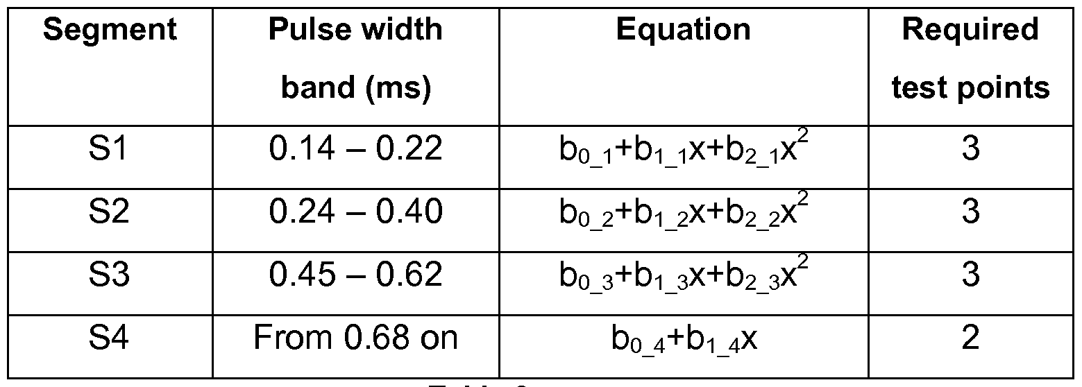
Table 2
These injector specific coefficients by could directly be used in the ECU to control the injection. However, since their determination is based on a reduced number of experimental points, another approach is pre- ferred.
According to a preferred aspect of the present method, an operational performance curve is rebuilt in the ECU based on the master performance curve, stored therein, the latter curve being corrected to take into account the injector specific coefficients. In this embodiment, the master curve is in fact corrected by taking into account the deviation of the injector equation from the equation fitting the master curve.
This is done by adding, for each segment, the master curve to a polynomial of differential coefficients, i.e. a polynomial whose coefficients correspond to the difference between the master coefficients and the injector specific coefficients. For segment S1 , this can be written as:
Operational performance curve = master performance curve +
(Ao+A-|X+A2x2), where
 and x is the band width.
Hence, the performance parameters provided in machine readable format with each injector to be installed in the engine preferably simply comprise this set of differential coefficients for each predetermined segment. These parameters can be provided as optically readable indicia, e.g. encoded in a bar code that is applied on the injector itself or on a tag package with the injector. The specific parameters can also be provided on a computer readable medium, and actually in any appropriate form for retrieval by a machine and transfer into the ECU.
Turning now to Fig.3, there is shown the reconstructed operational curve, indicated 12, for the second segment S2 and the third segment S3.
It is to be appreciated that correcting the master curve 10 by the means of a polynomial of the differential coefficients leads to an improved injection control, since the master curve 10 is built from a large amount of data and more reliable than the few test data obtained from the specific injector.
In practice, the master performance curve may be stored in the ECU as a two-dimensional table comprising a predetermined number of pulse width values and fueling values, and this for each required injector. The operational performance curve is then also a two-dimensional table with same pulse width values, but for each pulse width value, a fueling value is computed by adding the fueling value of the master curve to a computed value of equation A0+A x+A2x2.
These calculations are done at injector installation.
The resulting operational performance curve may then be used by in a conventional way by the ECU, i.e. the ECU may look up for a pulse width value corresponding to a desired fuel quantity, as determined for a given load request. As usual, the table look up procedure can use interpolation.
Claims
1 . A method for fuel injector installation in an engine, comprising the steps of:
a) obtaining performance data specific to a particular fuel injec- tor;
b) determining fuel injector parameters specific to said particular fuel injector based on the obtained performance data;
c) associating said fuel injector parameters specific to said particular fuel injector in a machine readable format;
d) installing said fuel injector in an engine and retrieving and transferring the associated fuel injector parameters into a control unit of said engine;
characterized in that
said method involves:
acquiring a predetermined master performance curve based on experimentation,
segmenting said master performance curve, each segment corresponding to a distinct, operating injector pulse width range;
determining for each segment a characteristic equation fitting the segment;
wherein said control unit has stored therein, for each fuel injector to be installed in said engine, a predetermined set of equations that are each associated with a respective segment of said predetermined master performance curve;
wherein said control unit is configured to receive, for each fuel injector to be installed in said engine, coefficients for said set of equations associated with the particular fuel injector; and
wherein said coefficients are comprised in said fuel injector parameters in machine readable format that are associated with said particular fuel injector.
2. The method according to claim 1 , wherein upon transfer of said coefficients into the ECU, an operational performance curve is built based on said stored set of equations and said coefficients.
3. The method according to anyone of the preceding claims, wherein:
the characteristic equation of each segment comprises a polynomial defined by master coefficients;
step b) implies determining, for each segment of the master performance curve, the injector specific coefficients of a polynomial of same order fitting test performance data;
and wherein the fitting information comprised in said fuel injector parameters specific include differential coefficients calculated, for each segment, as the difference between the respective master coefficients and specific coefficients.
4. The method according to claim 3, wherein said predetermined master performance curve is stored in said control unit, and in that upon transfer of said parameters into said control unit, an operational performance curve is built based on said stored master performance curve corrected by the segment specific polynomials using the corresponding differential coefficients.
5. The method according to any one of the preceding claims, wherein said fuel injector parameters are encoded into optically readable indicia or a transportable computer readable medium.
6. The method according to any one of the preceding claims, wherein said fuel injector parameters are encoded into a bar code applied to and/or packaged with said fuel injector.
7. A system for fuel injector installation in an engine, comprising a fuel injector and associated fuel injector parameters specific to said fuel injector provided in a machine readable format;
means for retrieving said fuel injector parameters and for transfer- ring the latter to a control unit of said engine;
wherein said control unit is configured to receive for each fuel injector to be installed in said engine, information relative to a predetermined, stored set of segments of a predetermined master performance curve corresponding to said injector, and
said information relative to said stored set of segments is comprised in said fuel injector parameters in machine readable format that are associated with said particular fuel injector.
Applications Claiming Priority (2)
| Application Number | Priority Date | Filing Date | Title |
|---|---|---|---|
| EP09180036A EP2336534A1 (en) | 2009-12-18 | 2009-12-18 | Method and system for the injector-individual adaptation of the injection time of motor vehicles |
| EP09180036.7 | 2009-12-18 |
Publications (1)
| Publication Number | Publication Date |
|---|---|
| WO2011073147A1 true WO2011073147A1 (en) | 2011-06-23 |
Family
ID=41786123
Family Applications (1)
| Application Number | Title | Priority Date | Filing Date |
|---|---|---|---|
| PCT/EP2010/069539 Ceased WO2011073147A1 (en) | 2009-12-18 | 2010-12-13 | Method and system for installation of fuel injectors specific parameters |
Country Status (2)
| Country | Link |
|---|---|
| EP (1) | EP2336534A1 (en) |
| WO (1) | WO2011073147A1 (en) |
Cited By (4)
| Publication number | Priority date | Publication date | Assignee | Title |
|---|---|---|---|---|
| EP2650518A1 (en) | 2012-04-12 | 2013-10-16 | Delphi Automotive Systems Luxembourg SA | Method of controlling an injection time of a fuel injector |
| EP2685074A1 (en) | 2012-07-13 | 2014-01-15 | Delphi Automotive Systems Luxembourg SA | Fuel injection control in an internal combustion engine |
| EP2706216A1 (en) | 2012-09-07 | 2014-03-12 | Delphi Technologies Holding S.à.r.l. | Method of determining fuel injector characteristics |
| EP2725215A1 (en) | 2012-10-23 | 2014-04-30 | Delphi International Operations Luxembourg S.à r.l. | Method of operating an internal combustion engine |
Families Citing this family (2)
| Publication number | Priority date | Publication date | Assignee | Title |
|---|---|---|---|---|
| CA2796614C (en) * | 2012-11-21 | 2015-01-06 | Westport Power Inc. | Fuel injector calibration and trimming |
| DE102013221242A1 (en) * | 2013-10-21 | 2015-04-23 | Volkswagen Aktiengesellschaft | Method for operating an internal combustion engine |
Citations (6)
| Publication number | Priority date | Publication date | Assignee | Title |
|---|---|---|---|---|
| EP0771942A1 (en) * | 1995-10-30 | 1997-05-07 | Bayerische Motoren Werke Aktiengesellschaft, Patentabteilung AJ-3 | Apparatus for the electronic control of an engine for motor vehicles with an injection valve |
| WO2002044543A2 (en) * | 2000-11-28 | 2002-06-06 | Bombardier Motor Corporation Of America | Method and apparatus for identifying parameters of an engine for assembly and programming |
| EP1526267A2 (en) * | 2003-10-21 | 2005-04-27 | Siemens Aktiengesellschaft | Method and device for compensating the drift of an injector for an internal combustion engine with direct injection |
| DE102004053266A1 (en) * | 2004-11-04 | 2006-05-11 | Robert Bosch Gmbh | Apparatus and method for correcting the injection behavior of an injector |
| EP1691067A2 (en) * | 2005-02-14 | 2006-08-16 | Hitachi, Ltd. | Electromagnetic actuator, fuel injection valve and method of driving the same |
| DE102006009920A1 (en) * | 2006-03-03 | 2007-09-06 | Robert Bosch Gmbh | Determination of individual cylinder correction values of the injection quantity of an internal combustion engine |
-
2009
- 2009-12-18 EP EP09180036A patent/EP2336534A1/en not_active Withdrawn
-
2010
- 2010-12-13 WO PCT/EP2010/069539 patent/WO2011073147A1/en not_active Ceased
Patent Citations (7)
| Publication number | Priority date | Publication date | Assignee | Title |
|---|---|---|---|---|
| EP0771942A1 (en) * | 1995-10-30 | 1997-05-07 | Bayerische Motoren Werke Aktiengesellschaft, Patentabteilung AJ-3 | Apparatus for the electronic control of an engine for motor vehicles with an injection valve |
| WO2002044543A2 (en) * | 2000-11-28 | 2002-06-06 | Bombardier Motor Corporation Of America | Method and apparatus for identifying parameters of an engine for assembly and programming |
| US7136743B2 (en) | 2000-11-28 | 2006-11-14 | Brp Us Inc. | Method and apparatus for identifying parameters of an engine component for assembly and programming |
| EP1526267A2 (en) * | 2003-10-21 | 2005-04-27 | Siemens Aktiengesellschaft | Method and device for compensating the drift of an injector for an internal combustion engine with direct injection |
| DE102004053266A1 (en) * | 2004-11-04 | 2006-05-11 | Robert Bosch Gmbh | Apparatus and method for correcting the injection behavior of an injector |
| EP1691067A2 (en) * | 2005-02-14 | 2006-08-16 | Hitachi, Ltd. | Electromagnetic actuator, fuel injection valve and method of driving the same |
| DE102006009920A1 (en) * | 2006-03-03 | 2007-09-06 | Robert Bosch Gmbh | Determination of individual cylinder correction values of the injection quantity of an internal combustion engine |
Cited By (7)
| Publication number | Priority date | Publication date | Assignee | Title |
|---|---|---|---|---|
| EP2650518A1 (en) | 2012-04-12 | 2013-10-16 | Delphi Automotive Systems Luxembourg SA | Method of controlling an injection time of a fuel injector |
| WO2013153002A1 (en) | 2012-04-12 | 2013-10-17 | Delphi Automotive Systems Luxembourg Sa. | Method of controlling an injection time of a fuel injector |
| EP2685074A1 (en) | 2012-07-13 | 2014-01-15 | Delphi Automotive Systems Luxembourg SA | Fuel injection control in an internal combustion engine |
| US9863357B2 (en) | 2012-07-13 | 2018-01-09 | Delphi Automotive Systems Luxembourg Sa | Fuel injection control in an internal combustion engine |
| EP2706216A1 (en) | 2012-09-07 | 2014-03-12 | Delphi Technologies Holding S.à.r.l. | Method of determining fuel injector characteristics |
| EP2725215A1 (en) | 2012-10-23 | 2014-04-30 | Delphi International Operations Luxembourg S.à r.l. | Method of operating an internal combustion engine |
| US10054071B2 (en) | 2012-10-23 | 2018-08-21 | Delphi Technologies Ip Limited | Method of operating an internal combustion engine |
Also Published As
| Publication number | Publication date |
|---|---|
| EP2336534A1 (en) | 2011-06-22 |
Similar Documents
| Publication | Publication Date | Title |
|---|---|---|
| WO2011073147A1 (en) | Method and system for installation of fuel injectors specific parameters | |
| US6678606B2 (en) | Tamper detection for vehicle controller | |
| US8412440B2 (en) | Pressure sensor failure diagnosis method and common rail type fuel injection control apparatus | |
| US9075686B2 (en) | System and method to improve control module reflash time | |
| US7628146B2 (en) | Device and method for correcting the injection behavior of an injector | |
| CN101855437B (en) | Method and apparatus for performing both adaptation and diagnosis on an emission-related control device in a vehicle | |
| CN105354140A (en) | Automation testing method and system | |
| CN103314204B (en) | Adaptive Method for Injectors of Internal Combustion Engines | |
| CN101504545B (en) | Diagnostic system and method for detecting tampering of vehicle software or calibrations | |
| DE102013203943A1 (en) | Apparatus, method and system for processing data of a vehicle | |
| US6360161B1 (en) | Method and system for fuel injector coefficient installation | |
| US8775058B2 (en) | Method for the injector-individual adaption of the injection time of motor vehicles | |
| EP2471020B1 (en) | Tampering detection method | |
| GB2533104A (en) | Method of aquiring fuel injector characteristics | |
| CN103635678B (en) | Method for driving an internal combustion engine and internal combustion engine | |
| US20070163543A1 (en) | Method for synchronizing cylinders in terms of quantities of fuel injected in an internal combustion engine | |
| US20130306027A1 (en) | Method for operating an internal combustion engine and control device for this | |
| CN101270697B (en) | Airflow correction learning using electronic throttle control | |
| EP2410160B1 (en) | Method of providing trim data for a fuel injection device | |
| US7962273B2 (en) | Engine control and method for determining the pressure in a combustion chamber of an internal combustion engine | |
| US20160131067A1 (en) | Automated Assembly of ECU Calibrations | |
| CN103717881A (en) | Glow plug drive control method and glow plug drive control device | |
| JP5111486B2 (en) | Update apparatus and update method for control program | |
| CN110032341A (en) | A kind of data processing method, device, electronic equipment and the medium of mould group | |
| CN100412341C (en) | Method and device for controlling an internal combustion engine |
Legal Events
| Date | Code | Title | Description |
|---|---|---|---|
| 121 | Ep: the epo has been informed by wipo that ep was designated in this application |
Ref document number: 10787802 Country of ref document: EP Kind code of ref document: A1 |
|
| NENP | Non-entry into the national phase |
Ref country code: DE |
|
| 122 | Ep: pct application non-entry in european phase |
Ref document number: 10787802 Country of ref document: EP Kind code of ref document: A1 |