WO2011074320A1 - 摺動部材の製造方法と摺動部材 - Google Patents
摺動部材の製造方法と摺動部材 Download PDFInfo
- Publication number
- WO2011074320A1 WO2011074320A1 PCT/JP2010/068284 JP2010068284W WO2011074320A1 WO 2011074320 A1 WO2011074320 A1 WO 2011074320A1 JP 2010068284 W JP2010068284 W JP 2010068284W WO 2011074320 A1 WO2011074320 A1 WO 2011074320A1
- Authority
- WO
- WIPO (PCT)
- Prior art keywords
- alloy layer
- sintered alloy
- sliding member
- recess
- metal
- Prior art date
- Legal status (The legal status is an assumption and is not a legal conclusion. Google has not performed a legal analysis and makes no representation as to the accuracy of the status listed.)
- Ceased
Links
Images

Classifications
-
- B—PERFORMING OPERATIONS; TRANSPORTING
- B22—CASTING; POWDER METALLURGY
- B22F—WORKING METALLIC POWDER; MANUFACTURE OF ARTICLES FROM METALLIC POWDER; MAKING METALLIC POWDER; APPARATUS OR DEVICES SPECIALLY ADAPTED FOR METALLIC POWDER
- B22F7/00—Manufacture of composite layers, workpieces, or articles, comprising metallic powder, by sintering the powder, with or without compacting wherein at least one part is obtained by sintering or compression
- B22F7/02—Manufacture of composite layers, workpieces, or articles, comprising metallic powder, by sintering the powder, with or without compacting wherein at least one part is obtained by sintering or compression of composite layers
- B22F7/04—Manufacture of composite layers, workpieces, or articles, comprising metallic powder, by sintering the powder, with or without compacting wherein at least one part is obtained by sintering or compression of composite layers with one or more layers not made from powder, e.g. made from solid metal
-
- B—PERFORMING OPERATIONS; TRANSPORTING
- B22—CASTING; POWDER METALLURGY
- B22F—WORKING METALLIC POWDER; MANUFACTURE OF ARTICLES FROM METALLIC POWDER; MAKING METALLIC POWDER; APPARATUS OR DEVICES SPECIALLY ADAPTED FOR METALLIC POWDER
- B22F3/00—Manufacture of workpieces or articles from metallic powder characterised by the manner of compacting or sintering; Apparatus specially adapted therefor ; Presses and furnaces
- B22F3/10—Sintering only
-
- B—PERFORMING OPERATIONS; TRANSPORTING
- B22—CASTING; POWDER METALLURGY
- B22F—WORKING METALLIC POWDER; MANUFACTURE OF ARTICLES FROM METALLIC POWDER; MAKING METALLIC POWDER; APPARATUS OR DEVICES SPECIALLY ADAPTED FOR METALLIC POWDER
- B22F3/00—Manufacture of workpieces or articles from metallic powder characterised by the manner of compacting or sintering; Apparatus specially adapted therefor ; Presses and furnaces
- B22F3/10—Sintering only
- B22F3/105—Sintering only by using electric current other than for infrared radiant energy, laser radiation or plasma ; by ultrasonic bonding
-
- B—PERFORMING OPERATIONS; TRANSPORTING
- B22—CASTING; POWDER METALLURGY
- B22F—WORKING METALLIC POWDER; MANUFACTURE OF ARTICLES FROM METALLIC POWDER; MAKING METALLIC POWDER; APPARATUS OR DEVICES SPECIALLY ADAPTED FOR METALLIC POWDER
- B22F3/00—Manufacture of workpieces or articles from metallic powder characterised by the manner of compacting or sintering; Apparatus specially adapted therefor ; Presses and furnaces
- B22F3/12—Both compacting and sintering
- B22F3/16—Both compacting and sintering in successive or repeated steps
- B22F3/162—Machining, working after consolidation
-
- B—PERFORMING OPERATIONS; TRANSPORTING
- B22—CASTING; POWDER METALLURGY
- B22F—WORKING METALLIC POWDER; MANUFACTURE OF ARTICLES FROM METALLIC POWDER; MAKING METALLIC POWDER; APPARATUS OR DEVICES SPECIALLY ADAPTED FOR METALLIC POWDER
- B22F3/00—Manufacture of workpieces or articles from metallic powder characterised by the manner of compacting or sintering; Apparatus specially adapted therefor ; Presses and furnaces
- B22F3/24—After-treatment of workpieces or articles
-
- B—PERFORMING OPERATIONS; TRANSPORTING
- B22—CASTING; POWDER METALLURGY
- B22F—WORKING METALLIC POWDER; MANUFACTURE OF ARTICLES FROM METALLIC POWDER; MAKING METALLIC POWDER; APPARATUS OR DEVICES SPECIALLY ADAPTED FOR METALLIC POWDER
- B22F7/00—Manufacture of composite layers, workpieces, or articles, comprising metallic powder, by sintering the powder, with or without compacting wherein at least one part is obtained by sintering or compression
- B22F7/06—Manufacture of composite layers, workpieces, or articles, comprising metallic powder, by sintering the powder, with or without compacting wherein at least one part is obtained by sintering or compression of composite workpieces or articles from parts, e.g. to form tipped tools
- B22F7/08—Manufacture of composite layers, workpieces, or articles, comprising metallic powder, by sintering the powder, with or without compacting wherein at least one part is obtained by sintering or compression of composite workpieces or articles from parts, e.g. to form tipped tools with one or more parts not made from powder
-
- B—PERFORMING OPERATIONS; TRANSPORTING
- B32—LAYERED PRODUCTS
- B32B—LAYERED PRODUCTS, i.e. PRODUCTS BUILT-UP OF STRATA OF FLAT OR NON-FLAT, e.g. CELLULAR OR HONEYCOMB, FORM
- B32B15/00—Layered products comprising a layer of metal
- B32B15/01—Layered products comprising a layer of metal all layers being exclusively metallic
-
- B—PERFORMING OPERATIONS; TRANSPORTING
- B32—LAYERED PRODUCTS
- B32B—LAYERED PRODUCTS, i.e. PRODUCTS BUILT-UP OF STRATA OF FLAT OR NON-FLAT, e.g. CELLULAR OR HONEYCOMB, FORM
- B32B3/00—Layered products comprising a layer with external or internal discontinuities or unevennesses, or a layer of non-planar shape; Layered products comprising a layer having particular features of form
- B32B3/26—Layered products comprising a layer with external or internal discontinuities or unevennesses, or a layer of non-planar shape; Layered products comprising a layer having particular features of form characterised by a particular shape of the outline of the cross-section of a continuous layer; characterised by a layer with cavities or internal voids ; characterised by an apertured layer
- B32B3/30—Layered products comprising a layer with external or internal discontinuities or unevennesses, or a layer of non-planar shape; Layered products comprising a layer having particular features of form characterised by a particular shape of the outline of the cross-section of a continuous layer; characterised by a layer with cavities or internal voids ; characterised by an apertured layer characterised by a layer formed with recesses or projections, e.g. hollows, grooves, protuberances, ribs
-
- F—MECHANICAL ENGINEERING; LIGHTING; HEATING; WEAPONS; BLASTING
- F16—ENGINEERING ELEMENTS AND UNITS; GENERAL MEASURES FOR PRODUCING AND MAINTAINING EFFECTIVE FUNCTIONING OF MACHINES OR INSTALLATIONS; THERMAL INSULATION IN GENERAL
- F16C—SHAFTS; FLEXIBLE SHAFTS; ELEMENTS OR CRANKSHAFT MECHANISMS; ROTARY BODIES OTHER THAN GEARING ELEMENTS; BEARINGS
- F16C33/00—Parts of bearings; Special methods for making bearings or parts thereof
- F16C33/02—Parts of sliding-contact bearings
-
- F—MECHANICAL ENGINEERING; LIGHTING; HEATING; WEAPONS; BLASTING
- F16—ENGINEERING ELEMENTS AND UNITS; GENERAL MEASURES FOR PRODUCING AND MAINTAINING EFFECTIVE FUNCTIONING OF MACHINES OR INSTALLATIONS; THERMAL INSULATION IN GENERAL
- F16C—SHAFTS; FLEXIBLE SHAFTS; ELEMENTS OR CRANKSHAFT MECHANISMS; ROTARY BODIES OTHER THAN GEARING ELEMENTS; BEARINGS
- F16C33/00—Parts of bearings; Special methods for making bearings or parts thereof
- F16C33/02—Parts of sliding-contact bearings
- F16C33/04—Brasses; Bushes; Linings
- F16C33/06—Sliding surface mainly made of metal
- F16C33/10—Construction relative to lubrication
- F16C33/1025—Construction relative to lubrication with liquid, e.g. oil, as lubricant
- F16C33/103—Construction relative to lubrication with liquid, e.g. oil, as lubricant retained in or near the bearing
-
- F—MECHANICAL ENGINEERING; LIGHTING; HEATING; WEAPONS; BLASTING
- F16—ENGINEERING ELEMENTS AND UNITS; GENERAL MEASURES FOR PRODUCING AND MAINTAINING EFFECTIVE FUNCTIONING OF MACHINES OR INSTALLATIONS; THERMAL INSULATION IN GENERAL
- F16C—SHAFTS; FLEXIBLE SHAFTS; ELEMENTS OR CRANKSHAFT MECHANISMS; ROTARY BODIES OTHER THAN GEARING ELEMENTS; BEARINGS
- F16C33/00—Parts of bearings; Special methods for making bearings or parts thereof
- F16C33/02—Parts of sliding-contact bearings
- F16C33/04—Brasses; Bushes; Linings
- F16C33/06—Sliding surface mainly made of metal
- F16C33/12—Structural composition; Use of special materials or surface treatments, e.g. for rust-proofing
- F16C33/122—Multilayer structures of sleeves, washers or liners
- F16C33/124—Details of overlays
-
- F—MECHANICAL ENGINEERING; LIGHTING; HEATING; WEAPONS; BLASTING
- F16—ENGINEERING ELEMENTS AND UNITS; GENERAL MEASURES FOR PRODUCING AND MAINTAINING EFFECTIVE FUNCTIONING OF MACHINES OR INSTALLATIONS; THERMAL INSULATION IN GENERAL
- F16C—SHAFTS; FLEXIBLE SHAFTS; ELEMENTS OR CRANKSHAFT MECHANISMS; ROTARY BODIES OTHER THAN GEARING ELEMENTS; BEARINGS
- F16C33/00—Parts of bearings; Special methods for making bearings or parts thereof
- F16C33/02—Parts of sliding-contact bearings
- F16C33/04—Brasses; Bushes; Linings
- F16C33/06—Sliding surface mainly made of metal
- F16C33/14—Special methods of manufacture; Running-in
-
- B—PERFORMING OPERATIONS; TRANSPORTING
- B22—CASTING; POWDER METALLURGY
- B22F—WORKING METALLIC POWDER; MANUFACTURE OF ARTICLES FROM METALLIC POWDER; MAKING METALLIC POWDER; APPARATUS OR DEVICES SPECIALLY ADAPTED FOR METALLIC POWDER
- B22F3/00—Manufacture of workpieces or articles from metallic powder characterised by the manner of compacting or sintering; Apparatus specially adapted therefor ; Presses and furnaces
- B22F3/10—Sintering only
- B22F3/105—Sintering only by using electric current other than for infrared radiant energy, laser radiation or plasma ; by ultrasonic bonding
- B22F2003/1054—Sintering only by using electric current other than for infrared radiant energy, laser radiation or plasma ; by ultrasonic bonding by microwave
-
- B—PERFORMING OPERATIONS; TRANSPORTING
- B22—CASTING; POWDER METALLURGY
- B22F—WORKING METALLIC POWDER; MANUFACTURE OF ARTICLES FROM METALLIC POWDER; MAKING METALLIC POWDER; APPARATUS OR DEVICES SPECIALLY ADAPTED FOR METALLIC POWDER
- B22F7/00—Manufacture of composite layers, workpieces, or articles, comprising metallic powder, by sintering the powder, with or without compacting wherein at least one part is obtained by sintering or compression
- B22F7/02—Manufacture of composite layers, workpieces, or articles, comprising metallic powder, by sintering the powder, with or without compacting wherein at least one part is obtained by sintering or compression of composite layers
- B22F7/04—Manufacture of composite layers, workpieces, or articles, comprising metallic powder, by sintering the powder, with or without compacting wherein at least one part is obtained by sintering or compression of composite layers with one or more layers not made from powder, e.g. made from solid metal
- B22F2007/042—Manufacture of composite layers, workpieces, or articles, comprising metallic powder, by sintering the powder, with or without compacting wherein at least one part is obtained by sintering or compression of composite layers with one or more layers not made from powder, e.g. made from solid metal characterised by the layer forming method
- B22F2007/047—Manufacture of composite layers, workpieces, or articles, comprising metallic powder, by sintering the powder, with or without compacting wherein at least one part is obtained by sintering or compression of composite layers with one or more layers not made from powder, e.g. made from solid metal characterised by the layer forming method non-pressurised baking of the paste or slurry containing metal powder
-
- B—PERFORMING OPERATIONS; TRANSPORTING
- B22—CASTING; POWDER METALLURGY
- B22F—WORKING METALLIC POWDER; MANUFACTURE OF ARTICLES FROM METALLIC POWDER; MAKING METALLIC POWDER; APPARATUS OR DEVICES SPECIALLY ADAPTED FOR METALLIC POWDER
- B22F2302/00—Metal Compound, non-Metallic compound or non-metal composition of the powder or its coating
- B22F2302/45—Others, including non-metals
-
- B—PERFORMING OPERATIONS; TRANSPORTING
- B22—CASTING; POWDER METALLURGY
- B22F—WORKING METALLIC POWDER; MANUFACTURE OF ARTICLES FROM METALLIC POWDER; MAKING METALLIC POWDER; APPARATUS OR DEVICES SPECIALLY ADAPTED FOR METALLIC POWDER
- B22F2998/00—Supplementary information concerning processes or compositions relating to powder metallurgy
- B22F2998/10—Processes characterised by the sequence of their steps
-
- F—MECHANICAL ENGINEERING; LIGHTING; HEATING; WEAPONS; BLASTING
- F16—ENGINEERING ELEMENTS AND UNITS; GENERAL MEASURES FOR PRODUCING AND MAINTAINING EFFECTIVE FUNCTIONING OF MACHINES OR INSTALLATIONS; THERMAL INSULATION IN GENERAL
- F16C—SHAFTS; FLEXIBLE SHAFTS; ELEMENTS OR CRANKSHAFT MECHANISMS; ROTARY BODIES OTHER THAN GEARING ELEMENTS; BEARINGS
- F16C2202/00—Solid materials defined by their properties
- F16C2202/02—Mechanical properties
- F16C2202/04—Hardness
-
- F—MECHANICAL ENGINEERING; LIGHTING; HEATING; WEAPONS; BLASTING
- F16—ENGINEERING ELEMENTS AND UNITS; GENERAL MEASURES FOR PRODUCING AND MAINTAINING EFFECTIVE FUNCTIONING OF MACHINES OR INSTALLATIONS; THERMAL INSULATION IN GENERAL
- F16C—SHAFTS; FLEXIBLE SHAFTS; ELEMENTS OR CRANKSHAFT MECHANISMS; ROTARY BODIES OTHER THAN GEARING ELEMENTS; BEARINGS
- F16C2220/00—Shaping
- F16C2220/20—Shaping by sintering pulverised material, e.g. powder metallurgy
-
- F—MECHANICAL ENGINEERING; LIGHTING; HEATING; WEAPONS; BLASTING
- F16—ENGINEERING ELEMENTS AND UNITS; GENERAL MEASURES FOR PRODUCING AND MAINTAINING EFFECTIVE FUNCTIONING OF MACHINES OR INSTALLATIONS; THERMAL INSULATION IN GENERAL
- F16C—SHAFTS; FLEXIBLE SHAFTS; ELEMENTS OR CRANKSHAFT MECHANISMS; ROTARY BODIES OTHER THAN GEARING ELEMENTS; BEARINGS
- F16C2220/00—Shaping
- F16C2220/60—Shaping by removing material, e.g. machining
- F16C2220/70—Shaping by removing material, e.g. machining by grinding
-
- F—MECHANICAL ENGINEERING; LIGHTING; HEATING; WEAPONS; BLASTING
- F16—ENGINEERING ELEMENTS AND UNITS; GENERAL MEASURES FOR PRODUCING AND MAINTAINING EFFECTIVE FUNCTIONING OF MACHINES OR INSTALLATIONS; THERMAL INSULATION IN GENERAL
- F16C—SHAFTS; FLEXIBLE SHAFTS; ELEMENTS OR CRANKSHAFT MECHANISMS; ROTARY BODIES OTHER THAN GEARING ELEMENTS; BEARINGS
- F16C2220/00—Shaping
- F16C2220/80—Shaping by separating parts, e.g. by severing, cracking
- F16C2220/82—Shaping by separating parts, e.g. by severing, cracking by cutting
-
- F—MECHANICAL ENGINEERING; LIGHTING; HEATING; WEAPONS; BLASTING
- F16—ENGINEERING ELEMENTS AND UNITS; GENERAL MEASURES FOR PRODUCING AND MAINTAINING EFFECTIVE FUNCTIONING OF MACHINES OR INSTALLATIONS; THERMAL INSULATION IN GENERAL
- F16C—SHAFTS; FLEXIBLE SHAFTS; ELEMENTS OR CRANKSHAFT MECHANISMS; ROTARY BODIES OTHER THAN GEARING ELEMENTS; BEARINGS
- F16C2223/00—Surface treatments; Hardening; Coating
- F16C2223/02—Mechanical treatment, e.g. finishing
- F16C2223/06—Mechanical treatment, e.g. finishing polishing
-
- F—MECHANICAL ENGINEERING; LIGHTING; HEATING; WEAPONS; BLASTING
- F16—ENGINEERING ELEMENTS AND UNITS; GENERAL MEASURES FOR PRODUCING AND MAINTAINING EFFECTIVE FUNCTIONING OF MACHINES OR INSTALLATIONS; THERMAL INSULATION IN GENERAL
- F16C—SHAFTS; FLEXIBLE SHAFTS; ELEMENTS OR CRANKSHAFT MECHANISMS; ROTARY BODIES OTHER THAN GEARING ELEMENTS; BEARINGS
- F16C2223/00—Surface treatments; Hardening; Coating
- F16C2223/02—Mechanical treatment, e.g. finishing
- F16C2223/08—Mechanical treatment, e.g. finishing shot-peening, blasting
-
- F—MECHANICAL ENGINEERING; LIGHTING; HEATING; WEAPONS; BLASTING
- F16—ENGINEERING ELEMENTS AND UNITS; GENERAL MEASURES FOR PRODUCING AND MAINTAINING EFFECTIVE FUNCTIONING OF MACHINES OR INSTALLATIONS; THERMAL INSULATION IN GENERAL
- F16C—SHAFTS; FLEXIBLE SHAFTS; ELEMENTS OR CRANKSHAFT MECHANISMS; ROTARY BODIES OTHER THAN GEARING ELEMENTS; BEARINGS
- F16C2223/00—Surface treatments; Hardening; Coating
- F16C2223/10—Hardening, e.g. carburizing, carbo-nitriding
-
- F—MECHANICAL ENGINEERING; LIGHTING; HEATING; WEAPONS; BLASTING
- F16—ENGINEERING ELEMENTS AND UNITS; GENERAL MEASURES FOR PRODUCING AND MAINTAINING EFFECTIVE FUNCTIONING OF MACHINES OR INSTALLATIONS; THERMAL INSULATION IN GENERAL
- F16C—SHAFTS; FLEXIBLE SHAFTS; ELEMENTS OR CRANKSHAFT MECHANISMS; ROTARY BODIES OTHER THAN GEARING ELEMENTS; BEARINGS
- F16C2223/00—Surface treatments; Hardening; Coating
- F16C2223/30—Coating surfaces
- F16C2223/32—Coating surfaces by attaching pre-existing layers, e.g. resin sheets or foils by adhesion to a substrate; Laminating
-
- F—MECHANICAL ENGINEERING; LIGHTING; HEATING; WEAPONS; BLASTING
- F16—ENGINEERING ELEMENTS AND UNITS; GENERAL MEASURES FOR PRODUCING AND MAINTAINING EFFECTIVE FUNCTIONING OF MACHINES OR INSTALLATIONS; THERMAL INSULATION IN GENERAL
- F16C—SHAFTS; FLEXIBLE SHAFTS; ELEMENTS OR CRANKSHAFT MECHANISMS; ROTARY BODIES OTHER THAN GEARING ELEMENTS; BEARINGS
- F16C2226/00—Joining parts; Fastening; Assembling or mounting parts
- F16C2226/10—Force connections, e.g. clamping
- F16C2226/12—Force connections, e.g. clamping by press-fit, e.g. plug-in
-
- Y—GENERAL TAGGING OF NEW TECHNOLOGICAL DEVELOPMENTS; GENERAL TAGGING OF CROSS-SECTIONAL TECHNOLOGIES SPANNING OVER SEVERAL SECTIONS OF THE IPC; TECHNICAL SUBJECTS COVERED BY FORMER USPC CROSS-REFERENCE ART COLLECTIONS [XRACs] AND DIGESTS
- Y10—TECHNICAL SUBJECTS COVERED BY FORMER USPC
- Y10T—TECHNICAL SUBJECTS COVERED BY FORMER US CLASSIFICATION
- Y10T428/00—Stock material or miscellaneous articles
- Y10T428/12—All metal or with adjacent metals
- Y10T428/12014—All metal or with adjacent metals having metal particles
- Y10T428/12028—Composite; i.e., plural, adjacent, spatially distinct metal components [e.g., layers, etc.]
- Y10T428/12063—Nonparticulate metal component
Definitions
- the present invention relates to a sliding member manufacturing method and a sliding member. More specifically, the present invention relates to a sliding member manufacturing method in which a large number of indents are formed on a sliding surface, and a sliding manufactured by the manufacturing method. It relates to members.
- Patent Document 1 a slide bearing having a large number of recesses (indents) as oil reservoirs on a sliding surface has been proposed (for example, Patent Document 1).
- Patent Document 2 a slide bearing having a large number of recesses (indents) as oil reservoirs on a sliding surface has been proposed (for example, Patent Document 1).
- Patent Document 2 the manufacturing method of Patent Document 1, when the concave portion is formed on the sliding surface of the sliding member, the bottom portion of the concave portion and the surrounding metal structure are layered and work hardening occurs, so that the bottom portion of the concave portion is cracked. There was a problem that occurred. Accordingly, the applicant of the present application has proposed a method for manufacturing a sliding member that is less likely to crack at the bottom of the concave portion when the concave portion is formed on the sliding surface in consideration of the problems of Patent Document 1. Yes (Patent Document 2).
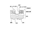
- Patent Literature 2 can eliminate the above-mentioned drawbacks related to Patent Literature 1, but the following disadvantages are present. It turned out to be. That is, as shown in the schematic diagram of the cross section in FIG. 6, when a large number of recesses are formed in the sintered alloy layer of the sliding member, the position of the back surface (back surface of the back metal) of the sliding member corresponding to each recess. In this case, a minute convex portion is generated.
- the present invention provides a sintered alloy layer that is laminated on the surface of a back metal and a manufacturing method of a sliding member that includes a large number of recesses formed on the surface of the sintered alloy layer.
- a primary sintering process is performed on the metal powder to form a sintered alloy layer on the surface of the back metal, and then the back metal is formed.
- a plurality of recesses are formed on the surface of the sintered alloy layer laminated, and then the sintered alloy layer and the back metal having the recesses are rolled, and then the sintered alloy layer having the recesses is formed.
- the sliding member is manufactured by performing a secondary sintering process.
- the bulge amount of the convex portions generated on the back surface corresponding to the concave portions is smaller than the manufacturing method of the prior application. . And it can prevent that the edge of each recessed part rises. Therefore, it is possible to simplify the operation of removing the raised portions at the edges of the concave portions and the convex portions generated on the back surface as compared with the conventional one. Therefore, it is possible to provide a method for manufacturing a sliding member that can be easily finished as compared with the prior art.
- the work process figure which shows one Example of this invention.
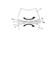
- the front view of the principal part of FIG. The enlarged view of the principal part of FIG.
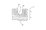
- the schematic diagram which shows the recessed part of the sliding member formed by the present Example, and the cross section of the periphery.
- the schematic diagram which shows the recessed part of the plain bearing formed by the prior art, and the cross section of the periphery.
- FIG. 1 shows a sliding member manufacturing system 1 according to the present invention.
- the present embodiment relates to a manufacturing system 1 of a thin plate-like sliding member 2 used for a sliding bearing and a manufacturing process thereof, but before explaining the manufacturing process of the sliding member 2 by this manufacturing system 1, First, the configuration of the sliding member 2 manufactured by the manufacturing system 1 will be described.
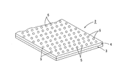
- the sliding member 2 as a product includes a thin plate-like back metal 3 as a base material, and a sintered alloy layer 4 formed by performing a sintering process on the entire surface of the back metal 3. And many hemispherical recessed parts 5 used as the oil reservoir over the whole surface of the sintered alloy layer 4 are formed.
- a thin steel plate material continuous in the longitudinal direction is used, and a sintered alloy layer 4 of a copper-based alloy is formed on the surface (upper surface) of the back metal 3.
- cold rolled steel is used as the material for the back metal 3.
- the back metal 3 a steel material whose surface is previously plated with copper may be used.
- a recess 5 as an oil reservoir formed on the surface of the sintered alloy layer 4 is a hemispherical recess having a diameter of about 3 to 4 mm.
- the plate thickness of the sliding member 2 is assumed to be about 1 to 6 mm.
- a slide bearing formed into a cylindrical shape after the sliding member 2 is cut into a strip having a predetermined dimension is fixed to the housing in a state where the back surface of the back metal 3 serving as the outer peripheral surface is superposed on the housing.
- the surface of the sintered alloy layer 4 serving as the inner peripheral surface is a sliding surface that slides on the shaft member. Since the sintered alloy layer 4 serving as the sliding surface has a large number of recesses 5 as oil reservoirs, the lubricating oil is temporarily stored in the recesses 5 to prevent seizure and wear resistance of the slide bearing. Can be improved.
- the present embodiment is characterized in that, when the sliding member 2 is manufactured, the numerous recesses 5 are formed in the sintered alloy layer 4 immediately after the primary sintering step. As a result, work hardening is suppressed from occurring on the surface and inside of the sintered alloy layer 4 facing the internal space of the concave portion 5, and the amount of protrusion of the convex portion generated on the back surface corresponding to each concave portion 5 is reduced. Is.
- the manufacturing process by the manufacturing system 1 of a present Example is demonstrated. First, the thin plate-like back metal 3 wound around the roll member 6 is pulled out by a mechanism (not shown) and then supplied to the adjacent downstream-side sintered material spraying mechanism 11.
- the sintered material spraying mechanism 11 sprays lead and copper powders as materials of the sintered alloy layer 4 over the entire surface (the entire top surface) of the back metal 3. (Spraying process).
- the sintered material spraying mechanism 11 sprays lead and copper powders as materials of the sintered alloy layer 4 over the entire surface (the entire top surface) of the back metal 3. (Spraying process).
- only one kind of Cu—Sn—Bi alloy metal powder is dispersed as the metal powder used as the material of the sintered alloy layer 4, but two or more kinds of metal powders (for example, Cu powder and Sn powder) are dispersed. And Bi powder) may be sprayed.
- the back metal 3 on which the powder of the metal material to be the sintered alloy layer 4 is spread on the surface in this manner is then fed into the first sintering mechanism 12 and then transferred toward the downstream side as required. Heated to temperature. Thereby, the sintered alloy layer 4 is formed in the whole surface of the back metal 3 (primary sintering process).
- primary sintering method and mechanism so far, conventionally known methods such as electric furnace sintering and high frequency sintering can be used.
- the back metal 3 is heated while being transferred through the inside of the first sintering mechanism 12, so that the sintered alloy layer 4 is formed on the surface, and then the back metal 3 and the surface of the back metal 3 are laminated on the surface.
- the sintered alloy layer 4 is supplied to the intermediate rolling mechanism 13. Note that after the primary sintering process, the back metal 3 and the sintered alloy layer 4 may be cooled to a required temperature and then supplied to the intermediate rolling mechanism 13.
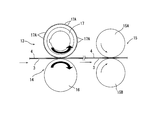
- the intermediate rolling mechanism 13 of the present embodiment is disposed at a position downstream of the first sintering mechanism 12 and forms a large number of recesses 5 on the surface of the sintered alloy layer 4, and the recess forming mechanism. 14 and the rolling roll 15 arrange
- the recess forming mechanism 14 has a rotating roller 16 on the lower side having a smooth outer peripheral surface having no irregularities and a large number of forming pins 17 ⁇ / b> A arranged in the radial direction over the entire outer peripheral surface.
- the downstream rolling roll 15 is provided with a pair of upper and lower rotating rolls 15A and 15B, which are rotated in synchronization with the arrow direction.
- the sintered alloy layer 4 and the back metal 3 in which the recess 5 is formed are fed from the recess forming mechanism 14 to the rolling roll 15, the sintered alloy layer 4 and the back metal 3 are rolled by the rotating rolls 15 ⁇ / b> A and 15 ⁇ / b> B of the rolling roll 15. Then, it is sent out to the secondary sintering mechanism 21 at the adjacent position.
- a large number of recesses 5 as oil sumps are formed in the sintered alloy layer 4 by the recess forming mechanism 14, and then a large number of recesses 5 are formed.
- the sintered alloy layer 4 and the back metal 3 are rolled by a rolling roll 15 and then fed into the second sintering mechanism 21.
- a large number of recesses 5 are formed in the sintered alloy layer 4 at an unstructured stage after the primary sintering process, so that work hardening occurs in the recesses 5 and the periphery thereof. I try to suppress it.
- the back metal 3 and the sintered alloy layer 4 are heated again by the second sintering mechanism 21 to be subjected to a final sintering process (secondary sintering process).
- secondary sintering process a final sintering process
- the said sliding member 2 as a product shown in FIG. 2 is manufactured.
- the sliding member 2 as this product is wound up by the winding roll 22 arrange
- finish processing such as sanding may be applied to the sintered alloy layer 4.
- a conventionally well-known mechanism can be utilized regarding the said secondary sintering process and the process after it.
- the sintered alloy layer 4 is formed by the concave forming mechanism 14 immediately after the sintered alloy layer 4 is formed on the surface of the back metal 3 by the primary sintering process. A large number of recesses 5 are formed on the surface. After that, the sintered alloy layer 4 and the back metal 3 are rolled by a rolling roll 15. In other words, before the finish sintering process is performed by the second sintering mechanism 21 and before the rolling by the rolling roll 15, the above-described numerous recesses 5 are formed on the surface of the sintered alloy layer 4. . Thereby, in a present Example, it can suppress that work hardening arises in the location of each recessed part 5 and the inside of the sintered alloy layer 4 in the sliding member 2 as a product.
- FIG. 5 is a schematic view showing a cross section of the sliding member 2 as a product according to this embodiment.
- the sintered alloy layer 4 of the sliding member 2 has a matrix structure in which lead or copper, which is a metal structure, is dispersed in a granular form without being layered.
- the concave portion 5 and its periphery (the surface and the inside of the sintered alloy layer 4 facing the internal space in the concave portion 5) in the sintered alloy layer 4 are granular without the metal structure being layered. No work hardening occurs. Therefore, cracks are unlikely to occur at the bottom of the recess 5 and its periphery.
- the reason why the raised portion does not occur in the edge 5A in this embodiment is considered as follows. That is, in this embodiment, since the structure constituting the sintered alloy layer 4 remains granular, a minute gap remains between the particles of the structure. Therefore, as described above, in the step of forming the numerous recesses 5 in the sintered alloy layer 4, when the forming pin 17A is pushed into the sintered alloy layer 4 from the surface side to compress the tissue particles, The gap serves as a place for particles to escape.
- the sintered alloy layer after the rolling process has a layered structure and almost no gaps between the particles of the structure. Therefore, when the forming pin is pushed into the sintered alloy layer after the rolling process to form a recess, the layered particles in the sintered alloy layer have no escape, so the force to push the forming pin into the sintered alloy layer Will not be absorbed. Therefore, in the prior art, it is considered that a raised portion is formed at the edge of the recess. Further, the bulging amount ⁇ of the convex portion generated on the back surface of the back metal corresponding to the concave portion is more than doubled as compared with the present embodiment.
- this sliding member since the hardened raised portion is generated at the edge of the recessed portion in the sintered alloy layer, when finishing the surface of the sintered alloy layer, the edge of the recessed portion is formed. Cracks and chipping sometimes occurred at the bulge.
- the work hardening of the sintered alloy layer 4 can be suppressed as compared with the prior art, and the bulging amount ⁇ of the convex portion 3A generated on the back surface of the back metal 3 can be reduced.
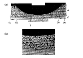
- FIGS. 7A and 7B are cross-sectional photographs of the recess 5 and its periphery in the sliding member 2 of this embodiment.
- FIG. 7A shows the cross section enlarged 50 times
- FIG. 7B shows the central part of the cross section enlarged 100 times.
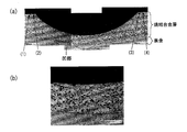
- FIG. 8A and FIG. 8B are cross-sectional photographs of the concave portion of the sliding member manufactured by the conventional technique of Patent Document 2 and the periphery thereof.
- FIG. 8A shows the cross section enlarged 50 times
- FIG. 7B shows the cross section enlarged 100 times.
- FIG. 8A shows the cross section enlarged 50 times
- FIG. 7B shows the cross section enlarged 100 times.
- the metal structure is scattered in a granular structure not only on the entire surface of the recess 5 in the sintered alloy layer 4 but also on the inner side. That is, it can be understood that work hardening has not occurred at the portion facing the bottom of the recess 5 and the internal space. For this reason, in the present example, no cracks occurred at the locations facing the bottom and internal space of the recess 5.
- the metal structure is scattered in a granular form at the bottom of the concave portion and the vicinity thereof, but the metal structure is not granular and is layered in a region closer to the opening than the bottom and the periphery thereof. Yes. In this prior art as well, no cracks occurred at the bottom of the recess 5.
- the metal structure is layered at the edge of the recess and the inner side and the outer side.
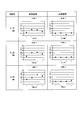
- FIG. 9 shows the results of hardness inspections at four locations (1) to (4) close to the surface of the sliding member shown in FIGS. 7 (a) and 8 (a) formed into a cylindrical shape. Is shown.
- the inspection results in FIG. 9 show the results of the above (1) to (4) when the positions of 0.15 mm, 0.20 mm, and 0.25 mm are cut from the surface side of the sliding member of this example and the prior art.
- the average hardness at each of the four locations was measured.
- the reason for measuring the hardness at the position where the surface of the sliding member was cut in a predetermined amount as described above is that after the cylindrical bush is press-fitted into the housing, the inner peripheral surface thereof is finished by cutting or the like. It is because it is often done.
- the hardness of the portion (2), (3) that becomes the edge of the recess was about Hv120, but the outer side adjacent to the edge of the recess In the points (1) and (4), the hardness is about Hv100.
- the difference in hardness between the portion serving as the edge of the recess and the adjacent outer portion is approximately Hv25.
- the hardness is about Hv90 or less at all the locations (1) to (4). That is, in the present embodiment, the hardness is substantially the same (the hardness difference is about Hv15 at the maximum) at the edge 5A of the recess 5 and the adjacent outer side thereof, and the hardness is smaller than that of the prior art. .
- the hardness is about Hv 130 to 140 in the places (2) and (3) which become the edge of the recess, whereas the edge Hardness is about Hv100 at the location (1) which is adjacent to the outside, and hardness is about Hv120 at the other location (4). Therefore, the maximum hardness difference is about Hv40.
- the hardness is about Hv90 (the hardness difference is about Hv5 at the maximum) in all the locations (1) to (4).
- the hardness at the portion (2) serving as the edge of the recess is about Hv130, and the hardness at the other location (3) is about Hv150.
- the hardness is about Hv110 at the location (1) that is adjacent to the outside of the edge, and the hardness is about 140 Hv at the location (4) on the opposite side. Therefore, the maximum hardness difference is about Hv40. In contrast, in this embodiment, the hardness is about Hv 90 to 100 (the hardness difference is about Hv 10 at the maximum) at all four locations (1) to (4).
- the edge 5A of the recess 5 and its adjacent outer side are softer than those of the prior art.
- the hardness is substantially uniform. That is, it can be understood that work hardening has not occurred in the present embodiment and work hardening has occurred in the conventional technique.
- FIG. 10 is a comparison between the present embodiment and the prior art with respect to the amount of bulge of the convex portion generated on the back surface corresponding to the concave portion of the sliding member and the number of back processes for deleting the convex portion.
- the back treatment means a treatment such as polishing / grinding performed on the back surface of the sliding member.
- the back treatment is 0 times, that is, a state before the back treatment is performed on the convex portion generated on the back surface of the sliding member.
- the amount of bulging was 16 ⁇ m.
- the bulging amount of the convex portion 3A was 4 ⁇ m.
- FIG. 10 shows a state in which the convex portions are reduced when the back treatment is sequentially performed once, twice, and three times on the back surface of the sliding member of the prior art and this embodiment. That is, in this embodiment shown on the right side in FIG. 10, the convex portion 3A is almost completely deleted by one back process. In contrast, in the conventional technique on the left side in FIG. 10, the convex portion is finally deleted after three back processes.
- the amount of bulging of the convex portion 3A generated on the back surface corresponding to the concave portion 5 is reduced to about a quarter compared to the prior art.
- the number of back processes for deleting the convex portion 3A is sufficient only once. Therefore, according to the present embodiment, the finishing operation process for removing the convex portion 3A generated on the back surface of the sliding member 2 is easier than in the prior art.
- the surface of the sintered alloy layer 4 facing the internal space of each concave portion 5 and the organization of the structure in the inside are prevented and work hardening occurs. Can be suppressed. Therefore, the sliding member 2 is less likely to be cracked at the bottom of the recess 5, and can suppress the lack of the edge 5 ⁇ / b> A of the recess 5 and its periphery. In addition, the edge 5A of the recess 5 does not rise.
- the convex portion 3A generated on the back surface corresponding to the concave portion 5 has a smaller bulge amount than that in the case of the above-described conventional technology, and the finishing work process for removing the convex portion 3A is easy correspondingly. It becomes. Therefore, according to the manufacturing method of the present embodiment, it is possible to provide the sliding member 2 which is lower in manufacturing cost than the conventional one and has excellent sliding performance.
Landscapes
- Engineering & Computer Science (AREA)
- Mechanical Engineering (AREA)
- General Engineering & Computer Science (AREA)
- Manufacturing & Machinery (AREA)
- Chemical & Material Sciences (AREA)
- Composite Materials (AREA)
- Materials Engineering (AREA)
- Oil, Petroleum & Natural Gas (AREA)
- Physics & Mathematics (AREA)
- Optics & Photonics (AREA)
- Sliding-Contact Bearings (AREA)
- Powder Metallurgy (AREA)
Abstract
Description
そこで、本願の出願人は、上記特許文献1の問題点を踏まえた上で、摺動面に凹部を形成した際に該凹部の底部にひび割れが生じにくい摺動部材の製造方法を提案したところである(特許文献2)。
また、各凹部の縁とその隣接部分は層状となって加工硬化が生じ、かつ各凹部の縁部が盛り上がるという問題が発生した。そのため、特許文献2の製造方法においては、摺動部材に凹部を形成した後の工程において、裏面の凸部や各凹部の縁の盛り上がり部分を削除する仕上げ作業が必要となり、その作業に時間とコストが掛かるという問題が生じた。
上記裏金の表面に少なくとも一種以上の金属の粉末を散布した後に、該金属の粉末に1次焼結処理を施して上記裏金の表面に焼結合金層を積層させて形成し、次に上記裏金に積層させた焼結合金層の表面に上記多数の凹部を形成し、次に上記凹部が形成された焼結合金層および裏金を圧延し、その後、上記凹部が形成された焼結合金層に2次焼結処理を施すことにより上記摺動部材を製造するようにしたものである。
裏金3の材料としては長手方向に連続する薄板状の鋼材を用いてあり、この裏金3の表面(上面)に銅系合金の焼結合金層4を形成するようにしている。本実施例においては裏金3の材料として冷間圧延鋼を用いている。なお、裏金3としては、予め表面に銅めっきを施した鋼材を用いても良い。焼結合金層4の表面に形成された油溜りとしての凹部5は、直径3~4mm程度の半球状の窪みとなっている。また、摺動部材2の板厚は1~6mm程度を想定している。
摺動部材2を所定寸法の短冊状に切断してから円筒状に成形されたすべり軸受は、その外周面となる裏金3の裏面がハウジングに重合された状態で、該ハウジングに固定されるとともに、内周面となる焼結合金層4の表面が軸部材と摺動する摺動面となる。そして、摺動面となる焼結合金層4には油溜りとしての多数の凹部5が形成されているので、潤滑油は上記凹部5内に一時貯留されてすべり軸受の耐焼付性及び耐摩耗性を向上させることができるようになっている。
ここで、図1に基づいて本実施例の製造システム1による製造工程を説明する。先ず、ロール部材6に巻き取られた薄板状の裏金3が図示しない機構によって引き出されてから隣接下流側の焼結材散布機構11へ供給されるようになっている。
裏金3が焼結材散布機構11に送り込まれると、この焼結材散布機構11によって裏金3における表面全域(上面全域)にわたって焼結合金層4の材料となる鉛と銅の粉末が散布される(散布工程)。なお、本実施例では焼結合金層4の材料となる金属粉末としてCu-Sn-Bi合金の金属粉末1種類のみを散布しているが、2種類以上の金属粉末(例えばCu粉末とSn粉末とBi粉末)の混合体を散布するようにしてもよい。なお、これはあくまでも一例であり、金属粉末の種類と組合せが上記に限定されないのは勿論である。
このようにして焼結合金層4となる金属材料の粉末が表面に散布された裏金3は、その後、第1焼結機構12の内部へ送り込まれてから下流側に向けて移送されながら所要の温度まで加熱されるようになっている。これにより、裏金3の表面全域に焼結合金層4が形成されるようになっている(1次焼結処理)。なお、ここまでの1次焼結の方法および機構は、電気炉焼結、高周波焼結など従来公知のものを利用することができる。
凹部成形機構14は、図3及び図4に示すように、凹凸のない滑らかな外周面を有する下方側の回転ロール16と、外周面の全域に多数の成形ピン17Aを放射方向に向けて配置した成形ロール17とを備えている。そして、回転ロール16と成形ロール17との間に、前述した焼結合金層4を積層した裏金3が送り込まれると、裏金3および焼結合金層4はそれらの間を通過していき、それに伴って、成形ロール17の多数の成形ピン17Aによって焼結合金層4の表面に半球状をした多数の凹部5が形成されるようになっている。
次に、下流側の圧延ロール15は上下一対の回転ロール15A、15Bを備えており、それらは矢印方向に同期して回転されるようになっている。そして、凹部5が形成された焼結合金層4と裏金3が凹部成形機構14から圧延ロール15に送り込まれると、圧延ロール15の回転ロール15A、15Bによって焼結合金層4および裏金3が圧延され、その後、隣接位置の第2次焼結機構21へ送り出されるようになっている。
そして、この後、裏金3と焼結合金層4はこの第2焼結機構21によって再度加熱されて仕上げ焼結処理(2次焼結処理)が施されるようになっている。
これにより、図2に示した製品としての上記摺動部材2が製造されるようになっている。そして、この製品としての摺動部材2は最も下流側に配置された巻取りロール22に巻き取られるようになっている。
なお、第2焼結機構21による仕上げ焼結処理の後に、裏金3と焼結合金層4を所要温度まで冷却するようにしても良いし、さらにそのような冷却処理を行った後に、裏金3と焼結合金層4に対してサンディング等の仕上げ加工を施しても良い。また、上記2次焼結処理とそれ以降の処理に関しては、従来公知の機構を利用することができる。
このように、本実施例において縁部5Aに盛り上がり部分が生じないのは次のような理由からと考えられる。すなわち、本実施例においては、焼結合金層4を構成する組織が粒状のままとなっているので、それら組織の粒子間に微小な隙間が残存する。そのため、前述したように焼結合金層4に上記多数の凹部5を形成する工程において、表面側から成形ピン17Aが焼結合金層4に押し込まれて組織の粒子を圧縮させる際に上記微小な隙間が粒子の逃げ場となる。そのため、各凹部5の縁部にバリ状の盛り上がり部が形成されないものと考えられる。
しかも、焼結合金層4は加工硬化を起こしていないので、焼結合金4の表面に仕上げ加工を施したときでも凹部5の縁部5Aが欠落することを防止することができる。さらに、本実施例においては、各凹部5と対応する裏金3の裏面の箇所に生じる凸部3Aの膨出量αも小さくなる。よって、製造されたすべり軸受の裏金に生じる膨出量αも小さくなる。
また、凹部と対応する裏金の裏面に生じた凸部の膨出量αは本実施例と比較すると倍以上に大きくなる。そのため、この従来技術による摺動部材においては、裏面の凸部や表面のバリ状の盛り上がり部を除去するため仕上げ作業に時間を要することになる。しかも、前述したように、焼結合金層における凹部の縁部には硬くなった盛り上がり部が生じているため、焼結合金層の表面に仕上げ加工を施した場合には、凹部の縁部の盛り上がり部に割れやカケが生じることがあった。
換言すると、本実施例においては、従来技術と比較すると焼結合金層4の加工硬化を抑制することができ、裏金3の裏面に生じる凸部3Aの膨出量αを小さくすることができる。そのため、本実施例においては、裏金3の裏面に生じた凸部3Aの除去作業を行うだけでよく、その作業時間も従来技術と比較して凸部の膨出量αが小さい分だけ簡単なものとなる。
図7(a)、(b)は、本実施例の摺動部材2における凹部5とその周辺の断面写真である。図7(a)は断面を50倍に拡大したものであり、図7(b)は断面の中央部分を100倍に拡大したものである。
他方、図8(a)、(b)は、上記特許文献2の従来技術によって製造した摺動部材の凹部とその周辺の断面写真である。図8(a)は断面を50倍に拡大したものであり、図7(b)は断面の中央部分を100倍に拡大したものである。
図7に示す本実施例においては、焼結合金層4における凹部5の表面全域だけでなく内部側においても金属組織が粒状に散在してマトリックス構造となっている。つまり、凹部5の底部および内部空間に臨む箇所には加工硬化は生じていないことが理解できる。そのため、本実施例においては、凹部5の底部および内部空間に臨む箇所にはひび割れは生じなかった。
他方、図8に示す従来技術においては、凹部の底部とその近辺は金属組織が粒状に散在しているが、底部とその周辺よりも開口に近い領域では金属組織が粒状ではなく層状になっている。なお、この従来技術においても、凹部5の底部にはひび割れは生じなかった。しかしながら、図6の模式図でも示したように、凹部の縁部とその内方側および外方側の箇所は金属組織が層状となっている。
なお、このように摺動部材の表面を所定量切削した位置の硬度を測定した理由は、円筒状のブシュはハウジングに圧入された後、その内周面を切削等によって仕上げ加工した上で使用されることが多いからである。
まず、表面から0.15mm切削した際には、従来技術においては、凹部の縁部となる箇所(2)、(3)では硬度がHv120程度であったが、凹部の縁部の隣接外方の箇所(1)、(4)では、硬度がHv100程度となっている。また、凹部の縁部となる箇所とその隣接外方の箇所との硬度差は、最大でHv25程度である。
これに対して、本実施例においては、(1)~(4)の全ての箇所において、硬度がHv90程度以下となっている。つまり、本実施例においては、凹部5の縁部5Aおよびその隣接外方側において硬度は略同一(硬度差は最大でHv15程度)であって、かつ従来技術と比較すると硬度が小さくなっている。
次に表面から0.20mm切削した際には、従来技術においては、凹部の縁部となる箇所(2)、(3)では硬度がHv130~140程度となっているのに対して、縁部の隣接外方となる箇所(1)では硬度がHv100程度、他方の箇所(4)では硬度がHv120程度となっている。従って硬度差は最大でHv40程度となっている。
これに対して本実施例においては、(1)~(4)の全ての箇所において硬度はHv90程度(硬度差は最大でHv5程度)となっている。
さらに、表面から0.25mm切削した際には、従来技術においては、凹部の縁部となる箇所(2)では硬度がHv130程度、他方の箇所(3)では硬度がHv150程度となっている。また、縁部の隣接外方となる箇所(1)では硬度がHv110程度、反対側の箇所(4)では硬度がHv約140程度となっている。従って硬度差は最大でHv40程度となっている。
これに対して、本実施例においては、(1)~(4)の4箇所全てにおいて硬度はHv90~100程度(硬度差は最大でHv10程度)となっている。
この図9に示す検査結果から理解できるように、本実施例の摺動部材2においては、凹部5の縁部5Aとその隣接外方側の箇所は従来技術のものと比較すると軟質となっており、硬さは略均一となっている。つまり、本実施例においては加工硬化が生じていないことと、従来技術においては加工硬化が生じていたことが理解できる。なお、前述したとおり従来技術においても、本願発明と同様に各凹部の底部にはクラック(ひび割れ)は生じていなかったが、図7、図8の金属組織と上記の硬さ検査の結果を照合すると、従来技術における各凹部の底部においては加工硬化が生じていると推定できる。
この図10において、バック処理が0回とは、つまり、摺動部材の裏面に生じた凸部に対してバック処理を施す前の状態を示しており、その状態においては、従来技術では凸部の膨出量は16μmであった。これに対して本実施例では凸部3Aの膨出量は4μmであった。つまり、本実施例においては、従来技術と比較すると凸部の膨出量は4分の1に大幅に減少していることが理解できる。
また、この図10は、従来技術と本実施例の摺動部材の裏面に対して1回、2回、3回と順次バック処理を施した際の凸部の減少状態を示している。つまり、図10における右側に示す本実施例においては1回のバック処理によって凸部3Aが略完全に削除されている。これに対して、図10における左方側の従来技術においては、3回のバック処理後においてようやく凸部が削除されている。このように、本実施例においては、凹部5と対応する裏面に生じる凸部3Aの膨出量は、従来技術と比較すると4分の1程度に減少しており、そのために、本実施例においては凸部3Aを削除するためのバック処理の回数も一度だけで十分である。
したがって、本実施例によれば、従来技術と比較して摺動部材2の裏面に生じる凸部3Aを削除するための仕上げ作業工程が容易なものとなる。
3‥裏金 4‥焼結合金層
5‥凹部 14‥凹部成形機構
Claims (4)
- 裏金の表面に積層される焼結合金層および該焼結合金層の表面に形成された多数の凹部を備えた摺動部材の製造方法において、
上記裏金の表面に少なくとも一種以上の金属の粉末を散布した後に、該金属の粉末に1次焼結処理を施して上記裏金の表面に焼結合金層を積層させて形成し、次に上記裏金に積層させた焼結合金層の表面に上記多数の凹部を形成し、次に上記凹部が形成された焼結合金層および裏金を圧延し、その後、上記凹部が形成された焼結合金層に2次焼結処理を施すことにより上記摺動部材を製造することを特徴とする摺動部材の製造方法。 - 上記裏金は、表面に予め銅めっきが施された鋼材であることを特徴とする請求項1に記載の摺動部材の製造方法。
- 上記凹部の内部空間に臨む該凹部の表面とその内部の焼結合金層は、上記金属が粒状に分散してマトリックス構造となっていることを特徴とする請求項1又は請求項2の製造方法によって製造された摺動部材。
- 上記摺動部材を円筒状または半円筒状のすべり軸受に成形加工した際に、上記凹部の縁部における硬さと、該凹部の縁部以外の部位における硬さとの硬度差がHv15以下であることを特徴とする請求項3に記載の摺動部材。
Priority Applications (4)
| Application Number | Priority Date | Filing Date | Title |
|---|---|---|---|
| EP10837350.7A EP2497587A4 (en) | 2009-12-14 | 2010-10-18 | Method of manufacturing sliding member and sliding member |
| US13/511,272 US20120231289A1 (en) | 2009-12-14 | 2010-10-18 | Sliding member and manufacturing method therefor |
| CN201080056647.6A CN102655968B (zh) | 2009-12-14 | 2010-10-18 | 滑动构件的制造方法和滑动构件 |
| US15/460,677 US20170209932A1 (en) | 2009-12-14 | 2017-03-16 | Sliding member and manufacturing method therefor |
Applications Claiming Priority (2)
| Application Number | Priority Date | Filing Date | Title |
|---|---|---|---|
| JP2009-283347 | 2009-12-14 | ||
| JP2009283347A JP5338647B2 (ja) | 2009-12-14 | 2009-12-14 | 摺動部材の製造方法と摺動部材 |
Related Child Applications (2)
| Application Number | Title | Priority Date | Filing Date |
|---|---|---|---|
| US13/511,272 A-371-Of-International US20120231289A1 (en) | 2009-12-14 | 2010-10-18 | Sliding member and manufacturing method therefor |
| US15/460,677 Division US20170209932A1 (en) | 2009-12-14 | 2017-03-16 | Sliding member and manufacturing method therefor |
Publications (1)
| Publication Number | Publication Date |
|---|---|
| WO2011074320A1 true WO2011074320A1 (ja) | 2011-06-23 |
Family
ID=44167086
Family Applications (1)
| Application Number | Title | Priority Date | Filing Date |
|---|---|---|---|
| PCT/JP2010/068284 Ceased WO2011074320A1 (ja) | 2009-12-14 | 2010-10-18 | 摺動部材の製造方法と摺動部材 |
Country Status (5)
| Country | Link |
|---|---|
| US (2) | US20120231289A1 (ja) |
| EP (1) | EP2497587A4 (ja) |
| JP (1) | JP5338647B2 (ja) |
| CN (1) | CN102655968B (ja) |
| WO (1) | WO2011074320A1 (ja) |
Families Citing this family (3)
| Publication number | Priority date | Publication date | Assignee | Title |
|---|---|---|---|---|
| JP6307109B2 (ja) * | 2016-05-20 | 2018-04-04 | 株式会社不二製作所 | 金属成品の表面処理方法及び金属成品 |
| CN106166663A (zh) * | 2016-08-29 | 2016-11-30 | 嘉善凯蒂滑动轴承有限公司 | 卷制轴套加工方法 |
| JP6796434B2 (ja) * | 2016-08-29 | 2020-12-09 | 高周波熱錬株式会社 | 焼結金属板の製造方法 |
Citations (4)
| Publication number | Priority date | Publication date | Assignee | Title |
|---|---|---|---|---|
| JPH06272714A (ja) * | 1993-03-18 | 1994-09-27 | Ndc Co Ltd | 油溜りを軸受面に有する複層軸受材料の製造方法 |
| JPH08291823A (ja) * | 1995-04-20 | 1996-11-05 | Asmo Co Ltd | 焼結含油軸受及び回転軸 |
| JPH11201166A (ja) | 1998-01-13 | 1999-07-27 | Daido Metal Co Ltd | コネクティングロッドのピストンピン用軸受ブシュ |
| JP2009002410A (ja) | 2007-06-20 | 2009-01-08 | Taiho Kogyo Co Ltd | 摺動部材とその製造方法 |
Family Cites Families (7)
| Publication number | Priority date | Publication date | Assignee | Title |
|---|---|---|---|---|
| JPH0726125B2 (ja) * | 1990-03-29 | 1995-03-22 | 大同メタル工業株式会社 | すべり軸受用バイメタルの製造方法 |
| JP2595386B2 (ja) * | 1991-02-20 | 1997-04-02 | 大同メタル工業 株式会社 | 高速用多層摺動材料及びその製造方法 |
| JPH08941B2 (ja) * | 1992-03-31 | 1996-01-10 | 大同メタル工業株式会社 | 耐摩耗性摺動合金、摺動部材およびその製造方法 |
| JP4215285B2 (ja) * | 1995-08-08 | 2009-01-28 | 株式会社小松製作所 | 自己潤滑性焼結摺動材およびその製造方法 |
| JP3859344B2 (ja) * | 1998-01-28 | 2006-12-20 | 株式会社小松製作所 | 摺動材料,摺動部材およびその摺動部材の製造方法 |
| JP4705092B2 (ja) * | 2005-01-31 | 2011-06-22 | 株式会社小松製作所 | Fe系の焼結摺動材料の製造方法及び摺動部材の製造方法 |
| KR20080077250A (ko) * | 2006-01-30 | 2008-08-21 | 가부시키가이샤 고마쓰 세이사쿠쇼 | 철계 소결 복층 권취 부시, 그 제조 방법 및 작업기 연결장치 |
-
2009
- 2009-12-14 JP JP2009283347A patent/JP5338647B2/ja not_active Expired - Fee Related
-
2010
- 2010-10-18 CN CN201080056647.6A patent/CN102655968B/zh not_active Expired - Fee Related
- 2010-10-18 WO PCT/JP2010/068284 patent/WO2011074320A1/ja not_active Ceased
- 2010-10-18 US US13/511,272 patent/US20120231289A1/en not_active Abandoned
- 2010-10-18 EP EP10837350.7A patent/EP2497587A4/en not_active Withdrawn
-
2017
- 2017-03-16 US US15/460,677 patent/US20170209932A1/en not_active Abandoned
Patent Citations (4)
| Publication number | Priority date | Publication date | Assignee | Title |
|---|---|---|---|---|
| JPH06272714A (ja) * | 1993-03-18 | 1994-09-27 | Ndc Co Ltd | 油溜りを軸受面に有する複層軸受材料の製造方法 |
| JPH08291823A (ja) * | 1995-04-20 | 1996-11-05 | Asmo Co Ltd | 焼結含油軸受及び回転軸 |
| JPH11201166A (ja) | 1998-01-13 | 1999-07-27 | Daido Metal Co Ltd | コネクティングロッドのピストンピン用軸受ブシュ |
| JP2009002410A (ja) | 2007-06-20 | 2009-01-08 | Taiho Kogyo Co Ltd | 摺動部材とその製造方法 |
Non-Patent Citations (1)
| Title |
|---|
| See also references of EP2497587A4 * |
Also Published As
| Publication number | Publication date |
|---|---|
| US20170209932A1 (en) | 2017-07-27 |
| EP2497587A4 (en) | 2017-08-16 |
| CN102655968A (zh) | 2012-09-05 |
| EP2497587A1 (en) | 2012-09-12 |
| JP5338647B2 (ja) | 2013-11-13 |
| JP2011122710A (ja) | 2011-06-23 |
| US20120231289A1 (en) | 2012-09-13 |
| CN102655968B (zh) | 2015-12-09 |
Similar Documents
| Publication | Publication Date | Title |
|---|---|---|
| US20110164840A1 (en) | Sliding bearing and method of manufacturing the same | |
| EP2837838B1 (en) | Sliding member and method for manufacturing sliding member | |
| CN103732932B (zh) | 滑动构件及其制造方法 | |
| TWI807393B (zh) | 加工品及加工品製造方法 | |
| KR100560869B1 (ko) | 알루미늄 스러스트 와셔 | |
| JP5338647B2 (ja) | 摺動部材の製造方法と摺動部材 | |
| JP6289504B2 (ja) | 内燃機関用に耐疲労性を高めたピストンリング及びその製造方法 | |
| JP7358608B2 (ja) | 加工品製造方法 | |
| EP2755794B1 (de) | Verfahren zum verbessern der güte der oberflächen von kurbelwellen | |
| US6696168B2 (en) | Aluminum-base composite bearing material and method of producing the same | |
| US20130022493A1 (en) | Aluminum alloy bearing | |
| JP4466687B2 (ja) | 摺動部材とその製造方法 | |
| US20150273584A1 (en) | Sliding member and production method for same | |
| KR20120137492A (ko) | Al기재 베어링 합금 | |
| US7222425B2 (en) | Method of forming engine bearing | |
| CN107250576A (zh) | 滑动轴承的制造方法以及滑动轴承 | |
| JP7274850B2 (ja) | 摺動部材及びこれを用いる軸受装置 | |
| JP2006077944A (ja) | 電食防止用絶縁転がり軸受 | |
| JP2006070811A (ja) | 内燃機関の動弁機構用ローラフォロアおよびこれに用いる金属製ブッシュ並びにローラフォロアの製造方法 | |
| JP2018054107A (ja) | 摺動部材及びその製造方法 | |
| KR20250116667A (ko) | 기계적 응력, 특히 마찰 응력을 받는 부품 및 이 부품의 제조 방법 | |
| JP2007146909A (ja) | 摺動機構、クランクシャフト、摺動機構の製造方法およびクランクシャフトの製造方法 | |
| JPH10148211A (ja) | スラスト動圧軸受及びその製造方法 | |
| JP2006231386A (ja) | アルミシートの製造方法およびアルミシートの連続鋳造圧延装置 | |
| JP2005344884A (ja) | ピストン及びその製造方法 |
Legal Events
| Date | Code | Title | Description |
|---|---|---|---|
| WWE | Wipo information: entry into national phase |
Ref document number: 201080056647.6 Country of ref document: CN |
|
| 121 | Ep: the epo has been informed by wipo that ep was designated in this application |
Ref document number: 10837350 Country of ref document: EP Kind code of ref document: A1 |
|
| WWE | Wipo information: entry into national phase |
Ref document number: 13511272 Country of ref document: US |
|
| WWE | Wipo information: entry into national phase |
Ref document number: 2010837350 Country of ref document: EP |
|
| NENP | Non-entry into the national phase |
Ref country code: DE |
|
| WWE | Wipo information: entry into national phase |
Ref document number: 5359/DELNP/2012 Country of ref document: IN |