WO2011074446A1 - 表示制御装置、表示制御方法、プログラム - Google Patents
表示制御装置、表示制御方法、プログラム Download PDFInfo
- Publication number
- WO2011074446A1 WO2011074446A1 PCT/JP2010/071959 JP2010071959W WO2011074446A1 WO 2011074446 A1 WO2011074446 A1 WO 2011074446A1 JP 2010071959 W JP2010071959 W JP 2010071959W WO 2011074446 A1 WO2011074446 A1 WO 2011074446A1
- Authority
- WO
- WIPO (PCT)
- Prior art keywords
- image data
- display
- frame
- moving subject
- image
- Prior art date
- Legal status (The legal status is an assumption and is not a legal conclusion. Google has not performed a legal analysis and makes no representation as to the accuracy of the status listed.)
- Ceased
Links
Images

















Classifications
-
- H—ELECTRICITY
- H04—ELECTRIC COMMUNICATION TECHNIQUE
- H04N—PICTORIAL COMMUNICATION, e.g. TELEVISION
- H04N5/00—Details of television systems
- H04N5/76—Television signal recording
- H04N5/91—Television signal processing therefor
- H04N5/93—Regeneration of the television signal or of selected parts thereof
-
- G—PHYSICS
- G06—COMPUTING OR CALCULATING; COUNTING
- G06F—ELECTRIC DIGITAL DATA PROCESSING
- G06F3/00—Input arrangements for transferring data to be processed into a form capable of being handled by the computer; Output arrangements for transferring data from processing unit to output unit, e.g. interface arrangements
- G06F3/01—Input arrangements or combined input and output arrangements for interaction between user and computer
- G06F3/048—Interaction techniques based on graphical user interfaces [GUI]
- G06F3/0487—Interaction techniques based on graphical user interfaces [GUI] using specific features provided by the input device, e.g. functions controlled by the rotation of a mouse with dual sensing arrangements, or of the nature of the input device, e.g. tap gestures based on pressure sensed by a digitiser
- G06F3/0488—Interaction techniques based on graphical user interfaces [GUI] using specific features provided by the input device, e.g. functions controlled by the rotation of a mouse with dual sensing arrangements, or of the nature of the input device, e.g. tap gestures based on pressure sensed by a digitiser using a touch-screen or digitiser, e.g. input of commands through traced gestures
- G06F3/04883—Interaction techniques based on graphical user interfaces [GUI] using specific features provided by the input device, e.g. functions controlled by the rotation of a mouse with dual sensing arrangements, or of the nature of the input device, e.g. tap gestures based on pressure sensed by a digitiser using a touch-screen or digitiser, e.g. input of commands through traced gestures for inputting data by handwriting, e.g. gesture or text
-
- A—HUMAN NECESSITIES
- A63—SPORTS; GAMES; AMUSEMENTS
- A63B—APPARATUS FOR PHYSICAL TRAINING, GYMNASTICS, SWIMMING, CLIMBING, OR FENCING; BALL GAMES; TRAINING EQUIPMENT
- A63B69/00—Training appliances or apparatus for special sports
- A63B69/36—Training appliances or apparatus for special sports for golf
- A63B69/3623—Training appliances or apparatus for special sports for golf for driving
-
- G—PHYSICS
- G06—COMPUTING OR CALCULATING; COUNTING
- G06F—ELECTRIC DIGITAL DATA PROCESSING
- G06F3/00—Input arrangements for transferring data to be processed into a form capable of being handled by the computer; Output arrangements for transferring data from processing unit to output unit, e.g. interface arrangements
- G06F3/01—Input arrangements or combined input and output arrangements for interaction between user and computer
- G06F3/048—Interaction techniques based on graphical user interfaces [GUI]
-
- G—PHYSICS
- G09—EDUCATION; CRYPTOGRAPHY; DISPLAY; ADVERTISING; SEALS
- G09G—ARRANGEMENTS OR CIRCUITS FOR CONTROL OF INDICATING DEVICES USING STATIC MEANS TO PRESENT VARIABLE INFORMATION
- G09G5/00—Control arrangements or circuits for visual indicators common to cathode-ray tube indicators and other visual indicators
- G09G5/14—Display of multiple viewports
-
- G—PHYSICS
- G11—INFORMATION STORAGE
- G11B—INFORMATION STORAGE BASED ON RELATIVE MOVEMENT BETWEEN RECORD CARRIER AND TRANSDUCER
- G11B27/00—Editing; Indexing; Addressing; Timing or synchronising; Monitoring; Measuring tape travel
- G11B27/02—Editing, e.g. varying the order of information signals recorded on, or reproduced from, record carriers
- G11B27/031—Electronic editing of digitised analogue information signals, e.g. audio or video signals
- G11B27/034—Electronic editing of digitised analogue information signals, e.g. audio or video signals on discs
-
- G—PHYSICS
- G11—INFORMATION STORAGE
- G11B—INFORMATION STORAGE BASED ON RELATIVE MOVEMENT BETWEEN RECORD CARRIER AND TRANSDUCER
- G11B27/00—Editing; Indexing; Addressing; Timing or synchronising; Monitoring; Measuring tape travel
- G11B27/10—Indexing; Addressing; Timing or synchronising; Measuring tape travel
- G11B27/34—Indicating arrangements
-
- H—ELECTRICITY
- H04—ELECTRIC COMMUNICATION TECHNIQUE
- H04N—PICTORIAL COMMUNICATION, e.g. TELEVISION
- H04N21/00—Selective content distribution, e.g. interactive television or video on demand [VOD]
- H04N21/40—Client devices specifically adapted for the reception of or interaction with content, e.g. set-top-box [STB]; Operations thereof
- H04N21/47—End-user applications
- H04N21/472—End-user interface for requesting content, additional data or services; End-user interface for interacting with content, e.g. for content reservation or setting reminders, for requesting event notification, for manipulating displayed content
- H04N21/47217—End-user interface for requesting content, additional data or services; End-user interface for interacting with content, e.g. for content reservation or setting reminders, for requesting event notification, for manipulating displayed content for controlling playback functions for recorded or on-demand content, e.g. using progress bars, mode or play-point indicators or bookmarks
-
- H—ELECTRICITY
- H04—ELECTRIC COMMUNICATION TECHNIQUE
- H04N—PICTORIAL COMMUNICATION, e.g. TELEVISION
- H04N21/00—Selective content distribution, e.g. interactive television or video on demand [VOD]
- H04N21/80—Generation or processing of content or additional data by content creator independently of the distribution process; Content per se
- H04N21/85—Assembly of content; Generation of multimedia applications
- H04N21/854—Content authoring
-
- H—ELECTRICITY
- H04—ELECTRIC COMMUNICATION TECHNIQUE
- H04N—PICTORIAL COMMUNICATION, e.g. TELEVISION
- H04N23/00—Cameras or camera modules comprising electronic image sensors; Control thereof
- H04N23/60—Control of cameras or camera modules
- H04N23/63—Control of cameras or camera modules by using electronic viewfinders
- H04N23/631—Graphical user interfaces [GUI] specially adapted for controlling image capture or setting capture parameters
-
- H—ELECTRICITY
- H04—ELECTRIC COMMUNICATION TECHNIQUE
- H04N—PICTORIAL COMMUNICATION, e.g. TELEVISION
- H04N5/00—Details of television systems
- H04N5/222—Studio circuitry; Studio devices; Studio equipment
- H04N5/262—Studio circuits, e.g. for mixing, switching-over, change of character of image, other special effects ; Cameras specially adapted for the electronic generation of special effects
- H04N5/2625—Studio circuits, e.g. for mixing, switching-over, change of character of image, other special effects ; Cameras specially adapted for the electronic generation of special effects for obtaining an image which is composed of images from a temporal image sequence, e.g. for a stroboscopic effect
-
- H—ELECTRICITY
- H04—ELECTRIC COMMUNICATION TECHNIQUE
- H04N—PICTORIAL COMMUNICATION, e.g. TELEVISION
- H04N5/00—Details of television systems
- H04N5/76—Television signal recording
- H04N5/78—Television signal recording using magnetic recording
- H04N5/782—Television signal recording using magnetic recording on tape
- H04N5/783—Adaptations for reproducing at a rate different from the recording rate
-
- H—ELECTRICITY
- H04—ELECTRIC COMMUNICATION TECHNIQUE
- H04N—PICTORIAL COMMUNICATION, e.g. TELEVISION
- H04N7/00—Television systems
- H04N7/16—Analogue secrecy systems; Analogue subscription systems
- H04N7/173—Analogue secrecy systems; Analogue subscription systems with two-way working, e.g. subscriber sending a programme selection signal
-
- G—PHYSICS
- G09—EDUCATION; CRYPTOGRAPHY; DISPLAY; ADVERTISING; SEALS
- G09G—ARRANGEMENTS OR CIRCUITS FOR CONTROL OF INDICATING DEVICES USING STATIC MEANS TO PRESENT VARIABLE INFORMATION
- G09G2340/00—Aspects of display data processing
- G09G2340/10—Mixing of images, i.e. displayed pixel being the result of an operation, e.g. adding, on the corresponding input pixels
Definitions
- the present invention relates to a display control device, a display control method, and a program, and more particularly to a technique for displaying an image representing a motion change of a subject.
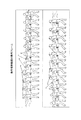
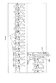
- motion transition image as shown in FIG. 34 is used for sports formation confirmation and the like.
- the motion transition image can easily recognize the motion transition by cutting out a person or an object (moving subject) at a certain characteristic time (key frame) and arranging them spatially. This is characterized in that even if the moving subject does not move spatially, an image moved spatially is intentionally generated. Generally, this is realized by drawing a picture, but it may also be realized by manually cutting out and arranging photographs.
- a key frame image to be processed is extracted from a plurality of frames of images obtained by video camera video or continuous shooting by a camera. Further, a method of cutting out the target subject portion in the key frame and arranging it is performed.
- the conventional motion transition image has a problem that it is difficult to achieve both expansion of the motion range and sufficient expression of the motion transition.
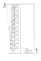
- FIG. 34 shows an example in which motion transition images are generated using key frames FK1 to FK20 extracted from moving image data obtained by capturing a person performing a golf swing with a video camera.
- the cutout width wa of one sheet when arranging the key frame images naturally has to be reduced.
- the moving range of the moving subject cannot be covered, and a part of the moving subject that should be the target is cut off.
- the golf club tip portion is missing. This is not visually desirable, and is not appropriate in consideration of uses such as form check.
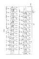
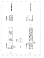
- FIG. 35 shows an example in which the cutout width from one key frame image is widened as shown as cutout width wb. In this case, the number of keyframe images that can be arranged as one image is reduced.
- FIG. 35 shows an operation transition image generated by extracting eight key frames FK1, FK4, FK7, FK10, FK11, FK14, FK17, and FK20 from the 20 key frames FK1 to FK20 of FIG. .
- the cutout width is widened so as to cover the entire motion range of the moving subject, the number of key frames existing in the final image to be generated is reduced and the expression of motion transition is lacking. Conversely, if the cutout width is narrowed, the number of key frames can be increased and the moving subject can be expressed finely in time, but the moving range of the moving subject cannot be covered, and a part of the moving subject that is supposed to be cut out. There is an inconvenience.
- Such a motion transition image is conventionally a still image that represents a motion transition by simply arranging a plurality of key frames and synthesizing the images. It is also desired to realize an operation transition image.
- Such a motion transition image is generated and recorded, it is preferable that the motion transition image is reproduced and confirmed in a manner that is easy for the user to understand and has good operability after imaging.
- the display control apparatus of the present invention is each composite image data generated by sequentially performing image composition processing for each input of frame image data, and the moving subject images of each frame image data are sequentially arranged in a predetermined direction.
- Each of the composite image data that can be displayed as a moving image is recorded from a recording medium on which a series of recording frame image data is recorded. Accordingly, the frame position to be reproduced is determined in the series of recording frame image data, the reproduction processing unit is caused to reproduce the recording frame image data at the determined frame position, and the reproduced recording frame image data is reproduced.
- a display control unit that performs display control.
- the display control unit moves forward or backward from the frame position of the recording frame image data currently being reproduced and output in accordance with a drag operation detected as the user instruction (for example, an operation of tracing the touch panel with a finger).
- the reproduction processing unit is caused to reproduce the recording frame image data at the frame position, and display control of the reproduced recording frame image data is performed.
- the display control unit An end frame position that is a front or rear frame position from the start frame position is determined, and each recording frame image data from the start frame position to the end frame position is sequentially reproduced by the reproduction processing unit, and the reproduced recording is performed. Control display of frame image data.
- the display control unit moves forward or backward from the frame position of the recording frame image data currently being reproduced and output in response to a flick operation detected as the user instruction (for example, an operation of flicking a finger on the touch panel).
- the reproduction processing unit is caused to reproduce the recording frame image data at the frame position, and display control of the reproduced recording frame image data is performed.
- the display control unit determines from the start frame position when the frame position of the recording frame image data currently being reproduced and output is set as the start frame position according to the flick operation speed and the flick operation direction detected as the user instruction.
- An end frame position that is a front or rear frame position is determined, and each recording frame image data from the start frame position to the end frame position is sequentially reproduced by the reproduction processing unit, and the reproduced recording frame image data Perform display control.
- the display control unit moves forward or backward from the frame position of the recording frame image data currently being reproduced and output in response to a point operation (for example, an operation of touching a certain position on the touch panel) detected as the user instruction.
- the reproduction processing unit is caused to reproduce the recording frame image data at the frame position, and display control of the reproduced recording frame image data is performed.
- the display control unit may move forward or backward from the start frame position when the frame position of the recording frame image data currently being reproduced and output is set as the start frame position according to the position of the point operation detected as the user instruction.
- the end frame position that is the frame position of the recording frame is determined, each recording frame image data from the start frame position to the end frame position is sequentially reproduced by the reproduction processing unit, and display control of the reproduced recording frame image data is performed. Do.
- the recording frame image data is read and displayed.
- the program of the present invention is a program that causes the arithmetic processing unit to execute the above steps.
- each composite image data generated by sequentially performing image composition processing for each input of frame image data, and moving subject images of each frame image data are sequentially arranged in a predetermined direction.
- Each composite image data that can be displayed as a moving image is recorded as a series of recording frame image data.
- Each composite image data is, for example, as follows. First, the original frame image data is one of each frame constituting a moving image, or, for example, one still image captured continuously. It is a picture. That is, the image data constituting one image is shown widely.
- processing for separating a moving subject layer and a background layer in the image is performed on the frame image data.
- the latest frame image data inputted is synthesized with the existing composite image data at that time.
- a large number of moving subject images can be arranged by reducing the width of one frame.
- the moving subject of the latest frame image data and the moving subject of the previous frame image data are used. Overlapping parts occur. Therefore, the moving subject layer of the latest input frame image data is given priority first, and the layer image composition processing is given with priority given to the moving subject layer of frame image data related to the previous image composition processing second.
- a composite image is generated in a state where a part of the moving subject overlaps the moving subject of the previous frame.
- the composite image data generated in this way is recorded on a recording medium as a series of recording frame image data.
- each composite image data (recorded frame image data) is reproduced and displayed as each frame of a moving image, thereby displaying a moving image that understands the composition process, a still image display at a certain stage of the composition process, and the like. Can be executed. Further, at this time, by responding to a drag operation, a flick operation, a point operation, etc., it is possible to easily present a scene to be viewed at each stage of the composition process to the user.
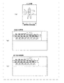
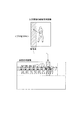
- a display control device is a display control device that controls display contents on a display screen, and has divided display regions that have a predetermined number of regions and are arranged in a predetermined order. In each divided display area of the display screen, images representing the same moving subject at different times obtained by continuously capturing the same moving subject are displayed simultaneously, and according to the time series of the same moving subject.
- the display content is controlled so that the images representing the same moving subject displayed in the respective divided display areas are arranged in order, and the display screen is displayed according to a user instruction or a moving image reproduction process.
- a display control method is a display control method for controlling the display content of a display screen.
- the display control method has a preset number of areas and has divided display areas arranged in a predetermined order.
- a program according to another aspect of the present invention is a program that causes an arithmetic processing unit to execute the above steps.
- the display content on the display screen is a display in which a large number of moving subjects are arranged so that images representing the same moving subject are simultaneously displayed. Then, the display content is controlled so that images representing the same moving subject displayed in the respective divided display areas are arranged in an order corresponding to the time series of the same moving subject. For example, images of the same moving subject as the same person or the like at each time point (for example, each state in the golf swing process) are displayed side by side in chronological order on the display.
- the display content includes an image representing the same moving subject at a time different from the display content displayed on the display screen in accordance with a user instruction or a moving image reproduction process
- the same motion at the different time is displayed.
- Display control is performed so that each image of the same moving subject including the subject is displayed in each of the divided display display areas in a state where the order according to the time series of the same moving subject is maintained.
- it is displayed in each of the divided display display areas while maintaining the order corresponding to the time series of each moving subject image.
- the present invention by reproducing the composite image data at each stage as the motion transition image, it is possible to dynamically display the composite process of the image, and at the stage that the user wants to see in the composite process.
- Reproduced images can be provided with an easy operation for the user.
- a more intuitive operation can be performed by associating the position on the time axis of the moving image with the position on the spatial axis by a touch panel or the like.
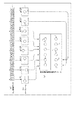
- FIG. 1 is a block diagram of an image processing apparatus according to an embodiment including a display control apparatus of the present invention. It is explanatory drawing of the production
- FIG. 1 shows a configuration example of an image processing apparatus 1 according to the embodiment.
- the image processing apparatus 1 is an apparatus that performs an image composition process as an operation transition image, and also includes an apparatus unit (display control unit) that records, reproduces, and displays an operation transition image as the image recording / playback unit 40. It is supposed to be.
- the configuration of the image processing apparatus 1 of this example includes an input image selection unit 2, a layer processing unit 3, an image output unit 4, a composite image update holding unit 5, an image input unit 10, a moving subject information generation unit 11, A moving subject information input unit 12 and an image recording / reproducing unit 40 are shown.
- these parts are not necessarily limited to the components in the same housing.
- the image input unit 10, the moving subject information generation unit 11, the moving subject information input unit 12, and the output device 40 can be considered as separate components. Further, only one of the moving subject information generation unit 11 and the moving subject information input unit 12 may be provided.
- the image recording / playback unit 40 is configured as a separate recording / playback / display device.
- Each of the input image selection unit 2, the layer processing unit 3, the image output unit 4, and the composite image update holding unit 5 may be configured as a hardware block. However, in an arithmetic processing device such as a microcomputer, software It can also be realized as a functional block realized by a program.
- the image processing apparatus 1 may be provided inside a device such as an imaging device (video camera or the like) or a video reproduction device, or may be configured as one image processing dedicated device. Furthermore, it may be configured to execute an image processing function realized by cooperation of software and hardware in a personal computer or the like.
- the image input unit 10 inputs a frame image data group that is a source of a motion transition image (still image or moving image) to be generated.
- the frame image data is one of each frame constituting a moving image or, for example, one image of each still image captured continuously. That is, the term “frame image data” is used to widely indicate the image data constituting one image.
- This image input unit 10 corresponds to a lens system, a light receiving element, and a series of imaging system parts for obtaining a captured image signal by performing image signal processing if the image processing apparatus 1 is mounted on the imaging apparatus. Become. If a captured image obtained by an external imaging device is captured, the image input unit 10 may be a reception processing system for image signals transferred / transmitted / downloaded from an external device.
- a tuner unit for broadcast waves an external device interface unit such as a USB (Universal Serial Bus) interface, a wired or wireless network communication unit, and the like are assumed.
- an image signal such as captured image data is recorded on a recording medium such as a memory card (solid memory) or an optical disk
- the image input unit 10 performs a reproduction system part for reproducing the recording medium or the like. Realized as a playback program.
- each frame image data as a moving image or a plurality of frame image data obtained by still image continuous shooting or the like is input, and the image input unit 10 inputs these frame image data into an input image selection unit. 2 and the moving subject information generation unit 11.
- the image input unit 10 may perform preprocessing. When a moving image file is received, it is expanded into each frame, and when an interlaced image is received, it is converted into a form necessary for processing such as progressive processing. Also, enlargement / reduction may be performed.
- the moving subject information generation unit 11 uses the original image group (frame image data group) and other external information (depth information, etc.) received from the image input unit 10 to generate moving subject information.
- the moving subject information is information that can determine which portion of the input frame image data is a moving subject and which portion is a background.
- the moving subject information generation unit 11 generates moving subject information corresponding to each input frame image data, and supplies it to the input image selection unit 2.
- the moving subject information may be expressed as a moving subject image. In this case, whether each pixel is a moving subject or a background is expressed as a pixel value. In addition, information indicating the location of each subject may be expressed by an equation or a vector.
- the moving subject information generation unit 11 separates each of the moving subjects when there are a plurality of moving subjects, and may separate them according to depth. In this case, when the moving subject information is represented by an image, it is not a binary image of the moving subject or the background, but a multi-value image (or multi-channel image) representing what depth each pixel is at.
- the moving subject information may not be generated in the image processing apparatus 1 of this example, and moving subject information generated by another device or program can be received.
- the moving subject information input unit 12 is shown as a part that receives moving subject information for each frame image data input by the image input unit 10 from the outside.
- the moving subject information input unit 12 inputs moving subject information corresponding to each input frame image data from the outside and supplies the input to the input image selection unit 2. Accordingly, at least one of the moving subject information generation unit 11 and the moving subject information input unit 12 may be provided.
- the moving subject information generated by the moving subject information generation unit 11 and the moving subject information input by the moving subject information input unit 12 can be used together. In this sense, the moving subject information generation unit 11 and the moving subject information are also included. It is also useful that both information input units 12 are provided.
- the input image selection unit 2 performs processing for generating a motion transition image for the frame image data sequentially supplied from the image input unit 10. That is, necessary image data used for the composition processing in the layer processing unit 3 is selected, and an appropriate combination of images is output to the layer processing unit 3. Further, the input image selection unit 2 outputs information necessary for the synthesis process such as moving subject information corresponding to the frame image data output to the layer processing unit 3 and coordinate information for synthesis to the layer processing unit 3.
- a key frame determination unit 21 and a coordinate calculation unit 22 are shown in the input image selection unit 2.
- the key frame determination unit 21 performs key frame determination processing and selection of frame image data to be output to the layer processing unit 3 based thereon.
- the coordinate calculation unit 22 performs coordinate calculation for the synthesis process.
- a key frame is a plurality of images with different time axes that are left in the same still image as a motion transition locus in a final output image (a final frame image in the case of a moving image) as a motion transition image.
- frames captured at appropriate intervals per unit time in a group of continuous frame image data are assumed to be key frames. There is no need, and the interval may be changed to a suitable interval for visually recognizing the movement of the imaging target.
- the key frame determination unit 21 performs a process of selecting frame image data to be a key frame from the frame image data sequentially supplied from the image input unit 10.
- the input all frame image data is used for the processing of the layer processing unit 3, and the handling of the composite image in the layer processing unit 3 differs depending on whether it is a key frame or not. Become.
- FIG. 2 shows a key frame.
- FIG. 2A schematically shows image data input to the input image selection unit 2. For example, it is moving image data, and F1, F2, F3,... In the figure indicate one frame image data.
- the input image selection unit 2 selects a key frame from temporally continuous frames as such a moving image. As an example, assuming that every fifth frame is a key frame, the frames F1, F6, F11, F16, F21,. In FIG. 2 (b), the image contents of each of these key frames are shown in graphics.
- frame image data (for example, F2, F3, etc.) other than the key frame is also used for the composition process.
- new frame image data is synthesized with the previous synthesized image data with the key frame left.
- FIG. 2 (c) shows an example of the final frame of the motion transition video, but by combining new frame image data with the composite image data with only the key frame left, In the frame, the image content is such that the images of the key frames are arranged at almost equal intervals. Details will be described later.
- the layer processing unit 3 includes a layer separation unit 31, a layer processing unit 32, and a layer composition unit 33, and performs a motion transition image generation process.
- the layer separation unit 31 performs layer separation of the input frame image data using the moving subject information.
- a layer refers to each frame image data separated by a moving subject portion and a background portion.
- the layer separation unit 31 generates an image of each layer by separating the corresponding range in which layer synthesis is performed, for example, based on moving subject information, an input image and a previous key frame image into a background and a moving subject. If there are a plurality of moving subjects and their depths are known, the layers are separated into the number of moving subjects + the number of backgrounds.
- FIG. 3A shows an input image (one piece of frame image data) and moving subject information about the frame image data.
- the input image selection unit 2 outputs the frame image data F1, F2, F3... Sequentially supplied from the image input unit 10 to the layer processing unit 3.
- the input image selection unit 2 is supplied with moving subject information corresponding to each frame image data from the moving subject information generation unit 11 or the moving subject information input unit 12.
- the input image selection unit 2 also supplies moving subject information corresponding to the frame image data to the layer processing unit 3.
- FIG. 3A shows the frame image data given to the layer processing unit 3 and its moving subject information as shown in the upper and lower parts of FIG.
- the moving subject information is expressed by binary values. That is, the information is “1” for a pixel that is a moving subject, “0” for a background pixel other than the moving subject, and the like.
- the white portion represents “1”, that is, a moving subject
- the black portion represents “0”, that is, a background.
- the layer separation unit 31 separates the input frame image data by using such moving subject information.
- FIG. 3B shows the moving subject layer and the background layer after separation.
- multivalued moving subject information of three or more values can be used.
- the moving subject information generation unit 11 or the moving subject information input unit 12 generates (or acquires) moving subject information having different values depending on the depths of the moving subjects (the front-rear relationship in the depth direction on the image). )
- the layer separation unit 31 can separate the layer into the number of moving subjects + the number of backgrounds.
- the layer processing unit 32 performs processing such as cutting, enlargement / reduction, and coordinate movement of each separated layer. In other words, various processes are performed on the separated layers to process them into a form that can be combined.
- the processing performed by the layer processing unit 32 is often performed with geometric operations such as “enlargement / reduction”, “rotation”, and “translation”. However, image processing such as enhancement of an operation part may be performed.
- the enlargement / reduction is determined by the number of key frames, the output image size, and the like.
- the layer processing unit 32 performs various processes on the separated layers and processes them into a form that can be combined.
- the motion transition image usually covers the entire area of the input frame image data. Instead, it is done by cutting out a part.
- the range in which the moving subject is effective is different from the background area left in the final image.
- the width and height of the image as the input frame image data are (Wimg, Himg)
- the width and height of the transition operation effective area are (Wmov, Hmov)
- the width and height of the remaining background area are (Wback, Hback).
- an area mode such as (a), (b), and (c) in FIG. 4 is assumed. Note that (a), (b), and (c) in FIG. 4 are examples, and the present invention is not limited to these.
- the transitional motion effective area shown in FIGS. 4A, 4B, and 4C is a range in which a main moving subject is cut out.
- the remaining background area is an area used as a background image in the synthesis process.
- transition motion effective region values (Wmov, Hmov) and residual background region values (Wback, Hback) are the transition direction of the subject, that is, the direction in which the image progresses in time when expressed as a motion transition image.
- the width and height are the same.
- the height (Hmov, Hback) is the original value as in the example of FIG.
- the width (Wmov, Wback) is set to the same value as the width (Wimg) of the original frame image data as in the example of FIG.
- FIG. 5 shows a setting example of the transition motion effective area and the remaining background area according to the example of FIG. 4B for the actual frame image data.
- FIG. 5A shows the original input frame image data.
- the size of the frame image data is VGA (640 ⁇ 480).
- an appropriate setting may be made according to the size and movement of the subject, and an image used for the composition process may be cut out.
- the layer composition unit 33 performs composition processing using the processed layer and the previous composite image. That is, the output image is combined based on the image processed by the layer processing unit 32, the previous combined image, moving subject information, and the like.
- the composition here refers to determining which layer of pixels to reflect in the output image based on the moving subject information and generating the output image. In some cases, the pixels are selected from the pixels of a single layer, but in some cases, the pixels of a plurality of layers are mixed and output.
- image synthesis processing is performed according to input of frame image data to generate synthesized image data.
- layer image composition processing is performed on a partial region of existing composite image data at the time when frame image data is input.
- the moving subject layer of the latest input frame image data is given priority first, and the moving subject layer of the frame image data related to the previous image composition processing is given priority second.
- the image output unit 4 outputs the synthesized image synthesized by the layer processing unit 3 to the image recording / reproducing unit 40.
- the image recording / reproducing unit 40 is shown as an example of a part that performs a recording operation, a reproducing operation, and a display operation on a recording medium.
- the image output unit 4 sequentially outputs the composite image data generated by the layer processing unit 3 every time frame image data is input, to the image recording / reproducing unit 40 as frame image data for recording to be recorded on the recording medium. Further, the image output unit 4 sequentially displays the combined image data generated by the layer processing unit 3 every time frame image data is input as an operation transition moving image on the display unit 45 in order to the image recording / reproducing unit 40. Output.
- the specific output destination of the composite image data by the image output unit 4 is a system configuration such as output to another display device, output to another recording device, network output, etc. It can be considered variously.
- the image output unit 4 uses the current synthesized image data as the existing previous synthesized image data during the next process.
- the image is updated and stored in the image update holding unit 5.
- the frame image data related to the current synthesis process is a non-key frame
- the current synthesized image data is not used as the previous previous synthesized image data in the next process, and therefore the synthesized image update holding unit 5 Is not output.
- the composite image update holding unit 5 holds the composite image data at each time point in the process of generating the motion transition image. For example, when generating a motion transition image, the composite image at each time point output from the image output unit 4 is updated and held. For example, the previous synthetic image data required in the synthesis process is updated and held as the previous time, the last time, or the like. Also, key frame information at the time of generating each composite image, moving subject information of the key frame, and the like are stored and held.
- the image recording / playback unit 40 includes a user interface control unit (UI control unit) 41, a recording / playback processing unit 42, a recording medium drive unit 43, a display driver 44, a display unit 45, and a touch panel 46.
- UI control unit user interface control unit
- the UI control unit 41 is formed by a microcomputer, for example.
- the UI control unit 41 controls each unit in the image recording / reproducing unit 40 to execute a recording operation or a display operation on the recording medium of the composite image data supplied from the image output unit 4. Also, a reproduction operation from the recording medium and a display operation of the reproduced composite image data are executed.
- Each frame image data as composite image data supplied from the image output unit 4 to the image recording / reproducing unit 40 and recorded on the recording medium is distinguished from the original frame image data input by the input image selection unit 2. In a sense, it is also referred to as “recording frame image data”.
- the recording / playback processing unit 42 Based on the control of the UI control unit 41, the recording / playback processing unit 42 performs processing for recording the recording frame image data, for example, compression processing, error correction code addition, encoding for recording data formation, and the like.
- the recording / playback processing unit 42 controls the recording medium driving unit 43 to execute recording driving for the recording medium.
- the recording / playback processing unit 42 performs playback processing of the recorded frame image data from the recording medium based on the control of the UI control unit 41. That is, the recording medium driving unit 43 is controlled to read data from the recording medium.
- the read recording frame image data is subjected to predetermined decoding processing, error correction processing, and the like to reproduce recording frame image data forming each frame of the moving image.
- the recording frame image data is supplied to the display driver 44 for display reproduction.
- the recording medium driving unit 43 is a part that performs recording / reproduction driving on the recording medium.
- various media such as an optical disk, a magnetic disk, a hologram disk, a memory card incorporating a solid memory, a hard disk, and a solid memory are assumed.
- the recording medium driving unit 43 is formed as a disk driving unit including an optical pickup, a spindle mechanism, a servo mechanism, and the like. That is, it may be a portion where information is written / read according to the recording medium employed.
- the display unit 45 is a display device such as a liquid crystal panel or an organic EL panel.
- the display driver 44 causes the display unit 45 to perform video display based on the control of the UI control unit 41.
- the display driver 44 performs a process of causing the display unit 45 to display the composite image data supplied from the image output unit 4 when the layer processing unit 3 executes the synthesis process. Further, when the reproduction is performed by the operations of the recording / reproduction processing unit 42 and the recording medium driving unit 43, the reproduced recording frame image data is displayed on the display unit 45.
- the touch panel 46 is formed on the screen of the display unit 45 and is used for user operations.
- the user can perform later-described operations (drag operation, flick operation, point operation, etc.) using the touch panel 46 according to the display contents on the display unit 45.
- Operation information (information such as a touch position by the user) by the touch panel 46 is supplied to the UI control unit 41.
- the UI control unit 41 causes the recording / playback processing unit 42 to execute a necessary playback operation according to operation information such as a touch position and the display content at that time.
- Example of motion transition image generation / recording process In such an image processing apparatus 1, an example of a motion transition image generation process executed mainly by the input image selection unit 2, the layer processing unit 3, the image output unit 4, and the composite image update holding unit 5 will be described.
- a case of generating a motion transition moving image as shown in FIGS. 6 to 15 will be described as an example, and specific processing examples will be described with reference to FIGS.
- a key frame is selected from the frame image data input as described above, but a frame other than the key frame is also used in the composition process.
- the existing combined image data as a target for combining new frame image data is an image in which only key frames are reflected.
- FIGS. 6 to 15 it is assumed that the key frame is selected as shown in FIG.
- FIG. 6 shows the composite image data when the first frame image data (for example, key frame) F1 is input.
- (K) is attached to the frame image data used as the key frame.
- FIG. 7 shows composite image data when the second frame image data F2 that is not a key frame (hereinafter, frame image data that is not a key frame is referred to as “non-key frame”) is input.
- the non-key frame F2 is synthesized in a pixel range shifted by a predetermined amount with respect to the key frame F1.
- the moving subject image of the latest frame is always given priority for the portion where the moving subject overlaps.
- a method of synthesizing the input frame image data with the existing synthesized image data is adopted.
- the existing composite image data at the time of synthesizing the non-key frame F2 is composite image data as shown in FIG.
- the composite image data when the third non-key frame F3 is input is shown in FIG.
- the non-key frame F3 is synthesized in a pixel range shifted by a predetermined amount with respect to the non-key frame F2 of FIG.
- the composition processing adopts a method of synthesizing the input frame image data with the existing composite image data as described above, but the composite image data when the non-key frame is input is the existing composite image. Not used as data. Therefore, even when this non-key frame F3 is input, the existing composite image data remains the composite image data of FIG.
- the previous non-key frame F2 is not used for composition, and the non-key frame F3 is synthesized with the existing composite image data at that time, so that the moving subjects of the frame image data F1, F3 are as shown in the figure.
- the image to be expressed is not used for composition, and the non-key frame F3 is synthesized with the existing composite image data at that time, so that the moving subjects of the frame image data F1, F3 are as shown in the figure. The image to be expressed.
- the composite image data of the key frame F1 + the non-key frame F4 is generated in the same manner, and when the fifth non-key frame F5 is input. Similarly, composite image data of key frame F1 + non-key frame F5 is generated. That is, in any case, the frame image data input to the existing combined image data at that time is combined.
- FIG. 9 shows composite image data when the second key frame F6 is input.
- the key frame F6 is combined with the existing composite image data (in this case, only the key frame F1).
- the composite image data of FIG. 9 is also stored as existing composite image data.
- the existing composite image data used for composition not only the composite image data at the time of the previous key frame input (previous composite image data), but also the composite image data at the time of the previous key frame input (previous composite image data) ) May be used.
- the previous synthesized image data and the previous synthesized image data are used, and therefore, the previous synthesized image data and the previous synthesized image data are used here.
- the existing combined image data is used for combining each pixel with priority when layer combining, but in that sense, it depends on the extent to which the overlapping portion of the moving subject falls.
- the use range of the composite image data going back to the past may be set.
- an example is also conceivable in which the combined image data, the combined image data, and the like are used for the combining process.
- the previous composite image data (the composite image shown in FIG. 9) and the previous composite image data (the composite image shown in FIG. 6) are updated and retained as existing composite image data. It is held in the unit 5 and used for subsequent synthesis processing.
- FIG. 11 shows composite image data when the non-key frame F8 is input. Also in this case, by synthesizing the image of the non-key frame F8 with the existing synthesized image data, a synthesized image is generated by the images of the key frames F1 and F6 and the image of the non-key frame F8 as shown in the figure. The same applies when non-key frames F9 and F10 are input thereafter.
- FIG. 12 shows the composite image data when the third key frame F11 is input.
- the key frame F6 is combined with the existing composite image data.
- the composite image data of FIG. 12 is also stored as existing composite image data.
- the previous composite image data is updated to the composite image of FIG. 12, and the previous composite image data is updated to the composite image of FIG.
- the input frame image data (key frame and non-key frame) are sequentially subjected to the synthesis process, and the composite image data as illustrated is obtained at each time point.
- these combined image data are output as one frame constituting each moving image.
- composite image data is generated every time frame image data is input, and moving image output proceeds as shown in FIGS. That is, the subject image of each frame including the non-key frame is synthesized while leaving the subject image of each key frame, and the synthesized image data is output at each time point.
- a moving image representing a motion transition such as a golf swing, that is, a motion transition moving image is output.
- FIG. 16 illustrates processing executed by the input image selection unit 2, the layer processing unit 3, the image output unit 4, and the composite image update holding unit 5 when generating a motion transition moving image.
- Steps F101 to F105 are processing of the input image selection unit 2.
- temporally continuous frame image data is supplied from the image input unit 10 to the input image selection unit 2.
- the input image selection unit 2 responds to the frame image data and the frame image data from the moving subject information generation unit 11 (or the moving subject information input unit 12) in step F102.
- a process for capturing moving subject information to be performed is performed.
- step F101 is a determination of whether a series of frame image data for generating a motion transition moving image has been taken, that is, whether the supply from the image input unit 10 has ended. In other words, the process proceeds from step F101 to F102 until the input of a predetermined number of frame image data to be reflected as the motion transition moving image is completed.
- the input image selection unit 2 selects whether or not the frame image data is used as a key frame in step F103. For example, when key frame selection is performed as shown in FIG. 2, frames every 5 frames, such as first, sixth, eleventh, and so on are set as key frames. As described above, the key frames are not necessarily set at equal intervals. For example, in the case of golf swing images as shown in FIGS. 6 to 15, a method of setting key frames at fine intervals before and after the moment of impact on the ball can be used.
- the input image selection unit 2 takes in the previous previous composite image data and the previous composite image data from the composite image update holding unit 5 at step F104. Note that there is no previous synthesized image data and no previous synthesized image data until the synthesis process is performed on the frame image data set as the first key frame. Further, there is no previous combined image data until the combining process is performed on the frame image data set as the second key frame. In step F104, if the previous combined image data and the previous combined image data are stored in the combined image update holding unit 5 at that time, the combined image data is captured.
- step F ⁇ b> 105 the input image selection unit 2 performs a pixel position coordinate calculation process for reflecting the current frame image data (key frame or non-key frame) in the composite image. That is, it is a calculation process of a pixel range to which the current frame image data is applied in the final synthesized image size (size of motion transition moving image).
- the input image selection unit 2 outputs the coordinates calculated in step F105, the current frame image data and moving subject information, the previous combined image data, and the previous combined image data to the layer processing unit 3.
- the layer processing unit 3 performs a process determination process in step F106.
- the process determination is a process for determining what kind of synthesis processing process is executed for each pixel (or for each column or each row) in a range where the synthesis processing is performed in order to perform efficient synthesis processing. is there. Note that, as shown in FIGS. 6 to 15, when the motion transition moving image in which the subject image transitions in the horizontal direction is generated, the process determination process may be performed for each pixel or each column. On the other hand, although not shown, when a motion transition moving image in which the subject image transitions in the vertical direction is generated, the process determination process may be performed for each pixel or for each row. The following description is based on an example in which process determination is performed for each column in accordance with the examples of FIGS.
- the process determination process performed in step F106 is shown in FIG.
- the current frame image data, the previous synthesized image data, and the previous synthesized image data are used for the synthesis process.
- the number of processes to be determined is six (processes P1 to P6). If the number of combined image data to be used increases, such as the combined image data, the number of processes increases.
- the previous key frame range information and moving subject information included in the previous composite image data, and the previous key frame range information and moving subject information included in the previous composite image data are used. These may be stored in the composite image update holding unit 5 in association with the previous composite image data and the previous composite image data, and read in step F102.
- each column for performing the process determination is each column in the range of A1 to A7. Within this range, process determination is performed with each pixel row (in the case of FIG. 13, the upper pixel row in the composite image data) as a target column.
- the layer processing unit 3 sets one column as a target column and acquires the pixel position (coordinate position in the composite image data).
- the range of the previous composite image data is the range from the A3 area to the A7 area in FIG.
- the layer processing unit 3 proceeds to step F203, and determines whether or not the column of attention is within the current transition operation effective region.
- the transition operation effective area this time is the transition operation effective area (see FIG. 5B) of the frame image data (key frame or non-key frame) input this time.
- the range of the area is the transition operation effective area (see FIG. 5B) of the frame image data (key frame or non-key frame) input this time.
- step F203 determines that the column of interest is not within the current transition operation effective region. If the layer processing unit 3 determines that the process P1 is applied to the column of interest. This is a case where the target column is in the A1 region of FIG. If the layer processing unit 3 determines in step F203 that the column of interest is in the current transition motion effective region, the layer processing unit 3 determines that the process P2 is applied to the column of interest. This is a case where the target column is in the area A2 in FIG.
- step F202 If it is determined in step F202 that the column of interest is within the range of the previous combined image data, the layer processing unit 3 proceeds to step F204 to determine whether or not the column of attention is in the current transition motion effective region. . If it is determined in step F204 that the column of interest is not within the current transition motion effective region, it is determined that the process P3 is applied to the column of interest. This is a case where the target column falls within the A6 and A7 regions of FIG.
- step F204 determines whether or not the target column is within the current transition motion effective region.
- the rear region is the rear side in the transition motion effective region with respect to the moving direction A of the motion transition image (when moving from left to right).
- (C) is a region not included in the remaining background region. In the case of an image in which the motion transition shifts from right to left, it is the right region in the transition motion effective region. In addition, in the case of an image in which the motion transition shifts from top to bottom, it is the upper region in the transition motion effective region.
- the column in the A5 area is determined to be in the rear area. If it is determined in step F205 that the target column corresponds to the rear region, the layer processing unit 3 determines that the process P4 is applied to the target column. This is a case where the target column is in the area A5 in FIG.
- step F205 determines whether or not the target column is within the range of the combined image data two times before.
- the range of the pre-synthesizing composite image data is the range from the A4 area to the A7 area in FIG.
- the layer processing unit 3 determines that the process P5 is applied to the column of interest. This is a case where the target column is in the area A3 in FIG.
- step F206 determines that the process P6 is applied to the column of interest. This is a case where the target column is in the area A6 in FIG.
- the layer processing unit 3 performs the synthesis process of step F107 each time the above-described process determination of FIG. 17 is performed for a certain target column in step F106 of FIG.
- Step F107 is a process of combining the pixels in the target column as a combined result image according to the process determination result, and layer separation, processing, and combining are performed as necessary. Steps F108 and F109 will be described later, but steps F106 to F109 are repeated until it is determined in step F110 that the current frame image data input this time has been processed. In other words, if the process determination process is performed in units of columns, the process determination is repeated until the process determination and the synthesis process are performed for all columns.
- FIG. 18 shows image data used for the composition processing.
- FIG. 18A shows a transition operation effective area of the input image (frame image data) input this time in step F102.
- (B) of FIG. 18 shows the previous combined image data existing at this time.
- (C) of FIG. 18 shows the pre-existing composite image data existing at this time. Note that these are examples of the input image, the previous combined image data, and the previous combined image data at the time of FIG.
- the process P1 is a process that does not perform drawing. Therefore, when it is determined that the column of interest is the process P1, in step F107, the combining process for reflecting the pixel in the combining result is not performed.
- the column to which the process P1 is applied is each column of the A1 area in FIG. 13, and therefore, nothing is drawn in the A1 area.
- the process P2 is a process of copying pixel data from the current frame image data transition operation effective area.
- the columns to which the process P2 is applied are the columns in the area A2 in FIG.
- This A2 area is an area that does not overlap with the previous combined image data (and the previous combined image data). Therefore, the pixels of the current input image may be reflected as they are.
- the pixels corresponding to the A2 area are pixels in each column indicated by the hatched portion in the input image transition operation effective area.
- the pixels in each column are copied as they are as the pixels in the area A2 in FIG.
- Process P3 is a process of copying pixel data from the previous combined image data.
- the columns to which the process P3 is applied are the columns of the A6 area and the A7 area in FIG.
- the A6 area and the A7 area are areas that do not overlap with the transition operation effective area of the frame image data input this time. Therefore, the pixels of the previous composite image data may be reflected as they are.
- the pixels corresponding to the A6 area and the A7 area are pixels in each column indicated by hatching in the previous synthesized image data.
- the pixels in each column of the previous synthesized image data are copied as they are as the pixels in the A6 area and A7 area in FIG.
- Process P4 is a process of copying pixel data of the moving subject image (moving subject layer) of the current frame image data onto the previous synthesized image data.
- the column to which the process P4 is applied is each column in the A5 area of FIG.
- This A5 area is the subsequent area of the frame image data input this time. In this area, only the moving subject of the current frame image data is displayed so as to overlap the previous synthesized image data.
- the upper part of FIG. 20 shows a moving subject image of the input image. This is a moving subject layer after the layer separation described with reference to FIG. 3 is performed on the input frame image data.
- the layer processing unit 3 performs layer separation using the moving subject information on the frame image data input this time by the function of the layer separation unit 31, and generates an image of only the moving subject shown (image without a background). .
- the shaded portion corresponds to the rear area.
- the pixels in each column corresponding to the subsequent region only the pixels constituting the moving subject image are transferred to the portion corresponding to the A5 region (hatched portion) of the previous synthesized image data shown in the lower part of FIG. In this way, the state in which the moving subject pixels in the rear area of the current frame image data are transferred onto the previous composite image data is reflected as the composite image data in the area A5 in FIG.
- the process P5 is a process of combining three layers of the moving subject image of the frame image data input this time, the moving subject image of the previous key frame, and the background image of the frame image data input this time.
- the columns to which the process P5 is applied are the columns in the A3 area in FIG. This A3 area is a part where the transition operation effective area of the frame image data input this time overlaps with the previous synthesized image data. Therefore, the three layers are synthesized in the priority order shown in FIG.
- FIG. 21A shows a moving subject image (moving subject layer) of the input image.
- FIG. 21C shows a background image (remaining background layer) of the input image.
- the layer processing unit 3 performs the layer separation described with reference to FIG.
- FIG. 21B shows a key frame when the previous combined image data is generated, that is, a moving subject image (moving subject layer) of the previous key frame.
- the previous key frame image is included in the previous composite image data, the moving subject image of the previous key frame can be extracted using moving subject information corresponding to the previous key frame.
- a portion corresponding to the region A3 on the image after synthesis in FIG. 13 is hatched.
- the moving subject image of the input image is given the first priority and the moving subject of the previous key frame as shown in FIG.
- Layer synthesis is performed with the image as the second priority and the background image of the input image as the third priority. That is, the highest priority is given to the pixels constituting the moving subject in the shaded area in FIG. In the portion other than the pixels constituting the moving subject in the shaded portion in FIG. 21A, if there is a pixel constituting the moving subject in the shaded portion in FIG. 21B, that pixel is applied. Pixels constituting the background image in FIG. 21C are applied to the other pixel portions. The state in which the pixels of the three layers are combined in this way is reflected as the combined image data of the area A3 in FIG.
- the process P6 includes four layers of the moving subject image of the frame image data input this time, the moving subject image of the previous key frame, the moving subject image of the previous combined image data, and the background image of the frame image data input this time. Is a process to synthesize.
- the column to which the process P6 is applied is each column in the A4 area of FIG.
- the A4 region is a portion where the transition operation effective region of the frame image data input this time overlaps with the previous combined image data and the previous combined image data. Therefore, the four layers are synthesized in the priority order shown in FIG.
- FIG. 22A shows a moving subject image (moving subject layer) of the input image.
- FIG. 22D shows a background image (remaining background layer) of the input image.
- FIG. 22B shows a key frame when the previous combined image data is generated, that is, a moving subject image (moving subject layer) of the previous key frame.
- FIG. 22C shows a key frame when the synthesized image data is generated two times before, that is, a moving subject image (moving subject layer) of the key frame two times before.
- the layer processing unit 3 performs the layer separation described with reference to FIG. 3 on the input frame image data by the function of the layer separation unit 31, and obtains these moving subject images and background images. Also, the moving subject image of the previous key frame and the moving subject image of the previous key frame are extracted from the previous synthesized image data and the previous synthesized image data using the moving subject information. In (a), (b), (c), and (d) of FIG.
- a portion corresponding to the area A4 on the image after synthesis in FIG. 13 is hatched.
- the moving subject image of the input image is given the first priority and the previous key frame for the pixels in the shaded row of (a), (b), (c), and (d) in FIG. Layered with the second priority for the moving subject image, the third priority for the moving subject image of the previous key frame, and the fourth priority for the background image of the input image. That is, the highest priority is given to the pixels constituting the moving subject in the shaded area in FIG. In the portion other than the pixels constituting the moving subject in the shaded portion of FIG. 22A, if there is a pixel constituting the moving subject in the shaded portion of FIG.
- step F107 in FIG. 16 one of the above processes P1 to P6 is executed as the processing of the target column in accordance with the process determination result in step F106. Note that the processing in steps F106 to F109 may be repeated not for each column but for each pixel. Then, when any of the processes is performed on all columns (all pixels) to be combined, for example, combined image data as shown in FIG. 13 is completed. At that time, the process of FIG. 16 proceeds from Step F110 to F111.
- step F ⁇ b> 111 the layer processing unit 3 supplies the composite image data to the image output unit 4.
- the image output unit 4 outputs the supplied composite image data to the image recording / reproducing unit 40 as one frame constituting the motion transition moving image.
- the image output unit 4 combines one image according to the time required for the synthesis process, the input interval of the frame image data from the image input unit 10, or the like to express a moving image that moves slowly.
- the image data may be continuously output as a plurality of frames constituting the motion transition moving image.
- step F112 the process branches depending on whether or not the frame image data processed this time is a key frame. That is, the process branches depending on the determination result in step F103. If the frame image data input this time is a key frame, in step F113, the combined image data generated this time is stored in the combined image update holding unit 5 in order to be used as the previous combined image data in the subsequent processing. Process to save.
- the composite image update holding unit 5 uses the previous composite image data held at that time as the previous composite image data, and newly holds the composite image data supplied from the current image output unit 4 as the previous composite image data.
- the moving subject information of the key frame is also stored along with the information.
- step F101 the process returns to step F101 to proceed to the next frame image data processing.
- an operation transition moving image as shown in FIGS. 6 to 15 is output. That is, the image recording / reproducing unit 40 performs recording processing and display processing by outputting the composite image data by the image output unit 4 in step F111.
- frame image data is input, and each time image synthesis is performed, the synthesized image data is output to the display driver 44 of the image recording / reproducing unit 40 as one frame constituting a moving image in step F111.
- the display driver 44 displays the composite image data on the display unit 45 as one frame of the moving image.
- an operation transition moving image as shown in FIGS. 6 to 15 is displayed and output on the display unit 45. That is, the process of the synthesis process is displayed as it is.
- each composite image data is recorded by the output in step F111. That is, the composite image data from the image output unit 4 is supplied to the recording / playback processing unit 42 as recording frame image data.
- the recording / playback processing unit 42 processes each recording frame image data as each frame constituting the motion transition moving image, controls the operation of the recording medium driving unit 43, and records it on the recording medium as a series of moving image data. To go.
- FIG. 23A schematically shows original frame image data F1, F2,... Input to the input image selection unit 2.
- FIG. 23A schematically shows original frame image data F1, F2,... Input to the input image selection unit 2.
- FIG. 23 In the process described above, when the frames F1, F2, F3. Generated.
- Each composite image data in (b) of FIG. 23 is, for example, one frame of image data as shown in FIGS.
- the composite image data is recorded on the recording medium as recording frame image data rF1, rF2, rF3. Therefore, each frame forming a series of moving images as motion transition moving images is stored. As can be seen from FIG. 23B, not only the composite image data at the time of key frame synthesis but also the composite image data at the time of non-key frame synthesis is recorded as one of the recorded frame image data.
- step F101 If it is determined in step F101 that all frames have been captured, the process proceeds to step F114, the composition process is terminated, and the image output unit 4 terminates the output of the composite image data.
- the display unit 45 may continuously output the composite image data of the final frame as shown in FIG. 15, for example. That is, on the display unit 14, the motion transition moving image of FIGS. 6 to 15 is completed and the last image of FIG. 15 is continued. At this time, all the composite image data up to that point is recorded on the recording medium as recording frame image data.
- each moving subject image is accurately represented without, for example, lacking the tip of a golf club, and a large number of moving subject images can be arranged, and the movement transition can be expressed at fine intervals. This makes it possible to easily and very easily confirm the formation of one's own sports, complex movements of wild animals, and natural phenomena in the laboratory. Moreover, since manual work such as cutting and pasting of image data is not required, the burden on the user is very light and useful.
- a motion transition video can be generated and displayed.
- this motion transition moving image has a high visual effect by outputting the composite image data at each time point as a moving image, and the motion transition can be easily understood.
- by recording the composite image data at each time point on the recording medium as the recording frame image data for the motion transition video it is possible to dynamically display the image composition process by playback at a later time. Therefore, the relevance of each synthesized video is easily communicated to the user.
- a drag operation, a flick operation, and a point operation which will be described later, it is possible to reproduce an operation transition moving image and an image at each operation stage with an operation intuitively understandable to the user.
- efficient processing is realized by performing the synthesis processing based on the process determination.
- the composition processing in the processes P5 and P6 involving the composition of layers of three layers and four layers is a processing with a relatively large processing load, but these are executed only in the necessary pixel region.
- An area that does not require layer composition can be handled by simple copy processing such as processes P1, P2, and P3. As a result, the processing efficiency can be improved and the processing load can be reduced.
- the copy process in step F109 is a process of copying the last moving subject in the upper stage as the first moving subject in the lower stage, for example, at the time shown in FIG.
- a predetermined range at the upper right end of the composite image data (when shifting from left to right) is set as the lower copy range.
- the layer processing unit 3 performs process determination, and for each column combined with the composite image data, in step F108, whether the column (or pixel) corresponds to the lower copy range (that is, the uppermost last region). Determine whether or not. If it falls under the lower copy range, in step F109, the pixels in that column are copied to the corresponding position in the lower row.
- the moving subject in the lower copy range can be accurately expressed without being partly interrupted. That is, depending on the state of the subject, the position of the last image in the upper stage may be interrupted, but such a subject is also appropriately displayed in the lower stage. As a result, the upper-stage operation transition and the lower-stage operation transition transition easily.
- steps F108 and F109 are necessary only when the operation transition images are displayed in a plurality of stages on the screen as in the examples of FIGS.
- a composition process in which all of the images are arranged in the horizontal direction (not to have two or more levels).
- the image processing apparatus 1 of the present embodiment may be any apparatus that can acquire a plurality of frame image data captured by an imaging apparatus that can capture a continuous still image or a moving image.
- an imaging apparatus that can capture a continuous still image or a moving image.
- it may be built in the imaging device, or may be built in a playback device that plays back a plurality of captured frame image data. Further, it may be incorporated in a device that receives / transfers input a plurality of captured frame image data. Therefore, the present invention can be widely applied to, for example, a mobile phone, a PDA (Personal Digital Assistant), a personal computer, a video playback device, a video editing device, and the like.
- PDA Personal Digital Assistant
- the UI control unit 41 instructs the recording / reproduction processing unit 42 to perform the reproduction process.
- the recording / playback processing unit 42 causes the recording medium drive unit 43 to read the recording frame image data rF1, rF2,... Recorded in the recording medium as shown in FIG. This is supplied to the driver 44.
- the display driver 44 sequentially displays the supplied recording frame image data rF1, rF2,... On the display unit 45.
- an operation transition moving image as shown in FIGS. 6 to 15 is displayed on the display unit 45.
- the user can view not only a still image as an operation transition image as shown in FIG. 15 but also an image such as a swing form as an animation in FIGS. 6 to 15 at an arbitrary time.
- the UI control unit 41 reproduces a series of recording frame image data rF1, rF2,.
- Data rF (z) is continuously displayed and output.
- the recording frame image data rF (z) of the final frame as shown in FIG. 15 is an image in which only key frames are arranged at almost equal intervals. For the user, there may be a case where it is desired to review between the key frames (that is, non-key frame images).
- the user can easily view an image at a desired stage by an operation using the touch panel 46.
- an example of a drag operation will be described as the operation method.
- FIG. 24 shows a state in which the recording frame image data rF93 of the final frame is displayed.
- the recording frame image data rF93 is synthesized image data obtained by synthesizing key frames F1, F6, F11,... F93 as original frame image data as shown in the figure.
- the composite image data is recorded on the recording medium as recording frame image data rF93.
- FIG. 24 shows a state in which, for example, the user reproduces the motion transition moving image, and after the moving image reproduction is completed, the recording frame image data rF93, which is the final frame, is continuously displayed and output.
- an area AN indicated by a broken line frame is an area of the latest frame image data F93 being displayed.
- the “latest frame image data” in this case refers to frame image data that is the most backward on the time axis among the original frame image data before composition on the display.
- the reproduced image displayed to the last is the recording frame image data rF93 which is the composite image data, but the area AN of the “latest frame image data” refers to the moving subject or background from the original frame image data F93.
- the latest frame image data area AN may be the range of the transition operation effective area (A2 to A5) of the current frame in the case of FIG. 13, for example. Alternatively, it may be set as a range of areas A3 and A4 where the moving subject is mainly located.
- the touch panel 46 As an operation on the touch panel 46, it is assumed that the user performs a drag operation drk that traces the left side of the display screen with a finger on the display screen as shown in the figure. Then, as shown in FIG. 25, the reproduced image changes according to the drag operation drk. That is, a reproduced image corresponding to the end position of the drag operation is output.
- the end position of the drag operation is a position corresponding to the original frame image data F58
- the combined image data (recorded frame image data rF58) at the time of synthesis of the original frame image data F58 is reproduced. Is done.
- each frame is reproduced in the opposite direction on the time axis in the recording frame image data rF92 ⁇ rF91 ⁇ rF90 ⁇ .
- a so-called reverse playback screen is executed in accordance with the movement of the finger pressing position. Then, if the position where the user ends the drag operation is, for example, a position corresponding to the recording frame image data rF58, the reverse reproduction ends in the state of FIG. 25, and the output of the recording frame image data rF58 of FIG. 25 is continued. Is done. That is, the display is in a still image state.
- the user performs a drag operation on the display of FIG. 25 from the latest frame image data area in the display state.
- the area of the original frame image data F58 becomes the area AN of the latest frame image data. It is assumed that a finger is placed in this area AN and a drag operation drk is performed slightly to the right. If the end position of the drag operation is a position corresponding to the original frame image data F59, as shown in FIG. 27, the recording frame image data rF59, which is the combined image data when the original frame image data F59 is input, is obtained. Played. That is, playback is performed by moving one frame of the moving image in the normal direction.
- the user can easily reproduce an image at a desired stage in the motion transition image by a drag operation. That is, during the drag operation, it is possible to see the moving image reproduction in the forward direction or the reverse direction according to the speed of tracing with the finger, and when the drag operation is finished, the still image corresponding to the end position can be seen.
- the original frame image data F58 and F59 in the above example are non-key frames. As described with reference to FIG. 23, not only the composite image data at the time of inputting a key frame but also the composite image data at the time of inputting a non-key frame is recorded as recording frame image data constituting a series of moving images without distinction.
- the display changes corresponding to the drag operation are summarized in FIG.
- FIG. 28A when the user performs a drag operation drk in the right direction from within the area AN of the latest frame image data on the display, a frame corresponding to the end position of the drag operation is obtained as an operation result. Up to is displayed. On the screen, the image of the moving subject is visually recognized as an image developed. As shown in (b) of FIG. 28, when the user performs a drag operation drk in the left direction from within the area AN of the latest frame image data on the display, a frame corresponding to the end position of the drag operation is obtained as an operation result. Up to is displayed reverse playback. On the screen, the image of the moving subject is visually recognized as a folded image.
- FIG. 28 shows a case where the user performs a drag operation drk in a portion other than the area AN of the latest frame image data in the display.
- the drag operation is invalidated and the reproduced image on the display is not changed.
- a processing example in which each recorded frame image data is reproduced up to the end position of the drag operation is also conceivable.
- the process described below is a process in which the UI control unit 41 controls the recording / playback processing unit 42 and the like according to the input of the touch panel 46.
- the UI control unit 41 causes the recording frame image data to be reproduced from the frame position of the recording frame image data currently being reproduced and output to the front or rear frame position.
- the correspondence between the position on the display (position on the touch panel) and the frame position is grasped as follows.
- the description is made on the assumption that the motion transition moving images are arranged in the horizontal direction in one row on the screen as shown in FIG. 28, not on the two rows on the screen as shown in FIG.
- the x coordinate is considered as the horizontal coordinate on the screen of the display unit 45 (on the touch panel 46).
- the recording frame image data to be reproduced can be determined according to the movement amount of the drag operation.
- the recording frame image data to be reproduced corresponding to the position of the original frame image data “F1” is “rF1”.
- the recording frame image data to be reproduced corresponding to the position of the original frame image data “F2” is “rF2”.
- the above function is considered as follows.
- the obtained frame number “4” is the frame number of the original frame image data F4, and this indicates the recorded frame image data rF4 as the frame number to be reproduced.
- the function processing may be performed using the y coordinate in the vertical direction, but if the x coordinate advances as the continuation of the upper stage in the lower stage, the above is performed.
- the function can be applied as it is.
- the upper stage is a case where the x coordinates of 0 to n are set, and the lower stage x coordinates are n + 1 to m, and the x coordinates of 0 to m are set.
- the y-coordinate on the touch panel 46 may be used simply by determining whether it is the upper level or the lower level.
- FIG. 29 shows a processing example of the UI control unit 41 as the drag operation handling processing. If an operation with the touch panel 46 is detected while reproducing certain recording frame image data rFm, the UI control unit 41 first acquires an x coordinate value x1 as a drag start position in step F401. That is, the x-coordinate value is detected using the position where the user first touched the touch panel 46 as the drag start position.
- step F402 the UI control unit 41 determines whether or not the drag start position x1 is within the area AN of the latest frame image data in the display content at that time. As shown in FIG. 28C, if the drag start position x1 is not within the range of the area AN, the current drag operation is invalid. In this case, the drag operation corresponding process from step F402 to FIG. Finish. On the other hand, if the drag start position x1 is within the area AN, steps F403 to F405 are performed.
- step F403 the UI control unit 41 acquires the elapsed position x2 of the drag operation. That is, it is the x coordinate value of the touch position at this time point as the touch panel pressing position moved by moving the finger from the drag start position x1.
- step F405 the UI control unit 41 controls the recording / playback processing unit 42 and the display driver 44 to execute frame drawing. That is, the recording frame image data rFm being displayed at the start of dragging to the recording frame image data rFn of the frame number n is reproduced.
- the recording / playback processing unit 42 performs processing for reading the recording frame image data from the recording medium in the order of recording frame image data rFm ⁇ rF (m + 1) ⁇ rF (m + 2). And supply to the display driver 44.
- the display driver 44 causes the display unit 45 to sequentially display the supplied recording frame image data rFm to rFN. As a result, the display as shown in FIG.
- the recording / playback processing unit 42 records the recording frame image data from the recording medium in the order of recording frame image data rFm ⁇ rF (m ⁇ 1) ⁇ rF (m ⁇ 2).
- a read process is performed and supplied to the display driver 44.
- the display driver 44 causes the display unit 45 to sequentially display the supplied recording frame image data rFm to rFN. As a result, the display as shown in FIG. 28B is executed.
- step F406 the UI control unit 41 determines whether or not the user has lifted his / her finger, that is, whether or not the drag operation has ended. If the drag operation has been completed, the process ends. In this case, the UI control unit 41 instructs the recording / playback processing unit 42 and the display driver 44 to continuously output the frame image data rFn at the end of dragging. On the other hand, if the drag operation continues, the value of x2 is substituted for x1 in step F407. That is, the elapsed position x2 at that time is regarded as the drag start position x1 in the next unit time. Then, the process returns to step F403 again and the same processes of steps F403 to F405 are performed. Therefore, playback is performed in accordance with the continued drag operation.
- an image as shown in FIGS. 28A and 28B is developed according to the continuous finger movement as the user's drag operation. Or it will be folded. That is, the UI control unit 41 detects the drag operation amount and the drag operation direction detected by the touch panel 41 every unit time. Then, when the frame position of the recording frame image data currently being reproduced and output is set as the start frame position, an end frame position that is a front or rear frame position from the start frame position is determined. Then, each recording frame image data from the start frame position to the end frame position is sequentially reproduced.
- the composite image data at each stage as the motion transition image by such a drag corresponding process, it is possible to dynamically display the composite process of the image and the stage that the user wants to see in the composite process.
- the reproduced image can be provided with an easy operation for the user.
- a more intuitive operation can be performed by associating the position on the time axis of the moving image with the position on the spatial axis by the touch panel.
- step F402 in FIG. 29 may be eliminated, and the above reproduction process may be performed according to the amount and direction of the drag operation without invalidating the drag operation outside the area AN.
- the drag start position x1 can be considered as the position of the area AN at that time.
- the flick operation is an operation in which the user flicks the touch panel 46 with a finger.
- FIG. 30 shows a playback mode corresponding to the flick operation.
- the user performs a flick operation to the right from within the area AN of the latest frame image data on the display as shown in FIG.
- the area AN is flicked with a finger in the right direction as shown in FIG.
- the image of the moving subject is visually recognized as an image developed.
- FIG. 30 (c) when the user performs a flick operation to the left from within the area AN of the latest frame image data on the display, reverse playback is performed up to a predetermined frame according to the flick operation. Is displayed.
- the image of the moving subject is visually recognized as a folded image.
- the UI control unit 41 reproduces the recording frame image data that becomes the front or rear frame position from the frame position of the recording frame image data currently being reproduced and output in accordance with the flick operation detected by the touch panel 46. Control to execute.
- An example of the flick operation handling process by the UI control unit 41 is shown in FIG.
- the UI control unit 41 acquires an x coordinate value x1 as a flick operation position in step F501. That is, the position where the user first touched the touch panel 46 is set as the flick operation position, and the x coordinate value is detected.
- step F502 the UI control unit 41 determines whether or not the flick operation position x1 is within the area AN of the latest frame image data in the display content at that time. If the flick operation position x1 is not within the range of the area AN, it is determined that the current flick operation is invalid, and the processing corresponding to the flick operation in FIG. On the other hand, if the flick operation position x1 is within the area AN, the process proceeds to step F503.
- the UI control unit 41 acquires the flick operation speed vd.
- the flick speed Vd is calculated from the minute change amount of the x coordinate of the pressed position in a certain unit time during the flick operation. If the flick direction is the right direction (in the case of FIG. 30A), the flick speed Vd is set to a positive value. If the flick direction is leftward (in the case of the example shown in FIG. 30C), the flick speed Vd is set to a negative value.
- the UI control unit 41 calculates a displacement distance ⁇ x according to the flick speed Vd.
- the displacement distance ⁇ x here corresponds to the number of frames to be reproduced.
- the number of frames is associated with the absolute value of the flick speed Vd.
- a linear function or a nonlinear function is set so that the displacement distance ⁇ x corresponding to the number of frames increases as the flick speed increases. That is, when the user quickly flicks with a finger, a large number of frames are reproduced, and when the user slowly flicks with a finger, a small number of frames are reproduced.
- the value of the displacement distance ⁇ x is a positive value and a large value.
- the value of the displacement distance ⁇ x When it is slowly flipped in the right direction, the value of the displacement distance ⁇ x is a positive value and a small value. When it is quickly flipped to the left, the value of the displacement distance ⁇ x is a negative value with a large absolute value. When slowly flipping leftward, the displacement distance ⁇ x is a negative value with a small absolute value.
- the UI control unit 41 controls the recording / playback processing unit 42 and the display driver 44 to execute frame drawing. That is, playback is performed from a certain recording frame image data rFm currently displayed to the recording frame image data rFn of the frame number n.
- the recording / playback processing unit 42 performs processing for reading the recording frame image data from the recording medium in the order of recording frame image data rFm ⁇ rF (m + 1) ⁇ rF (m + 2).
- the display driver 44 causes the display unit 45 to sequentially display the supplied recording frame image data rFm to rFN. As a result, the display as shown in FIG.
- the recording / playback processing unit 42 records the recording frame image data from the recording medium in the order of recording frame image data rFm ⁇ rF (m ⁇ 1) ⁇ rF (m ⁇ 2).
- a read process is performed and supplied to the display driver 44.
- the display driver 44 causes the display unit 45 to sequentially display the supplied recording frame image data rFm to rFN. As a result, the display as shown in FIG. 30C is executed.
- the UI control unit 41 finishes the process according to one flick operation. Thereafter, the UI control unit 41 instructs the recording / playback processing unit 42 and the display driver 44 to continuously output the frame image data rFn at the end of playback according to the flick operation.
- the images as shown in FIGS. 30A and 30C are expanded or folded according to the user's flick operation. That is, the UI control unit 41 moves forward from the start frame position according to the flick operation speed and the flick operation direction detected by the touch panel 41 when the frame position of the recording frame image data currently being output is set as the start frame position. Alternatively, the end frame position that is the rear frame position is determined. Then, each recording frame image data from the start frame position to the end frame position is sequentially reproduced.
- step F502 in FIG. 31 may be omitted, and the above reproduction process may be performed according to the flick operation speed and direction without invalidating the flick operation outside the area AN.
- the drag start position x1 can be considered as the position of the area AN at that time.
- a process of always using a constant displacement distance ⁇ x regardless of the flick speed can be considered. For example, in one flick operation, 10 frame playback always proceeds.
- Point operation> Next, a point operation will be described as still another operation example.
- the point operation is an operation in which the user touches and designates a certain position on the touch panel 46.
- FIG. 32 shows a playback mode corresponding to the point operation.
- the user touches a certain position on the display as shown in FIG. For example, it is a position where nothing is displayed as the display content at that time.
- a predetermined frame is reproduced and displayed according to the point operation.
- the image of the moving subject is visually recognized as an image developed.
- FIG. 32B when the user performs a point operation on the position of certain frame image data on the display, up to a predetermined frame is reversely reproduced and displayed according to the point operation.
- the image of the moving subject is visually recognized as a folded image.
- the UI control unit 41 reproduces the recording frame image data that becomes the front or rear frame position from the frame position of the recording frame image data currently being reproduced and output in accordance with the point operation detected by the touch panel 46. Control to execute.
- An example of the point operation handling process by the UI control unit 41 is shown in FIG.
- the UI control unit 41 acquires an x coordinate value xp as a point operation position in step F601. That is, the x coordinate value of the position where the user touches the touch panel 46 is detected.
- the recording frame image data rFn of the frame number n is a frame to be reproduced in accordance with the current point operation.
- the UI control unit 41 controls the recording / playback processing unit 42 and the display driver 44 to execute frame drawing. That is, playback is performed from a certain recording frame image data rFm currently displayed to the recording frame image data rFn of the frame number n.
- the recording / playback processing unit 42 performs processing for reading the recording frame image data from the recording medium in the order of recording frame image data rFm ⁇ rF (m + 1) ⁇ rF (m + 2). And supply to the display driver 44.
- the display driver 44 causes the display unit 45 to sequentially display the supplied recording frame image data rFm to rFN. As a result, the display as shown in FIG.
- the recording / playback processing unit 42 records the recording frame image data from the recording medium in the order of recording frame image data rFm ⁇ rF (m ⁇ 1) ⁇ rF (m ⁇ 2).
- a read process is performed and supplied to the display driver 44.
- the display driver 44 causes the display unit 45 to sequentially display the supplied recording frame image data rFm to rFN. As a result, the display as shown in FIG. 32B is executed.
- the UI control unit 41 ends the process according to one point operation.
- the UI control unit 41 thereafter instructs the recording / playback processing unit 42 and the display driver 44 to continuously output the frame image data rFn at the end of playback according to the point operation.
- an image as shown in FIGS. 32A and 32B is expanded or folded according to the user's point operation. That is, the UI control unit 41 determines whether the frame position of the recording frame image data currently being reproduced and output is the start frame position according to the point operation position xp detected by the touch panel 41. The end frame position to be the frame position is determined. Then, each recording frame image data from the start frame position to the end frame position is sequentially reproduced.
- the point operation position xp is an x coordinate value behind the current position of the latest frame image data AN, that is, an area having no image display as shown in FIG. Do.
- the point operation position xp is the x coordinate value ahead of the current latest frame image data AN, that is, the position corresponding to the frame image data of the young number as shown in FIG.
- Reverse playback is performed for a predetermined number of frames. That is, this is an example of processing in which only forward / rearward is designated and the number of playback frames is constant.
- ⁇ 3-4 Other operation examples> As described above, examples of the drag operation, the flick operation, and the point operation are given, but various other operation examples are conceivable.
- a drag and drop operation the position where the finger is released is set as the drop position. Then, at the time of dropping, it can be considered that the corresponding recording frame image data from the drag start position to the drop position is reproduced as a moving image.
- the operation is performed using the touch panel 46.
- the operation can be performed using an operation input device other than the touch panel.
- an operation input device other than the touch panel.
- a drag operation, a flick operation, and a point operation are performed using a mouse.
- operation using a remote controller is also conceivable.
- a remote controller provided with a click button, an angular velocity sensor, an acceleration sensor, or the like is used, it is easy to perform a drag operation, a flick operation, or a point operation such as moving a pointer on the screen.
- a detection unit capable of detecting the coordinates of the light input position is provided on the screen, and the operation can be performed with a laser pointer or the like that shines light on the screen.
- the image recording / playback unit 40 or the UI control unit 41 can be regarded as a display control device having the following configurations (A), (B), and (C).
- A Different times obtained by continuously imaging the same moving subject in each divided display area of a display screen having a predetermined number of areas and having divided display areas arranged in a predetermined order.
- the display control device controls the display content of the display screen so that images representing the same moving subject are simultaneously displayed.
- the display content is controlled so that images representing the same moving subject displayed in the respective divided display areas are arranged in an order corresponding to the time series of the same moving subject.
- each divided display area of the display screen having a predetermined number of areas and having divided display areas arranged in a predetermined order corresponds to a display area of each frame image data as shown in FIG. 24, for example. It is an area to do.
- the display content on the display screen is, for example, FIG. 24 to FIG. 24 so that images representing the same moving subject at different times obtained by continuously capturing the same moving subject are displayed simultaneously in each of the divided display areas.
- images of the same moving subject as the same person or the like at each time point are displayed in time series on the display.
- the display content includes an image representing the same moving subject at a time different from the display content displayed on the display screen in accordance with a user instruction or a moving image reproduction process
- flick This corresponds to an operation or a point operation.
- the moving image reproduction process is not limited to a user instruction, and refers to various cases where a moving image or a pseudo moving image is reproduced. In such a case, each image of the same moving subject including the same moving subject at different times maintains the order corresponding to the time series of the same moving subject in the divided display display area. Display control so that each is displayed.
- the object to be displayed is the above-described composite image data. It is not limited to recording frame image data. In other words, it can be applied to the case where images of the same moving subject arranged in time series are divided on the screen and displayed in time series regardless of the source image.
- the display control apparatus of the present invention can be applied to various devices that perform image display processing in addition to a dedicated apparatus that reproduces and displays motion transition images.
- an imaging device, a home or business image recording / playback device, a game machine, a video editing machine, and the like are assumed.
- the display control apparatus is realized in a general-purpose personal computer or other information processing apparatus.
- a program for causing the arithmetic processing unit to execute processing corresponding to various operations as shown in FIGS. 29, 31, and 33 as image display processing application software appropriate image display processing can be performed on a personal computer or the like. realizable.
- the program that realizes the display process of the image processing apparatus 1 is a program that causes the arithmetic processing apparatus to execute the following steps. That is, there is a moving image display in which each synthesized image data generated by sequentially performing an image synthesis process for each input of frame image data, in which moving subject images of each frame image data are sequentially arranged in a predetermined direction. Each composite image data that can be executed is targeted for a recording medium recorded as a series of recording frame image data. Then, when a certain recording frame image data is read and reproduced and displayed, a step of detecting a user instruction for the reproduction display and the series of recording frame image data in accordance with the detected user instruction. The frame position to be reproduced is determined, the recording frame image data at the determined frame position is controlled to be reproduced, and the display control of the reproduced recording frame image data is performed.
- the program that realizes the display control process of the UI control unit 41 is a program that causes the arithmetic processing unit to execute the following process. That is, different times obtained by continuously imaging the same moving subject in each divided display area of a display screen having a predetermined number of areas and having divided display areas arranged in a predetermined order.
- the same moving subject at the different time Display control is executed so that each image of the same moving subject including the image is displayed in each of the divided display display areas in a state in which the order according to the time series of the same moving subject is maintained.
- the present invention can be easily realized in various information processing apparatuses using personal computers, mobile phones, PDAs (Personal Digital Assistants), and other image data.
- these programs can be recorded in advance in an HDD as a recording medium built in a device such as a personal computer, a ROM in a microcomputer having a CPU, a flash memory, or the like.
- a removable recording medium such as a flexible disk, CD-ROM (Compact Disc Read Only Memory), MO (Magnet optical) disk, DVD, Blu-ray disk, magnetic disk, semiconductor memory, memory card, etc. It can be stored (recorded).
- a removable recording medium can be provided as so-called package software.
- the program can be downloaded from a download site via a network such as a LAN (Local Area Network) or the Internet.
- 1 image processing device 1 image processing device, 2 input image selection unit, 3 layer processing unit, 4 image output unit, 5 composite image update holding unit, 10 image input unit, 11 moving subject information generation unit, 12 moving subject information input unit, 21 key frame Determination unit, 22 coordinate calculation unit, 31 layer separation unit, 32 layer processing unit, 33 layer composition unit, 40 image recording / playback unit, 41 UI control unit, 42 recording / playback processing unit, 43 recording medium drive unit, 44 display driver, 45 display section, 46 touch panel
Landscapes
- Engineering & Computer Science (AREA)
- Multimedia (AREA)
- Signal Processing (AREA)
- Theoretical Computer Science (AREA)
- Human Computer Interaction (AREA)
- General Engineering & Computer Science (AREA)
- Physics & Mathematics (AREA)
- General Physics & Mathematics (AREA)
- Health & Medical Sciences (AREA)
- Physical Education & Sports Medicine (AREA)
- General Health & Medical Sciences (AREA)
- Databases & Information Systems (AREA)
- Computer Security & Cryptography (AREA)
- Computer Hardware Design (AREA)
- Controls And Circuits For Display Device (AREA)
- Studio Devices (AREA)
- Processing Or Creating Images (AREA)
- User Interface Of Digital Computer (AREA)
- Television Signal Processing For Recording (AREA)
Abstract
Description
動作推移画像は動作を行う人または物(動被写体)をある特徴的な時間(キーフレーム)で切り出し、それを空間的に並べることで動作の推移を容易に認識することができる。これは、動被写体が空間的に移動していなくても、空間的に移動させた画像を敢えて生成するところに特徴がある。一般的には絵を描くことによって実現されるが、写真を手作業で切り抜いて並べることで実現されることもある。
しかし従来の動作推移画像では、動作範囲の拡大と動作推移の十分な表現性の両立が難しいという問題があった。
1つの合成画像として、この図34のように多数のキーフレーム画像を合成すると、当然ながら各キーフレーム画像を並べる際の1枚の切り出し幅waは狭くならざるを得ない。
すると動被写体の動作範囲をカバーできなくなってしまい、目的であるはずの動被写体が一部切り取られてしまう。例えば図34の各画像を見るとわかるように、スイング過程のタイミングによっては、ゴルフクラブの先端部分などが欠けた画像となっている。これは視覚的にも好ましくないと共に、フォームチェックなどの用途を考えても適切でない。
図35は切出し幅wbとして示すように、1つのキーフレーム画像からの切出し幅を広くした例であるが、この場合、1画像として並べることができるキーフレーム画像の数が少なくなる。例えば図35は、図34の20個のキーフレームFK1~FK20から8個のキーフレームFK1,FK4,FK7,FK10,FK11,FK14,FK17,FK20を抽出して生成した動作推移画像を示している。
この場合、各キーフレーム画像について見ると、動被写体(スイングしている人とゴルフクラブ)の一部が欠けないようにできる。しかしながら、1枚の画像上に並べることのできるキーフレーム数が減ることで、スムースに動きを表現する動作推移画像となりにくい。つまりフォームチェックなどとしての動作推移が十分に細かく表現できない。
そして、そのような動作推移画像を生成し、記録した場合、動作推移画像について、撮像後にユーザにとって分かり易くかつ操作性のよい態様で、再生して確認できるようにすると好適である。
例えば上記表示制御部は、上記ユーザ指示として検知される単位時間毎のドラッグ操作量及びドラッグ操作方向に応じて、現在再生出力中の記録フレーム画像データのフレーム位置を開始フレーム位置としたときに該開始フレーム位置から前方又は後方のフレーム位置となる終了フレーム位置を判定し、上記開始フレーム位置から上記終了フレーム位置までの各記録フレーム画像データを順次、上記再生処理部に再生させ、再生された記録フレーム画像データの表示制御を行う。
また上記表示制御部は、上記ユーザ指示として検知されるフリック操作(例えばタッチパネル上を指ではじくような操作)に応じて、現在再生出力中の記録フレーム画像データのフレーム位置から、前方又は後方のフレーム位置となる記録フレーム画像データの再生を上記再生処理部に実行させ、再生された記録フレーム画像データの表示制御を行う。
例えば上記表示制御部は、上記ユーザ指示として検知されるフリック操作速度及びフリック操作方向に応じて、現在再生出力中の記録フレーム画像データのフレーム位置を開始フレーム位置としたときに該開始フレーム位置から前方又は後方のフレーム位置となる終了フレーム位置を判定し、上記開始フレーム位置から上記終了フレーム位置までの各記録フレーム画像データを順次、上記再生処理部に再生させ、再生された記録フレーム画像データの表示制御を行う。
また上記表示制御部は、上記ユーザ指示として検知されるポイント操作(例えばタッチパネル上の或る位置に触れる操作)に応じて、現在再生出力中の記録フレーム画像データのフレーム位置から、前方又は後方のフレーム位置となる記録フレーム画像データの再生を上記再生処理部に実行させ、再生された記録フレーム画像データの表示制御を行う。
例えば上記表示制御部は、上記ユーザ指示として検知されるポイント操作の位置に応じて、現在再生出力中の記録フレーム画像データのフレーム位置を開始フレーム位置としたときに該開始フレーム位置から前方又は後方のフレーム位置となる終了フレーム位置を判定し、上記開始フレーム位置から上記終了フレーム位置までの各記録フレーム画像データを順次、上記再生処理部に再生させ、再生された記録フレーム画像データの表示制御を行う。
本発明のプログラムは、上記各ステップを演算処理装置に実行させるプログラムである。
各合成画像データとは、例えば次のようなものである
まず、元のフレーム画像データとは、動画を構成する各フレームの1つであったり、例えば連写撮像された静止画の1枚1枚の画像などのことである。即ち1枚の画像を構成する画像データのことを広く示すものとする。
このような入力される複数のフレーム画像データについて画像合成処理を行って動作推移画像を生成する際に、フレーム画像データについて、画像内の動被写体レイヤーと背景レイヤーを分離する処理を行う。そして、フレーム画像データが入力された各時点において、その時点で既存の合成画像データに、入力された最新のフレーム画像データを合成していく。このときに、1つのフレームについての幅を短くすることで、多数の動被写体画像を並べることができるが、その場合に最新のフレーム画像データの動被写体と、それ以前のフレーム画像データの動被写体が重なる部分が生ずる。そこで、入力された最新のフレーム画像データの動被写体レイヤーを第1に優先し、また前回以前の画像合成処理に係るフレーム画像データの動被写体レイヤーを第2に優先したレイヤー画像合成処理を行うようにする。これにより動被写体の一部が以前のフレームの動被写体の上に重なる状態で合成画像が生成される。
このように生成される合成画像データを、一連の記録フレーム画像データとして記録媒体に記録する。
そして、再生時には、各合成画像データ(記録フレーム画像データ)を、動画の各フレームとして再生し、表示させることで、合成過程がわかる動画表示や、合成過程の或る段階の静止画表示などが実行できる。さらにこのとき、ドラッグ操作、フリック操作、ポイント操作等に対応することで、ユーザに、合成過程の各段階における見たい場面を容易に提示できるようにする。
本発明の他の側面でみた表示制御方法は、表示画面の表示内容を制御する表示制御方法において、予め設定された領域数を有し、所定の順番で配置された分割表示領域を有する表示画面の各分割表示領域に、同一の動被写体を連続的に撮像して得た互いに異なる時間における同一の動被写体を表す画像が同時に表示されるとともに、上記同一の動被写体の時系列に応じた順番で、上記各分割表示領域に表示される上記同一の動被写体を表す画像が配置されるように、上記表示内容を制御し、ユーザ指示または動画的再生処理に応じて、上記表示画面に表示されている表示内容と異なる時間における同一の動被写体を表す画像を含む表示内容とする際に、上記異なる時間における同一の動被写体を含んだ同一の動被写体の各画像が、上記同一の動被写体の時系列に応じた順番を維持した状態で、上記分割表示示領域のそれぞれに表示されるように表示制御する表示制御方法である。
また本発明の他の側面のプログラムは、上記各ステップを演算処理装置に実行させるプログラムである。
そして同一の動被写体の時系列に応じた順番で、上記各分割表示領域に表示される上記同一の動被写体を表す画像が配置されるように上記表示内容を制御する。例えば同一人物等としての同一の動被写体の各時点での状態(例えばゴルフスイング過程の各状態)の画像が、表示上で時系列順序で並んで表示されるようにする。
さらに、ユーザ指示または動画的再生処理に応じて、上記表示画面に表示されている表示内容と異なる時間における同一の動被写体を表す画像を含む表示内容とする際に、上記異なる時間における同一の動被写体を含んだ同一の動被写体の各画像が、上記同一の動被写体の時系列に応じた順番を維持した状態で、上記分割表示示領域のそれぞれに表示されるように表示制御する。つまり、表示中の状態と異なる時点での同一の動被写体を表示させるときには、その各動被写体画像の時系列に応じた順番を維持した状態で、上記分割表示示領域のそれぞれに表示させるようにする。
特に再生時に、動画の時間軸上の位置と、タッチパネル等による空間軸上の位置を関連づけることによって、より直感的な操作が可能となる。
[1.画像処理装置の構成]
[2.動作推移画像の生成・記録処理例]
[3.動作推移画像の再生表示処理例]
<3-1:ドラッグ操作>
<3-2:フリック操作>
<3-3:ポイント操作>
<3-4:他の操作例>
[4.表示処理]
[5.プログラム]
図1は実施の形態の画像処理装置1の構成例を示している。
この画像処理装置1は、動作推移画像としての画像合成処理を行う装置としており、また画像記録再生部40として、動作推移画像の記録や再生、表示を行う装置部(表示制御装置部)も有するものとしている。
これらの各部は必ずしも同一筐体内の構成部位とされるものには限らない。特に画像入力部10、動被写体情報生成部11、動被写体情報入力部12、出力デバイス40は、別体の構成部位とすることが考えられる。また動被写体情報生成部11と動被写体情報入力部12については一方を設けるのみでもよい。
さらに、画像記録再生部40は、別体の記録・再生・表示機器として構成されることも当然に想定される。
また入力画選択部2,レイヤー処理部3,画像出力部4,合成画像更新保持部5については、それぞれがハードウエアブロックとして構成されてもよいが、マイクロコンピュータ等の演算処理装置において、ソフトウエアプログラムによって実現される機能ブロックとして実現することもできる。
フレーム画像データとは、動画を構成する各フレームの1つであったり、例えば連写撮像された静止画の1枚1枚の画像などのことである。即ち1枚の画像を構成する画像データのことを広く示すものとして、「フレーム画像データ」という用語を用いる。
この画像入力部10は、当該画像処理装置1が撮像装置に搭載されるのであれば、レンズ系や受光素子、画像信号処理を行って撮像画像信号を得る一連の撮像系部位に相当することになる。
また外部の撮像装置で得られた撮像画像を取り込むのであれば、画像入力部10は、外部機器から転送・送信・ダウンロード等されてくる画像信号の受信処理系とされることもある。例えば放送波に対するチューナ部や、USB(Universal Serial Bus)インターフェース等の外部機器インターフェース部、さらには有線又は無線のネットワーク通信部などが想定される。
また、撮像画像データ等の画像信号がメモリカード(固体メモリ)、光ディスク等の記録媒体に記録されている場合は、画像入力部10は、これらの記録媒体に対して再生を行う再生系部位又は再生プログラムとして実現される。
なお、画像入力部10は前処理を行うこともある。動画像のファイルを受け取った場合に各フレームに展開したり、インターレース画像を受け取った場合にプログレッシブ化を行うなど処理に必要な形へ適切な変換を行う。また、拡大縮小を行うこともある。
動被写体情報とは、少なくとも入力されたフレーム画像データのうち、どの部分が動被写体であり、どの部分が背景であるかを判別することが可能な情報である。
動被写体情報生成部11は、入力されたそれぞれのフレーム画像データに対応する動被写体情報を生成し、入力画選択部2に供給する。
動被写体情報生成部11は、動被写体と背景の分離のほか、複数の動被写体が存在する場合、それぞれを分離し、かつ深度別に分離することもある。この場合、動被写体情報を画像で表すときは動被写体か背景かの2値画像ではなく、各画素がどの深度にあるかを表す多値画像(または多チャンネル画像)となる。
なお、従って動被写体情報生成部11と動被写体情報入力部12は、少なくとも一方が設けられればよい。但し、動被写体情報生成部11で生成される動被写体情報と、動被写体情報入力部12で入力される動被写体情報を併用することもでき、その意味で、動被写体情報生成部11と動被写体情報入力部12が両方設けられることも有用である。
図1では、入力画選択部2内にキーフレーム判定部21と座標計算部22を示している。キーフレーム判定部21は、キーフレームの判定処理や、それに基づくレイヤー処理部3に出力するフレーム画像データの選定を行う。また座標計算部22は、合成処理のための座標計算を行う。
キーフレーム判定部21は、画像入力部10から順次供給されるフレーム画像データのうちで、キーフレームとなるフレーム画像データを選定する処理を行う。
動作推移動画を生成する場合は、入力された全フレーム画像データをレイヤー処理部3の処理に供するが、キーフレームであるか否かによって、レイヤー処理部3での合成画像の扱いが異なることになる。
入力画選択部2は、このような動画として時間的に連続するフレームから、キーフレームを選択する。一例として、5フレーム置きのフレームをキーフレームとするとした場合、○を付したフレームF1,F6,F11,F16,F21・・・がキーフレームとなる。図2の(b)には、これら各キーフレームの画像内容を図形で示している。
但し、合成過程では、キーフレームを残したそれまでの合成画像データに対して、新たなフレーム画像データを合成することになる。
図2の(c)では、動作推移動画の最終フレームの画像例を示しているが、キーフレームのみを残した合成画像データに対して、新たなフレーム画像データを合成していくことで、最終フレームでは、キーフレームの画像がほぼ等間隔に並んだような画像内容となる。詳しくは後述する。
レイヤー分離部31は、動被写体情報を用いて、入力されたフレーム画像データのレイヤー分離を行う。レイヤーとは、1つのフレーム画像データにつき、動被写体部分と背景部分等で分離させたそれぞれをいう。レイヤー分離部31はレイヤー合成を行う該当範囲を、例えば動被写体情報を元に入力画像と前回キーフレーム画像を背景と動被写体に分離して各レイヤーの画像を生成する。複数の動被写体が存在し、それらの深度がわかる場合はそれぞれの動被写体の数+背景の数のレイヤーに分離する。
上述のように入力画選択部2は、画像入力部10から順次供給されるフレーム画像データF1,F2,F3・・・をレイヤー処理部3に出力する。
また、入力画選択部2には、動被写体情報生成部11又は動被写体情報入力部12から、各フレーム画像データに対応した動被写体情報が供給されている。入力画選択部2は、フレーム画像データをレイヤー処理部3に供給する際には、そのフレーム画像データに対応する動被写体情報もレイヤー処理部3に供給する。
図3の(b)には、分離後の動被写体レイヤーと背景レイヤーを示している。図3の(b)上段の動被写体レイヤーは、図3の(a)の入力画像のうちで動被写体部分(つまり動被写体情報=「1」の画素のみ)を抜き出した画像となる。
また図3の(b)下段の背景レイヤーは、図3の(a)の入力画像のうちで背景部分(つまり動被写体情報=「0」の画素のみ)を抜き出した画像となる。
そのような場合は、レイヤー分離部31は、動被写体の数+背景の数のレイヤーに分離することができる。
さらに、動被写体が有効となる範囲と、最終画像に残される背景の領域も異なる。
入力されるフレーム画像データとしての画像の幅と高さを(Wimg,Himg)、推移動作有効領域の幅と高さを(Wmov,Hmov)、残存背景領域の幅と高さを(Wback,Hback)とすると、例えば図4の(a)(b)(c)のような領域態様が想定される。なお、図4の(a)(b)(c)はそれぞれ一例であり、これらに限られない。
図4の(a)(b)(c)に示す推移動作有効領域とは、主たる動被写体を切り出す範囲となる。また残存背景領域とは、合成処理において背景画像として用いる領域である。
図6~図15で後述する動作推移画像のように、各動被写体画像を横方向に推移させる場合は、図4の(b)の例のように高さ(Hmov、Hback)が、元のフレーム画像データの高さ(Himg)と同じ値とすることが好適な場合が多い。
また、各動被写体画像を縦方向に推移させる場合は、図4の(c)の例のように幅(Wmov、Wback)が、元のフレーム画像データの幅(Wimg)と同じ値とすることが好適な場合が多い。
スポーツのフォーム確認など、動作対象が人物であり、かつ立っている場合は横推移となることが多く、柔道の寝技などが対象である場合は縦推移となる可能性が高い。このように推移方向と、それに伴う各画像の大きさは撮像対象に強く依存する。
図5の(a)は、元の入力されたフレーム画像データであり、例えばフレーム画像データのサイズはVGA(640×480)であるとする。推移動作有効領域と残存背景領域の中心は入力画像であるフレーム画像データの中心と一致するものとする。
推移動作有効領域は、図5の(b)のように、幅Wmov=320,高さHmov=480の領域とする。
残存背景領域は、図5の(c)のように、幅Wback=160,高さHback=480の領域とする。
もちろんこれは一例にすぎず、実際には被写体の大きさや、動きに応じて適切な設定がされて、合成処理に用いる画像が切り出されればよい。
具体的な処理例については後述する。
ここでは画像記録再生部40は、記録媒体への記録動作、再生動作、表示動作を行う部位としての例で示している。
画像出力部4は、フレーム画像データの入力毎にレイヤー処理部3で生成される合成画像データを、記録媒体に記録する記録用のフレーム画像データとして順次、画像記録再生部40に出力する。
また画像出力部4は、さらに、フレーム画像データの入力毎にレイヤー処理部3で生成される合成画像データを、表示部45上で動作推移動画として表示させるために順次、画像記録再生部40に出力する。
例えば動作推移画像生成時には、画像出力部4から出力される各時点の合成画像を更新しながら保持していく。例えば前回、前々回などとして、合成処理過程で必要とされる過去の合成画像データを更新しながら保持する。また、各合成画像の生成時のキーフレームの情報や、キーフレームの動被写体情報等も記憶保持する。
なお、画像出力部4から画像記録再生部40に供給され、記録媒体に記録される合成画像データとしての各フレーム画像データは、上記入力画選択部2が入力する元のフレーム画像データと区別する意味で、「記録フレーム画像データ」ともいうこととする。
また記録再生処理部42は、UI制御部41の制御に基づき、記録媒体からの記録フレーム画像データの再生処理を行う。即ち記録媒体駆動部43を制御して、記録媒体からのデータ読出を実行させる。そして読み出された記録フレーム画像データについて、所定のデコード処理、エラー訂正処理等を行い、動画の各フレームを形成する記録フレーム画像データを再生する。そして記録フレーム画像データを表示再生のため、表示ドライバ44に供給する。
例えば光ディスクが用いられる場合、記録媒体駆動部43は、光ピックアップやスピンドル機構、サーボ機構などを備えたディスク駆動部として形成される。即ち、採用される記録媒体に応じて情報の書き込み/読み出しを行う部位とされればよい。
表示ドライバ44はUI制御部41の制御に基づき、表示部45に対して映像表示を実行させる。
この表示ドライバ44は、上記レイヤー処理部3での合成処理実行時に、画像出力部4から供給される合成画像データを表示部45に表示させる処理を行う。
また上記記録再生処理部42、記録媒体駆動部43の動作により再生が行われるときは、その再生された記録フレーム画像データを、表示部45に表示させる処理を行う。
タッチパネル46による操作情報(ユーザによるタッチ位置等の情報)はUI制御部41に供給される。UI制御部41はタッチ位置等の操作情報と、そのときの表示内容に応じて、記録再生処理部42に必要な再生動作を実行させる。
このような画像処理装置1において、主に入力画選択部2、レイヤー処理部3、画像出力部4、合成画像更新保持部5により実行される動作推移画像の生成処理例を説明する。
ここでは、図6~図15のような動作推移動画を生成する場合を例に挙げ、図16~図22により具体的な処理例を説明する。
上述のように入力されるフレーム画像データからは、キーフレームが選定されるが、合成処理はキーフレーム以外のフレームも用いる。但し、新たなフレーム画像データを合成する対象としての既存の合成画像データは、キーフレームのみが反映された画像である。
以下の図6~図15の例では、キーフレームは図2の(a)のように選定されるものとする。
次に2番目の、キーフレームではないフレーム画像データF2(以下、キーフレームではないフレーム画像データを「非キーフレーム」という)が入力された際の合成画像データを図7に示す。この場合、キーフレームF1に対して、所定量ずらした画素範囲に非キーフレームF2を合成する。なお、動被写体が重なった部分については、常に最新のフレームの動被写体画像が優先される。
合成は、既存の合成画像データに、入力されたフレーム画像データを合成するという手法を採る。この非キーフレームF2を合成する時点での既存の合成画像データとは、図6のような合成画像データである。
ここで合成処理は、上記のように既存の合成画像データに、入力されたフレーム画像データを合成するという手法を採るが、非キーフレームが入力された際の合成画像データは、既存の合成画像データとして用いられない。
従って、この非キーフレームF3が入力された際も、既存の合成画像データとは図6の合成画像データのままである。
つまり前回の非キーフレームF2は合成に用いられず、その時点での既存の合成画像データに対して非キーフレームF3が合成されるため、図のようにフレーム画像データF1,F3の動被写体が表現される画像となる。
図9は2つめのキーフレームF6が入力された際の合成画像データであるが、既存の合成画像データ(この場合はキーフレームF1のみ)に対してキーフレームF6が合成される。
但しこの時点で、この図9の合成画像データも、既存の合成画像データとして保存される。
合成に用いる既存の合成画像データとしては、直前のキーフレーム入力の際の合成画像データ(前回合成画像データ)だけでなく、さらにその前のキーフレーム入力の際の合成画像データ(前々回合成画像データ)を用いても良い。
例えば後述する具体的な処理例では、前回合成画像データと前々回合成画像データを用いるため、ここでも前回合成画像データと前々回合成画像データを用いるものとして説明する。
なお、既存の合成画像データを用いるのは、レイヤー合成の際に、各画素について優先順位を付けて合成するためであるが、その意味で動被写体の重なり部分がどの程度の範囲になるかにより、過去に遡っての合成画像データの使用範囲を設定すればよい。例えば、前々々回合成画像データ、前々々々回合成画像データなどを合成処理に用いる例も考えられる。
さらに非キーフレームF8が入力された際の合成画像データを図11に示す。この場合も既存の合成画像データに非キーフレームF8の画像が合成されることで、図のようなキーフレームF1,F6の画像と非キーフレームF8の画像による合成画像が生成される。
その後に非キーフレームF9、F10が入力された際も同様である。
但しこの時点で、この図12の合成画像データも、既存の合成画像データとして保存される。そしてこの時点で、既存の合成画像データとして、前回合成画像データは図12の合成画像に、前々回合成画像データは図9の合成画像に更新されて保持される。
つまり、各キーフレームの被写体画像を残しながら、非キーフレームを含めて各フレームの被写体画像が合成されていき、各時点でその合成画像データが出力される。
これにより、ゴルフスイング等の動作推移を表現する動画、即ち動作推移動画が出力されることになる。
図16は、動作推移動画を生成する際の、入力画選択部2、レイヤー処理部3、画像出力部4、合成画像更新保持部5によって実行される処理を示している。
ステップF101~F105は入力画選択部2の処理となる。
上述したように入力画選択部2には、画像入力部10から時間的に連続するフレーム画像データが供給される。
入力画選択部2は、1枚のフレーム画像データが供給されるたびにステップF102で、そのフレーム画像データと、動被写体情報生成部11(又は動被写体情報入力部12)からフレーム画像データに対応する動被写体情報を取り込む処理を行う。
なお、ステップF101の判断は、動作推移動画を生成する一連のフレーム画像データの取込、つまり画像入力部10からの供給が終了したか否かの判断である。つまり動作推移動画として反映させる所定数のフレーム画像データの入力が完了するまでは、ステップF101からF102に進むことになる。
なお、上述のように、キーフレームは必ずしも等間隔で設定する必要はない。例えば図6~図15で示したようなゴルフスイングの画像の場合、ボールへのインパクトの瞬間の前後では、細かい間隔でキーフレームを設定するなどの手法もとり得る。
なお、最初のキーフレームとされたフレーム画像データについての合成処理が行われるまでは、前回合成画像データ、前々回合成画像データは存在しない。また、2番目のキーフレームとされたフレーム画像データについての合成処理が行われるまでは前々回合成画像データは存在しない。ステップF104では、その時点で前回合成画像データ、前々回合成画像データが合成画像更新保持部5に保存されていれば、それを取り込むという処理となる。
入力画選択部2は、このステップF105で算出した座標と、今回のフレーム画像データ及び動被写体情報と、前回合成画像データと、前々回合成画像データとを、レイヤー処理部3に出力する。
プロセス判定とは、効率的な合成処理を行うために、合成処理を行う範囲での画素毎(或いは列毎、或いは行毎)に、どのような合成処理プロセスを実行するかを判定する処理である。
なお、上記図6~図15のように、被写体画像が横方向に推移していく動作推移動画を生成する場合は、プロセス判定処理は、画素毎もしくは列毎に行えばよい。一方、図示しないが、被写体画像が上下方向に推移していくような動作推移動画を生成する場合は、プロセス判定処理は、画素毎もしくは行毎に行えばよい。以下では、図6~図15の例に合わせて、列毎にプロセス判定を行うという例に基づいて説明する。
本例では、合成処理には、今回のフレーム画像データと、前回合成画像データと、前々回合成画像データを用いる。既存の2つの合成画像データを用いる場合、判定するプロセス数は6個(プロセスP1~P6)となる。もし、前々々回合成画像データ等、使用する合成画像データが増える場合は、プロセス数は増加する。
また、合成処理では、前回合成画像データに含まれる前回キーフレームの範囲の情報及び動被写体情報や、前々回合成画像データに含まれる前々回キーフレームの範囲の情報及びその動被写体情報を用いる。これらについては、前回合成画像データ、前々回合成画像データに付随して合成画像更新保持部5に保存され、上記ステップF102で読み出されるものとすればよい。
プロセス判定を行う各列とは、例えば図13の時点で言えば、A1~A7の範囲の各列となる。
この範囲で画素一列(図13の場合は合成画像データの上段の画素一列)を、それぞれ注目列としてプロセス判定を行う。
レイヤー処理部3は、まずステップF201として、1列を注目列とし、その画素位置(合成画像データ内での座標位置)を取得する。
そしてステップF202では、注目列の位置が前回合成画像データの範囲内か否かを判別する。前回合成画像データの範囲とは、図13のA3領域~A7領域の範囲である。
注目列が前回合成画像データの範囲内でなければ、レイヤー処理部3はステップF203に進み、注目列が今回の推移動作有効領域内であるか否かを判別する。今回の推移動作有効領域とは、今回入力されたフレーム画像データ(キーフレーム又は非キーフレーム)の推移動作有効領域(図5の(b)参照)のことであり、図13のA2領域~A5領域の範囲である。
またレイヤー処理部3は、ステップF203で、注目列が今回の推移動作有効領域内であると判断した場合は、当該注目列については、プロセスP2を適用すると判定する。これは、注目列が図13のA2領域内となる場合である。
図13の例で言えば、A5領域内の列が、後領域内と判定される。
ステップF205で、注目列が後領域に該当すると判別した場合は、レイヤー処理部3は、当該注目列については、プロセスP4を適用すると判定する。これは、注目列が図13のA5領域内となる場合である。
注目列が前々回合成画像データの範囲内ではないと判定した場合、レイヤー処理部3は、当該注目列については、プロセスP5を適用すると判定する。これは、注目列が図13のA3領域内となる場合である。
またステップF206で注目列が前々回合成画像データの範囲内であると判定した場合、レイヤー処理部3は、当該注目列については、プロセスP6を適用すると判定する。これは、注目列が図13のA6領域内となる場合である。
そして、ステップF108,F109については後述するが、ステップF110で今回入力された現在のフレーム画像データについて処理が終了したと判断されるまで、ステップF106~F109の処理を繰り返す。つまり、プロセス判定処理を列単位で行うとした場合、全列についてプロセス判定及び合成処理を行うまで繰り返すことになる。
まず、図18に合成処理に用いる画像データを示す。
図18の(a)は、ステップF102で今回入力された入力画像(フレーム画像データ)の推移動作有効領域を示している。
図18の(b)は、今回の時点で既存の前回合成画像データを示している。
図18の(c)は、今回の時点で既存の前々回合成画像データを示している。
なお、これらは図13の時点における入力画像、前回合成画像データ、前々回合成画像データの例としている。
従って注目列がプロセスP1と判定された場合は、ステップF107では、特に画素を合成結果に反映させるという合成処理は行わない。
プロセスP1が適用される列は、図13のA1領域の各列であり、従ってA1領域は何も描画されない。
プロセスP2が適用される列は、図13のA2領域の各列である。このA2領域は、前回合成画像データ(及び前々回合成画像データ)とは重複しない領域となる。従って、今回の入力画像の画素をそのまま反映させればよい。
A2領域に相当する画素とは、図19の(a)に示すように、入力画像の推移動作有効領域において斜線部で示す各列の画素となる。
この各列の画素については、そのまま図13のA2領域の画素としてコピーする。
プロセスP3が適用される列は、図13のA6領域及びA7領域の各列である。このA6領域及びA7領域は、今回入力されたフレーム画像データの推移動作有効領域とは重複しない領域となる。従って、前回合成画像データの画素をそのまま反映させればよい。
A6領域及びA7領域に相当する画素とは、図19の(b)に示すように、前回合成画像データにおいて斜線部で示す各列の画素となる。
この前回合成画像データの各列の画素については、そのまま図13のA6領域及びA7領域の画素としてコピーする。
プロセスP4が適用される列は、図13のA5領域の各列である。このA5領域は、今回入力されたフレーム画像データの後領域となる。この領域は、今回のフレーム画像データの動被写体のみが、前回合成画像データに重なって表示されるようにする。
図20の上段には、入力画像の動被写体画像を示している。これは入力されたフレーム画像データについて図3で説明したレイヤー分離を行った後の、動被写体レイヤーとなる。即ちレイヤー処理部3は、レイヤー分離部31の機能により、今回入力されたフレーム画像データについて動被写体情報を用いてレイヤー分離を行い、図示する動被写体のみの画像(背景のない画像)を生成する。
そして、この図20の動被写体画像のうちで、斜線部が、後領域に相当する。この後領域に該当する各列の画素において、動被写体画像を構成する画素のみを、図20下段に示す前回合成画像データのA5領域相当部分(斜線部)に転写する。
このように前回合成画像データ上に、今回のフレーム画像データの後領域の動被写体画素が転写された状態が、図13のA5領域の合成画像データとして反映される。
プロセスP5が適用される列は、図13のA3領域の各列である。このA3領域は、今回入力されたフレーム画像データの推移動作有効領域と、前回合成画像データとが重なる部分である。そのため、図21に示す優先順位で3つのレイヤーを合成する。
図21の(a)は入力画像の動被写体画像(動被写体レイヤー)を示している。また図21の(c)は入力画像の背景画像(残存背景レイヤー)を示している。
レイヤー処理部3は、レイヤー分離部31の機能により、上記プロセスP4の場合と同じく、入力されたフレーム画像データについて図3で説明したレイヤー分離を行い、これら動被写体画像と背景画像を得る。
また図21の(b)は、前回合成画像データが生成された際のキーフレーム、即ち前回キーフレームの動被写体画像(動被写体レイヤー)を示している。なお、前回キーフレーム画像は前回合成画像データに含まれるが、前回キーフレームの動被写体画像の抽出は、前回キーフレームに対応する動被写体情報を用いて抽出できる。
この図21の(a)(b)(c)において、図13の合成後の画像上での領域A3に相当する部分には斜線を付している。
プロセスP5の合成処理では、図21の(a)(b)(c)の斜線部の列の画素について、図示するように、入力画像の動被写体画像を第1優先、前回キーフレームの動被写体画像を第2優先、入力画像の背景画像を第3優先としてレイヤー合成する。
つまり、図21の(a)の斜線部で動被写体を構成する画素は、それが最優先される。図21の(a)の斜線部で動被写体を構成する画素以外の部分は、図21の(b)の斜線部において、動被写体を構成する画素があれば、その画素が当てはめられる。これら以外の画素部分は、図21の(c)の背景画像を構成する画素が当てはめられる。
そしてこのように3レイヤーの画素が合成された状態が、図13のA3領域の合成画像データとして反映される。
プロセスP6が適用される列は、図13のA4領域の各列である。このA4領域は、今回入力されたフレーム画像データの推移動作有効領域と、前回合成画像データ及び前々回合成画像データとが重なる部分である。そのため、図22に示す優先順位で4つのレイヤーを合成する。
図22の(a)は入力画像の動被写体画像(動被写体レイヤー)を示している。また図22の(d)は入力画像の背景画像(残存背景レイヤー)を示している。
また図22の(b)は、前回合成画像データが生成された際のキーフレーム、即ち前回キーフレームの動被写体画像(動被写体レイヤー)を示している。
また図22の(c)は、前々回合成画像データが生成された際のキーフレーム、即ち前々回キーフレームの動被写体画像(動被写体レイヤー)を示している。
レイヤー処理部3は、レイヤー分離部31の機能により、上記プロセスP4の場合と同じく、入力されたフレーム画像データについて図3で説明したレイヤー分離を行い、これら動被写体画像と背景画像を得る。また、前回合成画像データ、前々回合成画像データから、それぞれ動被写体情報を用いて前回キーフレームの動被写体画像、前々回キーフレームの動被写体画像を抽出する。
この図22の(a)(b)(c)(d)において、図13の合成後の画像上での領域A4に相当する部分には斜線を付している。
プロセスP6の合成処理では、図22の(a)(b)(c)(d)の斜線部の列の画素について、図示するように、入力画像の動被写体画像を第1優先、前回キーフレームの動被写体画像を第2優先、前々回キーフレームの動被写体画像を第3優先、入力画像の背景画像を第4優先としてレイヤー合成する。
つまり、図22の(a)の斜線部で動被写体を構成する画素は、それが最優先される。図22の(a)の斜線部で動被写体を構成する画素以外の部分は、図22の(b)の斜線部において、動被写体を構成する画素があれば、その画素が当てはめられる。さらに図22の(a)(b)で動被写体を構成する画素がない部分であって図22の(c)の斜線部において動被写体を構成する画素があれば、その画素が当てはめられる。これら以外の画素部分は、図22の(d)の背景画像を構成する画素が当てはめられる。
そしてこのように4レイヤーの画素が合成された状態が、図13のA4領域の合成画像データとして反映される。
図16のステップF107では、ステップF106でのプロセス判定結果に応じて、注目列の処理として上記プロセスP1~P6のいずれかが実行される。
なお、列単位ではなく、画素単位でステップF106~F109の処理を繰り返しても良い。
そして、合成処理対象の全ての列(全ての画素)について、いずれかのプロセスの処理が行われた時点で、例えば図13のような合成画像データが完成することになる。
その時点で図16の処理はステップF110からF111に進む。
なお、画像出力部4は、合成処理に要する時間や、画像入力部10からのフレーム画像データの入力間隔などに応じて、或いはゆっくり推移する動画を表現するためなどに応じて、1枚の合成画像データを、動作推移動画を構成する複数のフレームとして連続して出力するようにしてもよい。
今回入力されたフレーム画像データがキーフレームであった場合は、ステップF113で、今回生成された合成画像データを、以降の処理で前回合成画像データとして使用するために、合成画像更新保持部5に保存する処理を行う。
合成画像更新保持部5は、その時点で保持している前回合成画像データを、前々回合成画像データとし、新たに今回画像出力部4から供給される合成画像データを前回合成画像データとして保持する。なお、キーフレームの動被写体情報なども付随して記憶する。
以上のステップF101~F113の処理が、フレーム画像データ入力毎に繰り返される過程で、図6~図15に示したような動作推移動画が出力される。
即ちステップF111での画像出力部4による合成画像データの出力によって、画像記録再生部40は記録処理及び表示処理を行う。
表示ドライバ44は、この合成画像データを動画の1フレームとして、表示部45に表示させる。この結果、表示部45には、図6~図15に示したような動作推移動画が表示出力されることになる。
つまり合成処理の過程が、そのまま表示される。
即ち、画像出力部4からの合成画像データは、記録再生処理部42に対して記録フレーム画像データとして供給される。
記録再生処理部42は、この各記録フレーム画像データを、動作推移動画を構成する各フレームとして処理を行い、記録媒体駆動部43の動作を制御して、一連の動画データとして記録媒体に記録させていく。
図23の(a)は、入力画選択部2に入力される元のフレーム画像データF1、F2・・・を模式的に示している。
上述した処理で、フレームF1、F2、F3・・・がそれぞれ入力された時点で、それぞれ合成処理が行われ、図23の(b)に示す各合成画像データ(rF1、rF2・・・)が生成される。
この図23の(b)の各合成画像データが、例えば図6~図15のような1フレームの画像データである。
なお、この図23の(b)からも分かるように、キーフレームの合成時の合成画像データだけでなく、非キーフレームの合成時の合成画像データも、記録フレーム画像データの1つとして記録される。
又この時点では、それまでの全ての合成画像データが、記録フレーム画像データとして記録媒体に記録された状態となる。
特にレイヤー合成により、各動被写体画像が、例えばゴルフクラブの先端等が欠けずに的確に表現され、しかも多数の動被写体画像を並べることができ、時間的に細かい間隔で動作推移を表現できる。
これにより、自己のスポーツのフォーメーションや、野生動物の複雑な動き、実験室における自然現象などを簡単に、かつ非常にわかりやすく確認することができるようになる。また画像データの切り貼りなどの手作業を必要としないのでユーザー負担も非常に軽く有用性が高い。
また、各時点の合成画像データを動作推移動画のための記録フレーム画像データとして記録媒体に記録しておくことで、後ので時点での再生によって画像の合成過程を動的に表示することが可能となり、合成される各々の映像の関連性がユーザーに理解しやすく伝えられる。
特に後述するドラッグ操作、フリック操作、ポイント操作として例を述べるように、ユーザにとって直感的に分かりやすい操作で、動作推移動画の再生や、各動作段階の画像再生を行うことが可能となる。
ステップF109のコピー処理とは、例えば図14の時点で、上段の最後の動被写体を下段の最初の動被写体としてコピーする処理のことである。
図14に示すように、合成画像データの上段の右端(左から右へ移行する場合)の所定範囲を下段コピー範囲と設定しておく。
そして、レイヤー処理部3は、プロセス判定を行い、合成画像データに合成した各列について、ステップF108では、その列(又は画素)が、下段コピー範囲(即ち上段の最後の領域)に該当するか否かを判別する。下段コピー範囲に該当した場合は、ステップF109で、その列の画素を、下段の対応位置にコピーしていく。
この処理を行うことで、図14のように、上段における下段コピー範囲の画像が合成される際には、同時に下段にも同じ画像が合成される。
動作推移動画の表示上では、図14の上段の最後の動被写体と、下段の最初の動被写体は、同じ画像が同時に表れてくることになる。
例えば横長の画像として、横方向に全て並べていく(2段以上にしない)合成処理を行っても良いが、その場合は、ステップF108,F109の処理は不要である。
従って、例えば携帯電話機、PDA(Personal Digital Assistant)、パーソナルコンピュータ、ビデオ再生装置、ビデオ編集装置などに広く適用できる。
<3-1:ドラッグ操作>
上記のように、動作推移画像を構成する合成画像データ(記録フレーム画像データ)は、合成処理時に記録媒体に記録される。
この記録媒体に記録された記録フレーム画像データを再生表示することで、ユーザは合成処理後の時点でも任意に動作推移画像を動画として見ることができる。
すると、記録再生処理部42では、記録媒体に記録した図23の(b)のような記録フレーム画像データrF1、rF2・・・を記録媒体駆動部43に読み出させ、再生処理を行って表示ドライバ44に供給する。
表示ドライバ44は、供給された各記録フレーム画像データrF1、rF2・・・を順次表示部45に表示させていく。
すると図6~図15に示したような動作推移動画が、表示部45で表示される。
これによって、ユーザは、単に図15のような動作推移画像としての静止画だけでなく、図6~図15が動画として、スイングフォーム等の画像を任意の時点で見ることができる。
例えば図6~図15の動作推移動画を再生させた場合、UI制御部41は、一連の記録フレーム画像データrF1、rF2・・・を動画として再生させたら、図15の最終フレームの記録フレーム画像データrF(z)を継続して表示出力させる。
ここで、図15のような最終フレームの記録フレーム画像データrF(z)は、キーフレームのみがほぼ等間隔で並んだ画像である。
ユーザにとっては、キーフレームとキーフレームの間(つまり非キーフレームの画像)も見直したい場合もある。
まず、その操作手法としてドラッグ操作の例を述べる。
なお、この記録フレーム画像データrF93は、図示のように元のフレーム画像データとしてのキーフレームF1,F6,F11・・・・F93が合成された合成画像データである。上記合成処理で言えば、元のフレーム画像データF93が入力されたときに行われた、その時点での既存の合成画像データ(キーフレームF1~F88の合成画像)と、フレームF93の合成処理によるものである。
この合成画像データは、記録フレーム画像データrF93として記録媒体に記録されている。
そしてこの図24は、例えばユーザが動作推移動画を再生させ、動画再生完了後に、最終フレームである、この記録フレーム画像データrF93が継続して表示出力されている状態である。
なお、この場合の「最新のフレーム画像データ」とは、表示上での、合成前の元のフレーム画像データのうちで、最も時間軸上で後方となるフレーム画像データのことをいう。ここでは、あくまでも表示されてる再生画像は、合成画像データである記録フレーム画像データrF93であるが、「最新のフレーム画像データ」の領域ANとは、元のフレーム画像データF93からの動被写体や背景画像が配置された領域のことである。
一例として、最新のフレーム画像データの領域ANとは、例えば図13の場合での今回のフレームの推移動作有効領域(A2~A5)の範囲としてもよい。或いは動被写体が主に位置する領域A3、A4の範囲などとして設定しても良い。
すると、図25のように、ドラッグ操作drkに応じて、再生画像が変化する。つまり、ドラック操作の終端位置に応じた再生画像が出力されるようにする。
この例では、ドラッグ操作の終端位置は、元のフレーム画像データF58に対応する位置であったとすると、この元のフレーム画像データF58の合成時の合成画像データ(記録フレーム画像データrF58)までが再生される。
即ち、記録フレーム画像データrF93の継続出力の状態から、ドラッグ操作に伴って、記録フレーム画像データrF92→rF91→rF90→・・・・と時間軸上、逆方向に各フレームが再生される。いわゆるリバース再生画面が、指の押圧位置の移動に応じて実行される。そして、ユーザがドラッグ操作が終了させた位置が、例えば記録フレーム画像データrF58の対応位置であれば、当該リバース再生が図25の状態で終了し、図25の記録フレーム画像データrF58の出力が継続される。つまり表示上は静止画状態となる。
この領域AN内に指をあて、少しだけ右方にドラッグ操作drkを行ったとする。
そのドラッグ操作の終端位置が、元のフレーム画像データF59に対応する位置であったとすると、図27のように、元のフレーム画像データF59の入力時の合成画像データである記録フレーム画像データrF59が再生される。つまり、通常方向に動画の1コマ進行する再生となる。
つまりドラッグ操作中は、指でなぞっていく速度に応じて順方向又は逆方向の動画再生を見ることができ、ドラッグ操作を終了したら、その終了位置に対応する静止画を見ることができる。
なお、上記例における元のフレーム画像データF58,F59は非キーフレームである。図23で説明したように、キーフレーム入力時の合成画像データだけでなく、非キーフレームの入力時の合成画像データも、それぞれ区別なく一連の動画を構成する記録フレーム画像データとして記録される。従って、再生時には元のフレーム画像データがキーフレームであったか否かは関係ないものとなる。
換言すれば、このようにキーフレーム、非キーフレームの区別なく、合成画像データを記録しておくことで、元の全てのフレーム画像データの各段階の画像を、ユーザは任意に見ることができるようになる。
図28の(a)のように、ユーザが表示上で最新のフレーム画像データの領域AN内から右方向にドラッグ操作drkを行うことで、操作結果として、そのドラッグ操作の終端位置に対応するフレームまでが再生表示される。画面上では、動被写体の画像が展開されていくイメージとして視認される。
図28の(b)のように、ユーザが表示上で最新のフレーム画像データの領域AN内から左方向にドラッグ操作drkを行うことで、操作結果として、そのドラッグ操作の終端位置に対応するフレームまでがリバース再生表示される。画面上では、動被写体の画像が畳まれていくイメージとして視認される。
ただし、もちろん、このような場合にも、例えばドラッグ操作の終端位置までの各記録フレーム画像データの再生を行うという処理例も考えられる。
以下に述べる処理は、UI制御部41がタッチパネル46の入力に応じて記録再生処理部42等を制御する処理となる。
UI制御部41は、タッチパネル41により検知されるドラッグ操作に応じて、現在再生出力中の記録フレーム画像データのフレーム位置から、前方又は後方のフレーム位置となる記録フレーム画像データの再生を実行させる。
ここでは図24のような画面上2段の表示ではなく、図28のように画面上は1段で全て横方向に並べる動作推移動画であるとして説明する。
その場合、表示部45の画面上(タッチパネル46上)の横方向の座標としてx座標を考える。
一連の元のフレーム画像データについて、n番目のフレームFnのx座標を、
x=fx(n)
とする。また、その逆変換関数を、
n=Fx(x)
とする。
このタッチパネル64上のx座標と、フレームナンバnの関数を用いることで、ドラッグ操作の移動量に応じて、再生すべき記録フレーム画像データを判定することができる。
そして上記関数は次のように考える。
例えば図23の(c)の記録フレーム画像データrF4は、元のフレーム画像データF4に対応し、元のフレーム画像データF4の記録フレーム画像データrF4内での描画位置のx座標値=wであるとする。
この場合、x座標値=w、フレームナンバn=4であることから、
w=fx(4)
4=Fx(w)
となる。
そして得られるフレームナンバ「4」とは、元のフレーム画像データF4のフレームナンバであるが、これが再生対象のフレームナンバとして、記録フレーム画像データrF4を示すものとなる。
或る記録フレーム画像データrFmを再生させているときに、タッチパネル46による操作が検知された場合、UI制御部41はステップF401で、まず最初にドラッグ開始位置としてのx座標値x1を取得する。つまり、最初にタッチパネル46に対してユーザが触れた位置をドラッグ開始位置として、そのx座標値を検出する。
図28の(c)に示したように、ドラッグ開始位置x1が領域ANの範囲でなければ、今回のドラッグ操作は無効なものとするため、その場合はステップF402から図29のドラッグ操作対応処理を終える。
一方、ドラッグ開始位置x1が領域AN内であればステップF403~F405の処理を行う。
ステップF404ではUI制御部41は、描画するフレーム位置の演算を行う。
この場合ドラッグ移動量Δxとして、
Δx=x2-x1
の計算を行う。
なお、図28の(a)のように右方向へのドラッグ操作の場合、ドラッグ移動量Δxは正値となり、図28の(b)のように左方向へのドラッグ操作の場合、ドラッグ移動量Δxは負値となるとする。(動作推移が左から右に進行し、またx座標値が例えば画面左端を0として右に正値で進行するとした場合)
つまりドラッグ移動量Δxの正負は、ドラッグ方向を示すものとなり、この場合のドラッグ移動量Δxは、ドラッグ移動量とドラッグ方向を合わせて示す値となる。
そしてn=Fx(x1+Δx)の関数演算により、フレームナンバnを得る。
フレームナンバnの記録フレーム画像データrFnまでが、単位時間のドラッグ操作に応じて再生すべきフレームとなる。
即ちドラッグ開始時点に表示中の或る記録フレーム画像データrFmから、フレームナンバnの記録フレーム画像データrFnまでを再生させる。
この場合、rFm<rFnであれば、記録再生処理部42は、記録フレーム画像データrFm→rF(m+1)→rF(m+2)・・・rFNと順に各記録フレーム画像データを記録媒体から読み出す処理を行い、表示ドライバ44に供給する。表示ドライバ44は供給された記録フレーム画像データrFm~rFNを順次表示部45に表示させる。
これによって図28の(a)のような表示が実行される。
また、rFm>rFnであれば、記録再生処理部42は、記録フレーム画像データrFm→rF(m-1)→rF(m-2)・・・rFNと順に各記録フレーム画像データを記録媒体から読み出す処理を行い、表示ドライバ44に供給する。表示ドライバ44は供給された記録フレーム画像データrFm~rFNを順次表示部45に表示させる。
これによって図28の(b)のような表示が実行される。
ドラッグ操作が終了されていれば、処理を終える。この場合、UI制御部41は、記録再生処理部42及び表示ドライバ44には、以降、ドラッグ終了時点でのフレーム画像データrFnを継続出力させるように指示する。
一方、ドラッグ操作が継続していれば、ステップF407でx2の値をx1に代入する。つまりその時点での経過位置x2を、次の単位時間でのドラッグ開始位置x1をみなすようにする。そして再びステップF403に戻って同様のステップF403~F405の処理を行う。従って、引き続き継続されているドラッグ操作に応じた再生が行われる。
つまりUI制御部41は、単位時間毎にタッチパネル41により検知されるドラッグ操作量及びドラッグ操作方向を検出する。そして現在再生出力中の記録フレーム画像データのフレーム位置を開始フレーム位置としたときに、その開始フレーム位置から前方又は後方のフレーム位置となる終了フレーム位置を判定する。そして開始フレーム位置から終了フレーム位置までの各記録フレーム画像データを順次、再生させることになる。
特に動画の時間軸上の位置と、タッチパネルによる空間軸上の位置を関連づけることによって、より直感的な操作が可能となる。
次に、他の操作例としてフリック操作を説明する。
フリック操作とは、ユーザがタッチパネル46上を指ではじくような操作である。
図30の(a)のように、ユーザが表示上で最新のフレーム画像データの領域AN内から右方向にフリック操作を行ったとする。つまり図30の(b)のように領域AN内を右方向に指ではじいたとする。
この場合、操作結果として、そのフリック操作に応じて所定のフレームまでが再生表示される。画面上では、動被写体の画像が展開されていくイメージとして視認される。
また図30の(c)のように、ユーザが表示上で最新のフレーム画像データの領域AN内から左方向にフリック操作を行った場合は、そのフリック操作に応じて所定のフレームまでがリバース再生表示される。画面上では、動被写体の画像が畳まれていくイメージとして視認される。
ただし、もちろん、このような場合にも、フリック操作に応じて各記録フレーム画像データの再生を行うという処理例も考えられる。
UI制御部41によるフリック操作対応処理の例を図31に示す。
フリック操作位置x1が領域ANの範囲でなければ、今回のフリック操作は無効なものとし、ステップF502から図31のフリック操作対応処理を終える。
一方、フリック操作位置x1が領域AN内であればステップF503に進む。
なお、フリック方向が右方向(図30の(a)の例の場合)であれば、フリック速度Vdは正値となるようにする。またフリック方向が左方向(図30の(c)の例の場合)であれば、フリック速度Vdは負値となるようにする。
例えばフリック速度Vdの絶対値に対して、フレーム数を対応付けておく。例えばフリック速度が速いほど多数のフレーム数に相当する変位距離Δxとなるような線形関数もしくは非線形関数を設定しておく。
つまりユーザが素早く指ではじいた場合は、多数のフレームが再生され、ゆっくり指ではじいた場合は、小数のフレームが再生されるようにするものである。
右方向に素早くはじいた場合、変位距離Δxの値は正値で大きい値となる。
右方向にゆっくりはじいた場合、変位距離Δxの値は正値で小さい値となる。
左方向に素早くはじいた場合、変位距離Δxの値は負値で絶対値が大きい値となる。
左方向にゆっくりはじいた場合、変位距離Δxの値は負値で絶対値が小さい値となる。
フレームナンバnの記録フレーム画像データrFnまでが、今回のフリック操作に応じて再生すべきフレームとなる。
即ち現在表示中の或る記録フレーム画像データrFmから、フレームナンバnの記録フレーム画像データrFnまでを再生させる。
この場合、rFm<rFnであれば、記録再生処理部42は、記録フレーム画像データrFm→rF(m+1)→rF(m+2)・・・rFNと順に各記録フレーム画像データを記録媒体から読み出す処理を行い、表示ドライバ44に供給する。表示ドライバ44は供給された記録フレーム画像データrFm~rFNを順次表示部45に表示させる。
これによって図30の(a)のような表示が実行される。
また、rFm>rFnであれば、記録再生処理部42は、記録フレーム画像データrFm→rF(m-1)→rF(m-2)・・・rFNと順に各記録フレーム画像データを記録媒体から読み出す処理を行い、表示ドライバ44に供給する。表示ドライバ44は供給された記録フレーム画像データrFm~rFNを順次表示部45に表示させる。
これによって図30の(c)のような表示が実行される。
なお以降、UI制御部41は、記録再生処理部42及び表示ドライバ44には、フリック操作に応じた再生の終了時点でのフレーム画像データrFnを継続出力させるように指示する。
つまりUI制御部41は、タッチパネル41により検知されるフリック操作速度及びフリック操作方向に応じて、現在再生出力中の記録フレーム画像データのフレーム位置を開始フレーム位置としたときに該開始フレーム位置から前方又は後方のフレーム位置となる終了フレーム位置を判定する。そして開始フレーム位置から終了フレーム位置までの各記録フレーム画像データを順次、再生させることになる。
或いは、フリック操作の場合は、フリック速度にかかわらず、常に一定の変位距離Δxを用いるという処理も考えられる。
例えば1回のフリック操作では、常に10フレーム再生が進行するなどとする例である。
次に、さらに他の操作例としてポイント操作を説明する。
ポイント操作とは、ユーザがタッチパネル46上で或る位置を触れて指定する操作である。
図32の(a)のように、ユーザが表示上で或る位置に触れたとする。例えばその時点の表示内容として、何も表示されていない位置である。この場合、操作結果として、そのポイント操作に応じて所定のフレームまでが再生表示される。画面上では、動被写体の画像が展開されていくイメージとして視認される。
また図32の(b)のように、ユーザが表示上で、或るフレーム画像データの位置にポイント操作を行った場合は、そのポイント操作に応じて所定のフレームまでがリバース再生表示される。画面上では、動被写体の画像が畳まれていくイメージとして視認される。
UI制御部41によるポイント操作対応処理の例を図33に示す。
n=Fx(xp)
を行い、ポイント操作位置xpに対応するフレームナンバを求める。
フレームナンバnの記録フレーム画像データrFnまでが、今回のポイント操作に応じて再生すべきフレームとなる。
即ち現在表示中の或る記録フレーム画像データrFmから、フレームナンバnの記録フレーム画像データrFnまでを再生させる。
この場合、rFm<rFnであれば、記録再生処理部42は、記録フレーム画像データrFm→rF(m+1)→rF(m+2)・・・rFNと順に各記録フレーム画像データを記録媒体から読み出す処理を行い、表示ドライバ44に供給する。表示ドライバ44は供給された記録フレーム画像データrFm~rFNを順次表示部45に表示させる。
これによって図32の(a)のような表示が実行される。
また、rFm>rFnであれば、記録再生処理部42は、記録フレーム画像データrFm→rF(m-1)→rF(m-2)・・・rFNと順に各記録フレーム画像データを記録媒体から読み出す処理を行い、表示ドライバ44に供給する。表示ドライバ44は供給された記録フレーム画像データrFm~rFNを順次表示部45に表示させる。
これによって図32の(b)のような表示が実行される。
なお、UI制御部41は以降、記録再生処理部42及び表示ドライバ44には、ポイント操作に応じた再生の終了時点でのフレーム画像データrFnを継続出力させるように指示する。
つまりUI制御部41は、タッチパネル41により検知されるポイント操作位置xpに応じて、現在再生出力中の記録フレーム画像データのフレーム位置を開始フレーム位置としたときに該開始フレーム位置から前方又は後方のフレーム位置となる終了フレーム位置を判定する。そして開始フレーム位置から終了フレーム位置までの各記録フレーム画像データを順次、再生させることになる。
ポイント操作位置xpが、現在の最新のフレーム画像データANの位置より後方のx座標値、つまり図32の(a)のように画像表示の無い領域であれば、所定フレーム数の順方向再生を行う。一方、ポイント操作位置xpが、現在の最新のフレーム画像データANの位置より前方のx座標値、つまり図32の(b)のように、若いナンバのフレーム画像データに対応する位置であれば、所定フレーム数のリバース再生を行う。即ち、前方/後方のみを指定するものとし、再生フレーム数は一定とする処理例である。
以上、ドラッグ操作、フリック操作、ポイント操作の例を挙げたが、操作例は他にも各種考えられる。
例えばドラッグ&ドロップ操作として、指を離した位置をドロップ位置とする。そしてドロップ時点で、ドラッグ開始位置からドロップ位置にまでの対応する記録フレーム画像データを動画再生すると言うことが考えられる。
或いは、動画再生とはせず、いきなりドラッグ終了位置、ポイント操作位置に対応する記録フレーム画像データを静止画として再生表示させることも考えられる。
また動作推移画像が左右方向に並べられる例であるため、上記各処理例ではx座標値を用いたが、動作推移画像が上下に並べられる画像であれば、当然y座標値に置き換えて考えればよい。
例えばマウスを用いて、ドラッグ操作、フリック操作、ポイント操作を行うことが想定される。
さらにリモートコントローラを用いた操作も考えられる。例えばクリックボタンや角速度センサ、加速度センサ等を供えたリモートコントローラを用いれば、画面上のポインタを移動させるなどとしてドラッグ操作、フリック操作、ポイント操作を行うことも容易である。また、画面上に光入力位置の座標検出ができる検出部を備えるようにして、光を画面上に当てるレーザポインタ等で操作を行うこともできる。
上記実施の形態において、画像記録再生部40,又はUI制御部41は、次の(A)(B)(C)の構成の表示制御装置と捉えることができる。
(B)上記同一の動被写体の時系列に応じた順番で、上記各分割表示領域に表示される上記同一の動被写体を表す画像が配置されるように上記表示内容を制御する。
(C)ユーザ指示または動画的再生処理に応じて、上記表示画面に表示されている表示内容と異なる時間における同一の動被写体を表す画像を含む表示内容とする際に、上記異なる時間における同一の動被写体を含んだ同一の動被写体の各画像が、上記同一の動被写体の時系列に応じた順番を維持した状態で、上記分割表示示領域のそれぞれに表示されるように表示制御する表示制御部を備えている。
この各分割表示領域に、同一の動被写体を連続的に撮像して得た互いに異なる時間における同一の動被写体を表す画像が同時に表示されるよう表示画面の表示内容とは、例えば図24~図27のそれぞれのように、多数の動被写体が並んだ表示をいう。
そして同一の動被写体の時系列に応じた順番で、上記各分割表示領域に表示される上記同一の動被写体を表す画像が配置されるように上記表示内容を制御する。例えば図24~図27のそれぞれのように、同一人物等としての同一の動被写体の各時点での状態(例えばゴルフスイング過程の各状態)の画像が、表示上で時系列順序で並んで表示されるようにする。
さらに、ユーザ指示または動画的再生処理に応じて、上記表示画面に表示されている表示内容と異なる時間における同一の動被写体を表す画像を含む表示内容とする際とは、上記のドラッグ操作、フリック操作、ポイント操作等の際に相当する。また動画的再生処理としては、ユーザ指示に限らず、動画や擬似的な動画が再生される各種の場合をいう。
このような際に、上記異なる時間における同一の動被写体を含んだ同一の動被写体の各画像が、上記同一の動被写体の時系列に応じた順番を維持した状態で、上記分割表示示領域のそれぞれに表示されるように表示制御する。つまり、表示中の状態と異なる時点での同一の動被写体を表示させるときには、その各動被写体画像の時系列に応じた順番を維持した状態で、上記分割表示示領域のそれぞれに表示させるようにする。例えば表示内容を図24から図25に変化させるような場合である。
即ちどのようなソースの画像であろうと、時系列順に並ぶ同一の動被写体の各時点の画像を、画面上に分割し、時系列順に並べて表示する場合に適用できる。
以上の実施の形態は、画像処理装置1として説明したが、本発明の表示制御装置は動作推移画像の再生表示を行う専用装置とする他、画像表示処理を行う各種機器に適用できる。例えば撮像装置、家庭用又は業務用の画像記録再生装置、ゲーム機器、ビデオ編集機、などが想定される。
さらに、汎用のパーソナルコンピュータその他の情報処理装置において、表示制御装置を実現することも当然想定される。
例えば図29、図31、図33のような各種操作に対応する処理を演算処理装置に実行させるプログラムを画像表示処理アプリケーションソフトウエアとして提供することで、パーソナルコンピュータ等において、適切な画像表示処理を実現できる。
即ち、フレーム画像データの入力毎に順次画像合成処理を行って生成された各合成画像データであって、各フレーム画像データの動被写体画像が順次所定の方向に並んで配置されていく動画表示が実行可能とされる各合成画像データが、一連の記録フレーム画像データとして記録されている記録媒体を対象とする。
そして或る記録フレーム画像データが読み出されて再生表示されている際に、その再生表示に対するユーザ指示を検知するステップと、検知された上記ユーザ指示に応じて、上記一連の記録フレーム画像データのうちでの再生すべきフレーム位置を判定し、判定したフレーム位置の記録フレーム画像データの再生制御を行い、再生された記録フレーム画像データの表示制御を行うステップとを実行させる。
即ち、まず予め設定された領域数を有し、所定の順番で配置された分割表示領域を有する表示画面の各分割表示領域に、同一の動被写体を連続的に撮像して得た互いに異なる時間における同一の動被写体を表す画像が同時に表示されるよう表示画面の表示内容を制御するプログラムである。そして、上記同一の動被写体の時系列に応じた順番で、上記各分割表示領域に表示される上記同一の動被写体を表す画像が配置されるように、上記表示内容を制御する。またユーザ指示または動画的再生処理に応じて、上記表示画面に表示されている表示内容と異なる時間における同一の動被写体を表す画像を含む表示内容とする際に、上記異なる時間における同一の動被写体を含んだ同一の動被写体の各画像が、上記同一の動被写体の時系列に応じた順番を維持した状態で、上記分割表示示領域のそれぞれに表示されるようにする表示制御を実行させる。
あるいはまた、フレキシブルディスク、CD-ROM(Compact Disc Read Only Memory)、MO(Magnet optical)ディスク、DVD、ブルーレイディスク、磁気ディスク、半導体メモリ、メモリカードなどのリムーバブル記録媒体に、一時的あるいは永続的に格納(記録)しておくことができる。このようなリムーバブル記録媒体は、いわゆるパッケージソフトウェアとして提供することができる。
また、プログラムは、リムーバブル記録媒体からパーソナルコンピュータ等にインストールする他、ダウンロードサイトから、LAN(Local Area Network)、インターネットなどのネットワークを介してダウンロードすることもできる。
Claims (13)
- フレーム画像データの入力毎に順次画像合成処理を行って生成された各合成画像データであって、各フレーム画像データの動被写体画像が順次所定の方向に並んで配置されていく動画表示が実行可能とされる各合成画像データが、一連の記録フレーム画像データとして記録されている記録媒体から、上記記録フレーム画像データの再生処理を行う再生処理部と、
ユーザ指示に応じて、上記一連の記録フレーム画像データのうちでの再生すべきフレーム位置を判定し、上記再生処理部に判定したフレーム位置の記録フレーム画像データの再生を実行させ、再生された記録フレーム画像データの表示制御を行う表示制御部と、
を備えた表示制御装置。 - 上記表示制御部は、上記ユーザ指示として検知されるドラッグ操作に応じて、現在再生出力中の記録フレーム画像データのフレーム位置から、前方又は後方のフレーム位置となる記録フレーム画像データの再生を上記再生処理部に実行させ、再生された記録フレーム画像データの表示制御を行う請求項1に記載の表示制御装置。
- 上記表示制御部は、上記ユーザ指示として検知される単位時間毎のドラッグ操作量及びドラッグ操作方向に応じて、現在再生出力中の記録フレーム画像データのフレーム位置を開始フレーム位置としたときに該開始フレーム位置から前方又は後方のフレーム位置となる終了フレーム位置を判定し、上記開始フレーム位置から上記終了フレーム位置までの各記録フレーム画像データを順次、上記再生処理部に再生させ、再生された記録フレーム画像データの表示制御を行う請求項2に記載の表示制御装置。
- 上記表示制御部は、上記ユーザ指示として検知されるフリック操作に応じて、現在再生出力中の記録フレーム画像データのフレーム位置から、前方又は後方のフレーム位置となる記録フレーム画像データの再生を上記再生処理部に実行させ、再生された記録フレーム画像データの表示制御を行う請求項1に記載の表示制御装置。
- 上記表示制御部は、上記ユーザ指示として検知されるフリック操作速度及びフリック操作方向に応じて、現在再生出力中の記録フレーム画像データのフレーム位置を開始フレーム位置としたときに該開始フレーム位置から前方又は後方のフレーム位置となる終了フレーム位置を判定し、上記開始フレーム位置から上記終了フレーム位置までの各記録フレーム画像データを順次、上記再生処理部に再生させ、再生された記録フレーム画像データの表示制御を行う請求項4に記載の表示制御装置。
- 上記表示制御部は、上記ユーザ指示として検知されるポイント操作に応じて、現在再生出力中の記録フレーム画像データのフレーム位置から、前方又は後方のフレーム位置となる記録フレーム画像データの再生を上記再生処理部に実行させ、再生された記録フレーム画像データの表示制御を行う請求項1に記載の表示制御装置。
- 上記表示制御部は、上記ユーザ指示として検知されるポイント操作の位置に応じて、現在再生出力中の記録フレーム画像データのフレーム位置を開始フレーム位置としたときに該開始フレーム位置から前方又は後方のフレーム位置となる終了フレーム位置を判定し、上記開始フレーム位置から上記終了フレーム位置までの各記録フレーム画像データを順次、上記再生処理部に再生させ、再生された記録フレーム画像データの表示制御を行う請求項6に記載の表示制御装置。
- 上記ユーザ指示の入力のため、上記記録フレーム画像データを再生出力する表示部に対して設けられたタッチパネル部が設けられた請求項1に記載の表示制御装置。
- フレーム画像データの入力毎に順次画像合成処理を行って生成された各合成画像データであって、各フレーム画像データの動被写体画像が順次所定の方向に並んで配置されていく動画表示が実行可能とされる各合成画像データが、一連の記録フレーム画像データとして記録されている記録媒体から、或る記録フレーム画像データが読み出されて再生表示されている際に、その再生表示に対するユーザ指示を検知するステップと、
検知された上記ユーザ指示に応じて、上記一連の記録フレーム画像データのうちでの再生すべきフレーム位置を判定し、判定したフレーム位置の記録フレーム画像データの再生を実行させ、再生された記録フレーム画像データの表示制御を行うステップと、
を備えた表示制御方法。 - フレーム画像データの入力毎に順次画像合成処理を行って生成された各合成画像データであって、各フレーム画像データの動被写体画像が順次所定の方向に並んで配置されていく動画表示が実行可能とされる各合成画像データが、一連の記録フレーム画像データとして記録されている記録媒体から、或る記録フレーム画像データが読み出されて再生表示されている際に、その再生表示に対するユーザ指示を検知するステップと、
検知された上記ユーザ指示に応じて、上記一連の記録フレーム画像データのうちでの再生すべきフレーム位置を判定し、判定したフレーム位置の記録フレーム画像データの再生を実行させ、再生された記録フレーム画像データの表示制御を行うステップと、
を演算処理装置に実行させるプログラム。 - 表示画面の表示内容を制御する表示制御装置において、
予め設定された領域数を有し、所定の順番で配置された分割表示領域を有する表示画面の各分割表示領域に、同一の動被写体を連続的に撮像して得た互いに異なる時間における同一の動被写体を表す画像が同時に表示されるとともに、上記同一の動被写体の時系列に応じた順番で、上記各分割表示領域に表示される上記同一の動被写体を表す画像が配置されるように上記表示内容を制御し、またユーザ指示または動画的再生処理に応じて、上記表示画面に表示されている表示内容と異なる時間における同一の動被写体を表す画像を含む表示内容とする際に、上記異なる時間における同一の動被写体を含んだ同一の動被写体の各画像が、上記同一の動被写体の時系列に応じた順番を維持した状態で、上記分割表示示領域のそれぞれに表示されるように表示制御する制御信号を生成する制御信号生成部と、
上記制御信号を上記表示画面の表示内容を制御するように出力する制御信号出力部と
を備えた表示制御装置。 - 表示画面の表示内容を制御する表示制御方法において、
予め設定された領域数を有し、所定の順番で配置された分割表示領域を有する表示画面の各分割表示領域に、同一の動被写体を連続的に撮像して得た互いに異なる時間における同一の動被写体を表す画像が同時に表示されるとともに、上記同一の動被写体の時系列に応じた順番で、上記各分割表示領域に表示される上記同一の動被写体を表す画像が配置されるように、上記表示内容を制御し、
ユーザ指示または動画的再生処理に応じて、上記表示画面に表示されている表示内容と異なる時間における同一の動被写体を表す画像を含む表示内容とする際に、上記異なる時間における同一の動被写体を含んだ同一の動被写体の各画像が、上記同一の動被写体の時系列に応じた順番を維持した状態で、上記分割表示示領域のそれぞれに表示されるように表示制御する表示制御方法。 - 表示画面の表示内容を制御するプログラムであって、
予め設定された領域数を有し、所定の順番で配置された分割表示領域を有する表示画面の各分割表示領域に、同一の動被写体を連続的に撮像して得た互いに異なる時間における同一の動被写体を表す画像が同時に表示されるとともに、上記同一の動被写体の時系列に応じた順番で、上記各分割表示領域に表示される上記同一の動被写体を表す画像が配置されるように、上記表示内容を制御し、
ユーザ指示または動画的再生処理に応じて、上記表示画面に表示されている表示内容と異なる時間における同一の動被写体を表す画像を含む表示内容とする際に、上記異なる時間における同一の動被写体を含んだ同一の動被写体の各画像が、上記同一の動被写体の時系列に応じた順番を維持した状態で、上記分割表示示領域のそれぞれに表示されるようにする表示制御を演算処理装置に実行させるプログラム。
Priority Applications (4)
| Application Number | Priority Date | Filing Date | Title |
|---|---|---|---|
| EP10837475.2A EP2515531A4 (en) | 2009-12-16 | 2010-12-08 | Display control device, display control method, and program |
| CN2010800563849A CN102656548A (zh) | 2009-12-16 | 2010-12-08 | 显示控制装置、显示控制方法和程序 |
| US13/514,330 US9851894B2 (en) | 2009-12-16 | 2010-12-08 | Display control device, display control method, and program |
| IN5086DEN2012 IN2012DN05086A (ja) | 2009-12-16 | 2012-06-08 |
Applications Claiming Priority (2)
| Application Number | Priority Date | Filing Date | Title |
|---|---|---|---|
| JP2009-284758 | 2009-12-16 | ||
| JP2009284758A JP5293587B2 (ja) | 2009-12-16 | 2009-12-16 | 表示制御装置、表示制御方法、プログラム |
Publications (1)
| Publication Number | Publication Date |
|---|---|
| WO2011074446A1 true WO2011074446A1 (ja) | 2011-06-23 |
Family
ID=44167203
Family Applications (1)
| Application Number | Title | Priority Date | Filing Date |
|---|---|---|---|
| PCT/JP2010/071959 Ceased WO2011074446A1 (ja) | 2009-12-16 | 2010-12-08 | 表示制御装置、表示制御方法、プログラム |
Country Status (8)
| Country | Link |
|---|---|
| US (1) | US9851894B2 (ja) |
| EP (1) | EP2515531A4 (ja) |
| JP (1) | JP5293587B2 (ja) |
| KR (1) | KR20120102071A (ja) |
| CN (1) | CN102656548A (ja) |
| IN (1) | IN2012DN05086A (ja) |
| TW (1) | TWI450180B (ja) |
| WO (1) | WO2011074446A1 (ja) |
Cited By (3)
| Publication number | Priority date | Publication date | Assignee | Title |
|---|---|---|---|---|
| US20130128989A1 (en) * | 2011-11-17 | 2013-05-23 | Axell Corporation | Method for moving image reproduction processing and mobile information terminal using the method |
| JP2014008655A (ja) * | 2012-06-28 | 2014-01-20 | Japan Steel Works Ltd:The | タッチパネルを備えた射出成形機 |
| CN103544977A (zh) * | 2012-07-16 | 2014-01-29 | 三星电子(中国)研发中心 | 基于触摸控制的视频定位装置和方法 |
Families Citing this family (23)
| Publication number | Priority date | Publication date | Assignee | Title |
|---|---|---|---|---|
| JP6078943B2 (ja) | 2011-02-28 | 2017-02-15 | ソニー株式会社 | 画像処理装置および方法、並びに、プログラム |
| JP2013092816A (ja) * | 2011-10-24 | 2013-05-16 | Brother Ind Ltd | 画像形成装置、画像形成装置の制御方法およびプログラム |
| JP5957948B2 (ja) | 2012-02-24 | 2016-07-27 | ソニー株式会社 | 表示制御装置、表示制御方法および記録媒体 |
| JP2014060566A (ja) * | 2012-09-18 | 2014-04-03 | Casio Comput Co Ltd | 画像配列決定方法、画像配列決定装置、及び、印刷装置、表示装置、プログラム記憶媒体 |
| KR102032541B1 (ko) | 2013-02-26 | 2019-11-08 | 삼성전자주식회사 | 이미지 촬영장치 및 방법 |
| JP5825279B2 (ja) * | 2013-02-27 | 2015-12-02 | ブラザー工業株式会社 | 端末装置及びプログラム |
| KR102031284B1 (ko) * | 2013-03-14 | 2019-11-08 | 삼성전자주식회사 | 연속 촬영된 이미지를 합성하는 전자 장치 및 방법 |
| KR20150033162A (ko) * | 2013-09-23 | 2015-04-01 | 삼성전자주식회사 | 컴포지터, 이를 포함하는 시스템온칩 및 이의 구동 방법 |
| CN103593155B (zh) * | 2013-11-06 | 2016-09-07 | 华为终端有限公司 | 显示帧生成方法和终端设备 |
| KR102105171B1 (ko) * | 2013-11-21 | 2020-04-24 | 삼성전자주식회사 | 다중 영상 재생장치 및 재생방법 |
| JP6332864B2 (ja) * | 2014-12-25 | 2018-05-30 | カシオ計算機株式会社 | 画像処理装置、画像処理方法及びプログラム |
| JP6098681B2 (ja) * | 2015-05-22 | 2017-03-22 | カシオ計算機株式会社 | 表示装置、表示方法及びプログラム |
| TWI610292B (zh) * | 2015-11-19 | 2018-01-01 | 瑞鼎科技股份有限公司 | 驅動電路及其運作方法 |
| CN105635837B (zh) * | 2015-12-30 | 2019-04-19 | 努比亚技术有限公司 | 一种视频播放方法和装置 |
| CN111145308A (zh) * | 2019-12-06 | 2020-05-12 | 北京达佳互联信息技术有限公司 | 一种贴纸获取方法和装置 |
| WO2022251671A1 (en) | 2021-05-27 | 2022-12-01 | Ai Thinktank Llc | 3d avatar generation and robotic limbs using biomechanical analysis |
| US12008839B2 (en) | 2021-05-28 | 2024-06-11 | Sportsbox.ai Inc. | Golf club and other object fitting using quantitative biomechanical-based analysis |
| US11615648B2 (en) | 2021-05-28 | 2023-03-28 | Sportsbox.ai Inc. | Practice drill-related features using quantitative, biomechanical-based analysis |
| CN113473181B (zh) * | 2021-09-03 | 2021-12-31 | 北京市商汤科技开发有限公司 | 视频处理方法和装置、计算机可读存储介质及计算机设备 |
| USD1107052S1 (en) | 2022-04-20 | 2025-12-23 | Sportsbox.ai Inc. | Display screen with transitional graphical user interface |
| USD1035721S1 (en) | 2022-04-20 | 2024-07-16 | Sportsbox.ai Inc. | Display screen with transitional graphical user interface |
| USD1036464S1 (en) | 2022-04-20 | 2024-07-23 | Sportsbox.ai Inc. | Display screen with transitional graphical user interface |
| USD1035720S1 (en) | 2022-04-20 | 2024-07-16 | Sportsbox.ai Inc. | Display screen with transitional graphical user interface |
Citations (4)
| Publication number | Priority date | Publication date | Assignee | Title |
|---|---|---|---|---|
| JP2000187478A (ja) * | 1998-12-24 | 2000-07-04 | Casio Comput Co Ltd | 画像処理装置及び画像処理方法 |
| JP2003304444A (ja) * | 2002-04-08 | 2003-10-24 | Inc Corp | 画像合成装置及び画像合成方法 |
| JP2008187678A (ja) * | 2007-01-31 | 2008-08-14 | Nippon Hoso Kyokai <Nhk> | 映像生成装置及び映像生成プログラム |
| JP2010045727A (ja) * | 2008-08-18 | 2010-02-25 | Sony Corp | 画像処理装置、画像処理方法、プログラム |
Family Cites Families (16)
| Publication number | Priority date | Publication date | Assignee | Title |
|---|---|---|---|---|
| JP3198980B2 (ja) * | 1996-10-22 | 2001-08-13 | 松下電器産業株式会社 | 画像表示装置及び動画像検索システム |
| JP3790126B2 (ja) * | 2001-05-30 | 2006-06-28 | 株式会社東芝 | 時空間領域情報処理方法及び時空間領域情報処理システム |
| JP4068485B2 (ja) | 2002-09-30 | 2008-03-26 | 株式会社東芝 | 画像合成方法、画像合成装置、画像合成プログラム |
| US20050216839A1 (en) * | 2004-03-25 | 2005-09-29 | Keith Salvucci | Audio scrubbing |
| JP4760105B2 (ja) | 2005-04-15 | 2011-08-31 | ソニー株式会社 | 再生装置、再生方法および再生プログラム |
| JP4419903B2 (ja) * | 2005-04-15 | 2010-02-24 | ソニー株式会社 | 入力装置、入力方法および入力制御プログラム、ならびに、再生装置、再生制御方法および再生制御プログラム |
| TW200807325A (en) * | 2006-07-18 | 2008-02-01 | Care Telecom Inc I | Method and system for performing image processing via network environment |
| US7954065B2 (en) | 2006-12-22 | 2011-05-31 | Apple Inc. | Two-dimensional timeline display of media items |
| US7956847B2 (en) | 2007-01-05 | 2011-06-07 | Apple Inc. | Gestures for controlling, manipulating, and editing of media files using touch sensitive devices |
| CN201266371Y (zh) * | 2007-01-05 | 2009-07-01 | 苹果公司 | 手持移动通信装置 |
| JP2009077363A (ja) * | 2007-08-24 | 2009-04-09 | Sony Corp | 画像処理装置、動画再生装置、これらにおける処理方法およびプログラム |
| TWM337120U (en) * | 2008-01-08 | 2008-07-21 | Feeling Technology Corp | Digital equipment with selectable laminated electronic images |
| KR101495170B1 (ko) * | 2008-07-22 | 2015-02-24 | 엘지전자 주식회사 | 이동단말기의 메뉴 표시방법 |
| CN101441882B (zh) | 2008-12-26 | 2013-06-26 | 华为终端有限公司 | 多媒体播放控制方法和装置以及多媒体播放设备 |
| JP6078943B2 (ja) | 2011-02-28 | 2017-02-15 | ソニー株式会社 | 画像処理装置および方法、並びに、プログラム |
| JP5957948B2 (ja) | 2012-02-24 | 2016-07-27 | ソニー株式会社 | 表示制御装置、表示制御方法および記録媒体 |
-
2009
- 2009-12-16 JP JP2009284758A patent/JP5293587B2/ja active Active
-
2010
- 2010-12-02 TW TW099141960A patent/TWI450180B/zh not_active IP Right Cessation
- 2010-12-08 CN CN2010800563849A patent/CN102656548A/zh active Pending
- 2010-12-08 KR KR1020127014824A patent/KR20120102071A/ko not_active Withdrawn
- 2010-12-08 US US13/514,330 patent/US9851894B2/en active Active
- 2010-12-08 WO PCT/JP2010/071959 patent/WO2011074446A1/ja not_active Ceased
- 2010-12-08 EP EP10837475.2A patent/EP2515531A4/en not_active Ceased
-
2012
- 2012-06-08 IN IN5086DEN2012 patent/IN2012DN05086A/en unknown
Patent Citations (4)
| Publication number | Priority date | Publication date | Assignee | Title |
|---|---|---|---|---|
| JP2000187478A (ja) * | 1998-12-24 | 2000-07-04 | Casio Comput Co Ltd | 画像処理装置及び画像処理方法 |
| JP2003304444A (ja) * | 2002-04-08 | 2003-10-24 | Inc Corp | 画像合成装置及び画像合成方法 |
| JP2008187678A (ja) * | 2007-01-31 | 2008-08-14 | Nippon Hoso Kyokai <Nhk> | 映像生成装置及び映像生成プログラム |
| JP2010045727A (ja) * | 2008-08-18 | 2010-02-25 | Sony Corp | 画像処理装置、画像処理方法、プログラム |
Non-Patent Citations (1)
| Title |
|---|
| See also references of EP2515531A4 * |
Cited By (4)
| Publication number | Priority date | Publication date | Assignee | Title |
|---|---|---|---|---|
| US20130128989A1 (en) * | 2011-11-17 | 2013-05-23 | Axell Corporation | Method for moving image reproduction processing and mobile information terminal using the method |
| JP2014008655A (ja) * | 2012-06-28 | 2014-01-20 | Japan Steel Works Ltd:The | タッチパネルを備えた射出成形機 |
| CN103544977A (zh) * | 2012-07-16 | 2014-01-29 | 三星电子(中国)研发中心 | 基于触摸控制的视频定位装置和方法 |
| CN103544977B (zh) * | 2012-07-16 | 2016-07-20 | 三星电子(中国)研发中心 | 基于触摸控制的视频定位装置和方法 |
Also Published As
| Publication number | Publication date |
|---|---|
| JP5293587B2 (ja) | 2013-09-18 |
| JP2011130046A (ja) | 2011-06-30 |
| EP2515531A4 (en) | 2017-06-07 |
| KR20120102071A (ko) | 2012-09-17 |
| US9851894B2 (en) | 2017-12-26 |
| IN2012DN05086A (ja) | 2015-10-09 |
| EP2515531A1 (en) | 2012-10-24 |
| CN102656548A (zh) | 2012-09-05 |
| TWI450180B (zh) | 2014-08-21 |
| US20120236027A1 (en) | 2012-09-20 |
| TW201207716A (en) | 2012-02-16 |
Similar Documents
| Publication | Publication Date | Title |
|---|---|---|
| JP5293587B2 (ja) | 表示制御装置、表示制御方法、プログラム | |
| JP7858021B2 (ja) | 拡張現実環境及び仮想現実環境と相互作用するためのシステム、方法、及びグラフィカルユーザインタフェース | |
| US10409396B2 (en) | Rotation smoothing of a user interface | |
| JP4661866B2 (ja) | ゲーム装置において実行される表示制御プログラム | |
| JP5261217B2 (ja) | 表示装置および表示方法 | |
| US20130117698A1 (en) | Display apparatus and method thereof | |
| JP2010045727A (ja) | 画像処理装置、画像処理方法、プログラム | |
| JP2015508211A (ja) | カメラモジュールを通じてユーザの頭部を追跡することによりスクリーンを制御する方法及び装置、並びにそのコンピュータ可読記録媒体 | |
| CN105074619A (zh) | 显示设备及其控制方法 | |
| US20170256099A1 (en) | Method and system for editing scene in three-dimensional space | |
| US20140135126A1 (en) | Information processing apparatus and storage medium for storing information processing program | |
| JP5220157B2 (ja) | 情報処理装置及びその制御方法、プログラム、並びに記憶媒体 | |
| JPWO2018173791A1 (ja) | 画像処理装置および方法、並びにプログラム | |
| JP2007072564A (ja) | マルチメディア再生装置、メニュー操作受付方法およびコンピュータプログラム | |
| JP4253446B2 (ja) | プレゼンテーション用記録再生装置 | |
| CN108605116A (zh) | 显示处理装置以及显示处理方法 | |
| US20090080802A1 (en) | Information processing apparatus and method for generating composite image | |
| JP7070547B2 (ja) | 画像処理装置および方法、並びにプログラム | |
| JP2011125417A (ja) | 画像処理装置、画像処理方法、プログラム | |
| CN102638665A (zh) | 具有互动功能的投影装置及投影方法 | |
| JP5093317B2 (ja) | 画像処理装置、画像処理方法、プログラム | |
| JP2007322452A (ja) | 画像表示装置およびその方法、並びに、記憶媒体 | |
| JP2001195609A (ja) | Cgの表示変化方法 | |
| JP7734894B1 (ja) | 動画再生方法、動画再生装置、記憶媒体 | |
| JP2004246877A (ja) | ゲームのキャラクタに画像を投影するプログラム、そのプログラムが組み込まれたゲーム機、及びそのプログラムが格納された記録媒体 |
Legal Events
| Date | Code | Title | Description |
|---|---|---|---|
| WWE | Wipo information: entry into national phase |
Ref document number: 201080056384.9 Country of ref document: CN |
|
| 121 | Ep: the epo has been informed by wipo that ep was designated in this application |
Ref document number: 10837475 Country of ref document: EP Kind code of ref document: A1 |
|
| WWE | Wipo information: entry into national phase |
Ref document number: 13514330 Country of ref document: US Ref document number: 2010837475 Country of ref document: EP |
|
| ENP | Entry into the national phase |
Ref document number: 20127014824 Country of ref document: KR Kind code of ref document: A |
|
| WWE | Wipo information: entry into national phase |
Ref document number: 5086/DELNP/2012 Country of ref document: IN |
|
| NENP | Non-entry into the national phase |
Ref country code: DE |