WO2011074596A1 - 給湯機 - Google Patents
給湯機 Download PDFInfo
- Publication number
- WO2011074596A1 WO2011074596A1 PCT/JP2010/072525 JP2010072525W WO2011074596A1 WO 2011074596 A1 WO2011074596 A1 WO 2011074596A1 JP 2010072525 W JP2010072525 W JP 2010072525W WO 2011074596 A1 WO2011074596 A1 WO 2011074596A1
- Authority
- WO
- WIPO (PCT)
- Prior art keywords
- hot water
- water supply
- water
- temperature
- heating
- Prior art date
- Legal status (The legal status is an assumption and is not a legal conclusion. Google has not performed a legal analysis and makes no representation as to the accuracy of the status listed.)
- Ceased
Links
Images




Classifications
-
- F—MECHANICAL ENGINEERING; LIGHTING; HEATING; WEAPONS; BLASTING
- F24—HEATING; RANGES; VENTILATING
- F24D—DOMESTIC- OR SPACE-HEATING SYSTEMS, e.g. CENTRAL HEATING SYSTEMS; DOMESTIC HOT-WATER SUPPLY SYSTEMS; ELEMENTS OR COMPONENTS THEREFOR
- F24D17/00—Domestic hot-water supply systems
- F24D17/0078—Recirculation systems
-
- F—MECHANICAL ENGINEERING; LIGHTING; HEATING; WEAPONS; BLASTING
- F24—HEATING; RANGES; VENTILATING
- F24H—FLUID HEATERS, e.g. WATER OR AIR HEATERS, HAVING HEAT-GENERATING MEANS, e.g. HEAT PUMPS, IN GENERAL
- F24H9/00—Details
- F24H9/18—Arrangement or mounting of grates or heating means
-
- F—MECHANICAL ENGINEERING; LIGHTING; HEATING; WEAPONS; BLASTING
- F24—HEATING; RANGES; VENTILATING
- F24D—DOMESTIC- OR SPACE-HEATING SYSTEMS, e.g. CENTRAL HEATING SYSTEMS; DOMESTIC HOT-WATER SUPPLY SYSTEMS; ELEMENTS OR COMPONENTS THEREFOR
- F24D17/00—Domestic hot-water supply systems
- F24D17/02—Domestic hot-water supply systems using heat pumps
-
- F—MECHANICAL ENGINEERING; LIGHTING; HEATING; WEAPONS; BLASTING
- F24—HEATING; RANGES; VENTILATING
- F24D—DOMESTIC- OR SPACE-HEATING SYSTEMS, e.g. CENTRAL HEATING SYSTEMS; DOMESTIC HOT-WATER SUPPLY SYSTEMS; ELEMENTS OR COMPONENTS THEREFOR
- F24D19/00—Details
- F24D19/10—Arrangement or mounting of control or safety devices
- F24D19/1006—Arrangement or mounting of control or safety devices for water heating systems
- F24D19/1051—Arrangement or mounting of control or safety devices for water heating systems for domestic hot water
-
- F—MECHANICAL ENGINEERING; LIGHTING; HEATING; WEAPONS; BLASTING
- F24—HEATING; RANGES; VENTILATING
- F24H—FLUID HEATERS, e.g. WATER OR AIR HEATERS, HAVING HEAT-GENERATING MEANS, e.g. HEAT PUMPS, IN GENERAL
- F24H1/00—Water heaters, e.g. boilers, continuous-flow heaters or water-storage heaters
- F24H1/18—Water-storage heaters
-
- F—MECHANICAL ENGINEERING; LIGHTING; HEATING; WEAPONS; BLASTING
- F24—HEATING; RANGES; VENTILATING
- F24H—FLUID HEATERS, e.g. WATER OR AIR HEATERS, HAVING HEAT-GENERATING MEANS, e.g. HEAT PUMPS, IN GENERAL
- F24H1/00—Water heaters, e.g. boilers, continuous-flow heaters or water-storage heaters
- F24H1/54—Water heaters for bathtubs or pools; Water heaters for reheating the water in bathtubs or pools
-
- F—MECHANICAL ENGINEERING; LIGHTING; HEATING; WEAPONS; BLASTING
- F24—HEATING; RANGES; VENTILATING
- F24H—FLUID HEATERS, e.g. WATER OR AIR HEATERS, HAVING HEAT-GENERATING MEANS, e.g. HEAT PUMPS, IN GENERAL
- F24H4/00—Fluid heaters characterised by the use of heat pumps
- F24H4/02—Water heaters
- F24H4/04—Storage heaters
-
- F—MECHANICAL ENGINEERING; LIGHTING; HEATING; WEAPONS; BLASTING
- F24—HEATING; RANGES; VENTILATING
- F24D—DOMESTIC- OR SPACE-HEATING SYSTEMS, e.g. CENTRAL HEATING SYSTEMS; DOMESTIC HOT-WATER SUPPLY SYSTEMS; ELEMENTS OR COMPONENTS THEREFOR
- F24D2200/00—Heat sources or energy sources
- F24D2200/12—Heat pump
-
- F—MECHANICAL ENGINEERING; LIGHTING; HEATING; WEAPONS; BLASTING
- F24—HEATING; RANGES; VENTILATING
- F24D—DOMESTIC- OR SPACE-HEATING SYSTEMS, e.g. CENTRAL HEATING SYSTEMS; DOMESTIC HOT-WATER SUPPLY SYSTEMS; ELEMENTS OR COMPONENTS THEREFOR
- F24D2220/00—Components of central heating installations excluding heat sources
- F24D2220/08—Storage tanks
-
- F—MECHANICAL ENGINEERING; LIGHTING; HEATING; WEAPONS; BLASTING
- F24—HEATING; RANGES; VENTILATING
- F24D—DOMESTIC- OR SPACE-HEATING SYSTEMS, e.g. CENTRAL HEATING SYSTEMS; DOMESTIC HOT-WATER SUPPLY SYSTEMS; ELEMENTS OR COMPONENTS THEREFOR
- F24D2240/00—Characterizing positions, e.g. of sensors, inlets, outlets
- F24D2240/26—Vertically distributed at fixed positions, e.g. multiple sensors distributed over the height of a tank, or a vertical inlet distribution pipe having a plurality of orifices
-
- Y—GENERAL TAGGING OF NEW TECHNOLOGICAL DEVELOPMENTS; GENERAL TAGGING OF CROSS-SECTIONAL TECHNOLOGIES SPANNING OVER SEVERAL SECTIONS OF THE IPC; TECHNICAL SUBJECTS COVERED BY FORMER USPC CROSS-REFERENCE ART COLLECTIONS [XRACs] AND DIGESTS
- Y02—TECHNOLOGIES OR APPLICATIONS FOR MITIGATION OR ADAPTATION AGAINST CLIMATE CHANGE
- Y02B—CLIMATE CHANGE MITIGATION TECHNOLOGIES RELATED TO BUILDINGS, e.g. HOUSING, HOUSE APPLIANCES OR RELATED END-USER APPLICATIONS
- Y02B30/00—Energy efficient heating, ventilation or air conditioning [HVAC]
- Y02B30/12—Hot water central heating systems using heat pumps
-
- Y—GENERAL TAGGING OF NEW TECHNOLOGICAL DEVELOPMENTS; GENERAL TAGGING OF CROSS-SECTIONAL TECHNOLOGIES SPANNING OVER SEVERAL SECTIONS OF THE IPC; TECHNICAL SUBJECTS COVERED BY FORMER USPC CROSS-REFERENCE ART COLLECTIONS [XRACs] AND DIGESTS
- Y10—TECHNICAL SUBJECTS COVERED BY FORMER USPC
- Y10T—TECHNICAL SUBJECTS COVERED BY FORMER US CLASSIFICATION
- Y10T137/00—Fluid handling
- Y10T137/6416—With heating or cooling of the system
- Y10T137/6579—Circulating fluid in heat exchange relationship
-
- Y—GENERAL TAGGING OF NEW TECHNOLOGICAL DEVELOPMENTS; GENERAL TAGGING OF CROSS-SECTIONAL TECHNOLOGIES SPANNING OVER SEVERAL SECTIONS OF THE IPC; TECHNICAL SUBJECTS COVERED BY FORMER USPC CROSS-REFERENCE ART COLLECTIONS [XRACs] AND DIGESTS
- Y10—TECHNICAL SUBJECTS COVERED BY FORMER USPC
- Y10T—TECHNICAL SUBJECTS COVERED BY FORMER US CLASSIFICATION
- Y10T137/00—Fluid handling
- Y10T137/8593—Systems
- Y10T137/85954—Closed circulating system
Definitions
- the present invention relates to a tank-type water heater.
- a tank-type water heater there is one having a heating means for heating water (for example, a heat pump circuit and an electric heater) and a tank for storing warm water heated by a heat source (for example, Patent Document 1 or 2).
- a heating means for heating water for example, a heat pump circuit and an electric heater
- a tank for storing warm water heated by a heat source for example, Patent Document 1 or 2.
- the conventional hot water heater generally takes time to obtain high temperature water. Therefore, there is a demand for leaving high temperature water as little as possible.
- the temperature of the hot water in the tank does not drop uniformly, and high temperature water still exists in the upper part of the tank.
- the temperature distribution is such that hot water having a temperature lower than that of the high temperature water is present below the hot water.
- an object of the present invention is to provide a water heater capable of effectively reducing the use of high-temperature liquid in a tank in a tank-type water heater.
- a water heater according to the present invention includes a tank for storing a high-temperature liquid and heating means for generating a high-temperature liquid stored in the tank, and is supplied to a hot-water supply terminal at a lower portion in the tank.
- the water supply heating heat exchanger which heats the supplied water with the liquid which exists in the lower part in a tank is provided.
- the use of high-temperature liquid in the tank can be effectively reduced.
- the water heater according to the present embodiment includes a tank that stores a high-temperature liquid and heating means for generating a high-temperature liquid stored in the tank, and a hot water supply terminal is provided at a lower portion in the tank.
- a feed water heating heat exchanger for heating the supplied feed water with a liquid present in the lower part of the tank is provided.
- the use of the high-temperature liquid in the tank can be effectively reduced by using the heat of the liquid existing in the lower part of the tank for hot water supply.
- the remaining water is used for the remaining heat even with such a low-temperature liquid. Therefore, the amount of heat absorbed from the low temperature liquid can be reduced, and the use of the high temperature liquid can be reduced.
- the heat pump water heater has a characteristic that the energy efficiency is improved as the temperature of the liquid to be boiled is lowered, the energy efficiency can be improved by the above configuration. That is, by absorbing the heat energy of the low-temperature liquid in the feed water and using it for the remaining heat, it is possible to improve the energy efficiency by reducing the temperature of the liquid to be heated while eliminating the loss of heat energy.
- the hot water supply terminal includes a general hot water supply terminal such as a hot water tap and a shower, and a bathtub hot water supply terminal that directly supplies hot water to the bathtub to fill the bathtub.
- a hot water supply circuit which guides water supply to a hot water supply terminal the bathtub hot water supply circuit etc. which supply hot water directly to a bathtub in order to fill a bathtub with hot water other than the general hot water supply circuit which guides water supply to a general hot water supply terminal are included.
- a hot water supply circuit for guiding water supply to the hot water supply terminal is provided, and the hot water supply circuit branches into a water supply heating path that passes through the water supply heating heat exchanger and a bypass path that bypasses the water supply heating heat exchanger. It is preferable that a hot water supply circuit control mechanism is provided that controls a flow state of the feed water to the feed water heating path and the bypass path.
- the hot water supply circuit control mechanism is configured to be able to switch between a state in which water supply flows through the water supply heating path and a state in which water flows through the bypass path. Further, the hot water supply circuit control mechanism may be configured to be capable of adjusting a flow rate ratio of the water supply flowing through the water supply heating path and the water supply flowing through the bypass path.
- a temperature sensor that detects the temperature of the liquid near the heat exchanger for heating water supply is provided, and the control of the hot water supply circuit by the hot water supply circuit control mechanism is performed by controlling the temperature of the liquid near the heat exchanger for heating water supply. Is preferably performed based on
- Example 1 of the water heater according to the present invention will be described.
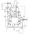
- the hot water supply apparatus is roughly divided into a hot water storage tank unit 1 having a hot water storage tank 3 for storing hot water and a heat pump unit 2 as a heating means for heating the hot water in the hot water storage tank 3 as shown in FIG. Composed.
- the hot water storage tank unit 1 includes a hot water storage tank 3, tank temperature sensors 10, 11, 12, 13, 14 that detect the temperature in the hot water storage tank 3, and a heat pump forward pipe 2 a that constitutes a circulation circuit of the heat pump unit 2.
- the heat pump unit 2 includes a heat pump cycle including a compressor, a condenser, an expansion valve, an evaporator, a hot water circulation pump, and the like (not shown).
- the hot water in the lower part of the hot water storage tank 3 is sent to the heat pump unit 2 from the heat pump forward pipe 2a, heated up, and stored by returning hot water from the heat pump return pipe 2b to the upper part of the hot water storage tank 3.
- the hot water storage tank unit 1 includes a water supply pipe 5e that introduces water into the hot water storage tank 3, a hot water discharge pipe 3a that discharges high-temperature hot water from the hot water storage tank 3, a branch pipe 5d for the water supply, and heat for heating the water supply that can heat the water supply.
- Exchanger 5 feed water heating pipe 5 b for feeding water after feed water heating, feed water bypass pipe 5 a for bypassing feed water heating heat exchanger 5, hot water mixing valve 31 for controlling the temperature of the hot water supply, water supply water channel A water supply switching valve 33 for switching is provided.
- the water supply heating heat exchanger 5 is provided in the lower part of the hot water storage tank 3.
- the tank temperature sensor 14 is provided at a location where the temperature can be detected near the bottom of the hot water storage tank.
- the tank temperature sensor 13 is provided in the vicinity of the feed water heating heat exchanger 5 (specifically, slightly above the upper end of the feed water heating heat exchanger 5).
- the tank temperature sensor 10 is provided in a place where the temperature can be detected near the upper end of the hot water storage tank 3.
- a hot water tap 9 that is opened and closed during hot water supply is connected to the outside of the hot water storage tank unit 1.
- the water supply switching valve 33 is opened ac, and the water supply is the water supply bypass pipe 5a and the water supply forward pipe 5c. Is introduced into the hot water supply mixing valve 31 and mixed with hot water from the hot water outlet pipe 3a to supply hot water.
- the hot-water supply mixing valve 31 is controlled so that the hot-water supply temperature sensor 17 provided in the hot-water supply pipe 9 a becomes the hot-water supply temperature set by the remote controller 6.
- the feed water switching valve 33 is opened bc, and the feed water is heated by the feed water heating heat exchanger 5;
- the hot water is introduced into the hot water supply mixing valve 31 through the hot water supply pipe 5b and the hot water supply pipe 5c, and hot water is mixed with hot water from the hot water outlet pipe 3a.
- the heat of the hot water can be used for hot water supply by exchanging the heat of the hot water in the hot water storage tank 3 with the hot water in the hot water storage tank 3. Since the hot water in the hot water storage tank 3 is deprived of heat, it becomes possible to improve the energy efficiency at the time of re-boiling.
- the hot-water supply mixing valve 31 is controlled so that the hot-water supply temperature sensor 17 provided in the hot-water supply pipe 9 a becomes the hot-water supply temperature set by the remote controller 6. Since the water-side temperature is high in the hot-water supply mixing valve 31, the amount of hot-water (high-temperature water from the hot water discharge pipe 3a) can be reduced, so that the amount of stored hot water can be maintained.
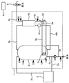
- the hot water heater of the second embodiment has a bathtub 7 connected to the hot water storage tank unit 1 of the first embodiment, and controls the temperature of the hot water beam and the hot water pipe 7 a for hot water to the bathtub 7.
- a bath return pipe 4b for returning hot water to the bathtub 7 is provided.
- the water supply switching valve 33 is opened ac, and the water is supplied to the water supply bypass pipe 5a, It introduces into the bath mixing valve 32 via the water supply going-out pipe 5c, mixes with the hot water from the hot water outlet pipe 3a, and pours hot water.
- the bath mixing valve 32 is controlled such that the bath temperature sensor 19 provided in the bath going pipe 4 a has a hot water temperature set by the remote controller 6.
- the hot water in the hot water storage tank 3 is used, the feed water switching valve 33 is opened bc, and the feed water is the heat exchanger 5 for heating the feed water. Then, the water is introduced into the bath mixing valve 32 via the feed water heating pipe 5b and the feed water outgoing pipe 5c, and mixed with the hot water from the hot water discharge pipe 3a to be poured.
- the heat of the hot water can be used for hot water supply by exchanging heat with the hot water in the hot water storage tank 3 at a relatively low temperature. Since the hot water in the hot water storage tank 3 is deprived of heat, it becomes possible to improve the energy efficiency at the time of re-boiling.
- the bath mixing valve 32 is controlled such that the bath temperature sensor 19 provided in the bath going pipe 4 a has a hot water temperature set by the remote controller 6. Since the temperature on the water supply side is high in the bath mixing valve 32, the amount of hot water (high temperature water from the hot water outlet pipe 3a) can be reduced, so that the amount of stored hot water can be maintained.
- the reheating heat exchanger 4 is provided in the upper part of the hot water storage tank 3.
- the circulation pump 8 is periodically operated, hot water in the bathtub 7 is introduced into the flow-out pipe 4a, and if the bath temperature sensor 19 is lower than the set value of the bathtub temperature by the remote controller 6, the circulation pump 8 The operation is continued, the hot water in the bathtub 7 is chased and introduced into the heat exchanger 4 to exchange heat with the hot water in the hot water storage tank 3. Since the temperature after the heat exchange is high, the temperature of the reheating temperature sensor 18 and the temperature of the reflow temperature sensor 19 are adjusted by the circulation adjustment valve 30 by the reflow temperature adjusting valve 30 and returned to the bathtub 7 for reheating. Is possible.
- the hot water used for reheating becomes warm water around 40 ° C. (generally referred to as medium temperature water).
- medium temperature water Considering that a general hot water supply temperature is, for example, about 40 ° C., such medium-temperature water is unsuitable for use in hot water supply, and therefore it is preferable to use this for the remaining heat of the water supply.
- the temperature of the hot water in the tank is decreased mainly due to generation of medium-temperature water by reheating or heat dissipation.
- a mixing valve feed water heating and mixing valve capable of adjusting the mixing ratio may be used.
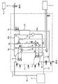
- the water heater of the third embodiment is roughly divided into a hot water storage tank unit 1 having a hot water storage tank 3 for storing hot water and a heat pump unit 2 as a heating means for heating the hot water in the hot water storage tank 3, as shown in FIG. Composed.
- the hot water storage tank unit 1 includes a hot water storage tank 3, tank temperature sensors 10, 11, 12, 13, 14 for detecting the temperature in the hot water storage tank, and a heat pump forward pipe 2 a that constitutes a circulation circuit of the heat pump unit 2. And a return pipe 2b.
- the heat pump unit 2 includes a heat pump cycle including a compressor, a condenser, an expansion valve, an evaporator, a hot water circulation pump, and the like (not shown).
- the hot water in the lower part of the hot water storage tank 3 is sent to the heat pump unit 2 from the heat pump forward pipe 2a, heated up, and stored by returning hot water from the heat pump return pipe 2b to the upper part of the hot water storage tank 3.
- the hot water storage tank unit 1 includes a water supply pipe 5e for introducing water into the hot water storage tank 3, a hot water discharge pipe 3a for discharging hot water from the hot water storage tank, a branch pipe 5d for the water supply, and heat exchange for heating the hot water that can heat the water supply. 5, a feed water heating pipe 5 b that feeds the water after the feed water heating, a feed water bypass pipe 5 a that bypasses the feed water heating heat exchanger 5, a feed water switching valve 33 that switches the feed water path, and the hot water storage tank 3.
- a hot water supply heat exchanger 40 for exchanging heat between the hot water and the hot water and a hot water supply circulation pump 41 for circulating hot water in the hot water supply heat exchanger 40 and the hot water storage tank 3.
- the water supply heating heat exchanger 5 is provided in the lower part of the hot water storage tank 3.
- the tank temperature sensor 14 is provided at a location where the temperature can be detected near the bottom of the hot water storage tank.
- the tank temperature sensor 13 is provided in the vicinity of the feed water heating heat exchanger 5 (specifically, slightly above the upper end of the feed water heating heat exchanger 5).
- the tank temperature sensor 10 is provided at a location where the temperature can be detected near the upper end of the hot water storage tank.
- a hot water tap 9 that is opened and closed during hot water supply is connected to the outside of the hot water storage tank unit 1.
- the tank temperature sensor 10 When the hot-water tap 9 is opened, the tank temperature sensor 10, the feed water temperature sensor 15 disposed on the upstream side of the hot water storage tank 3, the hot water flow rate sensor 20, and the feed water temperature sensor 16 disposed on the downstream side of the hot water storage tank 3.
- the hot water supply circulation pump 41 is controlled so that the hot water supply temperature becomes the hot water supply temperature set by the remote controller 6, and the hot water supply heat exchanger 40 exchanges heat between the hot water in the hot water storage tank 3 and the low temperature water supply, and a predetermined value is obtained. Hot water can be supplied.
- the temperature of the primary side hot water exchanged in the hot water heat exchanger 40 is slightly higher than that of the hot water due to the performance of the hot water heat exchanger 40 (specifically, water supply
- the water is returned to the hot water storage tank 3 at a temperature higher than about 2 ° C. Therefore, since all the heat is returned to the lower part of the tank without transferring it to the water supply, there is a problem that a part of the high-temperature water in the upper part of the tank is wasted.
- the energy efficiency is improved as the temperature of the liquid to be boiled is lower. Therefore, the energy efficiency can be improved by the above configuration.
- the water supply switching valve 33 is opened ac, and the water supply is the water supply bypass pipe 5a and the water supply forward pipe 5c. To the hot water supply heat exchanger 40.
- the feed water switching valve 33 is opened bc, and the feed water is heated by the feed water heating heat exchanger 5; It introduces into the hot water supply heat exchanger 40 via the feed water heating pipe 5b and the feed water outgoing pipe 5c.
- the heat of the hot water can be used for hot water supply by exchanging heat between the hot water in the hot water storage tank 3 and the hot water in the hot water storage tank 3. Since the hot water in the hot water storage tank 3 is deprived of heat, it becomes possible to improve the energy efficiency at the time of re-boiling.
- the temperature of the water supply introduced into the hot water supply heat exchanger 40 becomes high, the number of rotations of the hot water supply circulation pump 41 can be reduced, and the power consumption can be reduced.
- the amount of hot water used from the hot water outlet pipe 3a can be reduced, the amount of stored hot water can be maintained.
- low temperature water is mainly generated by direct pressure hot water supply using the hot water supply heat exchanger 40, and the temperature of the hot water in the tank is lowered due to heat dissipation.
- the hot water heater of the fourth embodiment has a bathtub 7 connected to the hot water storage tank unit 1 of the third embodiment, and controls the temperature of the hot water beam and the hot water pipe 7 a for hot water to the bathtub 7.
- a bath return pipe 4b for returning hot water to the bathtub 7 is provided.
- the bath mixing valve 32 is controlled such that the bath temperature sensor 19 provided in the bath going pipe 4 a has a hot water temperature set by the remote controller 6.
- the reheating heat exchanger 4 is provided in the upper part of the hot water storage tank 3.
- the circulation pump 8 is periodically operated, hot water in the bathtub 7 is introduced into the throat pipe 4a, and if the tub temperature sensor 19 is lower than the set value of the tub temperature by the remote controller 6, the circulation pump is operated.
- the hot water in the bathtub 7 is chased and introduced into the heat exchanger 4 to exchange heat with the hot water in the hot water storage tank 3. Since the temperature after the heat exchange is high, the temperature of the reheating temperature sensor 18 and the temperature of the reflow temperature sensor 19 are adjusted by the circulation adjustment valve 30 by the reflow temperature adjusting valve 30 and returned to the bathtub 7 for reheating. Is possible.
- the water supply switching valve 33 is opened ac, and the water is supplied to the water supply bypass pipe 5a, It introduces into the bath mixing valve 32 via the water supply going-out pipe 5c, mixes with the hot water from the hot water outlet pipe 3a, and pours hot water.
- the bath mixing valve 32 is controlled such that the bath temperature sensor 19 provided in the bath going pipe 4 a has a hot water temperature set by the remote controller 6.
- the hot water in the hot water storage tank 3 is used, the feed water switching valve 33 is opened bc, and the feed water is the heat exchanger 5 for heating the feed water. Then, the water is introduced into the bath mixing valve 32 via the feed water heating pipe 5b and the feed water outgoing pipe 5c, and mixed with the hot water from the hot water discharge pipe 3a to be poured.
- a set temperature for example, 30 ° C.
- the heat of the hot water can be used for hot water supply by exchanging the heat of the hot water in the hot water storage tank 3 with the hot water in the hot water storage tank 3. Since the hot water in the hot water storage tank 3 is deprived of heat, it becomes possible to improve the energy efficiency at the time of re-boiling.
- the bath mixing valve 32 is controlled such that the bath temperature sensor 19 provided in the bath going pipe 4 a has a hot water temperature set by the remote controller 6. Since the temperature of the water side is high in the bath mixing valve 32, the amount of hot water (high-temperature water from the outlet pipe 3a) can be reduced, so that the amount of stored hot water can be maintained.
- the hot water used for reheating becomes warm water around 40 ° C. (generally referred to as medium temperature water).
- medium temperature water is unsuitable for use in hot water supply, so it is preferable to use this for the remaining heat of the water supply.
- the temperature of the hot water in the tank is decreased due to the generation of medium or low temperature water mainly by direct pressure hot water using the reheating hot water supply heat exchanger 40, or by heat radiation. Occurs.
- a hot water circuit is provided with a heat exchanger for heating the feed water.
- a heat exchanger for heating water supply is provided in both the general hot water supply circuit and the hot water filling circuit.
- the water heater according to the present invention is not limited to the configuration of the above embodiment, and various modifications can be made without departing from the spirit of the invention.
- the water supply switching valve 33 may be a mixing valve (feed water heating and mixing valve) capable of adjusting the mixing ratio.
- the feed water heating and mixing valves 33 heats the feed water with the feed water heating heat exchanger 5.
- the water supply temperature sensor 16 is introduced from the feed water heating pipe 5b, and the water supply temperature sensor 16 is matched with the tank temperature sensor 10 so that the water supply is introduced as it is from the water supply bypass pipe 5a and becomes a temperature close to the hot water temperature set by the remote controller 6.
- the feed water heating and mixing valve 33 may be controlled to reach the set temperature of the feed water temperature sensor 16. This makes it possible to effectively use the heat at the bottom of the hot water storage tank 3.
- the feed water bypass pipe 5a and the feed water switching valve 33 are not necessarily required. If the feed water bypass pipe 5a and the feed water switching valve 33 are not used, it is inexpensive and heat of hot water generated during use. Can be used to reduce hot water and provide a water heater that can improve energy efficiency during re-boiling.
- the form of the hot water storage tank 3 may be a closed type or an open type.
- An embodiment of the open-type hot water storage tank is shown in FIG. In this water heater, a reheating heat exchanger 45 is disposed outside the hot water storage tank.
- the heating means for heating the hot water in the hot water storage tank has been described as the heat pump unit 2, but it is not limited to this, and an electric heater may be used.
- the heating means and the tank are not configured separately as in the hot water storage tank unit 1 and the heat pump unit 2, but configured as one unit. It may be done.
- the present invention provides a water heater that indirectly uses high temperature water as a heat medium for heating the water supply, and a heat medium for heating the water supply.
- a hot water heater that uses hot liquid stored in a tank for hot water supply such as a hot water heater that uses brine or the like instead of high-temperature water, it can be applied.
- Switching temperature may be what degreeC.
- Hot water storage tank unit 2 Heat pump unit 3 Hot water storage tank 4 Reheating heat exchanger 5 Heat exchanger for feed water heating 5a Feed water bypass pipe 5b Feed water heating pipe 7 Bathtub 9 Hot water taps 10, 13 Tank temperature sensor 16 Hot water temperature sensor 31 Hot water mixing valve 32 Bath mixing valve 33 Feed water switching valve (feed water heating mixing valve) 34 Pressure reducing valve 40 Hot water supply heat exchanger
Landscapes
- Engineering & Computer Science (AREA)
- Physics & Mathematics (AREA)
- Thermal Sciences (AREA)
- Chemical & Material Sciences (AREA)
- Combustion & Propulsion (AREA)
- Mechanical Engineering (AREA)
- General Engineering & Computer Science (AREA)
- Heat-Pump Type And Storage Water Heaters (AREA)
- Domestic Hot-Water Supply Systems And Details Of Heating Systems (AREA)
Abstract
Description
趣旨を逸脱しない範囲内で種々の変更が可能である。
2 ヒートポンプユニット
3 貯湯タンク
4 追い焚き熱交換器
5 給水加熱用熱交換器
5a 給水バイパス管
5b 給水加熱管
7 浴槽
9 給湯栓
10,13 タンク温度センサ
16 給水温度センサ
31 給湯混合弁
32 ふろ混合弁
33 給水切換弁(給水加熱混合弁)
34 減圧弁
40 給湯熱交換器
Claims (5)
- 高温の液体を貯留するタンクと、
前記タンク内に貯留される高温の液体を生成するための加熱手段とを備え、
前記タンク内の下部には、給湯端末に供給される給水をタンク内の下部に存在する液体
によって加熱する給水加熱用熱交換器が設けられることを特徴とする給湯機。 - 給水を前記給湯端末まで導く給湯回路が設けられ、
前記給湯回路は、前記給水加熱用熱交換器を通る給水加熱用経路と、前記給水加熱用熱
交換器をバイパスするバイパス経路とに分岐して設けられ、
前記給水加熱用経路及び前記バイパス経路に対する給水の流通状態を制御する給湯回路
制御機構を備えることを特徴とする請求の範囲第1項に記載の給湯機。 - 前記給湯回路制御機構は、給水が前記給水加熱用経路を流れる状態と、バイパス経路を
流れる状態とを切換可能に構成されることを特徴とする請求の範囲第2項に記載の給湯機。 - 前記給湯回路制御機構は、前記給水加熱用経路を流れる給水と、バイパス経路を流れる
給水の流量比を調整可能に構成されること特徴とする請求の範囲第3項に記載の給湯機。 - 前記給水加熱用熱交換器近傍の液体の温度を検知する温度センサが設けられ、
前記給湯回路制御機構による給湯回路の制御は、給水加熱用熱交換器近傍の液体の温度
に基づいて行われることを特徴とする請求の範囲第2項乃至第4項のいずれか一項に記載の給湯機。
Priority Applications (4)
| Application Number | Priority Date | Filing Date | Title |
|---|---|---|---|
| EP10837622A EP2515050A1 (en) | 2009-12-15 | 2010-12-15 | Hot water supply system |
| CN201080055067.5A CN102652244B (zh) | 2009-12-15 | 2010-12-15 | 供热水机 |
| KR1020127013276A KR101386087B1 (ko) | 2009-12-15 | 2010-12-15 | 급탕기 |
| US13/516,242 US9010281B2 (en) | 2009-12-15 | 2010-12-15 | Hot water supply system |
Applications Claiming Priority (2)
| Application Number | Priority Date | Filing Date | Title |
|---|---|---|---|
| JP2009283573A JP5452203B2 (ja) | 2009-12-15 | 2009-12-15 | 給湯機 |
| JP2009-283573 | 2009-12-15 |
Publications (1)
| Publication Number | Publication Date |
|---|---|
| WO2011074596A1 true WO2011074596A1 (ja) | 2011-06-23 |
Family
ID=44167347
Family Applications (1)
| Application Number | Title | Priority Date | Filing Date |
|---|---|---|---|
| PCT/JP2010/072525 Ceased WO2011074596A1 (ja) | 2009-12-15 | 2010-12-15 | 給湯機 |
Country Status (6)
| Country | Link |
|---|---|
| US (1) | US9010281B2 (ja) |
| EP (1) | EP2515050A1 (ja) |
| JP (1) | JP5452203B2 (ja) |
| KR (1) | KR101386087B1 (ja) |
| CN (1) | CN102652244B (ja) |
| WO (1) | WO2011074596A1 (ja) |
Cited By (2)
| Publication number | Priority date | Publication date | Assignee | Title |
|---|---|---|---|---|
| CN102331084A (zh) * | 2011-08-05 | 2012-01-25 | 侯全舵 | 组合有吸排油烟机的空气能热泵热水器 |
| CN102853540A (zh) * | 2011-06-28 | 2013-01-02 | 广州科力新能源有限公司 | 一种即热式热回收型浴室热泵热水器 |
Families Citing this family (14)
| Publication number | Priority date | Publication date | Assignee | Title |
|---|---|---|---|---|
| EP2413048B1 (de) * | 2010-07-30 | 2013-06-05 | Grundfos Management A/S | Brauchwassererwärmungseinheit |
| WO2014094854A1 (en) * | 2012-12-20 | 2014-06-26 | Electrolux Home Products Corporation N. V. | Household appliance and method of operating a household appliance |
| CN103115730A (zh) * | 2013-01-29 | 2013-05-22 | 苏州奔腾塑业有限公司 | 检测保温杯密封性的注水装置 |
| KR101620814B1 (ko) * | 2014-12-17 | 2016-05-12 | 주식회사 경동나비엔 | 감압밸브가 구비된 온수 공급 장치 |
| CN105078245A (zh) * | 2015-08-25 | 2015-11-25 | 佛山市顺德区畅联万方科技管理有限公司 | 流动加热式温开水设备 |
| JP6454655B2 (ja) * | 2016-03-08 | 2019-01-16 | 日立アプライアンス株式会社 | 貯湯式給湯機 |
| CN105780358B (zh) * | 2016-04-25 | 2017-11-03 | 常熟市新光毛条处理有限公司 | 毛条处理液循环加热装置 |
| US10890359B2 (en) * | 2016-07-26 | 2021-01-12 | Noritz Corporation | Heating and hot water supply device |
| US10989442B2 (en) * | 2016-07-26 | 2021-04-27 | Noritz Corporation | Heating and hot water supply device |
| US10323859B2 (en) * | 2016-10-27 | 2019-06-18 | King Fahd University Of Petroleum And Minerals | Water mixing system for thermoregulating water |
| US20210317997A1 (en) * | 2020-04-10 | 2021-10-14 | Harvest Thermal, Inc. | Hydronic space conditioning and water heating systems with integrated disinfecting device |
| CN111550862B (zh) * | 2020-05-09 | 2025-07-18 | 江苏苏净集团有限公司 | 一种采用二氧化碳热泵的恒温供水系统及其控制方法 |
| JP7037094B1 (ja) * | 2020-09-30 | 2022-03-16 | ダイキン工業株式会社 | 給湯装置 |
| EP4253847B1 (en) * | 2022-03-28 | 2025-08-06 | Mitsubishi Electric Corporation | System and method for providing domestic hot water |
Citations (3)
| Publication number | Priority date | Publication date | Assignee | Title |
|---|---|---|---|---|
| JPS55137448A (en) * | 1979-04-13 | 1980-10-27 | Hashimoto Sangyo Kk | Hot water supply system |
| JP2007225252A (ja) * | 2006-02-27 | 2007-09-06 | Toto Ltd | 浄水器付き電気温水器 |
| JP2008241170A (ja) * | 2007-03-28 | 2008-10-09 | Daikin Ind Ltd | ヒートポンプ式給湯装置 |
Family Cites Families (14)
| Publication number | Priority date | Publication date | Assignee | Title |
|---|---|---|---|---|
| US5564462A (en) * | 1994-10-19 | 1996-10-15 | Storch; Paul | Water conservation delivery system using temperature-controlled by-pass circuit |
| DE19932436C2 (de) * | 1999-07-12 | 2002-02-28 | Gewofag Gemeinnuetzige Wohnung | Trinkwarmwasserleitungsanlage |
| JP3758627B2 (ja) * | 2001-11-13 | 2006-03-22 | ダイキン工業株式会社 | ヒートポンプ式給湯装置 |
| US8567689B2 (en) * | 2004-09-17 | 2013-10-29 | Carrier Corporation | Sanitary operator of a hot water heat pump |
| JP4513558B2 (ja) | 2004-12-27 | 2010-07-28 | 株式会社ノーリツ | 殺菌機能付き貯湯式給湯装置 |
| JP2006329581A (ja) | 2005-05-30 | 2006-12-07 | Hitachi Appliances Inc | 電気給湯機 |
| US20060283404A1 (en) * | 2005-06-01 | 2006-12-21 | Lin Wen-Lung | Auxiliary device for a hot water device |
| JP2008045851A (ja) | 2006-08-19 | 2008-02-28 | Corona Corp | 貯湯式給湯装置 |
| JP4274273B2 (ja) * | 2007-08-23 | 2009-06-03 | ダイキン工業株式会社 | 貯湯式給湯機 |
| JP2009074750A (ja) * | 2007-09-21 | 2009-04-09 | Tokyo Electric Power Co Inc:The | 給湯システム |
| WO2010041653A1 (ja) * | 2008-10-07 | 2010-04-15 | ダイキン工業株式会社 | 温水システム |
| JP5084768B2 (ja) * | 2009-03-11 | 2012-11-28 | リンナイ株式会社 | 給湯システム |
| KR101175451B1 (ko) * | 2010-05-28 | 2012-08-20 | 엘지전자 주식회사 | 히트펌프 연동 급탕장치 |
| WO2012101804A1 (ja) * | 2011-01-27 | 2012-08-02 | 三菱電機株式会社 | ヒートポンプ装置及びヒートポンプ装置の制御方法 |
-
2009
- 2009-12-15 JP JP2009283573A patent/JP5452203B2/ja not_active Expired - Fee Related
-
2010
- 2010-12-15 EP EP10837622A patent/EP2515050A1/en not_active Withdrawn
- 2010-12-15 US US13/516,242 patent/US9010281B2/en not_active Expired - Fee Related
- 2010-12-15 WO PCT/JP2010/072525 patent/WO2011074596A1/ja not_active Ceased
- 2010-12-15 KR KR1020127013276A patent/KR101386087B1/ko not_active Expired - Fee Related
- 2010-12-15 CN CN201080055067.5A patent/CN102652244B/zh not_active Expired - Fee Related
Patent Citations (3)
| Publication number | Priority date | Publication date | Assignee | Title |
|---|---|---|---|---|
| JPS55137448A (en) * | 1979-04-13 | 1980-10-27 | Hashimoto Sangyo Kk | Hot water supply system |
| JP2007225252A (ja) * | 2006-02-27 | 2007-09-06 | Toto Ltd | 浄水器付き電気温水器 |
| JP2008241170A (ja) * | 2007-03-28 | 2008-10-09 | Daikin Ind Ltd | ヒートポンプ式給湯装置 |
Cited By (2)
| Publication number | Priority date | Publication date | Assignee | Title |
|---|---|---|---|---|
| CN102853540A (zh) * | 2011-06-28 | 2013-01-02 | 广州科力新能源有限公司 | 一种即热式热回收型浴室热泵热水器 |
| CN102331084A (zh) * | 2011-08-05 | 2012-01-25 | 侯全舵 | 组合有吸排油烟机的空气能热泵热水器 |
Also Published As
| Publication number | Publication date |
|---|---|
| KR20120087957A (ko) | 2012-08-07 |
| CN102652244B (zh) | 2015-11-25 |
| EP2515050A1 (en) | 2012-10-24 |
| JP5452203B2 (ja) | 2014-03-26 |
| KR101386087B1 (ko) | 2014-04-16 |
| US9010281B2 (en) | 2015-04-21 |
| JP2011127773A (ja) | 2011-06-30 |
| US20120255507A1 (en) | 2012-10-11 |
| CN102652244A (zh) | 2012-08-29 |
Similar Documents
| Publication | Publication Date | Title |
|---|---|---|
| JP5452203B2 (ja) | 給湯機 | |
| JP5200842B2 (ja) | 給湯装置 | |
| EP2966366B1 (en) | Heat pump water heating system | |
| CN101191665B (zh) | 热泵供热水装置 | |
| KR20130118244A (ko) | 저탕식 급탕장치 | |
| JP2009103387A (ja) | 貯湯式給湯装置 | |
| JP2006343011A (ja) | 給湯装置 | |
| JP5589943B2 (ja) | 貯湯式給湯機 | |
| JP4839141B2 (ja) | ヒートポンプ給湯装置 | |
| JP5200578B2 (ja) | 給湯装置 | |
| JP5678688B2 (ja) | ヒートポンプ給湯機 | |
| JP4778299B2 (ja) | 貯湯式給湯装置およびその給湯混合弁の待機開度変更方法 | |
| JP5423558B2 (ja) | 貯湯式給湯機 | |
| JP4752347B2 (ja) | 貯湯式給湯装置 | |
| JP2007333332A (ja) | 貯湯式暖房装置 | |
| JP6526599B2 (ja) | 熱機器 | |
| JP2011141069A (ja) | 風呂装置 | |
| JP2002364912A (ja) | 多機能給湯装置 | |
| JP6036579B2 (ja) | 給湯機 | |
| JP2015021717A (ja) | 貯湯給湯装置 | |
| JP2005315523A (ja) | 給湯装置 | |
| JP4779571B2 (ja) | 給湯装置 | |
| JP2006234210A (ja) | 貯湯式給湯器 | |
| JP4501700B2 (ja) | 給湯装置 | |
| JP2008281335A (ja) | 貯湯式給湯装置 |
Legal Events
| Date | Code | Title | Description |
|---|---|---|---|
| WWE | Wipo information: entry into national phase |
Ref document number: 201080055067.5 Country of ref document: CN |
|
| 121 | Ep: the epo has been informed by wipo that ep was designated in this application |
Ref document number: 10837622 Country of ref document: EP Kind code of ref document: A1 |
|
| ENP | Entry into the national phase |
Ref document number: 20127013276 Country of ref document: KR Kind code of ref document: A |
|
| NENP | Non-entry into the national phase |
Ref country code: DE |
|
| WWE | Wipo information: entry into national phase |
Ref document number: 13516242 Country of ref document: US Ref document number: 2010837622 Country of ref document: EP |