WO2011077489A1 - 仮想ボリュームを提供するストレージシステム - Google Patents
仮想ボリュームを提供するストレージシステム Download PDFInfo
- Publication number
- WO2011077489A1 WO2011077489A1 PCT/JP2009/007207 JP2009007207W WO2011077489A1 WO 2011077489 A1 WO2011077489 A1 WO 2011077489A1 JP 2009007207 W JP2009007207 W JP 2009007207W WO 2011077489 A1 WO2011077489 A1 WO 2011077489A1
- Authority
- WO
- WIPO (PCT)
- Prior art keywords
- page
- real page
- virtual
- tier
- frequency
- Prior art date
- Legal status (The legal status is an assumption and is not a legal conclusion. Google has not performed a legal analysis and makes no representation as to the accuracy of the status listed.)
- Ceased
Links
Images






Classifications
-
- G—PHYSICS
- G06—COMPUTING OR CALCULATING; COUNTING
- G06F—ELECTRIC DIGITAL DATA PROCESSING
- G06F3/00—Input arrangements for transferring data to be processed into a form capable of being handled by the computer; Output arrangements for transferring data from processing unit to output unit, e.g. interface arrangements
- G06F3/06—Digital input from, or digital output to, record carriers, e.g. RAID, emulated record carriers or networked record carriers
- G06F3/0601—Interfaces specially adapted for storage systems
- G06F3/0628—Interfaces specially adapted for storage systems making use of a particular technique
- G06F3/0629—Configuration or reconfiguration of storage systems
- G06F3/0632—Configuration or reconfiguration of storage systems by initialisation or re-initialisation of storage systems
-
- G—PHYSICS
- G06—COMPUTING OR CALCULATING; COUNTING
- G06F—ELECTRIC DIGITAL DATA PROCESSING
- G06F3/00—Input arrangements for transferring data to be processed into a form capable of being handled by the computer; Output arrangements for transferring data from processing unit to output unit, e.g. interface arrangements
- G06F3/06—Digital input from, or digital output to, record carriers, e.g. RAID, emulated record carriers or networked record carriers
- G06F3/0601—Interfaces specially adapted for storage systems
- G06F3/0602—Interfaces specially adapted for storage systems specifically adapted to achieve a particular effect
- G06F3/0608—Saving storage space on storage systems
-
- G—PHYSICS
- G06—COMPUTING OR CALCULATING; COUNTING
- G06F—ELECTRIC DIGITAL DATA PROCESSING
- G06F3/00—Input arrangements for transferring data to be processed into a form capable of being handled by the computer; Output arrangements for transferring data from processing unit to output unit, e.g. interface arrangements
- G06F3/06—Digital input from, or digital output to, record carriers, e.g. RAID, emulated record carriers or networked record carriers
- G06F3/0601—Interfaces specially adapted for storage systems
- G06F3/0602—Interfaces specially adapted for storage systems specifically adapted to achieve a particular effect
- G06F3/061—Improving I/O performance
-
- G—PHYSICS
- G06—COMPUTING OR CALCULATING; COUNTING
- G06F—ELECTRIC DIGITAL DATA PROCESSING
- G06F3/00—Input arrangements for transferring data to be processed into a form capable of being handled by the computer; Output arrangements for transferring data from processing unit to output unit, e.g. interface arrangements
- G06F3/06—Digital input from, or digital output to, record carriers, e.g. RAID, emulated record carriers or networked record carriers
- G06F3/0601—Interfaces specially adapted for storage systems
- G06F3/0602—Interfaces specially adapted for storage systems specifically adapted to achieve a particular effect
- G06F3/061—Improving I/O performance
- G06F3/0611—Improving I/O performance in relation to response time
-
- G—PHYSICS
- G06—COMPUTING OR CALCULATING; COUNTING
- G06F—ELECTRIC DIGITAL DATA PROCESSING
- G06F3/00—Input arrangements for transferring data to be processed into a form capable of being handled by the computer; Output arrangements for transferring data from processing unit to output unit, e.g. interface arrangements
- G06F3/06—Digital input from, or digital output to, record carriers, e.g. RAID, emulated record carriers or networked record carriers
- G06F3/0601—Interfaces specially adapted for storage systems
- G06F3/0628—Interfaces specially adapted for storage systems making use of a particular technique
- G06F3/0646—Horizontal data movement in storage systems, i.e. moving data in between storage devices or systems
- G06F3/0647—Migration mechanisms
-
- G—PHYSICS
- G06—COMPUTING OR CALCULATING; COUNTING
- G06F—ELECTRIC DIGITAL DATA PROCESSING
- G06F3/00—Input arrangements for transferring data to be processed into a form capable of being handled by the computer; Output arrangements for transferring data from processing unit to output unit, e.g. interface arrangements
- G06F3/06—Digital input from, or digital output to, record carriers, e.g. RAID, emulated record carriers or networked record carriers
- G06F3/0601—Interfaces specially adapted for storage systems
- G06F3/0628—Interfaces specially adapted for storage systems making use of a particular technique
- G06F3/0662—Virtualisation aspects
- G06F3/0665—Virtualisation aspects at area level, e.g. provisioning of virtual or logical volumes
-
- G—PHYSICS
- G06—COMPUTING OR CALCULATING; COUNTING
- G06F—ELECTRIC DIGITAL DATA PROCESSING
- G06F3/00—Input arrangements for transferring data to be processed into a form capable of being handled by the computer; Output arrangements for transferring data from processing unit to output unit, e.g. interface arrangements
- G06F3/06—Digital input from, or digital output to, record carriers, e.g. RAID, emulated record carriers or networked record carriers
- G06F3/0601—Interfaces specially adapted for storage systems
- G06F3/0668—Interfaces specially adapted for storage systems adopting a particular infrastructure
- G06F3/0671—In-line storage system
- G06F3/0683—Plurality of storage devices
- G06F3/0685—Hybrid storage combining heterogeneous device types, e.g. hierarchical storage, hybrid arrays
-
- G—PHYSICS
- G06—COMPUTING OR CALCULATING; COUNTING
- G06F—ELECTRIC DIGITAL DATA PROCESSING
- G06F3/00—Input arrangements for transferring data to be processed into a form capable of being handled by the computer; Output arrangements for transferring data from processing unit to output unit, e.g. interface arrangements
- G06F3/06—Digital input from, or digital output to, record carriers, e.g. RAID, emulated record carriers or networked record carriers
- G06F3/0601—Interfaces specially adapted for storage systems
- G06F3/0668—Interfaces specially adapted for storage systems adopting a particular infrastructure
- G06F3/0671—In-line storage system
- G06F3/0683—Plurality of storage devices
- G06F3/0689—Disk arrays, e.g. RAID, JBOD
-
- G—PHYSICS
- G06—COMPUTING OR CALCULATING; COUNTING
- G06F—ELECTRIC DIGITAL DATA PROCESSING
- G06F3/00—Input arrangements for transferring data to be processed into a form capable of being handled by the computer; Output arrangements for transferring data from processing unit to output unit, e.g. interface arrangements
- G06F3/06—Digital input from, or digital output to, record carriers, e.g. RAID, emulated record carriers or networked record carriers
- G06F3/0601—Interfaces specially adapted for storage systems
- G06F3/0668—Interfaces specially adapted for storage systems adopting a particular infrastructure
- G06F3/0671—In-line storage system
- G06F3/0673—Single storage device
Definitions
- the present invention relates to storage control to which Thin Provisioning (also called Dynamic Provisioning) is applied.
- Data migration technology is known. Data migration is generally performed on a volume basis. For example, according to Patent Document 1, all data stored in the first logical volume is migrated from the first logical volume to the second logical volume.
- storage tiering technology is known.
- a plurality of logical volumes included in a plurality of storage systems are classified into any one of a plurality of tiers, and a logical volume belonging to a certain tier is assigned to another tier.
- the plurality of tiers include, for example, a highly reliable tier and a low-cost tier.
- Thin Provisioning also called Dynamic Provisioning
- a virtual logical volume composed of a plurality of virtual storage areas (virtual pages) and a plurality of substantive storage areas (real pages) are prepared.
- a real page is allocated to the virtual page, and write target data is written to the allocated real page.
- the above-mentioned data migration technology and storage tiering technology are applied to Thin Provisioning. Further, it is assumed that the first virtual volume belongs to the first tier and the second virtual volume belongs to the second tier. In this case, all data can be migrated from the first virtual volume belonging to the first tier to the second virtual volume belonging to the second tier.
- all the data in the first virtual volume is transferred from the first tier to the second tier, but it is preferable that all the data is necessarily present in the second tier. Not exclusively.
- an object of the present invention is to appropriately arrange data in a virtual volume in accordance with Thin Provisioning.
- a plurality of the logical volumes to which at least one storage area included in the plurality of storage areas is allocated in response to a write request to at least one address included in the plurality of addresses in the logical volume is provided.
- the access status of the at least one address in the logical volume the data that has been written to the at least one address by the write request is included in the at least one storage area group.
- the storage area is shifted to at least one storage area in another storage area group included in the plurality of storage area groups.
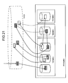
- Example 1 shows a configuration of a storage system 103.
- the relationship between various storage areas in the storage system 103 is shown.
- stores are shown.
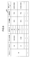
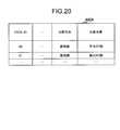
- the structure of the tier definition table 401 is shown.
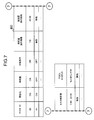
- the structure of the tier management table 402 is shown.
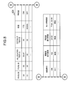
- the structure of the pool management table 403 is shown.
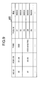
- the structure of the VVOL management table 404 is shown.
- the structure of the PVOL management table 405 is shown.
- the structure of the allocation table 407 is shown.
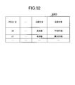
- the structure of the real page management table 408 is shown.
- the structure of the monitor table 409 is shown.
- the structure of the frequency distribution table 410 is shown.
- the structure of the migration page table 411 is shown.
- the structure of the migration definition table 412 is shown.
- the flowchart of a pool creation process is shown.
- the pool definition GUI 1700 is shown.
- the flow of a VVOL creation process is shown.
- a VVOL creation GUI 1900 is shown.
- 10 shows a VVOL management table 4404 related to Example 5 of the present invention.
- An overview of data element aggregation processing is shown.
- the flow of an information display process is shown.
- a frequency distribution GUI 2300 is shown.
- the flow of write processing write to cache memory
- the flow of destage processing is shown.
- the flow of read processing is shown.
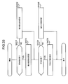
- An overview of the relationship between I / O frequency monitoring and rearrangement is shown.
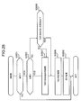
- the flow of a rearrangement process is shown.
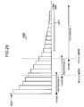
- An overview of the tear arrangement determination process is shown.
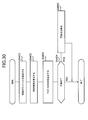
- the flow of a tear arrangement determination process is shown.
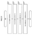
- the flow of the tier boundary value calculation process of S4402 of FIG. 30 is shown.
- 10 shows a pool management table 4403 according to Embodiment 5 of the present invention.
- 10 shows a flow of a comparison method / comparison target setting process according to Embodiment 5 of the present invention.
- the flow of the migration page table creation process in S2808 of FIG. 28 is shown.
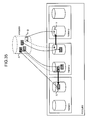
- An overview of the page-by-page migration process is shown.
- a flow of page-by-page migration processing is shown.
- the flow of a change process of a tier threshold value is shown.
- the flow of the over threshold handling process is shown.
- a plurality of storage areas provided from a plurality of storage devices are managed according to storage area attributes, and a plurality of storage area groups are managed, Providing a plurality of the logical volumes to which at least one storage area included in the plurality of storage areas is allocated in response to a write request to at least one address included in the plurality of addresses in the logical volume; According to the access status of the at least one address in the logical volume, the data that has been written to the at least one address by the write request is included in the at least one storage area group.
- a method for controlling a storage system characterized in that a storage area is migrated to at least one storage area in another storage area group included in the plurality of storage area groups.
- a method comprising The first storage area group and the second storage area group included in the plurality of storage area groups have the degree of access status suitable for each group as an attribute for each loop, and The degree of the access situation with the second storage area group is different for each group, but partially overlaps,
- the at least one storage area included in one of the plurality of storage area groups is included in the first or second storage area group and the at least one address
- the storage system control method wherein the data migration is not performed when the access status is within the partially overlapping range of the degree of the access status.
- a storage system connected to one or more hosts includes a plurality of types of physical storage device groups and a storage control device.
- the storage control device includes a storage resource, a controller connected to the plurality of types of physical storage device groups, the storage resource, and the host.
- the physical storage device group is composed of one or more physical storage devices.
- the plurality of types of physical storage device groups are the basis of a plurality of types of real page groups.
- the type of the real page group is based on the attribute of the physical storage device group on which the real page group is based.
- the real page group has a plurality of real pages.
- the controller provides one or more virtual volumes to the one or more hosts.
- the virtual volume is a virtual logical volume composed of a plurality of virtual pages.
- the virtual page is a virtual storage area.
- the real page is a substantial storage area.
- the storage resource is allocation information that is information indicating which virtual page is allocated to which virtual page, monitor information that is information indicating I / O (Input / Output) frequency for each virtual page, and real page Real page group management information, which is information including information indicating the I / O frequency range set for each group type, is stored (any format of information, such as a table format or a queue format).
- the controller receives a write command from the host, specifies a write-destination virtual page from the write command, updates the allocation information so as to allocate a free real page to the specified virtual page, and sets the allocated real page. Stores the data to be written.
- the controller updates the I / O frequency of the virtual page in the monitor information according to the I / O for the virtual page or the real page assigned to the virtual page.
- the real page is a substantial storage area, and data stored in the real page is stored in a physical storage device that is the basis of the real page. Transition process in which the controller includes the following processes (A) to (C): (A) specifying a virtual volume or virtual page whose I / O frequency specified from the monitor information does not meet a predetermined condition; (B) The data stored in the first real page in the first type real page group allocated to the specified virtual volume or virtual page is stored in the second type real page group.
- the controller performs an I / O frequency range determination process, and in the determination process, determines the I / O frequency range of various real page groups based on the monitor information.
- the controller may have at least one processor, for example.
- the storage resource may be a memory, for example.
- the host may be a computer, another storage system, or another storage control device.
- the data in the virtual volume can be rearranged in units of pages according to the I / O frequency of the virtual page.
- the data can be a group of real pages corresponding to an I / O frequency range in which the I / O frequency of the virtual page to which the real page storing the data is allocated falls.
- the controller performs the following processes (a) and (b) in the determination process: (A) Using the monitor information, creating relationship information that is information representing the relationship between the I / O frequency and the number of virtual pages; (B) Based on the relationship information, the I / O frequency range of various real page groups is determined.
- the controller performs the following processes (b1) to (b3) in the process (b): (B1) A total I / O frequency that is a total I / O frequency of all virtual pages in one or more virtual volumes to which a real page is allocated from the plurality of types of real page groups using the relationship information. Calculate (B2) Based on the ratio of performance values of various real page groups and the total I / O frequency, a boundary value that is an I / O frequency of the boundary of the real page group is calculated for each boundary of the real page group; (B3) Determine the I / O frequency range of each real page group based on the I / O frequency of each real page group and the boundary value for each boundary of the real page group.
- the performance value of the real page group is a value related to the performance determined based on the attribute of the physical storage device group that is the basis of the real page group.
- the boundary of the real page group is a boundary between the real page group and its upper and / or lower real page group.
- the maximum value and / or the minimum value of the I / O frequency range of each real page group is a value determined based on the boundary value between the real page group and its upper and / or lower real page group.
- the maximum value of the I / O frequency range is larger than the larger boundary value corresponding to the I / O frequency range and / or the I / O frequency range.
- the minimum value of the / O frequency range is smaller than the smaller boundary value corresponding to the I / O frequency range.
- the performance value of the real page group includes the number of real pages that can be a migration destination in the migration process in the real page group and the performance per real page in the real page group. It is a value calculated by multiplication with the value.
- the performance value per real page in the real page group is a value related to the performance, which is determined based on the attribute of the physical storage device group on which the real page group is based.
- the controller performs the following process in the determination process: (A) A total I / O frequency that is the total I / O frequency of all virtual pages in one or more virtual volumes to which real pages are allocated from the plurality of types of real page groups using the monitor information. To calculate; (B) Based on the ratio of performance values of various real page groups and the total I / O frequency, a boundary value that is an I / O frequency of the boundary of the real page group is calculated for each boundary of the real page group; (C) Based on the I / O frequency of each real page group and the boundary value for each boundary of the real page group, determine the I / O frequency range of each real page group, I do.
- the performance value of the real page group is a value related to the performance determined based on the attribute of the physical storage device group that is the basis of the real page group.
- the boundary of the real page group is a boundary between the real page group and its upper and / or lower real page group.
- the maximum value and / or the minimum value of the I / O frequency range of each real page group is a value determined based on the boundary value between the real page group and its upper and / or lower real page group.
- the controller performs the following processes (d) and (e) in the determination process: (D) Assuming that the data elements in the real page assigned to all virtual pages having an I / O frequency that falls within the I / O frequency range of the real page group have been transferred to the real page group, Determining whether the usage rate of a page group exceeds the rate threshold of the actual page group; (E) When the result of the determination in (d) is negative, the determined I / O frequency range is included in the real page group management information. I do.
- the usage ratio of the real page group is a ratio of the number of real pages allocated to the virtual page to the number of real pages constituting the real page group.
- the ratio threshold of the real page group is the threshold of the usage ratio.
- the controller further performs the following process (f) in the determination process: (F) When the result of the determination in (d) is affirmative, the I / O frequency range is corrected so that the usage ratio of the real page group does not exceed the percentage threshold of the real page group. I do.
- the controller further performs the following process (g) in the determination process: (G) including the corrected I / O frequency range in the real page group management information; I do.
- the I / O frequency of the virtual volume or virtual page specified from the monitor information is included in the monitor information of the virtual volume or virtual page. I / O frequency.
- the I / O frequency of the virtual volume or virtual page specified from the monitor information is different from the virtual volume in the monitor information. This is a relative value with respect to the I / O frequency of the volume or the I / O frequency of a virtual page different from the virtual page.
- the controller receives designation of whether the I / O frequency in (A) is an absolute value or a relative value.
- the I / O frequency of the virtual volume or virtual page specified from the monitor information is the I / O frequency included in the monitor information of the virtual volume or virtual page. / O frequency.
- the I / O frequency of the virtual volume or virtual page specified from the monitor information is the I / O frequency of a virtual volume different from the virtual volume in the monitor information. This is a relative value to the O frequency or the I / O frequency of a virtual page different from the virtual page.
- the I / O frequency in (A) is an average of the number of I / Os at a certain time.
- the I / O frequency in (A) is the maximum of a plurality of I / O numbers respectively corresponding to a plurality of times in a certain time zone. The number of I / Os.
- the controller designates whether the I / O frequency in (A) is an average I / O number or a maximum I / O number. receive.
- the I / O frequency in (A) is an average of the number of I / Os in a certain time.
- the I / O frequency in (A) is the maximum of the number of I / Os respectively corresponding to a plurality of times in a certain time zone. I / O number.
- the controller receives an I / O command from the host, and specifies an I / O destination virtual page from the I / O command.
- the controller updates the I / O frequency corresponding to the I / O destination virtual page in the monitor information when performing I / O to the real page allocated to the I / O destination virtual page.
- the I / O frequency corresponding to the I / O destination virtual page in the monitor information is not updated. .
- the I / O frequency of the virtual page to which the real page is allocated can be updated only when I / O is performed on the real page.
- the storage resource stores, as the monitor information, monitor information whose state is active and monitor information whose state is standby.
- the controller updates the I / O frequency in the active monitor information.
- the controller identifies the first virtual page based on the active monitor information, changes the state of the standby monitor information from standby to active,
- the I / O frequency of the specified virtual page in the monitor information whose state is changed to active is updated.
- monitoring (update) of the I / O frequency can be continued.
- the controller outputs the relation information so that the created relation information is displayed.
- the controller starts the migration process when receiving an instruction to start migration.
- ⁇ Viewpoint 21> In the storage system according to any one of the viewpoints 3 to 20, the controller starts the migration process when the usage ratio of the first real data group exceeds a predetermined ratio threshold.
- the first type real data group is the highest level real data group.
- the controller always assigns a real page from the first type of real data group to the write-destination virtual page specified from the write command.
- the controller includes a certain percentage or more of real pages allocated to the virtual volume in a certain real page group. If there is, the data in the real page in the real page group other than the certain real page group among all the real pages assigned to the virtual volume is converted into the certain real page. Move to a real page in the group.
- ⁇ Viewpoint 24> In the storage system according to the viewpoint 23, a real page assigned to the virtual page after shifting to a real page in the certain real page group is always a real page in the certain real page group.
- the controller receives a write command for specifying the first virtual page from the host after the page unit migration processing is started, and If the data transfer from the first real page to the second real page has not been started, the transfer is canceled and the data according to the write command is transferred to the real page in the second type real page group. And the allocation information is updated so that the first virtual page is assigned the real page of the write destination instead of the first real page.
- the controller receives a write command for specifying the first virtual page from the host after the page unit migration processing is started, and When data transfer from the first real page to the second real page has not started, data according to the write command is written to the first real page, and then (A) and (B )I do.
- the controller receives a write command for specifying the first virtual page from the host after the page unit migration process is started, and , If data is being migrated from the first real page to the second real page, cancel the migration, write the data according to the write command to the real page in the second type real page group, and The allocation information is updated so that the first virtual page is allocated with the real page of the write destination instead of the first real page.
- the controller receives a write command specifying the first virtual page from the host after the page unit migration processing is started, and When data is being transferred from the first real page to the second real page, the data according to the write command is written to the first real page, and then the second type from the first real page. The migration of data to the real page in the real page group is resumed.
- the controller receives a write command for specifying the first virtual page from the host after the page unit migration process is started, and When data is being transferred from the first real page to the second real page, after the transfer is completed, the data according to the write command is written to the second real page according to the allocation information.
- the controller receives a write command for specifying the first virtual page from the host after the page unit migration process is started, and When data is being transferred from the first real page to the second real page, data according to the write command is written to both the first real page and the second real page.
- the controller receives a write command for specifying the first virtual page from the host after the page unit migration process is started, and When (A) and (B) have been completed, data according to the write command is written into the second real page according to the allocation information.
- the first virtual page is a virtual page in which the last I / O time that is the latest time when the I / O is performed satisfies a predetermined condition. is there.
- the predetermined condition is that the last I / O time is past the predetermined time from the current time.
- the second type real page group is a lower real page group than the first type real page group.
- the first virtual page is a virtual page in which an I / O according to sequential access has occurred.
- the second type real page group is a lower real page group than the first type real page group.
- the controller updates the monitor information only in a predetermined time zone.
- the controller stores the monitor information every time a predetermined time zone is passed.
- the first virtual page is a virtual page in which the I / O frequency specified from the monitor information corresponding to the designated time zone does not meet a predetermined condition.
- a storage control device of a storage system connected to a host includes a storage resource and a controller connected to the storage resource and the host.
- the controller provides one or more virtual volumes to the one or more hosts.
- the virtual volume is a virtual logical volume composed of a plurality of virtual pages.
- the virtual page is a virtual storage area.
- the real page is a substantial storage area.
- the storage resource is allocation information that is information indicating which virtual page is allocated to which virtual page, monitor information that is information indicating I / O (Input / Output) frequency for each virtual page, and real page Real page group management information which is information including information indicating the I / O frequency range set for each group type is stored.
- the controller receives a write command from the host, specifies a write-destination virtual page from the write command, and allocates a free real page from any of a plurality of types of real pages to the specified virtual page.
- the information is updated, and the write target data is stored in the allocated real page.
- the controller updates the I / O frequency of the virtual page in the monitor information according to the I / O for the virtual page or the real page assigned to the virtual page.
- the real page is a substantial storage area.
- the real page group has a plurality of real pages.
- Transition process in which the controller includes the following processes (A) to (C): (A) specifying a virtual volume or virtual page whose I / O frequency specified from the monitor information does not meet a predetermined condition; (B) The data stored in the first real page in the first type real page group allocated to the specified virtual volume or virtual page is stored in the second type real page group. Move to 2 real pages; (C) updating the allocation information to allocate the second real page instead of the first real page to a first virtual page that is a virtual page to which the first real page is allocated; I do.
- the predetermined condition is to fall within the I / O frequency range of the first type real page group.
- the second type real page group is a real page group in which the I / O frequency range is within the I / O frequency of the virtual volume or virtual page specified in (A).
- the controller performs an I / O frequency range determination process, and in the determination process, determines the I / O frequency range of various real page groups based on the monitor information.
- the viewpoints 1 and 2 described above are viewpoints taking a storage system control method as an example
- the viewpoints 3 to 35 are viewpoints taking a storage system as an example
- the viewpoint 36 takes a storage controller as an example.
- any of these aspects is also applicable to storage systems, storage control devices, storage control methods, storage systems or storage control device control methods, storage systems or storage control devices, computer programs (e.g., ( e.g., ( , A computer program for storage control, or a computer program executed by a storage system or storage control device).
- an object may be represented by a combination of a name and an ID instead of a reference sign.
- a logical volume is represented by reference numeral 500
- logical volume 500 when a logical volume with ID 00 is represented, it is represented as “logical volume # 00”.
- data stored in one real page is referred to as a “data element”.
- data elements stored in a real page assigned to a virtual page may be represented by “data elements in a virtual page” or similar expressions.
- FIG. 1 shows an outline of the first embodiment of the present invention.
- a host device (hereinafter referred to as a host) 101 is connected to the storage system 103. There may be one host 101 or a plurality of hosts 101.
- the storage system 103 provides a virtual volume (hereinafter referred to as VVOL (Virtual Volume)) 203 to the host 101 and has a plurality of types of tiers 303.
- VVOL Virtual Volume
- the VVOL 203 is a virtual logical volume according to Thin Provisioning, that is, a logical volume not based on a physical storage device (hereinafter referred to as PDEV).
- the VVOL 203 is composed of a plurality of virtual pages 207.
- the virtual page 207 is a virtual storage area. Assume that there is one VVOL # 00 as the VVOL 203.
- the virtual page #b in the VVOL #a will be referred to as “virtual page # (ab)”.
- the Thin Provisioning VVOL 203 is provided to the host 101 as having a virtual capacity, and a real page is allocated in response to a write request from the host 101 to an address of a virtual page.
- One VVOL 203 is provided to one or more hosts 101. When provided to a plurality of hosts 101, the VVOL 203 is shared by the plurality of hosts 101.
- Tier 303 is composed of a plurality of real pages 209.
- the real page 209 is a substantial storage area.
- the tier 303 for example, it is assumed that there are two tiers # 01 and # 02.
- the real page #d in the tier #c is referred to as “real page # (cd)”.
- the tier 303 may be composed of, for example, one or more real volumes (hereinafter referred to as RVOL (Real Volume)).
- RVOL Real Volume
- the RVOL is a substantive logical volume, that is, a logical volume based on PDEV.
- Each of the plurality of tiers 303 in one pool is set to be used for one or a plurality of VVOLs 203 in a state before data migration.
- the host 101 is generally a computer, but may be another storage system instead of the computer.
- the host 101 transmits an I / O (Input / Output) command to the storage system 103.
- the I / O command is, for example, a write command or a read command, and has I / O destination information.
- the I / O destination information is information indicating the I / O destination. For example, the ID of the VVOL 203 (for example, LUN (Logical Unit Number)) and the address of the I / O destination (for example, LBA (Logical) Block Address)). From the I / O destination information, the I / O destination VVOL 203 and the virtual page 207 are specified.
- the storage system 103 receives a write command from the host 101 and specifies the virtual page # (00-C) as the write destination based on the I / O destination information included in the write command. If any real page 209 is not assigned to the specified virtual page # (00-C), the storage system 103 assigns any free (unassigned) real page # (01) to the virtual page 207. -D) is allocated, and the data element to be written in accordance with the write command is written to the allocated real page (01-D).
- data migration is performed on a page basis.
- the storage system 103 performs the following processing: * The data element in the real page # (01-D) assigned to the virtual page # (00-C) is transferred to the free (unassigned) real page # (02-E); * Change the allocation source of virtual page # (00-C) from real page # (01-D) to real page # (02-E); * Update the status of real page # (01-D) to free (unallocated status) I do.
- Whether or not to migrate data migration and where to place the migration destination tier are determined based on the tier range described below.
- the tear range is determined automatically.
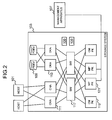
- FIG. 2 shows the configuration of the storage system 103.
- the storage system 103 includes a plurality of PDEVs 105, a storage control device connected to the plurality of PDEVs 105, and a power supply unit 100.
- the plurality of PDEVs 105 include a plurality of types of PDEVs such as SSD (Solid State Drive) and HDD (Hard Disk Drive).
- HDDs include HDD-FC (Fibre Channel), HDD-SATA (Serial ATA), and HDD-SAS (Serial Attached SCSI).
- the storage control device has a controller and a plurality of CMPKs (cache memory packages) 119 connected to the controller.
- the controller includes a plurality of CHAs (channel adapters) 111, a plurality of DKAs (disk adapters) 113, a plurality of MPPKs (microprocessor packages) 121, and a SW (switch) 117.
- CHAs channel adapters
- DKAs disk adapters
- MPPKs microprocessor packages
- SW switch
- the number of CMPK 119 may be more than two.
- the power supply unit 100 supplies electric power based on electric power from a commercial power supply to each of the packages 119, 111, 113, 121, and 117.
- the CHA 111 is an interface device connected to the host 101.
- the CHA 111 receives an I / O command (write command or read command) from the host 101 and transfers the received I / O command to one of the plurality of MPPKs 121.
- the CHA 111 has a protocol chip 112 and an LR (Local Router) 114.
- the protocol chip 112 performs protocol conversion for communication with the host 101.
- the LR 114 transfers the received I / O command to the MPPK 121 corresponding to the I / O destination specified from the I / O destination information included in the I / O command.
- the DKA 113 is an interface device connected to the HDD 105.
- the DKA 113 reads data from the HDD 105 and transfers the data to a DRAM (Dynamic Random Access Memory) of the CMPK 119 or writes the data from the CMPK 119 to the HDD 105.
- DRAM Dynamic Random Access Memory
- the MPPK 121 is a device having one or a plurality of MPs (microprocessors).
- the MP processes an I / O command from the CHA 111.
- a plurality of packages that is, CHA 111, DKA 113, CMPK 119, and MPPK 121 are connected to SW 117.
- the SW 117 controls connection between PKs (packages).
- CMPK119 has a volatile memory and / or a non-volatile memory.
- the CMPK 119 includes, for example, a storage area (hereinafter referred to as a cache memory or CM for short) in which a data element that is a target of I / O with respect to the virtual page 207 (real page 209) is stored.
- the CMPK 119 has a storage area for storing various information and computer programs. Information and computer programs will be described later.
- a management device 107 is connected to the storage system 103.
- the management device 107 is a computer having a display device and an input device, for example.
- the administrator can perform various settings for the storage system 103 from the management apparatus 107.
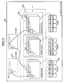
- FIG. 3 shows the relationship between various storage areas in the storage system 103.
- one or more RGs 301, one or more pools 201, and one or more VVOLs 203 are managed from the lower level to the higher level.
- RG301 is an abbreviation for RAID group.
- One RG 301 is composed of the same type of PDEV.
- the PDEV type is defined, for example, at least one of performance and unit cost.
- the performance is, for example, a data I / O speed or a response time (a time length from when a command is received from the host until a response is returned).
- the unit cost is a price (for example, so-called bit cost) required to store data of unit size.
- RG # 00 is composed of a plurality of SSDs
- RG # 01 is composed of a plurality of HDD-SASs
- RG # 02 is composed of a plurality of HDD-SATAs.
- capacitance of several PDEV which comprises one RG is the same, for example.
- the pool 201 is a set of real pages 207. Specifically, for example, the pool 201 is composed of one or more RVOLs 205, and each RVOL 205 is composed of one or more real pages 207.
- RVOL constituting the pool 201 is abbreviated as “PVOL”.
- Real pages 207 constituting one pool 201 are hierarchized. That is, a plurality of tiers 303 exist in one pool 201.
- the tier 303 exists, for example, for each type of RVOL.
- the number of tiers 303 is also three. Therefore, one type of RVOL 205 corresponding to that tier belongs to one tier 303.
- tier # 00 is a type called SSD
- an RVOL based on RG 301 configured by SSD belongs
- tier # 01 is a type called HDD-SAS, which is HDD-SAS.
- the RVOL based on the configured RG 301 belongs, and the tier # 03 is of the type HDD-SATA, and the RVOL based on the RG 301 configured by the HDD-SATA belongs.
- the tier 303 is not necessarily provided strictly for each RVOL type, and a plurality of RVOLs 205 based on similar types of RGs may belong to the same tier 303.
- the VVOL 203 is associated with an allocation source pool 201 from one or more pools 201. Further, a tier 303 (hereinafter referred to as an allocation tier) 303 that can be used as an allocation source is associated with the VVOL 203 from the selected pool 201. In addition, one of one or more allocation tiers 303 is associated with the VVOL 203 as a default tier 303. According to FIG. 3, the allocation tiers of VVOL # 01 are tiers # 00 and # 02.
- a plurality of RVOLs may be based on one RG if they belong to the same tier, but if they belong to different tiers, respectively. , Each of which is based on a separate RG.
- a plurality of real pages are sequentially allocated to a plurality of virtual pages of one or a plurality of VVOLs 203 related to the same tier 303, the real pages are sequentially selected across the RGs related to the tier 303. It is desirable to do.
- the real pages are sequentially selected from sequentially different RGs in consideration of the relationship with the RG. This makes it possible to improve access performance.
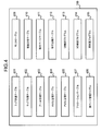
- FIG. 4 shows information and computer programs stored in the CMPK 119.
- a table is adopted as an example of information, but the information may be in a format other than the table (for example, a queue format).
- the CMPK 119 includes, as information, a tier definition table 401, a tier management table 402, a pool management table 403, a VVOL management table 404, a PVOL management table 405, an allocation table 407, a real page management table 408, a monitor table 409, a frequency distribution table 410, A migration page table 411 and a migration definition table 412 are stored. Further, the CMPK 119 is a UI control program 413 that is a program that controls UI (User Interface), an I / O control program 414 that is a program that controls I / O, and a program that performs relocation as computer programs. The rearrangement program 415 is stored. Note that at least one of these tables and the computer program may be stored in a storage resource other than the CMPK 119. For example, at least one computer program and / or the migration page table 411 may be stored in a memory in the MPPK 121.
- an object is specified using an ID, but may be specified using at least one of a name and a number instead of or in addition to the ID.
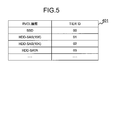
- FIG. 5 shows the configuration of the tier definition table 401.
- the tier definition table 401 is a table representing a tier definition. Specifically, for example, the table 401 represents the relationship between the RVOL type and the tier ID. According to the table 401, a tier to which an ID “00” is assigned is prepared as a tier corresponding to the RVOL type “SSD”.
- FIG. 6 shows the configuration of the tier management table 402.
- the tier management table 402 is a table for managing information related to tiers. Specifically, for example, the table 402 has, for each tier, a pool ID, a tier ID, a tier range, a PVOL ID, a tier threshold, a usage rate, and a real page ID. Taking one tier (hereinafter referred to as “target tier” in the description of FIG. 6) as an example, these information elements are specifically as follows.
- “Pool ID” is the ID of the pool having the target tier.
- * “Tier ID” is the ID of the target tier. From the tier ID, the type of PDEV that is the basis of the PVOL belonging to the target tier is uniquely specified.
- Tier range is a range of the load (for example, I / O frequency) of a real page that should exist in the target tier.
- PVOL ID is an ID of a PVOL belonging to the target tier.
- Tier threshold is a threshold of the usage rate of the target tier.
- User ratio is a use ratio of the target tier, that is, a ratio of the number of allocated real pages to the number of real pages constituting the target tier.
- Real page ID is an ID of all real pages belonging to the target tier.
- the tier threshold is set for each tier, but instead, one tier threshold is set for one pool, and the one tier is the one pool. It may be common for all tiers of the.
- FIG. 7 shows the configuration of the pool management table 403.
- the pool management table 403 is a table for managing information related to the pool. Specifically, for example, the table 403 has, for each pool, a pool ID, tiering, rearrangement, automatic execution, rearrangement execution cycle, rearrangement execution time, monitor time zone, and pool status. Taking a single pool (hereinafter referred to as “target pool” in the description of FIG. 7) as an example, these information elements are specifically as follows. * “Pool ID” is the ID of the target pool. * “Hierarchization” is whether or not to stratify the actual page in the target pool.
- “ON” means tiering (that is, a plurality of tiers are provided in the target pool), and “OFF” means that tiering is not performed (that is, tiers are not provided in the target pool).
- “Relocation” is whether or not to relocate the data elements in the target pool.
- “ON” means that rearrangement is performed, and “OFF” means that rearrangement is not performed.
- the important thing regarding the monitoring of the I / O frequency is that the I / O frequency is not updated unless the I / O is actually performed on the real page allocated to the I / O destination VVOL or the virtual page.
- the I / O frequency is updated when I / O is performed on a given real page. This point will also be described in the later-described write process and read process.
- Automatic execution is whether the relocation of the data elements in the target pool is automatically started or manually started. “ON” means that the rearrangement is automatically started, and “OFF” means that the rearrangement is started manually.
- the “relocation execution cycle” is a cycle in which data elements in the target pool are rearranged. For example, “1 day” means that rearrangement is started every day (24 hours).
- Relocation execution time is the time at which relocation of data elements in the target pool is started.
- Monitoring time zone is a time zone for monitoring the I / O frequency of the real page assigned to the VVOL to which the target pool is assigned.
- Pool status is the status of the target pool.
- Monitoring means that the I / O frequency of the VVOL to which the target pool is allocated or the virtual page in the VVOL is being monitored, and the data element is not being relocated.
- Relocating means that data elements have been relocated (relocation within the target pool or data elements from the target pool to another pool) It means being in the middle of being.
- Non-monitoring means neither I / O frequency monitoring nor data element relocation.
- FIG. 8 shows the configuration of the VVOL management table 404.
- the VVOL management table 404 is a table for managing information related to the VVOL. Specifically, for example, the table 404 includes, for each VVOL, a VVOL ID, a PVOL ID, an allocation tier ID, a default tier ID, a capacity, a rearrangement, an automatic execution, a rearrangement execution cycle, a rearrangement execution time, and a monitoring time zone.
- the rearrangement, automatic execution, rearrangement execution cycle, rearrangement execution time, and monitoring time zone are the same as the information elements in the pool management table 403, but the information elements in this table 404 (for example, “ If the value of “relocation”) is different from the value of the same information element (for example, “relocation”) in the pool management table 403, the value in this table 404 may be prioritized.
- the value of the information element is set for one pool, and as a result, the value can be reflected in the settings for all the VVOLs to which the pool is assigned. Can be set.
- VVOL ID is the ID of the target VVOL.
- PVOL ID is an ID of a pool (hereinafter, allocated pool) allocated to the target VVOL.
- Allocation Tier ID is an ID of a tier that is allocated to the target VVOL among a plurality of tiers that the allocation pool has. A real page is allocated from the allocation tier to the virtual page in the target VVOL.
- Default Tier ID is the ID of the default tier.
- the default tier is a tier that provides a real page that is initially allocated to a write-destination virtual page from the host 101.
- Capacity is the capacity of the target VVOL.
- Relocation is whether or not to relocate data elements in the target VVOL.
- ON means that rearrangement is performed, and “OFF” means that rearrangement is not performed.
- ON the I / O frequency of the target VVOL or its virtual page is monitored, and when “OFF”, the I / O frequency of the target VVOL or its virtual page is not monitored.
- Automatic execution is whether the relocation of data elements in the target VVOL is automatically started or manually started.
- the “ON” means that the rearrangement is automatically started, and “OFF” means that the rearrangement is started manually.
- the “relocation execution cycle” is a cycle in which data elements in the target VVOL are rearranged.
- Relocation execution time is the time at which the rearrangement of data elements in the target VVOL is started.
- Monitoring time zone is a time zone for monitoring the I / O frequency of the target VVOL or virtual page.
- FIG. 9 shows the configuration of the PVOL management table 405.
- the PVOL management table 405 is a table for managing information related to PVOL. Specifically, for example, the table 405 has RG ID, PDEV ID, type, PVOL ID, and capacity for each PVOL. Taking one PVOL (hereinafter referred to as “target PVOL” in the description of FIG. 9) as an example, these information elements are specifically as follows.
- RG ID is the ID of the RG that is the basis of the target PVOL.
- PDEV ID is the ID of all PDEVs constituting the RG that is the basis of the target PVOL.
- * “Type” is the type of the target PVOL. This is the same as the type of PDEV that is the basis of the target PVOL. For example, if the RVOL type is “SSD”, the type of the target PVOL is also “SSD”.
- PVOL ID is the ID of the target PVOL.
- Capacity is the capacity of the target PVOL.
- FIG. 10 shows the configuration of the allocation table 407.
- the allocation table 407 is a table representing which virtual page is allocated to which virtual page.
- the table 407 has a VVOL ID, a virtual page ID, a pool ID, a real page ID, and a tier ID for each virtual page.
- VVOL ID is the ID of the VVOL having the target virtual page.
- Virtual page ID is the ID of the target virtual page.
- Pool ID is the ID of the pool assigned to the VVOL having the target virtual page.
- * “Real page ID” is an ID of a real page assigned to the target virtual page.
- * “Tier ID” is an ID of a tier having a real page allocated to the target virtual page.
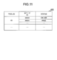
- FIG. 11 shows the configuration of the real page management table 408.
- the real page management table 408 is a table for managing the status of each real page. Specifically, for example, the table 408 has a pool ID, a real page ID, and a status for each real page. Taking one real page (hereinafter referred to as “target real page” in the description of FIG. 11) as an example, these information elements are specifically as follows. * “Pool ID” is the ID of the pool having the target real page. * “Real page ID” is the ID of the target real page. * “Status” is the status of the target real page. Status values include, for example, “in use” and “free”. “In use” means that the target real page has been assigned to any virtual page. “Free” means that the target real page is not assigned to any virtual page, and therefore can be assigned to any virtual page.
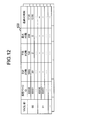
- FIG. 12 shows the configuration of the monitor table 409.
- the monitor table 409 exists for each VVOL.
- a table 409 is a table representing the I / O frequency of the virtual page.
- the table 409 will be described by taking one VVOL (hereinafter referred to as “target VVOL” in the description of FIG. 12) as an example.
- the table 409 has, for example, a VVOL ID, a virtual page ID, a total number of I / Os, an average number of I / Os, a maximum number of I / Os, and a final I / O time for each virtual page.
- VVOL ID is the ID of the VVOL having the target virtual page (that is, the target VVOL).
- Virtual page ID is the ID of the target virtual page.
- Total number of I / Os is the number of I / Os performed on the target virtual page during the monitoring time period.
- the “average I / O number” is a value calculated by dividing the value of the “total I / O number” by a predetermined time.
- “Maximum number of I / Os” is the largest number of I / Os among a plurality of I / Os (I / Os for the target virtual page) in a plurality of time zones constituting the monitor time zone.
- “Last I / O time” is the latest time when I / O was performed on the target virtual page.
- Two tables 409 are used alternately. Specifically, for example, when rearrangement is executed, a migration page table 411 described later is created using the table 409 for the latest monitoring time zone at the time of execution, and the other table 409 is used. Thus, the I / O frequency is monitored.
- the table 409 that is used may be referred to as an active table 409, and the table 409 that is not used may be referred to as a standby table 409.
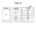
- FIG. 13 shows the configuration of the frequency distribution table 410.
- the frequency distribution table 410 is a table representing the correlation between the number of I / Os and the number of virtual pages. This table 410 is created based on the monitor table 409. As the number of I / Os, at least one of the total number of I / Os, the average number of I / Os, and the maximum number of I / Os in the table 409 described above may be employed.
- FIG. 13 is an example in which the average number of I / Os is employed. That is, the table 410 shown in FIG. 13 represents the number of virtual pages for each average I / O number. As can be seen from FIG. 13, the number of virtual pages having an average I / O count of “0” is “561”.
- This table 410 (or a graph created based on this table 410) is displayed on the management apparatus 107. The administrator can manually instruct the storage system 103 to start rearrangement of data elements based on the table 401 (or a graph based thereon).
- the frequency distribution table 410 may be updated as the monitor table 409 is updated, or may be created based on the table 409 when the administrator instructs the display of the frequency distribution.
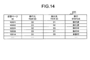
- FIG. 14 shows the configuration of the migration page table 411.
- the migration page table 411 is a table created based on the monitor table 409 when data is migrated in units of pages.
- a table 411 represents the relationship between the migration source and the migration destination.
- the table 411 includes a virtual page ID, a migration source tier ID, a migration destination tier ID, and a migration status for each migration target virtual page.
- target virtual page Taking one virtual page (hereinafter referred to as “target virtual page” in the description of FIG. 14) as an example, these information elements are specifically as follows.
- “Virtual page ID” is the ID of the target virtual page.
- * “Migration source tier ID” is an ID of a tier having a real page (migration source real page) assigned to the target virtual page.
- Migration Destination Tier ID is the ID of the tier that is the migration destination of the data element.
- the real page of the transfer destination is any free real page in the tier.
- Migration status is the status of migration for the target virtual page. As the value of “migration status”, for example, “migrated”, “migrating”, and “not migrated” are available.
- “Migrated” means that the data element has been migrated from the migration source real page to any real page in the migration destination tier.
- Migrating means that the data element is being migrated from the migration source real page to any real page in the migration destination tier.
- Non-migrated means that the migration of the data element from the migration source real page to any real page in the migration destination tier has not yet started.
- the migration page table 411 may include other types of information elements related to the migration source instead of or in addition to the virtual page ID.
- the ID of the real page assigned to the virtual page may be included in the table 411.
- the migration page table 411 may include other types of information elements related to the migration destination instead of or in addition to the migration destination tier ID.
- a free real page in the migration destination tier may be specified based on the tables 402 (FIG. 6) and 408 (FIG. 11), and the ID of the specified real page may be included in the table 411.
- the status of the specified real page may be updated from “free” to “in use” (or another status (for example, “reserve”).
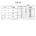
- FIG. 15 shows the configuration of the migration definition table 412.
- the migration definition table 412 represents a migration-related definition for each VVOL.
- the table 412 has a VVOL ID, a tier maintenance, an allocation tier ID, and a storage threshold for each VVOL.
- VVOL ID is the ID of the target VVOL.
- Allocation Tier ID is the ID of the allocation tier of the target VVOL.
- Storage threshold is a threshold of the storage ratio of the allocation tier. This threshold is set for each allocation tier.
- the “storage ratio” is as follows for one allocation tier (hereinafter, “target allocation tier” in the description of this paragraph). That is, the storage ratio is how much data elements of all data elements in the target VVOL are stored in the target allocation tier.
- the storage threshold is set for each tier, but instead, one storage threshold is set for one pool, and that one tier is the one pool. It may be common for all tiers of the.
- the processing performed by the computer program is actually performed by an MP (microprocessor) that executes the computer program.
- the MP is in the MPPK 121 (see FIG. 2).
- FIG. 16 shows a flow of pool creation processing.
- a pool newly created by the pool creation processing is referred to as a “target pool”.
- the UI control program 413 receives a pool creation instruction from the administrator through the management apparatus 107. Then, the program 413 performs the following preparation process, for example. * The program 413 adds a new record of the target pool to the tables 402 (FIG. 6), 403 (FIG. 7), and 408 (FIG. 11). * The program 413 receives the designation of PVOL from the administrator through the management apparatus 107. Specifically, for example, the program 413 displays information (for example, ID, type, etc.) regarding the RVOL and receives designation of the RVOL as the PVOL.
- information for example, ID, type, etc.
- S1602 to S1605 are performed for each designated RVOL. Taking one RVOL (hereinafter referred to as “target RVOL” in the description of FIG. 16) as an example, S1602 to S1605 will be described.
- the program 413 specifies the type of the specified RVOL.
- the CMPK 119 stores an RVOL management table having an ID, a capacity, a type (for example, SSD, HDD-SAS) for each RVOL, and the program 413 is designated from the RVOL management table.
- the type of the RVOL that has been specified is specified.
- the program 413 determines from the tier management table 403 whether or not a tier corresponding to the specified RVOL type already exists in the target pool. If the result of this determination is negative, S1604 is performed, and if the result of this determination is affirmative, S1605 is performed.
- the program 413 identifies the tier ID corresponding to the identified RVOL type from the tier definition table 401. Then, the program 413 adds the identified tier ID for the target pool to the table 402 (FIG. 6).
- the program 413 adds the target RVOL to the tier corresponding to the specified RVOL type (hereinafter referred to as “target tier” in this paragraph). Specifically, for example, the program 413 registers the ID of the target RVOL as the PVOL ID corresponding to the tier ID of the target tier in the table 402 (FIG. 6).
- the program 413 determines whether or not S1602 and subsequent steps have been performed for all designated RVOLs. If there is an RVOL in which the processing after S1602 is not performed in the designated RVOL, S1602 and subsequent steps are performed for that RVOL.
- the program 413 displays a pool definition GUI (Graphical User Interface). Then, the program 413 receives various settings through the GUI.
- GUI Graphic User Interface
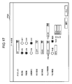
- FIG. 17 shows a pool definition GUI 1700.
- the ID of the target pool is displayed.
- the program 413 can also display the IDs of pools other than the target pool (that is, existing pools) in response to a predetermined tool (for example, pull-down menu) being operated by the administrator.
- the GUI 1700 also displays information elements “hierarchy”, “relocation”, “automatic execution”, “execution cycle”, “execution time” to be set in the table 403 (FIG. 7) for the pool indicated by the displayed ID. ”,“ Monitor time zone ”, and“ tier threshold value ”, and an input tool used by the administrator to input values.
- an input tool in the present embodiment an arbitrary tool such as a radio button, a check box, and a text input field can be adopted.
- the GUI 1700 can make one threshold common to all tiers of the target pool, or set a threshold for each tier of the target pool. Yes.
- the existing pool ID can also be displayed on the GUI 1700
- the setting of the existing pool desired by the administrator can be changed using the GUI 1700.
- the program 413 displays a warning on the management apparatus 105 as an inappropriate tier threshold.
- the tier threshold value may not be registered in the table 402 (FIG. 6).
- the program 413 updates the table. Specifically, for example, the program 413 performs the following processing. * The program 413 is input to the GUI 1700 in FIG. "Is registered in the table 403 (FIG. 7). * The program 413 divides the target pool into a plurality of real pages, and adds the IDs of the plurality of real pages to the tables 402 (FIG. 6) and 408 (FIG. 11).
- the real page capacity may be common to all pools. Therefore, the number of real pages configuring the target pool may depend on the capacity of the target pool (the total capacity of the PVOL configuring the target pool).
- the capacity of the real page may be different for each PVOL. Specifically, for example, the capacity of a real page constituting a PVOL based on a RAID 5 (4D + 1P) RG and the capacity of a real page constituting a PVOL based on a RAID 6 (4D + 2P) RG may be different. This is because the number of parity stored in one real page is different.
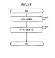
- FIG. 18 shows the flow of VVOL creation processing.
- a VVOL newly created by the VVOL creation process is referred to as “target VVOL”.
- the UI control program 413 displays a VVOL creation GUI. Then, the program 413 receives various settings through the GUI.
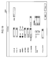
- FIG. 19 shows a VVOL creation GUI 1900.
- the ID of the target VVOL is displayed.
- the program 413 can also display the ID of a VVOL (existing VVOL) other than the target VVOL in response to a predetermined tool (for example, pull-down menu) being operated by the administrator.
- a predetermined tool for example, pull-down menu
- the GUI 1900 displays the information elements “pool ID”, “capacity”, “relocation”, “automatic execution”, “execution cycle”, “information” to be set in the table 404 (FIG. 8) for the VVOL represented by the displayed ID.
- An input tool used by the administrator to input values of “execution time” and “monitor time zone” is provided.
- the GUI 1900 identifies the tier ID corresponding to the input pool ID from the table 402 (FIG. 6), and displays all the identified tier IDs.
- the GUI 1900 has an input tool used by the administrator to input values of “allocation tier”, “storage threshold”, and “default tier” for the VVOL represented by the displayed ID.
- the administrator uses these input tools to determine which of the multiple tiers of the pool (pool allocated to the VVOL) represented by the input pool ID is to be assigned tier, and which of the assigned tiers is The “default tier” can be entered, and the storage threshold for each assigned tier can be entered.
- the program 413 updates the table. Specifically, for example, the program 413 performs the following processing.
- the program 413 is input to the GUI 1900 in FIG.
- the values of “allocation tier ID” and “default tier ID” are registered in the table 404 (FIG. 8).
- the program 413 calculates the number of virtual pages constituting the target VVOL based on the capacity of the target VVOL.
- the program 413 registers the ID of the target VVOL and the virtual page IDs for the calculated number of virtual pages in the table 407 (FIG. 10).
- the program 413 creates the table 409 (FIG. 12) if the “relocation” is “ON” for the target VVOL. This is because the I / O frequency is monitored during the monitoring time period.
- virtual page IDs corresponding to the calculated number of virtual pages are registered.
- the program 413 registers “allocation tier ID” and “storage threshold” for the target VVOL in the table 412 (FIG. 15).
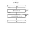
- FIG. 22 shows a flow of information display processing.
- the UI control program 413 receives a display command from the management device 107 (S2201), and displays information specified by the display command on the management device 107 (S2202).
- the types of information that can be displayed include, for example, at least one of the tables 401 to 412 (or information obtained by processing the table (eg, graph, summary, etc.)).
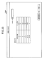
- FIG. 23 shows a frequency distribution GUI 2300.
- the frequency distribution GUI 2300 is displayed in S2202 of FIG. Specifically, for example, in S2201 of FIG. 22, the management apparatus 107 transmits a frequency distribution display command designating the VVOL ID desired by the administrator in accordance with a request from the administrator.
- the program 413 extracts a frequency distribution corresponding to the VVOL ID specified by the command from the table 410 (FIG. 13), and the extracted frequency distribution is shown in FIG. As shown in FIG.
- the frequency distribution is displayed in a table format, but may be displayed in another format such as a graph format instead of or in addition to the frequency distribution.
- the administrator looks at the frequency distribution displayed on the GUI 2300 and determines whether or not to migrate the data element in the desired VVOL. For example, if the administrator thinks that there are a large number of virtual pages with a high average I / O count, the administrator may instruct the storage system 103 to migrate the data elements in the desired VVOL (for example, in the GUI 2300) You can press the “Migrate” button).
- the frequency distribution is used as a determination material for the administrator to determine whether or not to perform data migration (migration of data elements in the VVOL). In other words, if the data migration is performed automatically, the frequency distribution need not be calculated.
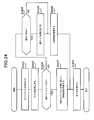
- FIG. 24 shows a flow of write processing (write to cache memory).
- the I / O control program 414 receives a write command from the host 101.
- the program 414 specifies the write-destination VVOL and virtual page from the I / O destination information included in the received write command.
- a plurality of virtual pages are often specified. This is because the size of write target data is usually larger than the capacity of one virtual page.
- S2403 and subsequent steps are performed for each identified virtual page.
- target virtual page the data element to be written to the target virtual page.
- the program 414 determines whether the ID of the target virtual page exists in the migration page table 411. If the result of this determination is negative, S2404 to S2406 are performed, and if the result of this determination is affirmative, S2407 to S2408 are performed.
- the program 414 determines whether a real page is assigned to the target virtual page based on the allocation table 407 (FIG. 10). If the result of this determination is negative, S2405 is performed.
- the program 414 performs the following processing.
- the program 414 identifies the pool corresponding to the write-destination VVOL and the default tier in the pool based on the VVOL management table 404 (FIG. 8).
- the program 414 specifies a free real page in the specified default tier based on the tier management table 402 (FIG. 6) and the real page management table 408 (FIG. 11).
- the program 414 assigns the specified real page to the target virtual page. That is, the program 414 stores the allocated real page ID, the tier ID having the real page, and the pool ID having the tier in the column corresponding to the ID of the target virtual page in the allocation table 407 (FIG. 10). And register.
- the program 414 may identify a free real page from the allocation tier corresponding to the write destination VVOL, and allocate the identified real page to the target virtual page.
- the program 414 updates the value of “use ratio” of the tier (referred to as “allocation source tier” in the description of S2403) having the allocated real page in the table 402 (FIG. 6).
- the program 414 determines whether or not the updated value of the “use ratio” of the allocation source tier exceeds the value of the “tier threshold” of the allocation source tier (hereinafter referred to as “determination Z”).
- the value of the “tier threshold” of the allocation source tier is a value registered in the table 402 (FIG.
- the program 414 may perform at least one of the following (a) and (b) if the result of the determination Z is affirmative.
- the program 414 may notify the management apparatus 107 (and / or the host 101 that has sent the write command) of the error. If the administrator learns an error about the allocation source tier, the administrator can add an RVOL to the allocation source tier.
- the program 414 calls the rearrangement program 415.
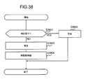
- the rearrangement program 415 performs the processing shown in FIG. The process shown in FIG. 38 will be described later.
- the program 414 secures a CM area for the data element stored in the target virtual page from the cache memory.
- the program 414 secures a CM area according to the “migration status” value corresponding to the target virtual page in the migration page table 411. Specifically, for example, it is as follows.
- the program 414 updates the “migration status” corresponding to the target virtual page to “migrated”. As a result, data elements are not migrated for the target virtual page. In other words, the migration of data elements for the target virtual page is canceled.
- the program 414 assigns the determined write destination real page to the target virtual page instead of the original real page. That is, the program 414 stores the ID of the write-destination real page and the ID of the tier having the real page (migration destination tier ID) in the column corresponding to the ID of the target virtual page in the allocation table 407. Overwrite.
- the program 414 updates the “status” of the original real page assigned to the target virtual page in the real page management table 408 (FIG. 11) to “free”.
- the program 414 updates the “status” of the real page (the determined write destination real page) newly assigned to the target virtual page in the table 408 to “in use”. (Specific example A2) *
- the program 414 secures a CM area and determines a real page (real page in the migration source tier) assigned to the target virtual page as a write destination. More specifically, for example, if the data element in any free real page in the migration destination tier is not in the cache memory, the program 414 has a CM area (for example, in the real page allocated to the target virtual page). An area where the data element exists) is secured, and a real page (real page in the migration source tier) allocated to the target virtual page is determined as a write destination.
- the program 414 may update the “migration status” corresponding to the target virtual page to “suspended”. Thereby, for example, data migration by the rearrangement program 415 is not performed for the target virtual page. Note that the value of the “migration status” may be returned from “suspended” to “not migrated” when a destage described later is completed by the program 414, for example.
- the destage is performed after the “migration status” corresponding to the target virtual page is updated to “migrated”. Therefore, the write destination (destination destination) is a real page in the migration destination tier. This is because at that time, a real page in the migration destination tier is allocated to the target virtual page. (Specific example B3) * The program 414 secures a CM area.
- the destage is performed while the “migration status” corresponding to the target virtual page is “migrating”, and the data element includes the real page assigned to the target virtual page, Destaged to both real pages in the migration destination tier (so-called double write is performed).
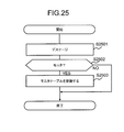
- FIG. 25 shows a flow of destage processing.
- the I / O control program 414 performs destage processing for each data element constituting the write target data.
- the program 414 performs destage. That is, the program 414 writes a data element (dirty data element) that has not been written to the real page among the plurality of data elements existing in the cache memory to the real page.
- the destage destination real page is a real page (real page specified from the allocation table 407) assigned to the virtual page that is the write destination of the real page.
- the program 414 may update the “migration status” to “not migrated”.
- the program 414 determines whether it is necessary to update the monitor table 409 based on the table 403 (FIG. 7) or 404 (FIG. 8).
- the table 404 (FIG. 8) may be prioritized. Specifically, for example, the program 414 performs the following two determinations P and Q.
- Decision P The program 414 determines whether or not “relocation” corresponding to the pool having the actual page of the destage destination in S2501 (hereinafter referred to as “target pool” in the description of FIG. 25) is “ON”.
- the program 414 determines whether or not the current time is within the time period represented by the value of the “monitor time period” corresponding to the target pool. If the result of this determination Q is negative, S2503 is not performed. On the other hand, if not only the determination P but also the result of the determination Q is affirmative, S2503 is performed (that is, the monitor table 409 needs to be updated).
- the program 414 updates the monitor table 409. Specifically, for example, it is as follows. * The program 414 updates the active monitor table 409 corresponding to the target VVOL if the “page unit migration” corresponding to the target VVOL is “ON” in the table 412 (FIG. 15). Specifically, for example, the program 414 updates (for example, increments by 1) the value of “total number of I / Os” corresponding to the write destination virtual page of the destaged data element in the active monitor table 409. In addition, the value of “last I / O time” is updated. In addition, for example, the program 414 adds the time at the destage time for the write destination virtual page to the I / O history table.
- the ID of the write destination virtual page may be recorded in the I / O history table.
- the program 414 may update the “average I / O number” and “maximum I / O number” in the active monitor table 409 later.
- FIG. 26 shows the flow of read processing.
- the I / O control program 414 receives a read command from the host 101. Then, the program 414 identifies the read-source VVOL and virtual page from the I / O destination information included in the received read command.
- the program 414 determines whether there is data to be read on the cache memory. If the result of this determination is negative, S2603 is performed, and if the result of this determination is affirmative, S2602 is performed.
- the program 414 transmits the read target data on the cache memory to the host 101.
- the monitor table 409 corresponding to the read-source VVOL is not updated. This is because no I / O is performed on the actual page.
- the program 414 determines whether a real page is allocated to the virtual page specified in S2600. If the result of this determination is negative, S2604 is performed, and if the result of this determination is affirmative, S2605 is performed.
- the program 414 transmits a predetermined response (for example, data representing zero) to the host 101.
- the program 414 reads data elements from one or more real pages (one or more real pages specified from the allocation table 407) respectively assigned to one or more virtual pages specified in S2600.
- the program 414 transmits the read target data composed of these data elements to the host 101.
- the program 414 waits until the “migration status” is updated to “migrated” for the virtual page whose “migration status” is “migrating”. Thereafter, the program 414 reads data elements from one or more real pages (one or more real pages specified from the allocation table 407) respectively assigned to one or more virtual pages specified in S2600. The program 414 transmits the read target data composed of these data elements to the host 101.
- the program 414 determines whether it is necessary to update the monitor table 409 based on the table 403 (FIG. 7) or 404 (FIG. 8).
- the table 404 (FIG. 8) may be prioritized. Specifically, for example, the program 414 performs the following two determinations V and W.
- Decision V The program 414 determines whether the “relocation” corresponding to the pool (hereinafter referred to as “read source pool” in the description of FIG. 26) assigned to the read source VVOL is “ON”, or Then, it is determined whether or not “relocation” corresponding to the read source VVOL is “ON”.
- the program 414 updates the monitor table 409. Specifically, for example, it is as follows. * The program 414 updates the active monitor table 409 corresponding to the read-source VVOL if the “page unit shift” corresponding to the read-source VVOL is “ON” in the table 412 (FIG. 15). . Specifically, for example, the program 414 updates (for example, increments by 1) the value of “total number of I / Os” corresponding to the read source write destination virtual page in the active monitor table 409, and The value of “last I / O time” is updated. Further, for example, the program 414 adds the time at the time of reading for the read-source virtual page to the above-described I / O history table.
- the ID of the read source virtual page may be recorded in the I / O history table.
- the program 414 may update the “average I / O number” and “maximum I / O number” in the active monitor table 409 later.
- FIG. 27 shows an overview of the relationship between I / O frequency monitoring and relocation.
- the monitor table 409 is updated.
- the monitor table 409 is not updated.
- the frequency distribution table 410 is updated. Note that the frequency distribution table 410 does not have to be prepared in advance. For example, when the administrator instructs the display of the frequency distribution, the frequency distribution table 410 is created based on the monitor table 409. A frequency distribution may be displayed on the basis. Note that a monitor table 409 may be displayed instead of the frequency distribution.
- Relocation processing includes tier determination processing and migration processing.
- a migration page table 411 is created.
- the table 411 may be created based on the I / O frequency represented by the monitor table 409 and the tier range in the tier management table 402 (FIG. 6).
- page-based data migration is performed based on the created migration page table 411.
- the rearrangement process may be performed when the usage ratio of a certain tier exceeds the tier threshold value of the tier, and may be performed periodically (for example, every time indicated by the value of “relocation execution time”). It may be broken.
- FIG. 28 shows the flow of the rearrangement process.
- FIG. 28 is a flow for one VVOL (referred to as “target VVOL” in the description of FIG. 28).
- the rearrangement program 415 determines whether to perform data migration for the target VVOL. Specifically, for example, the following processing is performed. * The program 415 determines whether or not “automatic execution” corresponding to the target VVOL is “ON” in the VVOL management table 404 (FIG. 8). When there is no “automatic execution” value setting corresponding to the target VVOL, the program 415 uses the pool assigned to the target VVOL in the pool management table 403 (FIG. 7) (hereinafter, “target pool” in the description of FIG. 28). It is determined whether “automatic execution” corresponding to “)” is “ON”.
- the program 415 determines whether or not a tear range is set by the administrator. If the result of this determination is negative, S2808 is performed after S2807 is performed, and if the result of this determination is negative, S2808 is performed without performing S2807.
- the program 415 performs a tear range determination process. Through this process, the tear range is determined. There are several possible methods for determining the tear range. For example, a plurality of types of tier ranges may be prepared in advance, and the program 415 may select an arbitrary tier range from the plurality of types of tier ranges for each tier.
- the program 415 performs a tier determination process.
- the migration page table 411 is created as described above.
- the program 415 performs page-by-page migration processing according to the created migration page table 411.
- data migration in units of pages data elements are migrated from a real page in one tier to a real page in another tier in the target pool.
- the page unit migration process will be described in detail later.
- FIG. 34 shows the flow of the migration page table creation process in S2808 of FIG.
- the program 415 selects the first virtual page of the target VVOL.
- the program 415 determines whether a real page is assigned to the selected virtual page. If the result of this determination is negative, S3405 is performed, and if the result of this determination is affirmative, S3403 is performed.
- the program 415 determines whether or not to change the tier in which the data element in the real page assigned to the selected virtual page should exist. Specifically, for example, it is as follows. * The program 415 identifies from the table 402 (FIG. 6) a tier (“target tier” in the description of S3403) having a real page assigned to the selected virtual page. * The program 415 calculates the I / O frequency of the selected virtual page (for example, among the total I / O number, average I / O number, and maximum I / O number represented by the active monitor table 409 corresponding to the target VVOL).
- the data elements in the real page assigned to the selected virtual page should be migrated from the target tier to another tier based on the “tier range” value corresponding to the target tier. Judge whether or not. For example, if the I / O frequency of the selected virtual page does not fall within the tier range corresponding to the target tier of the selected virtual page, it is determined that the data element should be migrated.
- S3403 If the result of the determination in S3403 is negative, S3405 is performed, and if the result of the determination is positive, S3404 is performed.
- the program 415 executes the I / O frequency of the selected virtual page (for example, out of the total I / O number, average I / O number, and maximum I / O number represented by the active monitor table 409 corresponding to the target VVOL).
- the migration destination tier is determined based on at least one) and a value of “tier range” corresponding to another allocation tier in the pool having the target tier.
- an allocation tier allocation tier of the target VVOL
- the program 415 registers the ID of the selected virtual page, the ID of the target tier, the ID of the determined migration destination tier, and the migration status “not migrated” in the migration destination page table 411.
- step S3406 The program 415 determines whether or not the selected virtual page is a virtual page at the end of the target VVOL. If the result of this determination is negative, step S3406 is performed, and if the result of this determination is affirmative, the transition page table creation process ends.
- the program 415 selects a virtual page next to the virtual page selected immediately before from the target VVOL. Thereafter, S3402 and subsequent steps are performed for the selected virtual page.
- This moving page table creation process creates a moving page table 411 for page-by-page migration processing.
- FIG. 35 shows an overview of the page-by-page migration process.
- the data element in the real page assigned to the virtual page is free of the data in the migration destination tier corresponding to the virtual page. Move to real page.
- a migration destination real page is assigned to the virtual page instead of the migration source real page.
- there are data elements that are transferred to a higher tier by this transfer process and there are data elements that are transferred to a lower tier.
- data elements in the virtual page can be arranged in a tier suitable for the I / O frequency of the virtual page.
- a higher tier range is set for the upper tier and a lower tier range is set for the lower tier.
- tier # 11 is a high-speed and highly-reliable tier (for example, a tier whose RVOL type is “SSD”), and a high tier range is set.
- tier # 13 is a low-speed or low-reliability tier (for example, a tier whose RVOL type is “HDD-SATA”) and a low tier range is set.
- tier # 12 is the default tier of VVOL # 50 and a medium tier range is set.
- the data element to be written to the virtual page constituting the VVOL # 50 is once written to the real page in the default tier # 12. Thereafter, for example, when the I / O frequency of a certain virtual page #A in the VVOL # 50 becomes high enough to be within a high tier range, the virtual page #A is assigned to that virtual page #A.
- the data elements in the real page #X are transferred from the tier # 12 to the tier # 11.
- the virtual page #B is assigned to that virtual page #B.
- the data elements in the actual page #Y are transferred from tier # 12 to tier # 13.
- the data elements in the VVOL are appropriately tiered (physical storage). Resources).
- FIG. 36 shows a flow of page-by-page migration processing.
- the relocation program 415 updates the “pool status” of the pool assigned to the target VVOL to “relocating”.
- the program 415 selects the top record of the created migration page table 411.
- the program 415 selects a free real page from the migration destination tier represented by the selected record, and the data elements stored in the migration source real page in the migration source tier in the selected real page (migration destination real page) To migrate.
- the migration source real page is a real page assigned to the target virtual page.
- the program 415 updates the table. Specifically, for example, it is as follows. * The program 415 updates the allocation table 407 so that the migration destination real page is assigned to the virtual page represented by the selected record (hereinafter, “selected virtual page” in the description of S3605) instead of the migration source real page. . That is, the program 415 associates the ID of the migration destination real page and the ID of the migration destination tier with the selected virtual page. * The program 415 updates the I / O frequency (for example, the active table 409) of the selected virtual page. Specifically, for example, the total number of I / Os of the selected virtual page or target VVOL is incremented by one. * The program 415 updates the “use ratio” value of the migration destination tier in the table 402 (FIG. 6).
- step S3608 The program 415 determines whether or not the selected record is a terminal record in the virtual page table 411. If the result of this determination is negative, step S3608 is performed, and if the result of this determination is affirmative, the transition process ends.
- the program 415 selects a record next to the record selected immediately before from the virtual page table 411. Thereafter, S3603 and subsequent steps are performed for the selected record.
- the program 415 may determine whether or not the usage rate of the migration destination tier exceeds the tier threshold value of the migration destination tier, assuming that the data element has been migrated to the migration destination tier. If it is determined that the number exceeds, the program 415 may skip S3603 to S3606 and perform S3607 (that is, the program 415 may not perform data element migration for the selected record).
- the program 415 increases the number of free real pages to the migration destination tier by performing the rearrangement process for the VVOL having the migration destination tier as the allocation tier, and then starts S3603 Also good.
- the program 415 may determine whether the usage rate of the migration destination tier exceeds the tier threshold value of the migration destination tier. If it is determined that the number has exceeded, the program 415 may display a warning on the management apparatus 107 and / or perform a relocation process on the VVOL with the migration destination tier as the allocation tier, thereby freeing the migration destination tier. You can increase the number of real pages.
- the UI control program 413 can accept a change in the tier threshold from the administrator.
- FIG. 37 shows the flow of the tier threshold value changing process.
- the program 413 receives the pool ID and tier ID and the changed tier threshold value for the tier ID.
- the program 413 determines whether or not the “use ratio” value corresponding to the pool ID and tier ID received in S3701 exceeds the changed tier threshold value.
- the program 413 displays an error on the management apparatus 107 when the result of the determination in S3702 is affirmative.
- the program 414 or 415 may determine whether the updated value of the “use ratio” exceeds the value of the “tier threshold value” corresponding to the tier. If the result of this determination is affirmative, the program 414 or 415 may perform the threshold value excess handling process shown in FIG.
- FIG. 38 shows a flow of processing for dealing with over-threshold values.
- the program 414 or 415 determines whether or not the “pool status” of the pool having a tier whose usage ratio exceeds the tier threshold is “relocating” (S3801).
- the program 414 or 415 issues a warning to the management apparatus 107 or the host 101 (S3802).
- the warning may include, for example, the ID of the tier whose usage rate has exceeded the tier threshold, the ID of the pool having the tier, and the value of “pool status” of the pool (“relocating”).
- the program 414 or 415 issues a warning to the management apparatus 107 or the host 101 (S3803), and rearrangement processing is performed so that the usage rate of the tier is less than or equal to the tier threshold value of the tier. (FIG. 28) is executed (S3804).
- the warning in S3803 may include, for example, the ID of the tier whose usage rate has exceeded the tier threshold, the ID of the pool having the tier, and a message indicating that the relocation processing is performed for the pool. .
- data element aggregation processing may be performed.
- FIG. 21 shows an overview of data element aggregation processing.
- the I / O control program 414 or the rearrangement program 415 periodically or when the data element is written to the real page for the VVOL # 39 (for example, at the end of the page-by-page migration process), the VVOL # 39.
- the program 414 or 415 determines whether there is an allocation tier whose storage ratio exceeds the storage threshold in the allocation tiers # 00, # 01, and # 03 of the VVOL # 39.
- the program 414 or 415 When there is an allocation tier whose storage ratio exceeds the storage threshold, the program 414 or 415 stores the data elements in the allocation tiers # 01 and # 03 (data elements in the VVOL # 39) other than the allocation tier # 00. , The allocation tier # 00 (specifically, for example, a free real page of the allocation tier # 00).
- the program 414 always assigns an allocation tier to the virtual page.
- a real page may be allocated from # 00.
- the program 414 or 415 may perform the following (x) or (y).
- the program 414 does not transfer the data elements in the allocation tiers # 01 and # 03 to the allocation tier # 00.
- the program 414 increases the number of free real pages to the allocation tier # 00 by moving the data elements in the VVOL other than the target VVOL and in the allocation tier # 00 to another tier.
- the tear range can be automatically determined in S2807 of FIG.
- the tear range is determined, for example, by executing a tear range determination program (not shown) on the MP.
- target pool in the description of automatic determination of the tier arrangement
- FIG. 29 shows an overview of the tear range determination process.
- tier # 01 is the highest
- tier # 02 is the second highest
- tier # 03 is the lowest tier.
- tier # 01 has the highest performance potential
- tier # 02 has the second highest performance potential
- tier # 03 has the lowest performance potential.
- “Performance potential” is the weight of the arrangement of data elements in the rearrangement process. The performance potential will be described in detail later.
- the tier arrangement determination program acquires the frequency distribution 4300 for the target pool by aggregating the frequency distributions of all VVOLs to which the target pool is assigned.
- the horizontal axis of the frequency distribution is the I / O frequency (load), and the vertical axis is the number of virtual pages.
- the tier range determination program determines the tier range in order from the upper tier to the lower tier (or from the lower tier to the upper tier).
- the tier range is determined in the order of tiers # 01, # 02, and # 03.
- processing performed for determining the tear range for each tier will be described (in FIG. 29, the upper limit of the tier range is a diamond mark and the lower limit of the tier range is a round mark).
- ⁇ Determination of Tier 1 for Tier # 01 >> * The tier range determination program sets infinity as the upper limit of tier # 1 of tier # 01. That is, infinity is set as the upper limit of the tier range of the highest tier. * In the frequency distribution 4300, the tear range determination program accumulates the number of virtual pages from the highest I / O frequency to the lowest, as indicated by an arrow 4301. When the cumulative value reaches the performance potential of the tier # 01, the tier range determination program calculates the I / O frequency corresponding to the number of virtual pages added immediately before reaching the performance potential of the tier # 01 as the tier (0 -1) Set as a boundary value (boundary value between tier # 00 and tier # 01).
- the tier range determination program sets an I / O frequency lower than the tier (0-1) boundary value by a certain margin as a lower limit of tier # 1 of tier # 01.
- the lower limit is an I / O frequency lower than the tier (0-1) boundary value by a predetermined percentage (for example, an I / O frequency lower by 10%).
- the Tier Arrangement determination program assumes that the data elements in all virtual pages that have an I / O frequency that falls within Tier 1 have been transferred to Tier # 01, and the usage rate of Tier # 01 is Tier # 01 It is determined whether or not the tier threshold is exceeded. If the result of this determination is affirmative, the tier range determination program corrects the tier range 1 so that the usage rate of tier # 01 does not exceed the tier threshold value of tier # 01.
- the tier range determination program sets an I / O frequency that is higher than the tier (0-1) boundary value by a certain margin as the upper limit of tier range 1 of tier # 02.
- the upper limit is an I / O frequency that is a predetermined percentage higher than the tier (0-1) boundary value (for example, an I / O frequency that is 10% higher).
- the tier range determination program accumulates the number of virtual pages in the frequency distribution 4300 from the tier (0-1) boundary value to the lower side.
- the tier range determination program calculates the I / O frequency corresponding to the number of virtual pages added immediately before reaching the performance potential of tier # 02 as tier (1 -2) Set as a boundary value (boundary value between tier # 01 and tier # 02). * The tier range determination program sets an I / O frequency lower than the tier (1-2) boundary value by a certain margin as the lower limit of tier # 2 of tier # 02. * The tier arrangement determination program assumes that the data elements in all virtual pages that have an I / O frequency that falls within tier arrangement 2 have been transferred to tier # 02, and the usage ratio of tier # 02 is tier # 02. It is determined whether or not the tier threshold value is exceeded. If the result of this determination is affirmative, the tier range determination program corrects tier range 2 so that the usage rate of tier # 02 does not exceed the tier threshold value of tier # 02.
- ⁇ Determination of Tier 3 for Tier # 03 >> * The tier range determination program sets an I / O frequency that is higher than the tier (1-2) boundary value by a certain margin as the upper limit of the tier # 03 tier range 3. * The tear range determination program sets zero as the lower limit of the tear range 2 of the tier # 02. That is, zero is set as the lower limit of the tier range of the lowest tier. * The Tier Arrangement determination program assumes that the data elements in all virtual pages that have an I / O frequency that falls within Tier 3 have been migrated to Tier # 03, and the usage rate of Tier # 03 is Tier # 03 It is determined whether or not the tier threshold value is exceeded. If the result of this determination is affirmative, the tier range determination program corrects the tier range 3 so that the usage rate of tier # 03 does not exceed the tier threshold value of tier # 03.
- tier ranges 1 to 3 are determined.
- the reason why the margin of the tier boundary value is given to the upper and / or lower limits of the tier range is to prevent frequent data element migration in accordance with fluctuations in the I / O frequency. Specifically, for example, when there is no margin and the I / O frequency of a certain virtual page frequently exceeds or falls below the tier (0-1) boundary value, the data elements in the virtual page are frequently It will be transferred to Tier # 01 or transferred to Tier # 02. However, if a margin is provided as described above, the frequency of such a transition can be reduced.
- FIG. 30 shows a flow of the tear range determination process.
- the “effective actual page number” is the total number of real pages that can become data element migration destinations in the rearrangement process among all the real pages constituting the target tier.
- the pool may be provided with real pages that are not used as the migration destination in the rearrangement process so that the write-target data element from the host can be written during the rearrangement process.
- the “performance level” is a performance potential per unit capacity (for example, one real page) of the target tier.
- “RG effective capacity” in (Expression 2) is, for example, the total number of real pages that store data elements for the RG that is the basis of the target tier.
- the ratio of the read weight and the write weight may be considered as the performance level instead of or in addition to the value K.
- the ratio includes, for example, I / O status from the host, cache memory status (for example, allocation of dirty data elements and clean data elements (data elements already stored in real pages)), RG RAID level It may be changed based on at least one of them.
- the performance level may be set manually by the administrator.
- the tier range determination program performs a tier boundary value calculation process. That is, the tier range determination program calculates the tier boundary value based on the performance potential calculated for each tier of the target pool.
- the tier range determination program calculates a tier range for each tier based on the calculated tier boundary values.
- the tear range determination program determines whether or not the tear range is inappropriate for each tier. More specifically, taking one tier (hereinafter referred to as “target tier” in the description of S4403 and S4405) as an example, for example, the tier range determination program includes an I / O frequency that falls within the tier range of the target tier. Assuming that the data elements in all the virtual pages are transferred to the target tier, it is determined whether the usage rate of the target tier exceeds the tier threshold value of the target tier.
- the tear range determination program displays a warning on the management apparatus 107 or sets the size so that the usage rate of the target tier does not exceed the tier threshold value of the target tier. To correct.
- FIG. 31 shows the flow of the tier boundary value calculation process in S4402 of FIG.
- the tear range determination program acquires the frequency distribution of the target pool by aggregating the frequency distribution of all VVOLs to which the target pool is allocated.
- the frequency distribution can be acquired using the monitor table 409 corresponding to each VVOL to which the target pool is assigned.
- the tear arrangement determination program calculates the total I / O frequency of the target pool. Specifically, the tear range determination program sums up the I / O frequencies of all virtual pages of all VVOLs to which the target pool is allocated.
- the tier range determination program calculates the distribution I / O frequency for each tier of the target pool based on the total I / O frequency calculated in S4502. Specifically, the tier range determination program distributes the total I / O frequency calculated in S4502 to a plurality of tiers in the target pool. Specifically, for example, the tier range determination program distributes the total I / O frequency to the plurality of tiers based on the performance potential ratio of the plurality of tiers calculated in S4401 of FIG.
- allocation of tier # 01 The I / O frequency is 4000 (7000 ⁇ (4 / (4 + 2 + 1))
- the distributed I / O frequency of tier # 02 is 2000 (7000 ⁇ (2 / (4 + 2 + 1))
- the distributed I / O frequency of tier # 01 is 1000. (7000x (1 / (4 + 2 + 1)).
- the tier range determination program determines a tier boundary value based on the distribution I / O frequency of each tier in the target pool. For example, in the example of S4503, the tier (0-1) boundary value is 2000, and the tier (1-2) boundary value is 1000.
- an appropriate tier range corresponding to the entire I / O status of the target pool is set for each tier based on the performance potential of each tier and the frequency distribution of the target pool. Can do.
- the default tier is always the tier with the maximum I / O performance (for example, I / O speed or response time) in the VVOL allocation tier (for example, the highest of the allocation tiers). Higher tier). This is to increase the VVOL I / O performance as much as possible.
- the data element to be written to the VVOL may be arranged in a higher allocation tier as possible. However, control is performed so that the used capacity of the allocated tier does not exceed the tier threshold value of the allocated tier.
- a evacuation tier may be provided in common with each pool or a plurality of pools.
- the programs 414 and 415 normally do not write data elements to the evacuation tier, either by writing according to a write command from the host or by migration processing in the rearrangement processing.
- the program 414 or 415 for example, if the usage rate of the tier to which the data element is written (hereinafter “target tier” in the description of this paragraph) exceeds the tier threshold value of the tier, The data elements in the page (or the data elements in the real page in the target tier assigned to the virtual page whose I / O frequency does not fit in the target tier's tier range) are transferred to the evacuation tier.
- the program 414 or 415 may assign the migration destination real page in the evacuation tier to the virtual page assigned to the migration source real page in the target tier instead of the migration source real page. Thereafter, the program 414 or 415 adds the tier range in which the I / O frequency of the virtual page allocated to the real page in the save tier is set to the real page in the save tier. Stored data elements may be migrated.
- the evacuation tier may be, for example, a tier composed of the same type of RVOL as the highest tier.
- the default tier need not be set.
- the data element to be written from the host 101 to the VVOL may be written to the upper tier as much as possible.
- the data element may be written in a tier one lower than the upper tier.
- VVOL I / O frequency may be calculated by summing up the I / O frequencies for each virtual page included in the monitor table 409B.
- the page-by-page migration process can be interrupted.
- the relocation program 415 receives an interruption instruction from the administrator, the migration status “migrating” is processed until the migration status “migrated” is reached, and then the page-by-page migration process is suspended.
- the program 415 may resume the migration process based on the migration page table 411 after a certain time after receiving the interruption instruction or when receiving a restart instruction.
- the program 415 may discard the migration page table 411 when receiving an interruption instruction, and create the migration page table 411 based on the active monitor table 409 in the next migration processing.
- the Thin Provisioning VVOL 203 is allocated with a real page in response to a write request from the host 101 to a certain address of the virtual page.
- the present invention is limited to this case.
- the following examples are also preferable. This is because even in these examples, it is possible to reduce the capacity actually used.
- the first example is as follows. That is, for some virtual pages of a plurality of virtual pages of the VVOL 203 or for some areas included in each virtual page of the VVOL 203, the host 101 receives a write request to a certain address of the virtual page. If the real area has been allocated in advance (pre-allocation), and the already allocated area is not sufficient and further allocation is required in response to a write request from the host 101 to an address of a virtual page, Additional real space is allocated.
- the second example is as follows. That is, a plurality of virtual pages of the VVOL 203 are real areas or control areas in which zero data is stored in advance before receiving a write request to a certain address of the virtual page from the host 101 (these areas are SSD or the like). Is temporarily allocated (temporary allocation), and data is stored from the temporary allocation area in response to a write request from the host 101 to an address of a virtual page. The assignment destination is changed to the actual page to be changed (this allocation). In this case, if a read request is received from the host 101 to an address with a virtual page before the actual allocation, zero data stored in the real area of the temporary allocation destination or the control area is returned to the host 101. become.
- the plurality of pools 201 are managed by one table so as to manage the plurality of pools 201 in a unified manner.
- the present invention is not limited to this, and a real page is provided for each pool 201.
- the type of the tier 303 is not limited to being classified for each attribute such as SSD, HDD-SAS, and HDD-SATA described in the present embodiment. It is also preferable to classify by attribute such as a device, for example, a device composed of a semiconductor storage medium such as a flash memory. In this case, the attribute of the virtual page associated with each tier 303 and the attribute of each real page included in each tier 303 are also classified for each attribute such as SSD, HDD-SAS, HDD-SATA described in this embodiment.
- the classification is not limited to the above, and classification is performed for each attribute such as an HDD having an FC interface, a storage device that is not in the HDD format, for example, a device configured by a semiconductor storage medium such as a flash memory, and the like.
- the type of the tier 303 is not limited to being classified only by the attribute of the storage device type, but is an attribute that combines the storage device type and a RAID type such as RAID1 to RAID5, or the storage device. It is also preferable to classify each attribute by combining the device type, the performance (access speed, etc.) of the storage device, the storage capacity, and the RAID type such as RAID1 to RAID5. In these cases, the attribute of the virtual page associated with each tier 303 and the attribute of each real page included in each tier 303 are not limited to being classified only by the attribute of the storage device type. Attributes combining device type and RAID type such as RAID1 to RAID5, attributes combining storage device type and performance (access speed, etc.) and storage capacity of the storage device and RAID types such as RAID1 to RAID5 It will be classified for each.
- Example 2 of the present invention will be described. At that time, differences from the first embodiment will be mainly described, and description of common points with the first embodiment will be omitted or simplified (this applies to the third and later embodiments).
- a page-by-page migration process is performed based on the last I / O time for each VVOL or each virtual page.
- the final I / O time is registered in the monitor table 409 when a data element is written on a real page.
- the rearrangement program uses the last I / O time of the virtual page as a transition page. A virtual page to be registered in the table 411 is determined.
- a virtual page whose last I / O time is past a predetermined time from the current time may be registered in the migration page table 411.
- the migration destination of the data element in the virtual page may be a lower tier than the tier having the data element in the virtual page. This is because a data element in a virtual page with an old last I / O time is unlikely to be input / output in the future, and it is considered preferable to arrange it in a lower tier.
- page-by-page migration processing is performed based on which access pattern is sequential access or random access.
- the HDD seek time can be shortened when the PDEV that is the base of the I / O destination RVOL is the HDD.
- the degree of performance degradation is small because of sequential access.
- by shifting the sequentially accessed data to the inexpensive and low-performance PDEV more of the real pages based on the high-performance PDEV can be freed for other randomly accessed data. For this reason, an improvement in I / O performance of the entire storage system can be expected.
- an access pattern for the virtual page of the I / O destination is displayed, for example, an allocation table. 407 is registered. In the allocation table 407, the execution frequency for each access pattern may be written for each virtual page.
- the rearrangement program 415 uses the migration page corresponding to the virtual page as the migration destination. You can select a lower tier. Further, for example, the rearrangement program 415 determines the data elements in the real page even if the I / O frequency of the virtual page is higher than the maximum value of the tier range of the tier having the real page assigned to the virtual page. It is not necessary to make it a migration target.
- the two monitor tables 409 are stored in the CMPK 119 or other storage resources so that they cannot be edited at a predetermined timing, instead of being used alternately.
- the monitor table 409 representing the Monday monitor result may be stored as the Monday table 409
- the monitor table 409 representing the Saturday monitor result may be stored as the Saturday table 409 separately from the Monday monitor table 409.
- the rearrangement program 415 determines whether to save the active monitor table 409 immediately before the rearrangement by a method such as inquiring an administrator. In the case of saving, immediately before the rearrangement process, the program 415 saves the monitor table 409 in the management apparatus 107 or another storage resource. The program 415 selects which monitor table 409 to be referred to for creating the migration page table 411 from the plurality of stored monitor tables 409, and uses the selected monitor table 409 to migrate page table 409 411 can be created.
- either an absolute value comparison or a relative value comparison can be selected and set as a comparison method between the I / O frequency and the tear range.
- “Absolute value comparison” refers to the I / O frequency (for example, the total number of I / Os, the average number of I / Os, or the maximum number of I / Os) of virtual pages in terms of page unit migration processing. Compared with the tear range without considering the I / O frequency of other virtual pages in the VVOL having the page. According to the absolute value comparison, since it is not necessary to consider the I / O frequency of other virtual pages or VVOLs, the time required for the comparison can be shortened, and thus the time required for the rearrangement process can be shortened. I can expect that.
- “Relative value comparison” refers to the I / O frequency (for example, the total number of I / Os, the average number of I / Os, or the maximum number of I / Os) of the virtual page.
- the correction is based on the I / O frequency of other virtual pages in the VVOL having the page (normalization), and the corrected I / O frequency is compared with the tear range. Specifically, for example, even if the I / O frequency of a certain virtual page or VVOL is low, if the I / O frequency of another virtual page or another VVOL is lower, the certain virtual page or The VVOL I / O frequency is corrected so as not to be so low.
- the I / O frequency of a certain virtual page or VVOL is high, if the I / O frequency of another virtual page or other VVOL is higher, the I / O of the certain virtual page or VVOL as a whole / O frequency is corrected so as not to be so high. According to the relative value comparison, it is possible to expect an optimal arrangement according to the entire I / O status in the monitoring time zone.
- the I / O frequency to be compared can be selected and set, for example, whether the average I / O number or the maximum I / O number is used. According to the average number of I / Os, it can be expected that data elements are arranged according to the I / O frequency in the entire monitoring time period. According to the maximum number of I / O, it can be expected that data elements are arranged so that the I / O performance does not decrease even if the I / O frequency temporarily increases.
- the comparison method is absolute value comparison or relative value comparison, and whether the comparison target is the average I / O number or the maximum I / O number is, for example, the above-described pool definition GUI or VVOL creation GUI Can be set by the administrator.
- the comparison method and comparison target for the pool are registered in the pool management table 4403 as shown in FIG. 20, for example, and the comparison method and comparison target for the VVOL are registered in the VVOL management table 4404 as shown in FIG. 20, for example. (In FIG. 32 and FIG. 20, the column shown in FIG. 7 or FIG. 8 is omitted, but the column exists also in Example 2). If the comparison method or the comparison target is different between the VVOL and the pool allocated thereto, the setting for the VVOL may be prioritized as in the first embodiment.
- FIG. 33 shows the flow of the comparison method / comparison target setting process.
- the comparison method / comparison target setting process may be performed, for example, in a pool creation process and / or a VVOL creation process.
- the UI control program 413 receives a relative value comparison specification for a certain pool or a certain VVOL (referred to as “target pool or target VVOL” in the description of FIG. 33) (S4201: NO)
- target pool or target VVOL the comparison method “relative value comparison” is set in the table 4403 or 4404 (S4202).
- the comparison method “absolute value comparison” is set in the table 4403 or 4404 for the target pool or target VVOL (S4203). ).
- the comparison target “maximum number of I / Os” is stored in the table 4403 or 4404 for the target pool or target VVOL.
- the setting is made (S4205).
- the comparison target “average I / O number” is stored in the table 4403 or 4404 for the target pool or the target VVOL. Setting is made (S4206).
- the comparison method and / or the comparison target may be automatically set or changed instead of the manual setting by the administrator.
- the program 414 or 415 checks the I / O status of the VVOL or the pool based on the monitor table 409B, and according to the checked I / O status, the program “414” or “415” is set in the tables 4403 and / or 4403. The value of “comparison method” and / or “comparison target” may be changed.
- the “comparison method” is When “relative value comparison” is changed to “absolute value comparison”, and it is detected that the variation is within a predetermined range, “comparison method” is changed from “absolute value comparison” to “absolute value comparison”. It may be changed to “relative value comparison”. Further, for example, when it is detected that the I / O frequency suddenly increases temporarily, the “comparison target” is changed from “average number of I / Os” to “maximum number of I / Os”. When it is detected that the variation in O frequency is within a predetermined range, the “comparison target” may be changed from “maximum I / O number” to “average I / O number”.
- At least one PVOL may be a virtual PVOL, and a PDEV on which the PVOL is based may exist in another storage system.
- the data element written to the actual page constituting the PVOL may be written to the PDEV in another storage system that is the basis of the PVOL.
- the monitor table 409 may be updated whenever I / O for a virtual page occurs regardless of whether or not I / O for a real page has been performed.
- the I / O frequency and the final I The / O time may not be updated.
- the I / O frequency and final I of the virtual page or VVOL / O time may be updated.
- the RVOL type may be based on the RAID level of the RG (RAID 1, RAID 5 (3D + 1P), etc.) instead of or in addition to the type of PVEV that constitutes the RG on which the RVOL is based.
- RAID 1, RAID 5 3D + 1P
- the first RG The first RVOL based on the second RVOL and the second RVOL based on the second RG will be of different types, and therefore the first RVOL and the second RVOL may belong to different tiers.
- the tier is not limited to the RVOL type, and may be defined from other viewpoints.
- the capacity of one real page may be a capacity such that a plurality of real pages are allocated to one virtual page.
- data elements may be migrated from a plurality of migration source real pages assigned to the virtual page to a plurality of migration destination real pages.
- the capacity of one real page may be a capacity such that one real page is allocated to a plurality of virtual pages.
- a plurality of virtual pages may be selected, and the data elements may be migrated from one migration source real page to the migration destination real page for the plurality of virtual pages.
- the pool VOL may be a virtual logical volume associated with a VOL provided by an external storage system.
- the data element written to the real page of the pool VOL is written to the VOL of the external storage system corresponding to the pool VOL.
- the unit of the I / O frequency may be, for example, IOPS (number of I / Os per second).
- the I / O frequency width in the frequency distribution may be 1 (that is, the number of virtual pages may be counted for each I / O frequency).
Landscapes
- Engineering & Computer Science (AREA)
- Theoretical Computer Science (AREA)
- Human Computer Interaction (AREA)
- Physics & Mathematics (AREA)
- General Engineering & Computer Science (AREA)
- General Physics & Mathematics (AREA)
- Information Retrieval, Db Structures And Fs Structures Therefor (AREA)
Abstract
Description
複数の記憶デバイスから提供される複数の記憶領域を記憶領域の属性に従って分類された複数の記憶領域グループを管理し、
論理ボリューム内の複数のアドレスに含まれる少なくとも1つのアドレスへのライト要求に応じて前記複数の記憶領域に含まれる少なくとも1つの記憶領域が割り当てられる前記論理ボリュームの複数を提供し、
前記論理ボリューム内の前記少なくとも1つのアドレスのアクセス状況に応じて、前記ライト要求によって前記少なくとも1つのアドレスにライトされているデータを、前記複数の記憶領域グループの1つに含まれる前記少なくとも1つの記憶領域から前記複数の記憶領域グループに含まれる他の記憶領域グループ内の少なくともひとつの記憶領域へ移行する、ことを特徴とするストレージシステムの制御方法。
観点1に従う方法であって、
前記複数の記憶領域グループに含まれる第一の記憶領域グループと第二の記憶領域グループとは、それぞれのグループに相応しい前記アクセス状況の程度をループ毎に属性として有しており、前記第一と前記第二の記憶領域グループとの前記アクセス状況の程度はグループ毎に異なっているものの一部重複しており、
前記移行処理においては、前記複数の記憶領域グループの1つに含まれる前記少なくとも1つの記憶領域が、前記第一又は前記第二の記憶領域グループに含まれており且つ前記少なくとも1つのアドレスの前記アクセス状況が前記アクセス状況の程度のうち前記一部重複している範囲内である場合、前記データの移行は実施されない、ことを特徴とするストレージシステムの制御方法。
一以上のホストに接続されるストレージシステムが、複数種類の物理記憶デバイス群と、記憶制御装置とを備える。前記記憶制御装置が、記憶資源と、前記複数種類の物理記憶デバイス群、前記記憶資源及び前記ホストに接続されるコントローラとを有する。物理記憶デバイス群は、一以上の物理記憶デバイスで構成されている。前記複数種類の物理記憶デバイス群が、複数種類の実ページ群の基になっている。実ページ群の種類は、その実ページ群の基になっている物理記憶デバイス群の属性に基づいている。実ページ群が、複数の実ページを有する。前記コントローラが、一以上の仮想ボリュームを前記一以上のホストに提供する。前記仮想ボリュームは、複数の仮想ページで構成される仮想的な論理ボリュームである。前記仮想ページは、仮想的な記憶領域である。前記実ページは、実体的な記憶領域である。前記記憶資源が、どの仮想ページにどの実ページが割り当てられているかを表す情報である割当て情報と、仮想ページ毎のI/O(Input/Output)頻度を表す情報であるモニタ情報と、実ページ群の種類毎に設定されたI/O頻度レンジを表す情報を含んだ情報である実ページ群管理情報とを記憶する(テーブル形式又はキュー形式など、情報の形式は何でもよい)。前記コントローラが、前記ホストからライトコマンドを受信し、前記ライトコマンドからライト先の仮想ページを特定し、特定した仮想ページにフリーの実ページを割り当てるよう前記割当て情報を更新し、割り当てた実ページにライト対象のデータを格納する。前記コントローラが、仮想ページ又はその仮想ページに割り当てられる実ページに対するI/Oに応じて、前記モニタ情報における、その仮想ページのI/O頻度を更新する。前記実ページは、実体的な記憶領域であり、実ページに格納されるデータはその実ページの基になっている物理記憶デバイスに記憶される。前記コントローラが、以下の(A)乃至(C)の処理を含んだ処理である移行処理:
(A)前記モニタ情報から特定されたI/O頻度が所定の条件に適合していない仮想ボリューム又は仮想ページを特定する;
(B)特定された仮想ボリューム又は仮想ページに割り当てられている、第1種の実ページ群内の第1の実ページ、に格納されているデータを、第2種の実ページ群内の第2の実ページに移行する;
(C)前記第1の実ページの割当て先の仮想ページである第1の仮想ページに前記第1の実ページに代えて前記第2の実ページを割り当てるよう前記割当て情報を更新する、
を行う。前記所定の条件とは、前記第1種の実ページ群のI/O頻度レンジに収まることである。前記第2種の実ページ群は、前記(A)で特定された仮想ボリューム又は仮想ページのI/O頻度にI/O頻度レンジが収まっている実ページ群である。前記コントローラは、I/O頻度レンジの決定処理を行い、その決定処理において、前記モニタ情報を基に、各種の実ページ群のI/O頻度レンジを決定する。コントローラは、例えば、少なくとも一つのプロセッサを有してよい。記憶資源は、例えば、メモリであって良い。ホストは、計算機であっても良いし、別のストレージシステム又は別の記憶制御装置であっても良い。
観点3に従うストレージシステムにおいて、前記コントローラが、前記決定処理において、以下の(a)及び(b)の処理を行う、
(a)前記モニタ情報を用いて、I/O頻度と仮想ページ数との関係を表す情報である関係情報を作成する、
(b)前記関係情報を基に、各種実ページ群のI/O頻度レンジを決定する。
観点4に従うストレージシステムにおいて、前記コントローラが、前記(b)の処理において、以下の(b1)乃至(b3)の処理:
(b1)前記関係情報を用いて、前記複数種類の実ページ群から実ページが割り当てられている一以上の仮想ボリューム内の全ての仮想ページのI/O頻度の合計であるI/O頻度合計を算出する;
(b2)各種実ページ群の性能値の比と、前記I/O頻度合計とを基に、実ページ群の境界のI/O頻度である境界値を実ページ群の境界毎に算出する;
(b3)各種実ページ群のI/O頻度と実ページ群の境界毎の境界値とを基に、各種実ページ群のI/O頻度レンジを決定する、
を行う。実ページ群の前記性能値は、その実ページ群の基になっている物理記憶デバイス群の属性に基づいて決定された、性能に関する値である。前記実ページ群の境界とは、実ページ群とその上位及び/又は下位の実ページ群との境である。各種実ページ群のI/O頻度レンジの最大値及び/又は最小値は、その実ページ群とその上位及び/又は下位の実ページ群との境の境界値に基づいて決定された値である。
観点3乃至5のうちのいずれかの観点に従うストレージシステムにおいて、前記I/O頻度レンジの最大値は、そのI/O頻度レンジに対応した大きい方の境界値より大きい、及び/又は、そのI/O頻度レンジの最小値は、そのI/O頻度レンジに対応した小さい方の境界値より小さい。
観点3又は4に従うストレージシステムにおいて、実ページ群の前記性能値は、その実ページ群における、前記移行処理での移行先となり得る実ページの数と、その実ページ群内の一つの実ページあたりの性能値との掛け算により算出された値である。実ページ群内の一つの実ページあたりの性能値は、その実ページ群の基になっている物理記憶デバイス群の属性に基づいて決定された、性能に関する値である。
観点3乃至7のうちのいずれかの観点に従うストレージシステムにおいて、前記コントローラが、前記決定処理において、以下の処理:
(a)前記モニタ情報を用いて、前記複数種類の実ページ群から実ページが割り当てられている一以上の仮想ボリューム内の全ての仮想ページのI/O頻度の合計であるI/O頻度合計を算出する;
(b)各種実ページ群の性能値の比と、前記I/O頻度合計とを基に、実ページ群の境界のI/O頻度である境界値を実ページ群の境界毎に算出し;
(c)各種実ページ群のI/O頻度と実ページ群の境界毎の境界値とを基に、各種実ページ群のI/O頻度レンジを決定し、
を行う。実ページ群の前記性能値は、その実ページ群の基になっている物理記憶デバイス群の属性に基づいて決定された、性能に関する値である。前記実ページ群の境界とは、実ページ群とその上位及び/又は下位の実ページ群との境である。各種実ページ群のI/O頻度レンジの最大値及び/又は最小値は、その実ページ群とその上位及び/又は下位の実ページ群との境の境界値に基づいて決定された値である。
観点3乃至8のうちのいずれかの観点に従うストレージシステムにおいて、前記コントローラが、前記決定処理において、以下の(d)及び(e)の処理:
(d)実ページ群のI/O頻度レンジに収まるI/O頻度となっている全ての仮想ページに割り当てられている実ページ内のデータ要素がその実ページ群に移行されたと仮定して、その実ページ群の使用割合がその実ページ群の割合閾値を超えるか否かを判断する;
(e)前記(d)での判断の結果が否定的の場合に、決定されたI/O頻度レンジを前記実ページ群管理情報に含める、
を行う。実ページ群の前記使用割合とは、その実ページ群を構成する実ページの数に対する、仮想ページに割り当てられている実ページの数の割合である。前記実ページ群の割合閾値とは、前記使用割合の閾値である。
観点9に従うストレージシステムにおいて、前記コントローラが、前記決定処理において、更に、以下の(f)の処理:
(f)前記(d)での判断の結果が肯定的の場合に、実ページ群の使用割合がその実ページ群の割合閾値を超えないような大きさにI/O頻度レンジを修正する、
を行う。
観点10に従うストレージシステムにおいて、前記コントローラが、前記決定処理において、更に、以下の(g)の処理:
(g)修正後のI/O頻度レンジを前記実ページ群管理情報に含める、
を行う。
観点3乃至11のうちのいずれかの観点に従うストレージシステムにおいて、前記モニタ情報から特定された、仮想ボリューム又は仮想ページのI/O頻度とは、その仮想ボリューム又は仮想ページの、前記モニタ情報に含まれているI/O頻度である。
観点3乃至12のうちのいずれかの観点に従うストレージシステムにおいて、前記モニタ情報から特定された、仮想ボリューム又は仮想ページのI/O頻度とは、前記モニタ情報における、その仮想ボリュームとは別の仮想ボリュームのI/O頻度、又はその仮想ページとは別の仮想ページのI/O頻度、との相対的な値である。
観点3乃至12のうちのいずれかの観点に従うストレージシステムにおいて、前記コントローラは、前記(A)でのI/O頻度を絶対値とするか相対値とするかの指定を受ける。絶対値とすることの指定を受けた場合、前記モニタ情報から特定された、仮想ボリューム又は仮想ページのI/O頻度とは、その仮想ボリューム又は仮想ページの、前記モニタ情報に含まれているI/O頻度である。相対値とすることの指定を受けた場合、前記モニタ情報から特定された、仮想ボリューム又は仮想ページのI/O頻度とは、前記モニタ情報における、その仮想ボリュームとは別の仮想ボリュームのI/O頻度、又はその仮想ページとは別の仮想ページのI/O頻度、との相対的な値である。
観点3乃至14のうちのいずれかの観点に従うストレージシステムにおいて、前記(A)でのI/O頻度は、或る時間におけるI/O数の平均である。
観点3乃至14のうちのいずれかの観点に従うストレージシステムにおいて、前記(A)でのI/O頻度は、或る時間帯の複数の時間にそれぞれ対応した複数のI/O数のうちの最大のI/O数である。
観点3乃至14のうちのいずれかの観点に従うストレージシステムにおいて、前記コントローラは、前記(A)でのI/O頻度を平均I/O数とするか最大I/O数とするかの指定を受ける。平均I/O数とすることの指定を受けた場合、前記(A)でのI/O頻度は、或る時間におけるI/O数の平均である。最大I/O数とすることの指定を受けた場合、前記(A)でのI/O頻度は、或る時間帯の複数の時間にそれぞれ対応した複数のI/O数のうちの最大のI/O数である。
観点3乃至17のうちのいずれかの観点に従うストレージシステムにおいて、前記コントローラは、I/Oコマンドを前記ホストから受信し、そのI/OコマンドからI/O先の仮想ページを特定する。前記コントローラは、前記I/O先の仮想ページに割り当てられる実ページに対してI/Oを行う場合、前記モニタ情報における、前記I/O先の仮想ページに対応したI/O頻度を更新し、一方、前記I/O先の仮想ページに割り当てられる実ページに対してI/Oを行わない場合、前記モニタ情報における、前記I/O先の仮想ページに対応したI/O頻度を更新しない。
観点18に従うストレージシステムにおいて、前記記憶資源は、前記モニタ情報として、状態がアクティブのモニタ情報と、状態がスタンバイのモニタ情報とを記憶する。前記コントローラは、前記アクティブのモニタ情報におけるI/O頻度を更新する。前記コントローラは、前記ページ単位移行処理において、前記アクティブのモニタ情報を基に、前記第1の仮想ページを特定し、且つ、前記スタンバイのモニタ情報の状態をスタンバイからアクティブに変更し、その後、仮想ページが特定されるI/Oコマンドに従って実ページに対してI/Oを行う場合、状態がアクティブに変更されたモニタ情報における、その特定された仮想ページのI/O頻度を更新する。
観点4に従うストレージシステムにおいて、前記コントローラは、前記作成した関係情報が表示されるよう前記関係情報を出力する。前記コントローラは、移行開始の指示を受けたときに、前記移行処理を開始する。
観点3乃至20のうちのいずれかの観点に従うストレージシステムにおいて、前記コントローラは、前記第1の実データ群の使用割合が所定の割合閾値を超えた場合に、前記移行処理を開始する。
観点3乃至21のうちのいずれかの観点に従うストレージシステムにおいて、前記第1種の実データ群が、最上位の実データ群である。前記コントローラは、前記ライトコマンドから特定されたライト先の仮想ページには、必ず、前記第1種の実データ群から実ページを割り当てる。
観点3乃至22のうちのいずれかの観点に従うストレージシステムにおいて、前記コントローラは、前記仮想ボリュームに割り当てられている全ての実ページのうちの所定割合以上の実ページが或る種の実ページ群に存在する場合、前記仮想ボリュームに割り当てられている全ての実ページのうち、前記或る種の実ページ群以外の種類の実ページ群内の実ページ内のデータを、前記或る種の実ページ群内の実ページに移行する。
観点23に従うストレージシステムにおいて、前記或る種の実ページ群内の実ページに移行した後に前記仮想ページに割り当てられる実ページは、常に、前記或る種の実ページ群内の実ページである。
観点3乃至24のうちのいずれかの観点に従うストレージシステムにおいて、前記コントローラは、前記第1の仮想ページが特定されるライトコマンドを前記ページ単位移行処理が開始された後に前記ホストから受信し、且つ、前記第1の実ページから前記第2の実ページへのデータの移行が開始されていない場合、その移行をキャンセルし、前記ライトコマンドに従うデータを前記第2種の実ページ群内の実ページに書き込み、且つ、前記第1の仮想ページに前記第1の実ページに代えてその書込み先の実ページを割り当てるよう前記割当て情報を更新する。
観点3乃至25のうちのいずれかの観点に従うストレージシステムにおいて、前記コントローラは、前記第1の仮想ページが特定されるライトコマンドを前記ページ単位移行処理が開始された後に前記ホストから受信し、且つ、前記第1の実ページから前記第2の実ページへのデータの移行が開始されていない場合、前記ライトコマンドに従うデータを前記第1の実ページに書き込み、その後、前記(A)及び(B)を行う。
観点3乃至26のうちのいずれかの観点に従うストレージシステムにおいて、前記コントローラは、前記第1の仮想ページが特定されるライトコマンドを前記ページ単位移行処理が開始された後に前記ホストから受信し、且つ、前記第1の実ページから前記第2の実ページへデータを移行中の場合、その移行をキャンセルし、前記ライトコマンドに従うデータを前記第2種の実ページ群内の実ページに書き込み、且つ、前記第1の仮想ページに前記第1の実ページに代えてその書込み先の実ページを割り当てるよう前記割当て情報を更新する。
観点3乃至26のうちのいずれかの観点に従うストレージシステムにおいて、前記コントローラは、前記第1の仮想ページが特定されるライトコマンドを前記ページ単位移行処理が開始された後に前記ホストから受信し、且つ、前記第1の実ページから前記第2の実ページへデータを移行中の場合、前記ライトコマンドに従うデータを前記第1の実ページに書き込み、その後、前記第1の実ページから前記第2種の実ページ群内の実ページへのデータの移行を再開する。
観点3乃至26のうちのいずれかの観点に従うストレージシステムにおいて、前記コントローラは、前記第1の仮想ページが特定されるライトコマンドを前記ページ単位移行処理が開始された後に前記ホストから受信し、且つ、前記第1の実ページから前記第2の実ページへデータを移行中の場合、その移行が済んだ後に、前記割当て情報に従って、前記ライトコマンドに従うデータを前記第2の実ページに書き込む。
観点3乃至26のうちのいずれかの観点に従うストレージシステムにおいて、前記コントローラは、前記第1の仮想ページが特定されるライトコマンドを前記ページ単位移行処理が開始された後に前記ホストから受信し、且つ、前記第1の実ページから前記第2の実ページへデータを移行中の場合、前記第1の実ページと前記第2の実ページの両方に、前記ライトコマンドに従うデータを書き込む。
観点3乃至30のうちのいずれかの観点に従うストレージシステムにおいて、前記コントローラは、前記第1の仮想ページが特定されるライトコマンドを前記ページ単位移行処理が開始された後に前記ホストから受信し、且つ、前記(A)及び(B)が済んでいる場合、前記割当て情報に従って、前記第2の実ページに、前記ライトコマンドに従うデータを書き込む。
観点3乃至31のうちのいずれかの観点に従うストレージシステムにおいて、前記第1の仮想ページは、I/Oが行われた最新の時刻である最終I/O時刻が所定の条件を満たす仮想ページである。
観点32に従うストレージシステムにおいて、前記所定の条件とは、最終I/O時刻が現在時刻から所定時間以上に過去であることである。前記第2種の実ページ群は、前記第1種の実ページ群よりも下位の実ページ群である。
観点3乃至33のうちのいずれかの観点に従うストレージシステムにおいて、前記第1の仮想ページは、シーケンシャルアクセスに従うI/Oが発生した仮想ページである。前記第2種の実ページ群は、前記第1種の実ページ群よりも下位の実ページ群である。
観点3乃至34のうちのいずれかの観点に従うストレージシステムにおいて、前記コントローラは、前記モニタ情報の更新を所定の時間帯においてのみ行う。前記コントローラは、所定の時間帯を過ぎる都度に、前記モニタ情報を保存する。前記第1の仮想ページは、指定された時間帯に対応したモニタ情報から特定されたI/O頻度が所定の条件に適合していない仮想ページである。
ホストに接続されるストレージシステムの記憶制御装置が、記憶資源と、前記記憶資源及び前記ホストに接続されるコントローラとを備える。前記コントローラが、一以上の仮想ボリュームを前記一以上のホストに提供する。前記仮想ボリュームは、複数の仮想ページで構成される仮想的な論理ボリュームである。前記仮想ページは、仮想的な記憶領域である。前記実ページは、実体的な記憶領域である。前記記憶資源が、どの仮想ページにどの実ページが割り当てられているかを表す情報である割当て情報と、仮想ページ毎のI/O(Input/Output)頻度を表す情報であるモニタ情報と、実ページ群の種類毎に設定されたI/O頻度レンジを表す情報を含んだ情報である実ページ群管理情報とを記憶する。前記コントローラが、前記ホストからライトコマンドを受信し、前記ライトコマンドからライト先の仮想ページを特定し、特定した仮想ページに複数種類の実ページ群のいずれかからフリーの実ページを割り当てるよう前記割当て情報を更新し、割り当てた実ページにライト対象のデータを格納する。前記コントローラが、仮想ページ又はその仮想ページに割り当てられる実ページに対するI/Oに応じて、前記モニタ情報における、その仮想ページのI/O頻度を更新する。前記実ページは、実体的な記憶領域である。実ページ群が、複数の実ページを有する。前記コントローラが、以下の(A)乃至(C)の処理を含んだ処理である移行処理:
(A)前記モニタ情報から特定されたI/O頻度が所定の条件に適合していない仮想ボリューム又は仮想ページを特定する;
(B)特定された仮想ボリューム又は仮想ページに割り当てられている、第1種の実ページ群内の第1の実ページ、に格納されているデータを、第2種の実ページ群内の第2の実ページに移行する;
(C)前記第1の実ページの割当て先の仮想ページである第1の仮想ページに前記第1の実ページに代えて前記第2の実ページを割り当てるよう前記割当て情報を更新する、
を行う。前記所定の条件とは、前記第1種の実ページ群のI/O頻度レンジに収まることである。前記第2種の実ページ群は、前記(A)で特定された仮想ボリューム又は仮想ページのI/O頻度にI/O頻度レンジが収まっている実ページ群である。前記コントローラは、I/O頻度レンジの決定処理を行い、その決定処理において、前記モニタ情報を基に、各種の実ページ群のI/O頻度レンジを決定する。
Block Address))とを含む。I/O先情報から、I/O先のVVOL203及び仮想ページ207が特定される。
*仮想ページ#(00-C)に割り当てられている実ページ#(01-D)内のデータ要素を、フリー(未割当て状態)の実ページ#(02-E)に移行する;
*仮想ページ#(00-C)の割当元を、実ページ#(01-D)から実ページ#(02-E)に変更する;
*実ページ#(01-D)の状態をフリー(未割当て状態)に更新する、
を行う。
*「プールID」は、対象ティアを有するプールのIDである。
*「ティアID」は、対象ティアのIDである。ティアIDから、対象ティアに属するPVOLの基になっているPDEVの種類が一義的に特定される。
*「ティアレンジ」は、対象ティアに存在すべき実ページの負荷(例えばI/O頻度)の範囲である。
*「PVOL ID」は、対象ティアに属するPVOLのIDである。
*「ティア閾値」は、対象ティアの使用割合の閾値である。
*「使用割合」は、対象ティアの使用割合、すなわち、対象ティアを構成する実ページの数に対する、割当て済みの実ページの数の割合である。
*「実ページID」は、対象ティアに属する全ての実ページのIDである。
*「プールID」は、対象プールのIDである。
*「階層化」は、対象プール内の実ページを階層化するか否かである。“ON”は、階層化すること(つまり、対象プールに複数のティアが設けられること)を意味し、“OFF”は、階層化しないこと(つまり、対象プールにティアが設けられないこと)を意味する。
*「再配置」は、対象プール内のデータ要素を再配置するか否かである。“ON”は、再配置を行うことを意味し、“OFF”は、再配置を行わないことを意味する。“ON”の場合、対象プールが割り当てられているVVOL又はその仮想ページのI/O頻度がモニタされ、“OFF”の場合、対象プールが割り当てられているVVOL又はその仮想ページのI/O頻度がモニタされない。I/O頻度のモニタに関して大事なことは、I/O先のVVOL或いは仮想ページに割り当てられた実ページに実際にI/Oが行われなければ、I/O頻度は更新されず、その割り当てられた実ページに対してI/Oが行われたときに、I/O頻度が更新されることである。この点は、後述のライト処理及びリード処理の際にも説明する。
*「自動実行」は、対象プール内のデータ要素の再配置を自動で開始するか手動で開始するかである。“ON”は、再配置が自動で開始されることを意味し、“OFF”は、再配置が手動で開始されることを意味する。
*「再配置実行周期」は、対象プール内のデータ要素の再配置を行う周期である。例えば、“1日”は、1日(24時間)毎に再配置が開始されることを意味する。
*「再配置実行時刻」は、対象プール内のデータ要素の再配置を開始する時刻である。
*「モニタ時間帯」は、対象プールが割り当てられているVVOLに割り当てられた実ページのI/O頻度をモニタする時間帯である。
*「プールステータス」は、対象プールのステータスである。「プールステータス」の値として、例えば、“モニタリング中”、“再配置中”、“非モニタリング中”がある。“モニタリング中”は、対象プールが割り当てられているVVOL又はそのVVOL内の仮想ページのI/O頻度がモニタリングされている最中であり、且つ、データ要素の再配置中ではないことを意味する。“再配置中”は、データ要素の再配置(対象プール内での再配置であっても良いし、対象プールから別のプールへのデータ要素の再配置であっても良い)が行われている最中であることを意味する。“非モニタリング中”は、I/O頻度のモニタリング中でもないしデータ要素の再配置中でもないことを意味する。
*「VVOL ID」は、対象VVOLのIDである。
*「PVOL ID」は、対象VVOLに割り当てられているプール(以下、割当プール)のIDである。
*「割当ティアID」は、割当プールが有する複数のティアのうちの対象VVOLに割り当てられるティアのIDである。対象VVOL内の仮想ページには、割当ティアから実ページが割り当てられる。
*「デフォルトティアID」は、デフォルトティアのIDである。デフォルトティアとは、ホスト101からのライト先の仮想ページに初めに割り当てられる実ページの提供元となるティアである。
*「容量」は、対象VVOLの容量である。
*「再配置」は、対象VVOL内のデータ要素を再配置するか否かである。“ON”は、再配置を行うことを意味し、“OFF”は、再配置を行わないことを意味する。“ON”の場合、対象VVOL又はその仮想ページのI/O頻度がモニタされ、“OFF”の場合、対象VVOL又はその仮想ページのI/O頻度がモニタされない。
*「自動実行」は、対象VVOL内のデータ要素の再配置を自動で開始するか手動で開始するかである。“ON”は、再配置が自動で開始されることを意味し、“OFF”は、再配置が手動で開始されることを意味する。
*「再配置実行周期」は、対象VVOL内のデータ要素の再配置を行う周期である。
*「再配置実行時刻」は、対象VVOL内のデータ要素の再配置を開始する時刻である。
*「モニタ時間帯」は、対象VVOL又は仮想ページのI/O頻度をモニタする時間帯である。
*「RG ID」は、対象PVOLの基になっているRGのIDである。
*「PDEV ID」は、対象PVOLの基になっているRGを構成する全てのPDEVのIDである。
*「種類」は、対象PVOLの種類である。これは、対象PVOLの基になっているPDEVの種類と同じである。例えば、RVOL種類が“SSD”であれば、対象PVOLの種類も“SSD”となる。
*「PVOL ID」は、対象PVOLのIDである。
*「容量」は、対象PVOLの容量である。
*「VVOL ID」は、対象仮想ページを有するVVOLのIDである。
*「仮想ページID」は、対象仮想ページのIDである。
*「プールID」は、対象仮想ページを有するVVOLに割り当てられているプールのIDでる。
*「実ページID」は、対象仮想ページに割り当てられている実ページのIDである。
*「ティアID」は、対象仮想ページに割り当てられている実ページを有するティアのIDである。
*「プールID」は、対象実ページを有するプールのIDである。
*「実ページID」は、対象実ページのIDである。
*「ステータス」は、対象実ページのステータスである。ステータスの値として、例えば、“使用中”と“フリー”がある。“使用中”は、対象実ページがいずれかの仮想ページに割当て済みであることを意味する。“フリー”は、対象実ページがいずれの仮想ページにも割り当てられておらずそれ故いずれの仮想ページにも割当て可能な状態になっていることを意味する。
*「VVOL ID」は、対象仮想ページを有するVVOL(つまり対象VVOL)のIDである。
*「仮想ページID」は、対象仮想ページのIDである。
*「合計I/O数」は、モニタ時間帯に対象仮想ページに行われたI/Oの数である。
*「平均I/O数」は、「合計I/O数」の値を所定時間で割ることにより算出された値である。
*「最大I/O数」は、モニタ時間帯を構成する複数の時間帯における複数のI/O数(対象仮想ページについてのI/O数)のうちの最も大きいI/O数である。
*「最終I/O時刻」は、対象仮想ページにI/Oが行われた最新の時刻である。
*「仮想ページID」は、対象仮想ページのIDである。
*「移行元ティアID」は、対象仮想ページに割り当てられている実ページ(移行元の実ページ)を有するティアのIDである。
*「移行先ティアID」は、データ要素の移行先となるティアのIDである。移行先の実ページは、そのティアにおけるいずれかフリーの実ページである。
*「移行ステータス」は、対象仮想ページについての移行のステータスである。「移行ステータス」の値として、例えば、“移行済”、“移行中”及び“未移行”がある。“移行済”は、移行元の実ページから移行先のティアにおけるいずれかの実ページにデータ要素を移行済みであることを意味する。“移行中”は、移行元の実ページから移行先のティアにおけるいずれかの実ページにデータ要素を移行中であることを意味する。“未移行”は、移行元の実ページから移行先のティアにおけるいずれかの実ページにデータ要素を移行することが未だ開始されていないことを意味する。
*「VVOL ID」は、対象VVOLのIDである。
*「割当ティアID」は、対象VVOLの割当ティアのIDである。
*「格納閾値」は、割当ティアの格納割合の閾値である。この閾値は、割当ティア毎に設定される。「格納割合」とは、一つの割当ティア(以下、この段落の説明において「対象割当ティア」)について言えば、次のとおりである。すなわち、格納割合は、対象VVOL内の全てのデータ要素のうちのどの程度の割合のデータ要素が対象割当ティアに格納されているかである。
UI制御プログラム413が、プールの作成指示を、管理者から管理装置107を通じて受ける。そして、プログラム413は、例えば下記の準備処理を行う。
*プログラム413は、対象プールの新規のレコードを、テーブル402(図6)、403(図7)、408(図11)に追加する。
*プログラム413は、PVOLの指定を管理者から管理装置107を通じて受ける。具体的には、例えば、プログラム413は、RVOLに関する情報(例えば、ID、種類など)を表示し、PVOLとするRVOLの指定を受ける。
プログラム413は、指定されたRVOLの種類を特定する。具体的には、例えば、CMPK119が、RVOL毎にID、容量、種類(例えば、SSD、HDD-SAS)などを有するRVOL管理テーブルを記憶していて、プログラム413は、そのRVOL管理テーブルから、指定されたRVOLの種類を特定する。
プログラム413は、特定されたRVOL種類に対応したティアが対象プールに既に存在しているか否かを、ティア管理テーブル403から判断する。この判断の結果が否定的の場合、S1604が行われ、この判断の結果が肯定的の場合、S1605が行われる。
プログラム413は、特定されたRVOL種類に対応したティアのIDをティア定義テーブル401から特定する。そして、プログラム413は、対象プールについて、特定されたティアIDを、テーブル402(図6)に追加する。
プログラム413は、特定されたRVOL種類に対応したティア(以下、この段落において「対象ティア」と言う)に、対象RVOLを追加する。具体的には、例えば、プログラム413は、テーブル402(図6)に、対象ティアのティアIDに対応するPVOL IDとして、対象RVOLのIDを登録する。
プログラム413は、全ての指定されたRVOLについてS1602以降が行われたか否かを判断する。指定されたRVOLに、S1602以降の処理が行われていないRVOLがあれば、そのRVOLについて、S1602以降が行われる。
プログラム413は、プール定義GUI(Graphical User Interface)を表示する。そして、プログラム413は、そのGUIを通じて種々の設定を受け付ける。
プログラム413は、テーブルを更新する。具体的には、例えば、プログラム413は、下記の処理を行う。
*プログラム413は、図17のGUI1700に入力された、情報要素「階層化」、「再配置」、「自動実行」、「実行周期」、「実行時刻」、「モニタ時間帯」、「ティア閾値」の値を、テーブル403(図7)に登録する。
*プログラム413は、対象プールを複数の実ページに区切り、それら複数の実ページのIDを、テーブル402(図6)、及び、408(図11)に追加する。
UI制御プログラム413は、VVOL作成GUIを表示する。そして、プログラム413は、そのGUIを通じて種々の設定を受け付ける。
プログラム413は、テーブルを更新する。具体的には、例えば、プログラム413は、下記の処理を行う。
*プログラム413は、図19のGUI1900に入力された、情報要素「プールID」、「容量」、「再配置」、「自動実行」、「実行周期」、「実行時刻」、「モニタ時間帯」、「割当ティアID」及び「デフォルトティアID」の値を、テーブル404(図8)に登録する。
*プログラム413は、対象VVOLの容量に基づいて、対象VVOLを構成する仮想ページの数を算出する。プログラム413は、対象VVOLのIDと、算出された仮想ページ数分の仮想ページIDとを、テーブル407(図10)に登録する。
*プログラム413は、対象VVOLについて、「再配置」が“ON”であれば、テーブル409(図12)を作成する。モニタ時間帯に、I/O頻度のモニタが行われるからである。なお、テーブル409には、上記算出された仮想ページ数分の仮想ページIDが登録される。
*プログラム413は、対象VVOLについて、「割当ティアID」及び「格納閾値」を、テーブル412(図15)に登録する。
I/O制御プログラム414が、ライトコマンドをホスト101から受信する。
プログラム414が、受信したライトコマンドが有するI/O先情報から、ライト先のVVOL及び仮想ページを特定する。ここでは、複数の仮想ページが特定されることが多い。なぜなら、ライト対象のデータのサイズは、通常、一つの仮想ページの容量よりも大きいからである。特定された仮想ページ毎に、S2403以降が行われる。以下、一つの仮想ページを例に採り(図24の説明において、「対象仮想ページ」と言う)、S2403以降を説明する。また、図24の説明において、対象仮想ページに対するライト対象のデータ要素を「対象データ要素」と言う。
プログラム414は、対象仮想ページのIDが、移行ページテーブル411に存在するか否かを判断する。この判断の結果が否定的の場合、S2404~S2406が行われ、この判断の結果が肯定的の場合、S2407~S2408が行われる。
プログラム414は、アロケーションテーブル407(図10)を基に、対象仮想ページに、実ページが割り当てられているか否かを判断する。この判断の結果が否定的であれば、S2405が行われる。
プログラム414が、以下の処理を行う。
*プログラム414は、ライト先のVVOLに対応したプール及びそのプール内のデフォルトティアを、VVOL管理テーブル404(図8)を基に特定する。
*プログラム414は、ティア管理テーブル402(図6)及び実ページ管理テーブル408(図11)を基に、特定されたデフォルトティア内のフリーの実ページを特定する。
*プログラム414は、対象仮想ページに、特定した実ページを割り当てる。すなわち、プログラム414は、アロケーションテーブル407(図10)における、対象仮想ページのIDに対応した欄に、割り当てた実ページのIDと、その実ページを有するティアのIDと、そのティアを有するプールのIDとを登録する。
*プログラム414は、デフォルトティアからフリーの実ページを特定できない場合には、ライト先のVVOLに対応した割当ティアからフリーの実ページを特定し、特定した実ページを対象仮想ページに割り当ててよい。
*プログラム414は、テーブル402(図6)における、割り当てた実ページを有するティア(このS2403の説明において「割当元ティア」と言う)の「使用割合」の値を、更新する。
*プログラム414は、割当元ティアの「使用割合」の更新後の値が割当元ティアの「ティア閾値」の値を超えているか否かの判断(以下、「判断Z」と言う)を行う。割当元ティアの「ティア閾値」の値は、テーブル402(図6)に登録されている値、又は、テーブル412(図15)に登録されている値であるが、テーブル412に登録されている値が優先的に採用されて良い。
*プログラム414は、判断Zの結果が肯定的であれば、下記(a)及び(b)のうちの少なくとも一つの処理を行って良い。
(a)プログラム414は、エラーを、管理装置107(及び/又は、ライトコマンドの送信元のホスト101)に通知して良い。管理者は、割当元ティアについてエラーを知った場合、割当元ティアにRVOLを追加することができる。
(b)プログラム414は、再配置プログラム415を呼び出す。再配置プログラム415が、図38に示す処理を行う。図38に示す処理は、後に説明する。
プログラム414は、対象仮想ページに格納されるデータ要素のためのCM領域をキャッシュメモリから確保する。
プログラム414は、移行ページテーブル411における、対象仮想ページに対応した「移行ステータス」の値に応じて、CM領域を確保する。具体的には、例えば、下記の通りである。
例えば、以下の(具体例A1)及び(具体例A2)のうちのいずれかが行われる。
(具体例A1)
*プログラム414は、CM領域を確保し、対象仮想ページに対応した移行先ティアにおけるフリーの実ページを、ライト先として決定する。より具体的には、例えば、プログラム414は、移行先ティアにおけるいずれかのフリーの実ページ内のデータ要素がキャッシュメモリにあれば、そのデータ要素が存在するCM領域を確保し、且つ、そのフリーの実ページを、ライト先として決定する。移行先ティアにおけるフリーの実ページは、前述したように、テーブル402(図6)、及び408(図11)を基に特定することができる。
*プログラム414は、対象仮想ページに対応した「移行ステータス」を“移行済”に更新する。この結果、対象仮想ページについて、データ要素の移行は行われない。すなわち、言いかえれば、対象仮想ページについてデータ要素の移行がキャンセルされたことになる。
*プログラム414は、対象仮想ページに、元の実ページに代えて、決定したライト先の実ページを割り当てる。すなわち、プログラム414は、アロケーションテーブル407における、対象仮想ページのIDに対応した欄に、上記決定したライト先の実ページのID、及び、その実ページを有するティアのID(移行先ティアのID)を上書きする。
*プログラム414は、実ページ管理テーブル408(図11)における、対象仮想ページに割り当てられていた元の実ページの「ステータス」を、“フリー”に更新する。また、プログラム414は、そのテーブル408における、対象仮想ページに新たに割り当てられた実ページ(決定したライト先の実ページ)の「ステータス」を“使用中”に更新する。
(具体例A2)
*プログラム414は、CM領域を確保し、対象仮想ページに割り当てられている実ページ(移行元ティア内の実ページ)を、ライト先として決定する。より具体的には、例えば、プログラム414は、移行先ティアにおけるいずれのフリーの実ページ内のデータ要素もキャッシュメモリになければ、CM領域(例えば、対象仮想ページに割り当てられている実ページ内のデータ要素が存在する領域)を確保し、且つ、対象仮想ページに割り当てられている実ページ(移行元ティア内の実ページ)を、ライト先として決定する。
*プログラム414は、対象仮想ページに対応した「移行ステータス」を“中断”に更新して良い。これにより、例えば、対象仮想ページについては、再配置プログラム415によるデータ移行は行われない。なお、この「移行ステータス」の値は、例えば、プログラム414によって、後述のデステージが済んだ場合に、“中断”から“未移行”に戻されて良い。
例えば、以下の(具体例B1)~(具体例B3)のうちのいずれかが行われる。
(具体例B1)
*プログラム414は、対象仮想ページに対応した「移行ステータス」を“中断”に更新する。そして、プログラム414は、前述の(具体例A1)又は(具体例A2)を行う。(具体例A1)が行われた場合、対象仮想ページに対応した「移行ステータス」は、“移行済”に更新されることになる。(具体例A2)が行われた場合、対象仮想ページに対応した「移行ステータス」は、“未移行”に更新されることになる。
(具体例B2)
*プログラム414は、CM領域を確保する。(具体例B2)の場合、デステージは、対象仮想ページに対応した「移行ステータス」が“移行済”に更新された後に行われる。それ故、ライト先(デステージ先)は、移行先ティア内の実ページである。なぜなら、その時点で、対象仮想ページには、移行先ティア内の実ページが割り当てられているからである。
(具体例B3)
*プログラム414は、CM領域を確保する。(具体例B3)の場合、デステージは、対象仮想ページに対応した「移行ステータス」が“移行中”の最中に行われ、データ要素は、対象仮想ページに割り当てられている実ページと、移行先ティア内の実ページとの両方にデステージされる(いわゆる二重ライトが行われる)。
例えば、以下の処理が行われる。
*プログラム414は、CM領域を確保する。このケースでは、ライト先(デステージ先)は、移行先ティア内の実ページである。なぜなら、対象仮想ページに対応した「移行ステータス」が“移行済”に更新されているので、対象仮想ページに割り当てられている実ページが、後に説明するように、移行先となった実ページに変更されるからである。
S2402で特定された全ての仮想ページについてCM領域が確保された場合、プログラム414は、確保された一以上のCM領域にライト対象のデータを書き込み、完了をホスト101に応答する。
プログラム414は、デステージを行う。すなわち、プログラム414は、キャッシュメモリに存在する複数のデータ要素のうち実ページに未だ書き込まれていないデータ要素(ダーティのデータ要素)を実ページに書き込む。デステージ先の実ページは、その実ページのライト先となった仮想ページに割り当てられている実ページ(アロケーションテーブル407から特定される実ページ)である。なお、このとき、その仮想ページに対応した「移行ステータス」が“中断”になっていれば、プログラム414は、その「移行ステータス」を“未移行”に更新して良い。
プログラム414は、テーブル403(図7)又は404(図8)を基に、モニタテーブル409を更新する必要があるか否かを判断する。テーブル404(図8)が優先されて良い。具体的には、例えば、プログラム414は、以下の二つの判断P及び判断Qを行う。
(判断P)プログラム414は、S2501でのデステージ先の実ページを有するプール(以下、図25の説明において「対象プール」と言う)に対応した「再配置」が“ON”か否か、又は、そのデステージ先の実ページが割り当てられている仮想ページを有するVVOL(以下、図25の説明において「対象VVOL」と言う)に対応した「再配置」が“ON”か否かを判断する。この判断Pの結果が否定的の場合、S2503は行われない(すなわち、モニタテーブル409を更新する必要が無いということになる)。
(判断Q)判断Pの結果が肯定的の場合、プログラム414は、現在の時刻が、対象プールに対応した「モニタ時間帯」の値が表す時間帯内か否かを判断する。この判断Qの結果が否定的の場合、S2503は行われない。一方、判断Pだけでなくこの判断Qの結果も肯定的の場合、S2503が行われる(すなわち、モニタテーブル409を更新する必要があるということになる)。
プログラム414は、モニタテーブル409を更新する。具体的には、例えば、下記の通りである。
*プログラム414は、テーブル412(図15)において、対象VVOLに対応した「ページ単位移行」が“ON”になっていれば、対象VVOLに対応したアクティブのモニタテーブル409を更新する。具体的には、例えば、プログラム414は、アクティブのモニタテーブル409における、デステージされたデータ要素のライト先仮想ページに対応する「合計I/O数」の値を更新し(例えば1インクリメントし)、且つ、「最終I/O時刻」の値を更新する。また、プログラム414は、例えば、そのライト先仮想ページについて、デステージ時点の時刻を、前述のI/O履歴テーブルに追加する。この場合、I/O履歴テーブルには、ライト先の仮想ページのIDが記録されて良い。例えば、そのI/O履歴テーブルを基に、後に、プログラム414は、アクティブのモニタテーブル409における「平均I/O数」及び「最大I/O数」を更新して良い。
I/O制御プログラム414が、リードコマンドをホスト101から受信する。そして、プログラム414が、受信したリードコマンドが有するI/O先情報から、リード元のVVOL及び仮想ページを特定する。
プログラム414は、キャッシュメモリ上に、リード対象のデータがあるか否かを判断する。この判断の結果が否定的の場合、S2603が行われ、この判断の結果が肯定的の場合、S2602が行われる。
プログラム414は、キャッシュメモリ上のリード対象のデータを、ホスト101に送信する。この場合、リード元のVVOLに対応するモニタテーブル409は更新されない。実ページに対するI/Oが行われていないからである。
プログラム414は、アロケーションテーブル407を基に、S2600で特定された仮想ページに実ページが割り当てられているか否かを判断する。この判断の結果が否定的の場合、S2604が行われ、この判断の結果が肯定的の場合、S2605が行われる。
プログラム414は、所定の応答(例えば、ゼロを表すデータ)をホスト101に送信する。
プログラム414は、S2600で特定された一以上の仮想ページのIDのうちの少なくとも一つが移行ページテーブル411に登録されており、且つ、その登録されている仮想ページIDに対応する「移行ステータス」が“移行中”か否かを判断する。この判断の結果が否定的の場合、S2607が行われ、この判断の結果が肯定的の場合、S2606が行われる。
プログラム414は、S2600で特定された一以上の仮想ページにそれぞれ割り当てられている一以上の実ページ(アロケーションテーブル407から特定される一以上の実ページ)からデータ要素を読み出す。プログラム414は、それらのデータ要素で構成したリード対象のデータを、ホスト101に送信する。
プログラム414は、「移行ステータス」が“移行中”の仮想ページについて、「移行ステータス」が“移行済”に更新されるまで待つ。その後、プログラム414は、S2600で特定された一以上の仮想ページにそれぞれ割り当てられている一以上の実ページ(アロケーションテーブル407から特定される一以上の実ページ)からデータ要素を読み出す。プログラム414は、それらのデータ要素で構成したリード対象のデータを、ホスト101に送信する。
プログラム414は、テーブル403(図7)又は404(図8)を基に、モニタテーブル409を更新する必要があるか否かを判断する。テーブル404(図8)が優先されて良い。具体的には、例えば、プログラム414は、以下の二つの判断V及び判断Wを行う。
(判断V)プログラム414は、リード元のVVOLに割り当てられているプール(以下、図26の説明において「リード元プール」と言う)に対応した「再配置」が“ON”か否か、又は、リード元のVVOLに対応した「再配置」が“ON”か否かを判断する。この判断Vの結果が否定的の場合、S2609は行われない(すなわち、モニタテーブル409を更新する必要が無いということになる)。
(判断W)判断Vの結果が肯定的の場合、プログラム414は、現在の時刻が、対象プールに対応した「モニタ時間帯」の値が表す時間帯内か否かを判断する。この判断Wの結果が否定的の場合、S2609は行われない。一方、判断Vだけでなくこの判断Wの結果も肯定的の場合、S2609が行われる(すなわち、モニタテーブル409を更新する必要があるということになる)。
プログラム414は、モニタテーブル409を更新する。具体的には、例えば、下記の通りである。
*プログラム414は、テーブル412(図15)において、リード元のVVOLに対応した「ページ単位移行」が“ON”になっていれば、リード元のVVOLに対応したアクティブのモニタテーブル409を更新する。具体的には、例えば、プログラム414は、アクティブのモニタテーブル409における、リード元のライト先仮想ページに対応する「合計I/O数」の値を更新し(例えば1インクリメントし)、且つ、「最終I/O時刻」の値を更新する。また、プログラム414は、例えば、そのリード元の仮想ページについて、リード時点の時刻を、前述のI/O履歴テーブルに追加する。この場合、I/O履歴テーブルには、リード元の仮想ページのIDが記録されて良い。例えば、そのI/O履歴テーブルを基に、後に、プログラム414は、アクティブのモニタテーブル409における「平均I/O数」及び「最大I/O数」を更新して良い。
再配置プログラム415は、対象VVOLについてデータ移行を実行するか否かを判断する。具体的には、例えば、以下の処理が行われる。
*プログラム415は、VVOL管理テーブル404(図8)において、対象VVOLに対応した「自動実行」が“ON”になっているか否かを判断する。対象VVOLに対応した「自動実行」の値の設定が無い場合、プログラム415は、プール管理テーブル403(図7)において、対象VVOLに割り当てられているプール(以下、図28の説明において「対象プール」)に対応した「自動実行」が“ON”になっているか否かを判断する。
*対象VVOL又は対象プールに対応した「自動実行」が“ON”の場合、プログラム415は、対象VVOL又は対象プールに対応した「再配置実行時刻」の値が表す時刻に現在の時刻が達しているか否かを判断する。この判断の結果が肯定的の場合、S2801の判断の結果が肯定的であり、この判断の結果が否定的の場合、S2801の判断の結果が否定的である。
*対象VVOL又は対象プールに対応した「自動実行」が“OFF”の場合、プログラム415は、管理者から管理装置105を通じて、対象VVOLについてデータ移行の指示を受け付けたならば、S2801の判断の結果は肯定的となる。
プログラム415は、管理者からティアレンジが設定されているか否かを判断する。この判断の結果が否定的の場合、S2807が行われた後にS2808が行われ、この判断の結果が否定的の場合、S2807が行われることなくS2808が行われる。
プログラム415は、ティアレンジ決定処理を行う。この処理によって、ティアレンジが決定される。ティアレンジ決定の方法としては、幾つか考えられる。例えば、予め、複数種類のティアレンジが用意されていて良く、プログラム415が、ティア毎に、それら複数種類のティアレンジから任意のティアレンジを選択して良い。
プログラム415は、ティア判定処理を行う。ティア判定処理では、前述したように、移行ページテーブル411が作成される。
プログラム415は、作成した移行ページテーブル411に従って、ページ単位の移行処理を行う。ページ単位のデータ移行では、対象プール内において、或るティア内の実ページから別のティア内の実ページにデータ要素が移行される。ページ単位の移行処理については、後に詳細に説明する。
プログラム415は、対象VVOLの先頭の仮想ページを選択する。
プログラム415は、アロケーションテーブル407を基に、選択された仮想ページに実ページが割り当てられているか否かを判断する。この判断の結果が否定的であれば、S3405が行われ、この判断の結果が肯定的であれば、S3403が行われる。
プログラム415は、モニタテーブル409を基に、選択された仮想ページに割り当てられている実ページ内のデータ要素が存在すべきティアを変更すべきか否かを判断する。具体的には、例えば、下記の通りである。
*プログラム415は、選択された仮想ページに割り当てられている実ページを有するティア(S3403の説明において「対象ティア」)を、テーブル402(図6)から特定する。
*プログラム415は、選択された仮想ページのI/O頻度(例えば、対象VVOLに対応したアクティブのモニタテーブル409が表す合計I/O数、平均I/O数、及び最大I/O数のうちの少なくとも一つ)と、対象ティアに対応した「ティアレンジ」の値とを基に、選択された仮想ページに割り当てられている実ページ内のデータ要素を、対象ティアから別のティアに移行すべきかどうかを判断する。例えば、選択された仮想ページの対象ティアに対応したティアレンジに、選択された仮想ページのI/O頻度が収まっていなければ、データ要素が移行されるべきと判断される。
プログラム415は、選択された仮想ページのI/O頻度(例えば、対象VVOLに対応したアクティブのモニタテーブル409が表す合計I/O数、平均I/O数、及び最大I/O数のうちの少なくとも一つ)と、対象ティアを有するプール内の他の割当ティアに対応した「ティアレンジ」の値とを基に、移行先ティアを決定する。ここでは、例えば、選択された仮想ページのI/O頻度が収まっているティアレンジに対応する割当ティア(対象VVOLの割当ティア)が、移行先ティアとして決定される。そして、プログラム415は、移行先ページテーブル411に、選択された仮想ページのIDと、対象ティアのIDと、決定された移行先ティアのIDと、移行ステータス“未移行”とを登録する。
プログラム415は、選択された仮想ページが、対象VVOLの末端の仮想ページであるか否かを判断する。この判断の結果が否定的であれば、S3406が行われ、この判断の結果が肯定的であれば、この移行ページテーブル作成処理が終了となる。
プログラム415は、対象VVOLから、直前回に選択された仮想ページの次の仮想ページを選択する。その後、その選択された仮想ページについて、S3402以降が行われる。
再配置プログラム415が、対象VVOLに割り当てられているプールの「プールステータス」を“再配置中”に更新する。
プログラム415が、作成された移行ページテーブル411の先頭のレコードを選択する。
プログラム415は、選択されたレコードにおける「移行ステータス」の値を“移行中”に更新する。
プログラム415は、選択されたレコードが表す移行先ティアからフリーの実ページを選択し、選択した実ページ(移行先実ページ)に、移行元ティア内の移行元実ページに記憶されているデータ要素を移行する。移行元実ページは、対象仮想ページに割り当てられている実ページである。
プログラム415は、テーブルを更新する。具体的には、例えば、下記の通りである。
*プログラム415は、移行元実ページの代わりに移行先実ページが、選択されたレコードが表す仮想ページ(以下、S3605の説明において「選択仮想ページ」)に割り当るよう、アロケーションテーブル407を更新する。つまり、プログラム415は、選択仮想ページに、移行先実ページのIDと、移行先ティアのIDとを対応付ける。
*プログラム415は、選択仮想ページのI/O頻度(例えば、アクティブのテーブル409)を更新する。具体的には、例えば、選択仮想ページ又は対象VVOLの合計I/O数が1インクリメントされる。
*プログラム415は、テーブル402(図6)における、移行先ティアの「使用割合」の値を、更新する。
プログラム415は、選択されたレコードにおける「移行ステータス」の値を“移行済”に更新する。
プログラム415は、選択されたレコードが、仮想ページテーブル411における末端のレコードであるか否かを判断する。この判断の結果が否定的であれば、S3608が行われ、この判断の結果が肯定的であれば、この移行処理が終了となる。
プログラム415は、仮想ページテーブル411から、直前回に選択されたレコードの次のレコードを選択する。その後、その選択されたレコードについて、S3603以降が行われる。
*S3602のS3603の間で、プログラム415が、データ要素を移行先ティアに移行したと仮定して、移行先ティアの使用割合が移行先ティアのティア閾値を超えるか否かを判断してよい。超えると判断された場合、プログラム415は、S3603~S3606をスキップしてS3607を行ってよい(すなわち、プログラム415は、選択されたレコードについてデータ要素の移行を行わなくて良い)。或いは、超えると判断された場合、プログラム415は、移行先ティアを割当ティアとしているVVOLについて再配置処理を行うことで、移行先ティアにフリーの実ページを増やし、その後で、S3603を開始してもよい。
*S3605で移行先ティアの使用割合を更新したときに、プログラム415が、移行先ティアの使用割合が移行先ティアのティア閾値を超えるか否かを判断してよい。超えたと判断された場合、プログラム415は、管理装置107に警告を表示して良く、及び/又は、移行先ティアを割当ティアとしているVVOLについて再配置処理を行うことで、移行先ティアにフリーの実ページを増やしてよい。
プログラム413が、プールID及びティアIDと、そのティアIDについての変更後のティア閾値とを受け付ける。
プログラム413は、S3701で受けたプールID及びティアIDに対応した「使用割合」の値が、変更後のティア閾値を超えているか否かを判断する。
プログラム413は、S3702の判断の結果が肯定的の場合、エラーを管理装置107に表示する。
(x)プログラム414は、割当ティア#01及び#03内のデータ要素を割当ティア#00に移行しない。
(y)プログラム414は、対象VVOL以外のVVOL内のデータ要素であって割当ティア#00内のデータ要素を他のティアに移行することで割当ティア#00にフリーの実ページを増やす。
*ティアレンジ決定プログラムは、ティア#01のティアレンジ1の上限として、無限大を設定する。つまり、最上位のティアのティアレンジの上限として、無限大が設定される。
*ティアレンジ決定プログラムは、度数分布4300において、矢印4301で示すように、I/O頻度が最も高い方から低い方へと仮想ページ数を累計していく。その累計値が、ティア#01の性能ポテンシャルに達した場合、ティアレンジ決定プログラムは、ティア#01の性能ポテンシャルに達する直前に加算された仮想ページ数に対応するI/O頻度を、ティア(0-1)境界値(ティア#00とティア#01の境界値)として設定する。
*ティアレンジ決定プログラムは、ティア(0-1)境界値より或る程度のマージンだけ低いI/O頻度を、ティア#01のティアレンジ1の下限として設定する。具体的には、例えば、その下限は、ティア(0-1)境界値より所定割合低いI/O頻度(例えば10%低いI/O頻度)である。
*ティアレンジ決定プログラムは、ティアレンジ1に収まるI/O頻度となっている全ての仮想ページ内のデータ要素がティア#01に移行されたと仮定して、ティア#01の使用割合がティア#01のティア閾値を超えるか否かを判断する。この判断の結果が肯定的の場合、ティアレンジ決定プログラムは、ティア#01の使用割合がティア#01のティア閾値を超えないような大きさにティアレンジ1を修正する。
*ティアレンジ決定プログラムは、ティア#02のティアレンジ1の上限として、ティア(0-1)境界値より或る程度のマージンだけ高いI/O頻度を設定する。具体的には、例えば、その上限は、ティア(0-1)境界値より所定割合高いI/O頻度(例えば10%高いI/O頻度)である。
*ティアレンジ決定プログラムは、度数分布4300において、ティア(0-1)境界値から低い方へと仮想ページ数を累計していく。その累計値が、ティア#02の性能ポテンシャルに達した場合、ティアレンジ決定プログラムは、ティア#02の性能ポテンシャルに達する直前に加算された仮想ページ数に対応するI/O頻度を、ティア(1-2)境界値(ティア#01とティア#02の境界値)として設定する。
*ティアレンジ決定プログラムは、ティア(1-2)境界値より或る程度のマージンだけ低いI/O頻度を、ティア#02のティアレンジ2の下限として設定する。
*ティアレンジ決定プログラムは、ティアレンジ2に収まるI/O頻度となっている全ての仮想ページ内のデータ要素がティア#02に移行されたと仮定して、ティア#02の使用割合がティア#02のティア閾値を超えるか否かを判断する。この判断の結果が肯定的の場合、ティアレンジ決定プログラムは、ティア#02の使用割合がティア#02のティア閾値を超えないような大きさにティアレンジ2を修正する。
*ティアレンジ決定プログラムは、ティア#03のティアレンジ3の上限として、ティア(1-2)境界値より或る程度のマージンだけ高いI/O頻度を設定する。
*ティアレンジ決定プログラムは、ティア#02のティアレンジ2の下限として、ゼロを設定する。つまり、最下位のティアのティアレンジの下限として、ゼロが設定される。
*ティアレンジ決定プログラムは、ティアレンジ3に収まるI/O頻度となっている全ての仮想ページ内のデータ要素がティア#03に移行されたと仮定して、ティア#03の使用割合がティア#03のティア閾値を超えるか否かを判断する。この判断の結果が肯定的の場合、ティアレンジ決定プログラムは、ティア#03の使用割合がティア#03のティア閾値を超えないような大きさにティアレンジ3を修正する。
ティアレンジ決定プログラムは、対象プールの各ティアについて性能ポテンシャルを算出する。一つのティア(以下、S4401の説明で「対象ティア」と言う)を例に採ると、性能ポテンシャルは、例えば、下記(式1)、
性能ポテンシャル=性能レベルx実効実ページ数(実効容量)・・・(式1)
により算出される。この(式1)は、性能レベルが低くても実行実ページ数が多ければ、性能ポテンシャルが高いことを意味する。
値K=RG性能/RG実効容量・・・(式2)
により算出される値Kに基づいている。(式2)における「RG性能」とは、例えば、リードの重みとライトの重みの比が1:1のときのRG性能であって、対象ティアの基になっているRGが単位時間当たりに処理可能な最大I/O数である。(式2)における「RG実効容量」とは、例えば、対象ティアの基になっているRGについての、データ要素を格納する実ページの総数である。なお、性能レベルは、上記値Kに代えて又は加えて、リードの重みとライトの重みの比が参酌されても良い。その比は、例えば、ホストからのI/Oの状況、キャッシュメモリの状況(例えば、ダーティのデータ要素とクリーンのデータ要素(実ページに格納済みのデータ要素)の配分)、RGのRAIDレベルのうちの少なくとも一つに基づいて変更されて良い。また、性能レベルは、管理者によって手動で設定されても良い。
ティアレンジ決定プログラムは、ティア境界値算出処理を行う。すなわち、ティアレンジ決定プログラムは、対象プールの各ティアについて算出された性能ポテンシャルを基に、ティア境界値を算出する。
ティアレンジ決定プログラムは、算出された各ティア境界値を基に、各ティアについてティアレンジを算出する。
ティアレンジ決定プログラムは、各ティアについてティアレンジが不適切か否かを判断する。一つのティア(以下、S4403及びS4405の説明において「対象ティア」と言う)を例に採って具体的に言うと、例えば、ティアレンジ決定プログラムは、対象ティアのティアレンジに収まるI/O頻度となっている全ての仮想ページ内のデータ要素が対象ティアに移行されたと仮定して、対象ティアの使用割合が対象ティアのティア閾値を超えるか否かを判断する。
S4404の判断の結果が肯定的の場合、ティアレンジ決定プログラムは、管理装置107に警告を表示するか、或いは、対象ティアの使用割合が対象ティアのティア閾値を超えないような大きさにティアレンジを修正する。
ティアレンジ決定プログラムが、対象プールが割り当てられている全てのVVOLの度数分布を集約することで、対象プールの度数分布を取得する。度数分布は、対象プールが割り当てられている各VVOLに対応するモニタテーブル409を用いて取得することができる。
ティアレンジ決定プログラムが、対象プールのI/O頻度合計を算出する。具体的には、ティアレンジ決定プログラムが、対象プールが割り当てられている全てのVVOLの全ての仮想ページのI/O頻度を合計する。
ティアレンジ決定プログラムが、S4502で算出されたI/O頻度合計を基に、対象プールの各ティアについての配分I/O頻度を算出する。具体的には、ティアレンジ決定プログラムが、S4502で算出されたI/O頻度合計を、対象プールの複数のティアに配分する。具体的には、例えば、ティアレンジ決定プログラムが、図30のS4401で算出された、複数のティアの性能ポテンシャルの比に基づいて、それら複数のティアにI/O頻度合計を配分する。これにより、例えば、性能ポテンシャルの比が、ティア#01:ティア#02:ティア#03=4:2:1であり、且つ、I/O頻度合計が7000であった場合、ティア#01の配分I/O頻度は4000(7000x(4/(4+2+1))となり、ティア#02の配分I/O頻度は2000(7000x(2/(4+2+1))となり、ティア#01の配分I/O頻度は1000(7000x(1/(4+2+1))となる。
ティアレンジ決定プログラムが、対象プールの各ティアの配分I/O頻度を基に、ティア境界値を決定する。例えば、S4503の例で言えば、ティア(0-1)境界値は、2000となり、ティア(1-2)境界値は、1000となる。
Claims (15)
- 複数の記憶デバイスから提供される複数の記憶領域を記憶領域の属性に従って分類された複数の記憶領域グループを管理し、
論理ボリューム内の複数のアドレスに含まれる少なくとも1つのアドレスへのライト要求に応じて前記複数の記憶領域に含まれる少なくとも1つの記憶領域が割り当てられる前記論理ボリュームの複数を提供し、
前記論理ボリューム内の前記少なくとも1つのアドレスのアクセス状況に応じて、前記ライト要求によって前記少なくとも1つのアドレスにライトされているデータを、前記複数の記憶領域グループの1つに含まれる前記少なくとも1つの記憶領域から前記複数の記憶領域グループに含まれる他の記憶領域グループ内の少なくともひとつの記憶領域へ移行する、ことを特徴とするストレージシステムの制御方法。 - 請求項1に記載の方法であって、
前記複数の記憶領域グループに含まれる第一の記憶領域グループと第二の記憶領域グループとは、それぞれのグループに相応しい前記アクセス状況の程度をループ毎に属性として有しており、前記第一と前記第二の記憶領域グループとの前記アクセス状況の程度はグループ毎に異なっているものの一部重複しており、
前記移行処理においては、前記複数の記憶領域グループの1つに含まれる前記少なくとも1つの記憶領域が、前記第一又は前記第二の記憶領域グループに含まれており且つ前記少なくとも1つのアドレスの前記アクセス状況が前記アクセス状況の程度のうち前記一部重複している範囲内である場合、前記データの移行は実施されない、ことを特徴とするストレージシステムの制御方法。 - 一以上のホストに接続されるストレージシステムであって、
複数種類の物理記憶デバイス群と、
記憶制御装置と
を備え、
前記記憶制御装置が、
記憶資源と、
前記複数種類の物理記憶デバイス群、前記記憶資源及び前記ホストに接続されるコントローラと
を有し、
物理記憶デバイス群は、一以上の物理記憶デバイスで構成されており、
前記複数種類の物理記憶デバイス群が、複数種類の実ページ群の基になっており、
実ページ群の種類は、その実ページ群の基になっている物理記憶デバイス群の属性に基づいており、
実ページ群が、複数の実ページを有し、
前記コントローラが、一以上の仮想ボリュームを前記一以上のホストに提供し、
前記仮想ボリュームは、複数の仮想ページで構成される仮想的な論理ボリュームであり、
前記仮想ページは、仮想的な記憶領域であり、
前記実ページは、実体的な記憶領域であり、
前記記憶資源が、
どの仮想ページにどの実ページが割り当てられているかを表す情報である割当て情報と、
仮想ページ毎のI/O(Input/Output)頻度を表す情報であるモニタ情報と、
実ページ群の種類毎に設定されたI/O頻度レンジを表す情報を含んだ情報である実ページ群管理情報と
を記憶し、
前記コントローラが、前記ホストからライトコマンドを受信し、前記ライトコマンドからライト先の仮想ページを特定し、特定した仮想ページにフリーの実ページを割り当てるよう前記割当て情報を更新し、割り当てた実ページにライト対象のデータを格納し、
前記コントローラが、仮想ページ又はその仮想ページに割り当てられる実ページに対するI/Oに応じて、前記モニタ情報における、その仮想ページのI/O頻度を更新し、
前記実ページは、実体的な記憶領域であり、実ページに格納されるデータはその実ページの基になっている物理記憶デバイスに記憶され、
前記コントローラが、以下の(A)乃至(C)の処理を含んだ処理である移行処理を行い、
(A)前記モニタ情報から特定されたI/O頻度が所定の条件に適合していない仮想ボリューム又は仮想ページを特定する、
(B)特定された仮想ボリューム又は仮想ページに割り当てられている、第1種の実ページ群内の第1の実ページ、に格納されているデータを、第2種の実ページ群内の第2の実ページに移行する、
(C)前記第1の実ページの割当て先の仮想ページである第1の仮想ページに前記第1の実ページに代えて前記第2の実ページを割り当てるよう前記割当て情報を更新する、
前記所定の条件とは、前記第1種の実ページ群のI/O頻度レンジに収まることであり、
前記第2種の実ページ群は、前記(A)で特定された仮想ボリューム又は仮想ページのI/O頻度にI/O頻度レンジが収まっている実ページ群であり、
前記コントローラは、I/O頻度レンジの決定処理を行い、その決定処理において、前記モニタ情報を基に、各種の実ページ群のI/O頻度レンジを決定する、
ストレージシステム。 - 請求項3記載のストレージシステムであって、
前記コントローラが、前記決定処理において、以下の(a)及び(b)の処理を行う、
(a)前記モニタ情報を用いて、I/O頻度と仮想ページ数との関係を表す情報である関係情報を作成する、
(b)前記関係情報を基に、各種実ページ群のI/O頻度レンジを決定する、
ストレージシステム。 - 請求項3記載のストレージシステムであって、
前記コントローラが、前記(b)の処理において、以下の(b1)乃至(b3)の処理を行い、
(b1)前記関係情報を用いて、前記複数種類の実ページ群から実ページが割り当てられている一以上の仮想ボリューム内の全ての仮想ページのI/O頻度の合計であるI/O頻度合計を算出する、
(b2)各種実ページ群の性能値の比と、前記I/O頻度合計とを基に、実ページ群の境界のI/O頻度である境界値を実ページ群の境界毎に算出する、
(b3)各種実ページ群のI/O頻度と実ページ群の境界毎の境界値とを基に、各種実ページ群のI/O頻度レンジを決定する、
実ページ群の前記性能値は、その実ページ群の基になっている物理記憶デバイス群の属性に基づいて決定された、性能に関する値であり、
前記実ページ群の境界とは、実ページ群とその上位及び/又は下位の実ページ群との境であり、
各種実ページ群のI/O頻度レンジの最大値及び/又は最小値は、その実ページ群とその上位及び/又は下位の実ページ群との境の境界値に基づいて決定された値である、
ストレージシステム。 - 請求項5記載のストレージシステムであって、
実ページ群の前記性能値は、その実ページ群における、前記移行処理での移行先となり得る実ページの数と、その実ページ群内の一つの実ページあたりの性能値との掛け算により算出された値であり、
実ページ群内の一つの実ページあたりの性能値は、その実ページ群の基になっている物理記憶デバイス群の属性に基づいて決定された、性能に関する値である、
ストレージシステム。 - 請求項3記載のストレージシステムであって、
前記I/O頻度レンジの最大値は、そのI/O頻度レンジに対応した大きい方の境界値より大きい、及び/又は、そのI/O頻度レンジの最小値は、そのI/O頻度レンジに対応した小さい方の境界値より小さい、
ストレージシステム。 - 請求項3記載のストレージシステムであって、
前記コントローラが、前記決定処理において、以下の処理を行い、
(a)前記モニタ情報を用いて、前記複数種類の実ページ群から実ページが割り当てられている一以上の仮想ボリューム内の全ての仮想ページのI/O頻度の合計であるI/O頻度合計を算出する、
(b)各種実ページ群の性能値の比と、前記I/O頻度合計とを基に、実ページ群の境界のI/O頻度である境界値を実ページ群の境界毎に算出し、
(c)各種実ページ群のI/O頻度と実ページ群の境界毎の境界値とを基に、各種実ページ群のI/O頻度レンジを決定し、
実ページ群の前記性能値は、その実ページ群の基になっている物理記憶デバイス群の属性に基づいて決定された、性能に関する値であり、
前記実ページ群の境界とは、実ページ群とその上位及び/又は下位の実ページ群との境であり、
各種実ページ群のI/O頻度レンジの最大値及び/又は最小値は、その実ページ群とその上位及び/又は下位の実ページ群との境の境界値に基づいて決定された値である、
ストレージシステム。 - 請求項3記載のストレージシステムであって、
前記コントローラが、前記決定処理において、以下の(d)及び(e)の処理を行い、
(d)実ページ群のI/O頻度レンジに収まるI/O頻度となっている全ての仮想ページに割り当てられている実ページ内のデータ要素がその実ページ群に移行されたと仮定して、その実ページ群の使用割合がその実ページ群の割合閾値を超えるか否かを判断する、
(e)前記(d)での判断の結果が否定的の場合に、決定されたI/O頻度レンジを前記実ページ群管理情報に含める、
実ページ群の前記使用割合とは、その実ページ群を構成する実ページの数に対する、仮想ページに割り当てられている実ページの数の割合であり、
前記実ページ群の割合閾値とは、前記使用割合の閾値である、
ストレージシステム。 - 請求項9記載のストレージシステムであって、
前記コントローラが、前記決定処理において、更に、以下の(f)の処理を行う、
(f)前記(d)での判断の結果が肯定的の場合に、実ページ群の使用割合がその実ページ群の割合閾値を超えないような大きさにI/O頻度レンジを修正する、
ストレージシステム。 - 請求項10記載のストレージシステムであって、
前記コントローラが、前記決定処理において、更に、以下の(g)の処理を行う、
(g)修正後のI/O頻度レンジを前記実ページ群管理情報に含める、
ストレージシステム。 - 請求項3記載のストレージシステムであって、
前記モニタ情報から特定された、仮想ボリューム又は仮想ページのI/O頻度とは、その仮想ボリューム又は仮想ページの、前記モニタ情報に含まれているI/O頻度である、
ストレージシステム。 - 請求項3記載のストレージシステムであって、
前記モニタ情報から特定された、仮想ボリューム又は仮想ページのI/O頻度とは、前記モニタ情報における、その仮想ボリュームとは別の仮想ボリュームのI/O頻度、又はその仮想ページとは別の仮想ページのI/O頻度、との相対的な値である、
ストレージシステム。 - 請求項3記載のストレージシステムであって、
前記コントローラは、前記(A)でのI/O頻度を絶対値とするか相対値とするかの指定を受け、
絶対値とすることの指定を受けた場合、前記モニタ情報から特定された、仮想ボリューム又は仮想ページのI/O頻度とは、その仮想ボリューム又は仮想ページの、前記モニタ情報に含まれているI/O頻度であり、
相対値とすることの指定を受けた場合、前記モニタ情報から特定された、仮想ボリューム又は仮想ページのI/O頻度とは、前記モニタ情報における、その仮想ボリュームとは別の仮想ボリュームのI/O頻度、又はその仮想ページとは別の仮想ページのI/O頻度、との相対的な値である、
ストレージシステム。 - 請求項3記載のストレージシステムであって、
前記(A)でのI/O頻度は、或る時間におけるI/O数の平均である、
ストレージシステム。
Priority Applications (8)
| Application Number | Priority Date | Filing Date | Title |
|---|---|---|---|
| US12/811,275 US8489844B2 (en) | 2009-12-24 | 2009-12-24 | Storage system providing heterogeneous virtual volumes and storage area re-allocation |
| PCT/JP2009/007207 WO2011077489A1 (ja) | 2009-12-24 | 2009-12-24 | 仮想ボリュームを提供するストレージシステム |
| JP2011547081A JPWO2011077489A1 (ja) | 2009-12-24 | 2009-12-24 | 仮想ボリュームを提供するストレージシステム |
| EP09852506.6A EP2518613A4 (en) | 2009-12-24 | 2009-12-24 | STORAGE SYSTEM FOR PROVIDING A VIRTUAL DATA CARRIER |
| CN200980161169.2A CN102483684B (zh) | 2009-12-24 | 2009-12-24 | 提供虚拟卷的存储系统 |
| IN839DEN2012 IN2012DN00839A (ja) | 2009-12-24 | 2010-12-10 | |
| US13/920,390 US8862849B2 (en) | 2009-12-24 | 2013-06-18 | Storage system providing virtual volumes |
| US14/484,395 US9037829B2 (en) | 2009-12-24 | 2014-09-12 | Storage system providing virtual volumes |
Applications Claiming Priority (1)
| Application Number | Priority Date | Filing Date | Title |
|---|---|---|---|
| PCT/JP2009/007207 WO2011077489A1 (ja) | 2009-12-24 | 2009-12-24 | 仮想ボリュームを提供するストレージシステム |
Related Child Applications (2)
| Application Number | Title | Priority Date | Filing Date |
|---|---|---|---|
| US12/811,275 A-371-Of-International US8489844B2 (en) | 2009-12-24 | 2009-12-24 | Storage system providing heterogeneous virtual volumes and storage area re-allocation |
| US13/920,390 Continuation US8862849B2 (en) | 2009-12-24 | 2013-06-18 | Storage system providing virtual volumes |
Publications (1)
| Publication Number | Publication Date |
|---|---|
| WO2011077489A1 true WO2011077489A1 (ja) | 2011-06-30 |
Family
ID=44195053
Family Applications (1)
| Application Number | Title | Priority Date | Filing Date |
|---|---|---|---|
| PCT/JP2009/007207 Ceased WO2011077489A1 (ja) | 2009-12-24 | 2009-12-24 | 仮想ボリュームを提供するストレージシステム |
Country Status (6)
| Country | Link |
|---|---|
| US (3) | US8489844B2 (ja) |
| EP (1) | EP2518613A4 (ja) |
| JP (1) | JPWO2011077489A1 (ja) |
| CN (1) | CN102483684B (ja) |
| IN (1) | IN2012DN00839A (ja) |
| WO (1) | WO2011077489A1 (ja) |
Cited By (8)
| Publication number | Priority date | Publication date | Assignee | Title |
|---|---|---|---|---|
| WO2013038510A1 (ja) * | 2011-09-13 | 2013-03-21 | 株式会社日立製作所 | 仮想ボリュームに割り当てられた要求性能に基づく制御を行うストレージシステムの管理システム及び管理方法 |
| WO2013061368A1 (en) | 2011-10-26 | 2013-05-02 | Hitachi, Ltd. | Storage apparatus and method of controlling storage apparatus |
| WO2013183088A1 (en) | 2012-06-07 | 2013-12-12 | Hitachi, Ltd. | Storage subsystem and storage control method |
| WO2014057521A1 (en) | 2012-10-12 | 2014-04-17 | Hitachi, Ltd. | Storage apparatus and data management method |
| JP2015517697A (ja) * | 2012-05-23 | 2015-06-22 | 株式会社日立製作所 | 二次記憶装置に基づく記憶領域をキャッシュ領域として用いるストレージシステム及び記憶制御方法 |
| CN105009092A (zh) * | 2013-04-26 | 2015-10-28 | 株式会社日立制作所 | 存储系统 |
| JP2016500459A (ja) * | 2012-12-21 | 2016-01-12 | 華為技術有限公司Huawei Technologies Co.,Ltd. | 監視レコード管理方法及びデバイス |
| US9495109B2 (en) | 2014-02-21 | 2016-11-15 | Fujitsu Limited | Storage controller, virtual storage apparatus, and computer readable recording medium having storage control program stored therein |
Families Citing this family (41)
| Publication number | Priority date | Publication date | Assignee | Title |
|---|---|---|---|---|
| JP5663981B2 (ja) * | 2010-07-01 | 2015-02-04 | 富士通株式会社 | ストレージ装置、ストレージ装置のコントローラおよびストレージ装置の制御方法 |
| WO2012085975A1 (en) * | 2010-12-22 | 2012-06-28 | Hitachi, Ltd. | Storage system comprising multiple storage apparatuses with both storage virtualization function and capacity virtualization function |
| US9513814B1 (en) * | 2011-03-29 | 2016-12-06 | EMC IP Holding Company LLC | Balancing I/O load on data storage systems |
| US9575690B2 (en) * | 2011-12-23 | 2017-02-21 | Oracle International Corporation | Sub-lun auto-tiering |
| US10082959B1 (en) * | 2011-12-27 | 2018-09-25 | EMC IP Holding Company LLC | Managing data placement in storage systems |
| US20130238867A1 (en) * | 2012-03-06 | 2013-09-12 | Hitachi, Ltd. | Method and apparatus to deploy and backup volumes |
| JP5938968B2 (ja) * | 2012-03-19 | 2016-06-22 | 富士通株式会社 | 情報処理装置、情報処理プログラム及び情報処理方法 |
| US8880804B2 (en) | 2012-03-21 | 2014-11-04 | Hitachi, Ltd. | Storage apparatus and data management method |
| US8700853B2 (en) | 2012-04-13 | 2014-04-15 | Hitachi, Ltd. | Storage apparatus and data management method |
| WO2013160958A1 (en) | 2012-04-26 | 2013-10-31 | Hitachi, Ltd. | Information storage system and method of controlling information storage system |
| US9367439B2 (en) * | 2012-04-30 | 2016-06-14 | Oracle International Corporation | Physical memory usage prediction |
| US8943270B2 (en) | 2012-07-24 | 2015-01-27 | Hitachi, Ltd. | Storage system, storage control method and storage control program |
| US8769105B2 (en) | 2012-09-14 | 2014-07-01 | Peaxy, Inc. | Software-defined network attachable storage system and method |
| US9542125B1 (en) * | 2012-09-25 | 2017-01-10 | EMC IP Holding Company LLC | Managing data relocation in storage systems |
| WO2014073045A1 (ja) * | 2012-11-07 | 2014-05-15 | 株式会社日立製作所 | 計算機システム、ストレージ管理計算機及びストレージ管理方法 |
| US9448740B2 (en) | 2012-11-27 | 2016-09-20 | Hitachi, Ltd. | Storage apparatus and hierarchy control method |
| US9396131B1 (en) * | 2013-02-08 | 2016-07-19 | Workday, Inc. | Dynamic three-tier data storage utilization |
| US9501426B1 (en) * | 2013-02-08 | 2016-11-22 | Workday, Inc. | Dynamic two-tier data storage utilization |
| US20150236974A1 (en) * | 2013-04-26 | 2015-08-20 | Hitachi, Ltd. | Computer system and load balancing method |
| US9619429B1 (en) * | 2013-09-27 | 2017-04-11 | EMC IP Holding Company LLC | Storage tiering in cloud environment |
| CN103631537B (zh) * | 2013-11-29 | 2016-09-14 | 华为技术有限公司 | 一种虚拟磁盘的管理方法及装置 |
| CN104731517A (zh) * | 2013-12-19 | 2015-06-24 | 中国移动通信集团四川有限公司 | 一种存储池容量分配方法和装置 |
| WO2015140931A1 (ja) * | 2014-03-18 | 2015-09-24 | 株式会社 東芝 | トライアル領域を備えた階層化ストレージシステム、ストレージコントローラ及びプログラム |
| US10095425B1 (en) * | 2014-12-30 | 2018-10-09 | EMC IP Holding Company LLC | Techniques for storing data |
| CN107408017B (zh) * | 2015-04-09 | 2020-07-14 | 株式会社日立制作所 | 存储系统和数据控制方法 |
| US20170177224A1 (en) * | 2015-12-21 | 2017-06-22 | Oracle International Corporation | Dynamic storage transitions employing tiered range volumes |
| JP6276301B2 (ja) * | 2016-01-22 | 2018-02-07 | Necプラットフォームズ株式会社 | ストレージアクセス制御装置、ストレージアクセス制御システム、ストレージアクセス制御方法、及び、ストレージアクセス制御プログラム |
| US10579540B2 (en) * | 2016-01-29 | 2020-03-03 | Netapp, Inc. | Raid data migration through stripe swapping |
| US20170228178A1 (en) * | 2016-02-04 | 2017-08-10 | Hewlett Packard Enterprise Development Lp | Effective utilization of storage arrays within and across datacenters |
| US10089136B1 (en) * | 2016-09-28 | 2018-10-02 | EMC IP Holding Company LLC | Monitoring performance of transient virtual volumes created for a virtual machine |
| WO2018199794A1 (en) * | 2017-04-27 | 2018-11-01 | EMC IP Holding Company LLC | Re-placing data within a mapped-raid environment |
| CN107332904A (zh) * | 2017-06-29 | 2017-11-07 | 郑州云海信息技术有限公司 | 一种跨存储系统的数据迁移方法、装置及系统 |
| US10585756B2 (en) | 2017-08-07 | 2020-03-10 | International Business Machines Corporation | Point-in-time copy on a remote system |
| US10783119B2 (en) * | 2017-08-08 | 2020-09-22 | Seagate Technology Llc | Fixed record media conversion with data compression and encryption |
| US10838647B2 (en) * | 2018-03-14 | 2020-11-17 | Intel Corporation | Adaptive data migration across disaggregated memory resources |
| US10656990B2 (en) | 2018-06-13 | 2020-05-19 | Nutanix, Inc. | Dynamically adjusting reserve portion and allocation portions of disaster recovery site in a virtual computing system |
| US11048430B2 (en) * | 2019-04-12 | 2021-06-29 | Netapp, Inc. | Object store mirroring where during resync of two storage bucket, objects are transmitted to each of the two storage bucket |
| US11379373B2 (en) * | 2019-08-13 | 2022-07-05 | Micron Technology, Inc. | Memory tiering using PCIe connected far memory |
| US12541329B2 (en) | 2020-12-15 | 2026-02-03 | Nvidia Corporation | Cloud provisioned boot volumes |
| US20220382478A1 (en) * | 2021-06-01 | 2022-12-01 | Samsung Electronics Co., Ltd. | Systems, methods, and apparatus for page migration in memory systems |
| CN120849344A (zh) * | 2024-04-26 | 2025-10-28 | 戴尔产品有限公司 | 用于迁移文件的方法和系统 |
Citations (6)
| Publication number | Priority date | Publication date | Assignee | Title |
|---|---|---|---|---|
| JP2001519563A (ja) * | 1997-10-08 | 2001-10-23 | シーゲイト テクノロジー エルエルシー | ディスクドライブアレイおよびデータ格納方法 |
| JP2006302077A (ja) | 2005-04-22 | 2006-11-02 | Hitachi Ltd | ボリュームマイグレーションシステム、ボリューム再配置方法及びプログラム |
| JP2007200333A (ja) * | 2006-01-26 | 2007-08-09 | Seagate Technology Llc | オブジェクト・ベースのデータ記憶装置 |
| JP2007234006A (ja) * | 2006-02-27 | 2007-09-13 | Internatl Business Mach Corp <Ibm> | パフォーマンスの監視を動的に調整する装置、システム及び方法 |
| JP2008047156A (ja) | 2004-08-30 | 2008-02-28 | Hitachi Ltd | ストレージシステム及びデータ再配置制御装置 |
| JP2009043055A (ja) * | 2007-08-09 | 2009-02-26 | Hitachi Ltd | 計算機システム、ストレージ装置及びデータ管理方法 |
Family Cites Families (17)
| Publication number | Priority date | Publication date | Assignee | Title |
|---|---|---|---|---|
| US7151759B1 (en) * | 2001-03-19 | 2006-12-19 | Cisco Systems Wireless Networking (Australia) Pty Limited | Automatic gain control and low power start-of-packet detection for a wireless LAN receiver |
| US6832248B1 (en) * | 2001-05-10 | 2004-12-14 | Agami Systems, Inc. | System and method for managing usage quotas |
| CA2498154A1 (en) * | 2002-09-16 | 2004-03-25 | Tigi Corporation | Storage system architectures and multiple caching arrangements |
| EP1668486A2 (en) * | 2003-08-14 | 2006-06-14 | Compellent Technologies | Virtual disk drive system and method |
| JP4863605B2 (ja) * | 2004-04-09 | 2012-01-25 | 株式会社日立製作所 | 記憶制御システム及び方法 |
| JP4519563B2 (ja) * | 2004-08-04 | 2010-08-04 | 株式会社日立製作所 | 記憶システム及びデータ処理システム |
| US7395396B2 (en) * | 2004-08-30 | 2008-07-01 | Hitachi, Ltd. | Storage system and data relocation control device |
| WO2006060670A2 (en) * | 2004-12-02 | 2006-06-08 | Storage Dna, Inc. | Managing disk storage media |
| JP4400679B2 (ja) * | 2007-07-23 | 2010-01-20 | 株式会社デンソー | 燃料供給装置 |
| DE102008040479A1 (de) | 2007-07-23 | 2009-02-05 | Denso Corp., Kariya-shi | Kraftstoffzufuhrvorrichtung |
| US8006111B1 (en) * | 2007-09-21 | 2011-08-23 | Emc Corporation | Intelligent file system based power management for shared storage that migrates groups of files based on inactivity threshold |
| JP2009093571A (ja) * | 2007-10-11 | 2009-04-30 | Hitachi Ltd | 記憶制御装置、記憶制御装置のデータアーカイブ方法及びストレージシステム |
| JP2009134397A (ja) * | 2007-11-29 | 2009-06-18 | Hitachi Ltd | 仮想ボリュームに割り当て済みの全ての実記憶領域を解放するか否かを制御する計算機及び方法 |
| JP2011515727A (ja) * | 2008-02-12 | 2011-05-19 | ネットアップ,インコーポレイテッド | ハイブリッド媒体ストレージシステムアーキテクチャ |
| JP5186982B2 (ja) * | 2008-04-02 | 2013-04-24 | 富士通株式会社 | データ管理方法及びスイッチ装置 |
| US8051243B2 (en) * | 2008-04-30 | 2011-11-01 | Hitachi, Ltd. | Free space utilization in tiered storage systems |
| US8261009B2 (en) * | 2008-12-30 | 2012-09-04 | Sandisk Il Ltd. | Method and apparatus for retroactive adaptation of data location |
-
2009
- 2009-12-24 US US12/811,275 patent/US8489844B2/en not_active Expired - Fee Related
- 2009-12-24 CN CN200980161169.2A patent/CN102483684B/zh not_active Expired - Fee Related
- 2009-12-24 WO PCT/JP2009/007207 patent/WO2011077489A1/ja not_active Ceased
- 2009-12-24 JP JP2011547081A patent/JPWO2011077489A1/ja active Pending
- 2009-12-24 EP EP09852506.6A patent/EP2518613A4/en not_active Withdrawn
-
2010
- 2010-12-10 IN IN839DEN2012 patent/IN2012DN00839A/en unknown
-
2013
- 2013-06-18 US US13/920,390 patent/US8862849B2/en active Active
-
2014
- 2014-09-12 US US14/484,395 patent/US9037829B2/en active Active
Patent Citations (6)
| Publication number | Priority date | Publication date | Assignee | Title |
|---|---|---|---|---|
| JP2001519563A (ja) * | 1997-10-08 | 2001-10-23 | シーゲイト テクノロジー エルエルシー | ディスクドライブアレイおよびデータ格納方法 |
| JP2008047156A (ja) | 2004-08-30 | 2008-02-28 | Hitachi Ltd | ストレージシステム及びデータ再配置制御装置 |
| JP2006302077A (ja) | 2005-04-22 | 2006-11-02 | Hitachi Ltd | ボリュームマイグレーションシステム、ボリューム再配置方法及びプログラム |
| JP2007200333A (ja) * | 2006-01-26 | 2007-08-09 | Seagate Technology Llc | オブジェクト・ベースのデータ記憶装置 |
| JP2007234006A (ja) * | 2006-02-27 | 2007-09-13 | Internatl Business Mach Corp <Ibm> | パフォーマンスの監視を動的に調整する装置、システム及び方法 |
| JP2009043055A (ja) * | 2007-08-09 | 2009-02-26 | Hitachi Ltd | 計算機システム、ストレージ装置及びデータ管理方法 |
Non-Patent Citations (1)
| Title |
|---|
| See also references of EP2518613A4 |
Cited By (14)
| Publication number | Priority date | Publication date | Assignee | Title |
|---|---|---|---|---|
| WO2013038510A1 (ja) * | 2011-09-13 | 2013-03-21 | 株式会社日立製作所 | 仮想ボリュームに割り当てられた要求性能に基づく制御を行うストレージシステムの管理システム及び管理方法 |
| US9244616B2 (en) | 2011-09-13 | 2016-01-26 | Hitachi, Ltd. | Management system and management method of storage system that performs control based on required performance assigned to virtual volume |
| US9015412B2 (en) | 2011-09-13 | 2015-04-21 | Hitachi Ltd. | Management system and management method of storage system that performs control based on required performance assigned to virtual volume |
| WO2013061368A1 (en) | 2011-10-26 | 2013-05-02 | Hitachi, Ltd. | Storage apparatus and method of controlling storage apparatus |
| US8572347B2 (en) | 2011-10-26 | 2013-10-29 | Hitachi, Ltd. | Storage apparatus and method of controlling storage apparatus |
| JP2015517697A (ja) * | 2012-05-23 | 2015-06-22 | 株式会社日立製作所 | 二次記憶装置に基づく記憶領域をキャッシュ領域として用いるストレージシステム及び記憶制御方法 |
| US8930621B2 (en) | 2012-06-07 | 2015-01-06 | Hitachi, Ltd. | Storage subsystem and storage control method |
| WO2013183088A1 (en) | 2012-06-07 | 2013-12-12 | Hitachi, Ltd. | Storage subsystem and storage control method |
| US8918609B2 (en) | 2012-10-12 | 2014-12-23 | Hitachi, Ltd. | Storage apparatus and data management method to determine whether to migrate data from a first storage device to a second storage device based on an access frequency of a particular logical area |
| WO2014057521A1 (en) | 2012-10-12 | 2014-04-17 | Hitachi, Ltd. | Storage apparatus and data management method |
| US9235353B2 (en) | 2012-10-12 | 2016-01-12 | Hitachi, Ltd. | Storage apparatus and management method including determination of migration of data from one storage area to another based on access frequency |
| JP2016500459A (ja) * | 2012-12-21 | 2016-01-12 | 華為技術有限公司Huawei Technologies Co.,Ltd. | 監視レコード管理方法及びデバイス |
| CN105009092A (zh) * | 2013-04-26 | 2015-10-28 | 株式会社日立制作所 | 存储系统 |
| US9495109B2 (en) | 2014-02-21 | 2016-11-15 | Fujitsu Limited | Storage controller, virtual storage apparatus, and computer readable recording medium having storage control program stored therein |
Also Published As
| Publication number | Publication date |
|---|---|
| US8489844B2 (en) | 2013-07-16 |
| CN102483684B (zh) | 2015-05-20 |
| US20150006817A1 (en) | 2015-01-01 |
| US8862849B2 (en) | 2014-10-14 |
| IN2012DN00839A (ja) | 2015-06-26 |
| US20130282981A1 (en) | 2013-10-24 |
| US9037829B2 (en) | 2015-05-19 |
| CN102483684A (zh) | 2012-05-30 |
| JPWO2011077489A1 (ja) | 2013-05-02 |
| US20110167236A1 (en) | 2011-07-07 |
| EP2518613A1 (en) | 2012-10-31 |
| EP2518613A4 (en) | 2013-10-02 |
Similar Documents
| Publication | Publication Date | Title |
|---|---|---|
| JP5555260B2 (ja) | 仮想ボリュームを提供するストレージシステム | |
| WO2011077489A1 (ja) | 仮想ボリュームを提供するストレージシステム | |
| JP5502232B2 (ja) | ストレージシステム、及びその制御方法 | |
| JP5079841B2 (ja) | ThinProvisioningに従う仮想的な論理ボリュームに対するデータのライトを制御する方法及びストレージ装置 | |
| JP5685676B2 (ja) | 計算機システム及びデータ管理方法 | |
| JP5075761B2 (ja) | フラッシュメモリを用いたストレージ装置 | |
| WO2012004837A1 (en) | Storage apparatus and storage management method | |
| WO2012164632A1 (en) | Storage apparatus and storage apparatus management method | |
| JP4684864B2 (ja) | 記憶装置システム及び記憶制御方法 | |
| EP2584453A2 (en) | Method and apparatus to change storage tiers | |
| CN105611979B (zh) | 具备试验区域的层级化存储系统、存储控制器及介质 | |
| US12153518B2 (en) | Storage device | |
| CN104808954B (zh) | 提供虚拟卷的存储系统及其控制方法 | |
| US20120254583A1 (en) | Storage control system providing virtual logical volumes complying with thin provisioning | |
| US9128819B2 (en) | Storage system and management method therefor | |
| JP6555290B2 (ja) | ストレージ装置、ストレージ管理方法及びストレージ管理プログラム | |
| JP5355764B2 (ja) | ThinProvisioningに従う仮想的な論理ボリュームに対するデータのライトを制御する方法及びストレージ装置 |
Legal Events
| Date | Code | Title | Description |
|---|---|---|---|
| WWE | Wipo information: entry into national phase |
Ref document number: 200980161169.2 Country of ref document: CN |
|
| WWE | Wipo information: entry into national phase |
Ref document number: 12811275 Country of ref document: US |
|
| 121 | Ep: the epo has been informed by wipo that ep was designated in this application |
Ref document number: 09852506 Country of ref document: EP Kind code of ref document: A1 |
|
| WWE | Wipo information: entry into national phase |
Ref document number: 2011547081 Country of ref document: JP |
|
| REEP | Request for entry into the european phase |
Ref document number: 2009852506 Country of ref document: EP |
|
| WWE | Wipo information: entry into national phase |
Ref document number: 2009852506 Country of ref document: EP |
|
| NENP | Non-entry into the national phase |
Ref country code: DE |