WO2011077686A1 - 4ストローク内燃機関と排気弁 - Google Patents
4ストローク内燃機関と排気弁 Download PDFInfo
- Publication number
- WO2011077686A1 WO2011077686A1 PCT/JP2010/007343 JP2010007343W WO2011077686A1 WO 2011077686 A1 WO2011077686 A1 WO 2011077686A1 JP 2010007343 W JP2010007343 W JP 2010007343W WO 2011077686 A1 WO2011077686 A1 WO 2011077686A1
- Authority
- WO
- WIPO (PCT)
- Prior art keywords
- valve
- exhaust valve
- umbrella
- exhaust
- head
- Prior art date
- Legal status (The legal status is an assumption and is not a legal conclusion. Google has not performed a legal analysis and makes no representation as to the accuracy of the status listed.)
- Ceased
Links
Images



Classifications
-
- F—MECHANICAL ENGINEERING; LIGHTING; HEATING; WEAPONS; BLASTING
- F01—MACHINES OR ENGINES IN GENERAL; ENGINE PLANTS IN GENERAL; STEAM ENGINES
- F01L—CYCLICALLY OPERATING VALVES FOR MACHINES OR ENGINES
- F01L3/00—Lift-valve, i.e. cut-off apparatus with closure members having at least a component of their opening and closing motion perpendicular to the closing faces; Parts or accessories thereof
- F01L3/06—Valve members or valve-seats with means for guiding or deflecting the medium controlled thereby, e.g. producing a rotary motion of the drawn-in cylinder charge
-
- F—MECHANICAL ENGINEERING; LIGHTING; HEATING; WEAPONS; BLASTING
- F01—MACHINES OR ENGINES IN GENERAL; ENGINE PLANTS IN GENERAL; STEAM ENGINES
- F01L—CYCLICALLY OPERATING VALVES FOR MACHINES OR ENGINES
- F01L1/00—Valve-gear or valve arrangements, e.g. lift-valve gear
- F01L1/46—Component parts, details, or accessories, not provided for in preceding subgroups
-
- F—MECHANICAL ENGINEERING; LIGHTING; HEATING; WEAPONS; BLASTING
- F01—MACHINES OR ENGINES IN GENERAL; ENGINE PLANTS IN GENERAL; STEAM ENGINES
- F01L—CYCLICALLY OPERATING VALVES FOR MACHINES OR ENGINES
- F01L3/00—Lift-valve, i.e. cut-off apparatus with closure members having at least a component of their opening and closing motion perpendicular to the closing faces; Parts or accessories thereof
- F01L3/20—Shapes or constructions of valve members, not provided for in preceding subgroups of this group
-
- F—MECHANICAL ENGINEERING; LIGHTING; HEATING; WEAPONS; BLASTING
- F01—MACHINES OR ENGINES IN GENERAL; ENGINE PLANTS IN GENERAL; STEAM ENGINES
- F01L—CYCLICALLY OPERATING VALVES FOR MACHINES OR ENGINES
- F01L3/00—Lift-valve, i.e. cut-off apparatus with closure members having at least a component of their opening and closing motion perpendicular to the closing faces; Parts or accessories thereof
- F01L3/22—Valve-seats not provided for in preceding subgroups of this group; Fixing of valve-seats
-
- F—MECHANICAL ENGINEERING; LIGHTING; HEATING; WEAPONS; BLASTING
- F02—COMBUSTION ENGINES; HOT-GAS OR COMBUSTION-PRODUCT ENGINE PLANTS
- F02F—CYLINDERS, PISTONS OR CASINGS, FOR COMBUSTION ENGINES; ARRANGEMENTS OF SEALINGS IN COMBUSTION ENGINES
- F02F1/00—Cylinders; Cylinder heads
- F02F1/24—Cylinder heads
- F02F1/42—Shape or arrangement of intake or exhaust channels in cylinder heads
- F02F1/4235—Shape or arrangement of intake or exhaust channels in cylinder heads of intake channels
-
- Y—GENERAL TAGGING OF NEW TECHNOLOGICAL DEVELOPMENTS; GENERAL TAGGING OF CROSS-SECTIONAL TECHNOLOGIES SPANNING OVER SEVERAL SECTIONS OF THE IPC; TECHNICAL SUBJECTS COVERED BY FORMER USPC CROSS-REFERENCE ART COLLECTIONS [XRACs] AND DIGESTS
- Y02—TECHNOLOGIES OR APPLICATIONS FOR MITIGATION OR ADAPTATION AGAINST CLIMATE CHANGE
- Y02T—CLIMATE CHANGE MITIGATION TECHNOLOGIES RELATED TO TRANSPORTATION
- Y02T10/00—Road transport of goods or passengers
- Y02T10/10—Internal combustion engine [ICE] based vehicles
- Y02T10/12—Improving ICE efficiencies
Definitions
- the present invention relates to a four-stroke internal combustion engine that reduces the swing motion of an exhaust valve, and in particular, when a large exhaust valve is used for a cylinder, damage to a valve seat due to the swing motion of the exhaust valve is reduced.
- the present invention relates to a four-stroke internal combustion engine and an exhaust valve applied thereto.
- the design is made to increase the volume of the combustion chamber for the purpose of improving the performance of the internal combustion engine, the flame propagation, which has been optimally adjusted in the past, becomes too slow and knocking is likely to occur, or the compression ratio becomes small and the performance is reduced. It may decrease.
- there is a method for improving the performance of the internal combustion engine by increasing the sizes of the supply valve and the exhaust valve to shorten the supply / exhaust time instead of changing the size of the combustion chamber.
- the exhaust valve since the exhaust valve is larger than the cylinder diameter, the gap between the outer edge of the exhaust valve umbrella and the inner wall of the cylinder is narrowed to form a bottleneck.
- a throttle portion is formed at the cylinder side end of this bottleneck. Since the combustion gas becomes a low pressure when passing through the throttle portion, a lower pressure gas pressure acts on the valve umbrella side portion facing the bottleneck. On the other hand, the pressure of the high-pressure combustion gas acts on the side of the valve umbrella other than the bottleneck. Therefore, a moment directed toward the cylinder wall is generated in the exhaust valve.
- the exhaust valve umbrella swings to the wall side by this force.
- the valve body vibrates due to a drag force caused by this force and the rigidity of the valve stem.
- the valve body swings in a direction in which the distance between the valve umbrella and the cylinder inner wall is substantially minimized. For this reason, it is presumed that the position where the exhaust valve contacts the valve seat is often biased toward the cylinder wall, resulting in uneven wear of the seal portion in the valve seat.
- Patent Document 1 in a diesel engine having an exhaust valve and an air supply valve, the valve diameter and the valve shape of the exhaust valve and the air supply valve are formed to be the same to reduce the cost.
- the invention is disclosed.
- the head surface of the air supply valve and the exhaust valve is formed in a hemispherical shape, thereby increasing the valve strength and disturbing the air supply and exhaust during combustion along the head surface in the cylinder. Or stir.
- the airflow along the hemispherical head surface in the combustion process becomes a three-dimensional airflow that flows in the direction crossing the top of the hemisphere to improve the mixing and combustion of the fuel. It does not relate to the airflow flowing towards the valve and valve seat openings. Therefore, it is not related to swinging or vibration of the valve body.
- the problem to be solved by the present invention is that, in a cylinder part of a diesel engine or a gas engine provided with an exhaust valve, a difference in gas pressure applied to the side part of the valve head in a region where the valve head outer peripheral part of the exhaust valve is close to the cylinder inner wall.
- the four-cycle internal combustion engine of the present invention has a recess formed by retreating the inner wall so as not to generate choke with the side edge of the valve head of the exhaust valve. And an exhaust valve formed in a shape in which the cross section of the head of the valve head becomes narrower as it approaches the top of the head than the outer peripheral edge of the valve head.
- the side surface of the exhaust valve approaches the inner wall of the cylinder and the outer edge of the valve umbrella
- a bottleneck is formed between the side surface and the cylinder inner wall.
- a choke is formed near the entrance of the bottleneck when the high-temperature and high-pressure gas inside the cylinder flows through this bottleneck. Even if the cylinder side of the choke portion is in a high-pressure state of the high-temperature combustion gas inside the cylinder, only a pressure lower than the pressure inside the cylinder is applied to the side surface of the valve umbrella facing the cylinder inner wall after passing through the choke portion. Absent.
- the distance between the side surface of the exhaust valve and the cylinder wall is increased, and the bottleneck and the choke portion are eliminated. Therefore, high-pressure gas acts on most of the side surface of the exhaust valve facing the cylinder wall, and the force for pressing the valve head toward the wall is weakened, causing the exhaust valve to oscillate or vibrate. It becomes difficult to let you.
- the wear of the valve guide due to the swinging movement of the exhaust valve is reduced, and the wear on the valve seat surface of the valve seat is reduced, thereby extending the life of the engine component.
- the recess at the top of the inner wall of the cylinder is preferably formed so that the gas flow path formed between the recess and the side surface of the valve umbrella widens from the outer peripheral edge of the valve umbrella toward the inner side of the cylinder.
- the exhaust valve umbrella is preferably formed with a taper of 10 ° to 80 °, particularly 20 ° to 40 °.
- the exhaust valve of the present invention is an exhaust valve used in an internal combustion engine in which the inner wall of the combustion chamber and the valve umbrella side edge of the exhaust valve are close to each other.
- the cross-section of the head of the valve umbrella is formed in a shape that becomes narrower as it approaches the top of the head than the outer peripheral edge of the valve umbrella so that no choke is generated between the exhaust valve and the valve umbrella side edge.
- the exhaust valve of the present invention cooperates with a recess that forms a passage between the side edge of the valve head of the exhaust valve provided on the upper edge of the inner wall of the cylinder so that choke is not generated,
- the wear on the valve seat surface of the valve seat can be reduced, and the life of the engine parts can be extended.
- FIG. 1 is a partial cross-sectional view of a four-cycle internal combustion engine according to an embodiment of the present invention.
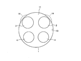
- FIG. 2 is a plan layout view of the four-cycle internal combustion engine of the present embodiment. It is sectional drawing explaining the effect of the 4-cycle internal combustion engine of a present Example. It is a graph which shows the effect which acts on the moment and vibration force in the 4-cycle internal combustion engine of a present Example. It is sectional drawing which shows the 4-cycle internal combustion engine compared in the graph of FIG. It is a side view which shows the shape of the valve umbrella of the exhaust valve used for a present Example. It is a side view which shows the example of a shape of the recess of the cylinder top part in a present Example.
- the exhaust valve and the intake valve may be enlarged in order to increase the supply / exhaust speed or increase the supply / exhaust amount while maintaining the cylinder size.
- the exhaust valve and air supply valve due to the large size of the exhaust valve and air supply valve, if the outer periphery of the valve umbrella is close to the inner wall of the combustion chamber of the cylinder part, the valve seat seat surface will be biased while the engine is running. Damage was found to occur.
- the damage that occurs in this way is caused by damage to the outer peripheral side of the combustion chamber, especially on the valve seat surface of the exhaust valve, and it is necessary to increase the frequency of replacing the valve seat of the exhaust valve, resulting in a heavy maintenance burden.
- the reason why the valve seat against which the exhaust valve hits rather than the supply valve is more likely to be damaged is that high-pressure and high-temperature combustion gas after explosion flows through the exhaust valve.
- the portion of the seat surface of the valve seat close to the inner wall of the cylinder is easily damaged because the valve umbrella swings in this direction.
- the present invention provides a method for eliminating problems caused by increasing the size of the intake valve and the exhaust valve with respect to the dimensions of the cylinder, for example, in order to improve the performance of the internal combustion engine.
- FIG. 1 is a partial cross-sectional view of an exhaust valve structure according to one embodiment of the present invention.
- FIG. 2 is a plan view illustrating a positional relationship among the cylinder, the air supply valve, the exhaust valve, and the recess (dent) in the present embodiment.
- the exhaust valve structure of the present embodiment is applied to a four-cycle internal combustion engine such as a gas engine or a diesel engine provided with the exhaust valve 2 and the air supply valve 4. It is characterized by a shape and a recess (dent) 14 provided at the upper end of the cylinder inner wall 13, and other parts are the same as usual.
- the exhaust valve 2 is reciprocated by the action of a tappet and a valve spring (not shown) with the valve rod 21 guided by the valve guide 35.
- the seat surface 24 formed on the peripheral edge of the upper surface of the valve umbrella 22 comes into contact with the seat surface 32 of the valve seat 31 to close the combustion gas flow.
- the exhaust valve 2 is closed during the air supply stroke, the compression stroke, and the combustion stroke.
- the exhaust stroke when the valve rod 21 is pushed downward in FIG. 1 and the exhaust valve 2 moves away from the valve seat 31, the high-temperature and high-pressure combustion gas in the combustion chamber 11 is exhausted to the outside through the exhaust path 12.
- the exhaust path 12 may be connected to an exhaust port of another exhaust valve.
- the exhaust valve 2 rotates the valve rod 21 little by little during reciprocation during operation to equalize the wear of the seat surface 24, prevent damage, and increase the replacement period of the exhaust valve 2. .
- the exhaust valve structure of this embodiment includes the exhaust valve 2 that reciprocates near the cylinder wall 13 of the internal combustion engine.
- the upper end of the cylinder wall 13 is provided with a recess (recess) 14 in a region where the valve head 22 of the exhaust valve 2 reciprocates.
- the outer peripheral edge 25 of the valve umbrella 22 reciprocates without interfering with the cylinder wall 13, and a sufficiently large gap through which combustion gas passes is formed between the outside of the side edge 26 and the wall of the recess 14. ing.
- the combustion chamber side inlet of the gas flow path formed in the gap between the side edge 26 and the wall of the recess 14 is a large opening that does not generate choke.
- the recess 14 is configured so that the pressure of the high-pressure combustion gas acts also on the side of the valve umbrella 22 that is close to the cylinder wall 13 of the exhaust valve 2 in the exhaust stroke. The flow is prevented from forming a choke portion upstream of the outer peripheral edge 25 of the valve umbrella 22.
- the head 23 of the valve umbrella 22 of the exhaust valve 2 has a conical side edge 26, and the cross section thereof is formed so as to become narrower from the outer peripheral edge 25 of the valve umbrella 22 toward the top of the head. .
- a top surface 27 perpendicular to the axis of the valve stem 21 is formed on the top of the head.
- the cylinder 1 has a relatively large recess 14 on the wall (cylinder wall 13) relative to the bottleneck 41 (see FIG. 3A described later).
- the flow path of the combustion gas at the wall has a sufficient flow path width, the pressure drop due to flowing along the side edge 26 portion is small, and the choke portion where the large pressure drop occurs is the outer peripheral edge 25 of the valve umbrella. It will be formed in the vicinity of.
- the pressure of the high-pressure combustion gas in the combustion chamber 11 also acts on the side edge 26 near the wall of the valve umbrella 22. Therefore, the pressure acting on the side edge 26 of the valve umbrella 22 is equalized over the entire circumference, and the moment for pressing the exhaust valve 2 toward the cylinder wall 13 does not increase.
- the taper angle of the side edge 26 is set in the range of 10 ° to 80 °, particularly 20 ° to 40 °.
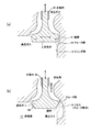
- FIG. 3 is a drawing for explaining the effect of the exhaust valve structure of this embodiment as compared with the prior art.
- FIG. 3A is a cross-sectional view showing an exhaust valve structure in the prior art
- FIG. 3B is a cross-sectional view showing an exhaust valve structure according to this embodiment.
- 3 (a) and 3 (b) the exhaust valve 2 moves downward from the closed position to an open state, and the combustion gas in the combustion chamber 11 flows out from between the exhaust valve 2 and the valve seat into the exhaust passage. Yes.
- the wall (cylinder wall 13) of the passage through which the exhaust valve 2 reciprocates and the valve umbrella side edge or the valve umbrella outer periphery form a choke portion 42.
- the combustion gas flows while maintaining the pressure in the combustion chamber 11 to the vicinity of the choke portion 42, passes through the choke portion 42, is greatly decompressed, and flows down to the exhaust path.
- the leaflet side edge is formed in a cylindrical surface shape, and the leaflet side edge is opposed to the cylinder wall 13 between the cylinder wall 13 and the leaflet side edge.
- a choke portion 42 is formed at the combustion chamber 11 side end of the soot 41 when combustion gas flows out of the soot 41.
- the high pressure in the combustion chamber 11 does not act on the valve umbrella side edge downstream of the choke portion 42, and the pressure that has decreased through the choke portion 42 acts.
- regions other than the region where the valve umbrella side edge faces the cylinder wall 13 there is no wall facing the valve umbrella side edge, and most of the valve umbrella side edge is exposed to high-pressure combustion gas.
- the present inventors have confirmed this phenomenon by estimating the pressure distribution around the exhaust valve by using CFD (Computational Fluid Dynamics).
- the top side edge 26 of the valve head of the exhaust valve 2 is thinned so that the cross section of the top side edge 26 is outside the valve head. Formed so that it is the thickest at the peripheral edge 25 and becomes thinner from the outer peripheral edge 25 toward the top of the head, and a recess (dent) 14 is formed in the upper edge of the cylinder wall 13 in the region where the valve umbrella side edge 26 faces. It is.
- the gap formed between the wall of the formed recess 14 and the valve umbrella side edge 26 is configured such that no choke is formed at the end portion on the combustion chamber 11 side.
- FIG. 4 is a graph showing the effect of the exhaust valve structure of this embodiment on the moment and vibration force
- FIG. 5 is a schematic diagram showing the structure from which the effect of FIG. 4 is derived.
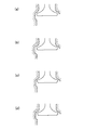
- the graph of FIG. 4 shows the conventional structure (FIG. 5A), the structure in which the recess is formed (FIG. 5B), and the structure in which the shape of the exhaust valve umbrella is tapered (FIG. 5).
- FIG. 5C shows the change in moment or vibration force with respect to the crank angle for a structure (FIG. 5D) that combines recess formation and valve shape change.
- the recess in FIG. 5B is formed larger than the recess in FIG.
- Fig. 4 (a) shows how the moment of the exhaust valve that works in the direction in which the valve head and the cylinder wall are closest changes according to the crank angle.
- the moment increases in the exhaust stroke.
- the moment is reduced by changing the shape of the valve head compared to the conventional structure, the moment is further reduced by combining the change of the valve head shape and the formation of the recess, It can also be seen that using a large recess greatly reduces the moment.
- FIG. 4 (b) shows a state in which the excitation force of the exhaust valve that works in the direction in which the valve umbrella and the cylinder wall are closest to each other changes according to the crank angle together with the change in the valve lift.
- the excitation force in the above direction increases in the exhaust stroke.
- the vibration force is reduced by changing the shape of the valve head compared to the conventional structure, and the vibration force is further increased by combining the valve shape change and the formation of the recess. It can be seen that the vibration force decreases significantly when a large recess is used.
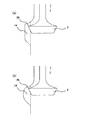
- FIG. 6 is a side view showing an example of the shape of the valve umbrella of the exhaust valve used in this embodiment.
- the exhaust valve used in the present embodiment is formed so that the cross section of the side of the top of the head is thickest at the outer peripheral edge 25 of the valve umbrella and becomes thinner from the outer peripheral edge 25 toward the top of the head.
- 6A is a truncated cone having a taper angle of ⁇ .
- 6B has a conical shape with a taper angle ⁇ and a vertex at the top of the valve head.
- the tapered angle ⁇ of both the truncated cone and the conical umbrella is preferably between 10 ° and 80 °, in particular between 20 ° and 40 °.
- the taper angle ⁇ is larger than the above-mentioned range, the periphery of the valve umbrella becomes thin, the strength is insufficient and the combustion gas is distorted at a high temperature, or the pressure difference applied to the valve umbrella is bent, and the seat part contacts. May become defective.
- the taper angle ⁇ is smaller than the above-described range, the widening effect of the bottleneck cannot be sufficiently obtained.
- FIG. 7 is a side view showing an example of the shape of the recess at the top of the combustion chamber in the present embodiment.
- the recess 14 shown in FIG. 7 (a) has a cylindrical surface shape in which the wall surface facing the outer edge of the valve umbrella is parallel to the valve shaft, and becomes shallower in a tapered portion in the lower part where the exhaust valve 2 does not reach. Combined with the wall 13.
- the taper angle of the lower part of the recess 14 is smaller than the taper angle ⁇ of the side face on the top side of the exhaust valve, the combustion gas passage between the wall of the recess 14 and the side edge of the valve head becomes a passage width as it goes downward. Will spread.
- the recess shape shown in FIG. 7B has a curved wall surface facing the outer edge of the valve umbrella. In the recess 14 having a curved surface, the distance between the wall of the recess 14 and the outer peripheral edge 25 of the valve umbrella is sufficiently large, so that the vibration force and moment are sufficiently weak.
- valve umbrella becomes larger and the outer peripheral edge of the valve umbrella exceeds the inner wall of the cylinder, it is necessary to pull out the valve seat part in the direction of the valve shaft for maintenance.
- the cylinder wall is provided with a recess having a size that allows the valve seat to be pulled out without hitting the outer edge of the valve umbrella. Even in the recess for pulling out the valve seat part, a narrow gap is formed between the wall of the recess and the side edge of the valve umbrella, thereby obstructing the flow of combustion gas.
- the upper end of the cylinder wall is provided with a recess that allows a sufficient clearance for the combustion gas to pass outside the outer periphery of the valve umbrella, It goes without saying that the same effect can be obtained by forming the head portion of the valve head so that its cross section becomes narrower as it approaches the top of the head than the outer periphery of the valve head.
- a sufficiently large exhaust valve and an intake valve are applied to a four-cycle internal combustion engine to increase the exhaust amount of a diesel engine or a gas engine, or to shorten the exhaust time. , The engine performance can be improved.
Landscapes
- Engineering & Computer Science (AREA)
- Mechanical Engineering (AREA)
- General Engineering & Computer Science (AREA)
- Chemical & Material Sciences (AREA)
- Combustion & Propulsion (AREA)
- Physics & Mathematics (AREA)
- Geometry (AREA)
- Cylinder Crankcases Of Internal Combustion Engines (AREA)
Abstract
排気弁2の弁傘22の側縁26との間にチョークが発生しないように内壁を後退させて形成したリセス(凹み)14を内壁の上縁部に設けたシリンダ部1と、弁傘22の頭部26の断面が弁傘22の外周縁25より頭頂に近づくにつれて細くなる形状に形成された排気弁2を備える。
Description
本発明は、排気弁における首振り運動を低減する4ストローク内燃機関に関し、特にシリンダに対して大型の排気弁を使う場合において、排気弁の首振り運動による弁座の傷害を軽減するようにした4ストローク内燃機関およびこれに適用する排気弁に関する。
内燃機関の性能向上を目的として燃焼室の容積を増大させる設計を行うと、従来最適に調整できていた火炎伝播が遅くなりすぎてノッキングが発生しやすくなったり、圧縮比が小さくなって性能が低下したりする場合がある。このような問題を回避するため、燃焼室のサイズを変える代わりに、給気弁と排気弁のサイズを大きくして給排気時間を短縮することにより、内燃機関の性能向上を図る方法もある。
しかし、シリンダ径に対して排気弁の径を大きくすると、弁座のシール部の一部が摩耗する現象が生じる場合があり、部品交換の頻度が増大して保全コストを増加させる問題があった。本願発明者等が弁棒の振動変位測定やCFD解析(Computational Fluid Dynamics)などを利用して検討した結果から、この偏摩耗は、排気行程において壁に向かう方向の力が排気弁に掛かって排気弁が首振り運動を行うことが原因であることが分かった。
すなわち、排気弁がシリンダ径に対して大きいため、排気弁の弁傘の外縁とシリンダ内壁の間隙が狭くなって隘路が形成される。排気行程において高圧燃焼ガスがシリンダから排出されるときに、この隘路のシリンダ側端点に絞り部が形成される。燃焼ガスは絞り部を通過すると低圧になるため、隘路に面する弁傘側部には、より低圧のガス圧力が作用する。一方、隘路以外の弁傘側部には、高圧燃焼ガスの圧力が働く。それ故、排気弁には、シリンダ壁に向いたモーメントが発生することになる。
排気弁の弁傘は、この力により壁側に振れる。あるいは、この力と弁棒の剛性による抗力により弁体が振動するようになる。こうして、弁体は、弁傘とシリンダ内壁の間隔がほぼ最小になる方向に振れる。このため、排気弁が弁座に接触する位置がシリンダ壁側に偏ることが多く、弁座におけるシール部の摩耗が偏在する結果となる、と推察される。
本出願人は、特許文献を探査したが、内燃機関の排気弁に生起する首振り現象およびこれに対する対策に関する適当な文献を発見することができなかった。なお、特許文献1には、排気弁と給気弁を備えるディーゼルエンジンにおいて、排気弁と給気弁の弁径および弁形状を同じに形成して互換性を持たせることにより、コストダウンを図る発明が開示されている。特許文献1には、給気弁や排気弁の頭部面を半球面状に形成することによって、弁強度を高めると共に、燃焼時の給気排気をシリンダ内で頭部面に沿わせて攪乱ないし撹拌させることが記載されている。しかし、燃焼工程における半球面状の頭部面に沿った気流は、半球の頂部を横切る方向に流れる三次元的な気流となって燃料の混合性および燃焼性を高めるもので、排気行程における排気弁と弁座の開口に向けて流れる気流に関係するものではない。それ故、弁体の首振りないし振動に関わるものでもない。
そこで、本発明が解決しようとする課題は、排気弁を備えたディーゼル機関またはガス機関のシリンダ部品において、排気弁の弁傘外周部がシリンダ内壁に近い領域で弁傘側部に掛かるガス圧差により生じるモーメントを原因とする弁体の首振り運動を抑制して、異常な摩耗を防止し弁座や弁体の寿命を延ばした4サイクル内燃機関およびこれに適用する排気弁を提供することである。
上記課題を解決するため、本発明の4サイクル内燃機関は、排気弁の弁傘の側縁との間にチョークが発生しないように内壁を後退させて形成したリセス(凹み)を内壁の上縁部に設けたシリンダと、弁傘の頭部の断面が弁傘の外周縁より頭頂に近づくにつれて細くなる形状に形成された排気弁を備えることを特徴とする。
内燃機関の性能向上を目的として給排気性能を向上するため、シリンダ寸法を変更しないまま給気弁や排気弁の寸法を大きくすると、排気弁の弁傘側面がシリンダ内壁に近づき、弁傘外縁の側面とシリンダ内壁の間に隘路が形成される。この隘路をシリンダ内部の高温高圧ガスが流れるときに隘路の入口付近にチョーク部を形成する。このチョーク部のシリンダ側は、シリンダ内部の高温燃焼ガスの高圧状態になっていても、チョーク部を通過した後のシリンダ内壁に対向する弁傘側面には、シリンダ内部の圧力より低い圧力しか掛からない。一方、シリンダ壁側の隘路以外の弁傘側面は、ほぼシリンダ内に露出しているので、高圧燃焼ガスの圧力が働く。このため、排気弁には、シリンダ壁に向かう力が作用して首振り現象が発生することになる。
これに対して、本発明の4サイクル内燃機関では、排気弁の側面とシリンダ壁までの距離が大きくなって隘路およびチョーク部が解消している。それ故、シリンダ壁面に対向する排気弁の弁傘側面の大部分に高圧ガスが作用するようになって弁傘を壁に向かって押し付ける力が弱くなり、排気弁に首振り運動もしくは振動を生起させにくくなる。こうして、排気弁の首振り運動等に伴う弁案内の摩耗が減少し、また弁座の弁シート面における摩耗が減少し、エンジン部品の寿命を延ばすことができた。なお、シリンダ内壁頂部のリセスは、弁傘の側面との間に形成されるガスの流路が弁傘の外周縁からシリンダの内部側に向けて拡幅するように形成されることが好ましい。また、排気弁の弁傘は、10°から80°、特に20°から40°、のテーパで形成されることが好ましい。
また、上記課題を解決するため、本発明の排気弁は、燃焼室の内壁と排気弁の弁傘側縁との間が近い内燃機関に使用される排気弁であって、燃焼室の内壁と排気弁の弁傘側縁との間にチョークが発生しないように、弁傘の頭部の断面が弁傘の外周縁より頭頂に近づくにつれて細くなる形状に形成されることを特徴とする。本発明の排気弁は、シリンダの内壁上縁部に設けた排気弁の弁傘の側縁との間にチョークが発生しないような通路を形成するリセスと協働して、排気弁の弁案内の摩耗を減少させ、弁座の弁シート面における摩耗を減少させ、エンジン部品の寿命を延ばすことができる。
4サイクル内燃機関において、シリンダのサイズを維持したまま給排気速度を高めたり給排気量を増大させたりするために、排気弁と給気弁を大型化する場合がある。しかし、排気弁と給気弁の大型化で、これら弁の弁傘外周縁がシリンダ部の燃焼室の内壁と近いと、機関を稼働させているうちに、弁座シート面の偏った位置に損傷が発生することが分かった。
こうして発生する損傷は、特に排気弁の弁座シート面において、燃焼室外周側の部分が偏って傷付くもので、排気弁の弁座を取り換える頻度を増やす必要があり、保全上の負担が大きくなる。なお、給気弁ではなく、排気弁が当たる弁座の方が損傷を受け易いのは、排気弁には爆発後の高圧高温の燃焼ガスが流れるためである。また、弁座のシート面のうちシリンダ内壁に近い部分が損傷を受けやすいのは、弁傘がこの方向に振れるためである。
本発明は、たとえば内燃機関の性能向上のために、シリンダの寸法に対して給気弁と排気弁を大型化することにより生じた不具合を解消する方法を提供するものである。従来、このような手段をもって内燃機関の性能向上を図る場合に、特有な不具合が発生する事実もこのような不具合の解消方法も、よくは知られていなかった。
以下、図面に基づき、実施例を用いて本発明の排気弁構造について詳細に説明する。図1は、本発明の1実施例に係る排気弁構造の一部断面図である。また、図2は、本実施例におけるシリンダと給気弁と排気弁とリセス(凹み)との位置関係を説明する平面配置図である。本実施例の排気弁構造は、排気弁2と給気弁4を備えるガス機関やディーゼル機関などの4サイクル内燃機関に適用するもので、大型化した排気弁2の弁傘22の頭部における形状と、シリンダ内壁13の上端部に設けられたリセス(凹み)14に特徴があり、その他の部分は通常のものと変わりはない。
排気弁2は、弁棒21が弁案内35で案内されて、図外のタペットとバルブスプリングの作用で往復運動する。弁傘22の上面周縁部に形成されるシート面24が弁座31のシート面32に接することにより燃焼ガス流を閉止する。排気弁2は、給気行程、圧縮行程、燃焼行程の間は閉止している。他方、排気行程では、弁棒21が図1の下方に押されて排気弁2が弁座31から離れると、燃焼室11内の高温高圧の燃焼ガスが排気路12を介して外部に排気される。排気弁2が複数ある時は、排気路12が別の排気弁の排気口と繋がっていてもよい。なお、排気弁2は、運転中に弁棒21を往復動と共に僅かずつ回転させて、シート面24の摩耗を均等化させ、損傷を防ぎ、排気弁2の交換周期が長くなるようにしている。
本実施例の排気弁構造では、内燃機関のシリンダ壁13の近くで往復運動する排気弁2を備えている。シリンダ壁13の上端部は、そこの排気弁2の弁傘22が往復する領域にリセス(凹み)14を備えている。このリセス14により、弁傘22の外周縁25がシリンダ壁13と干渉せず往復し、かつ、側縁26の外側とリセス14の壁との間に燃焼ガスが通る十分な大きな隙間が形成されている。側縁26とリセス14の壁の間の隙間に形成されるガス流路の燃焼室側入口は、チョークが発生しない程度の大きな開口とされる。本実施例におけるリセス14は、特に、排気行程において、排気弁2のシリンダ壁13に近い部分にあたる弁傘22側部にも高圧の燃焼ガスの圧力を作用させるために、排気弁2における燃焼ガス流が、弁傘22の外周縁25より上流側でチョーク部を形成しないようにされている。
また、排気弁2の弁傘22の頭部23は、円錐状の側縁26を有しており、その断面が弁傘22の外周縁25より頭頂に近づくにつれて細くなるように形成されている。また、頭頂には、弁棒21の軸に対して垂直な頭頂面27が形成されている。
本実施例の排気弁構造では、シリンダ1の壁(シリンダ壁13)際に隘路41(後述する図3(a)参照)に対して相対的に大きなリセス14を有している。これにより、壁際における燃焼ガスの流路が十分な流路幅を有し、側縁26部分に沿って流れることによる圧力降下は小さく、また大きな圧力降下が生じるチョーク部が弁傘の外周縁25の近傍に形成されることとなる。このため、弁傘22の壁際の側縁26にも燃焼室11における高圧の燃焼ガスの圧力が作用する。したがって、弁傘22の側縁26に働く圧力は全周にわたって均等化し、排気弁2をシリンダ壁13の方向に押し付けるモーメントは強くならない。
なお、側縁26のテーパ角度が大きすぎると弁傘22の剛性が不足してシート面24が変形し易くなり、テーパ角度が小さすぎれば燃焼室における圧力が弁傘22の側縁26に及びにくくなる。したがって、側縁26のテーパ角度は、10°から80°、特に20°から40°の範囲に設定されている。なお、図示しないが、燃焼室11の天井における中心軸上に、副燃焼室が設けられたガス機関についても、本実施例の排気弁構造が適用できることはいうまでもない。
図3は、従来技術と比較して本実施例の排気弁構造の効果を説明する図面である。図3(a)は、従来技術における排気弁構造を示す断面図、図3(b)は、本実施例に係る排気弁構造を示す断面図である。図3(a)及び(b)において、排気弁2は閉位置から下方に移動して開状態になり、燃焼室11内の燃焼ガスは排気弁2と弁座の間から排気路に流れ出している。排気弁2が往復運動する通路の壁(シリンダ壁13)と弁傘側縁又は弁傘外周縁とがチョーク部42を形成する。燃焼ガスは、チョーク部42近傍まで燃焼室11の圧力を保持した状態で流れてきて、チョーク部42を通過して大きく減圧し、排気路に流れ下る。
図3(a)に示す従来の排気弁構造では、弁傘側縁が円柱面状に形成され、弁傘側縁がシリンダ壁13に対向する領域でシリンダ壁13と弁傘側縁との間に隘路41が形成され、燃焼ガスが隘路41から流出するときに隘路41の燃焼室11側端にチョーク部42が形成される。チョーク部42より下流の弁傘側縁には、燃焼室11内の高圧が作用せず、チョーク部42を通過して低下した圧力が作用することになる。一方、弁傘側縁がシリンダ壁13に対向する領域以外の領域では、弁傘側縁に面する壁がなく、弁傘側縁のほとんどが高圧の燃焼ガスに晒される。本願発明者等は、CFD(Computational Fluid Dynamics)を用いて、排気弁周りの圧力分布を推定することにより、この現象を確認した。
このように、弁傘側縁に働く燃焼室11の中心側からシリンダ壁13に向かう大きな圧力とシリンダ壁13側から中心に向けて働く小さな圧力の間に圧力差があるため、排気弁2にはシリンダ壁13に向かう方向にモーメントが発生し、排気弁2はシリンダ壁13に向かって振れる。排気弁2がこの姿勢で弁座に当接すると、弁座のシート面のシリンダ壁13に近い方の部分に排気弁2が強く当たり、他の部分より摩耗が進むことになる。このため、弁座部分の交換周期が短くなって、保全コストが増大する。なお、本願発明者等は、試験用エンジンの排気路にのぞき窓を設置し、レーザ変位計を使って排気弁の弁棒の動きを観察して、排気行程で弁棒の首振り運動が発生することを確認した。
一方、図3(b)に示した本実施例の排気弁構造は、排気弁2の弁傘の、頭頂側側縁26を減肉して、頭頂側側縁26の断面が弁傘の外周縁25で最も太く外周縁25から頭頂に近づくにつれて細くなるように形成し、かつ、シリンダ壁13の上縁部において、弁傘側縁26が対向する領域にリセス(凹み)14を形成したものである。形成されたリセス14の壁と弁傘側縁26の間に形成される間隙は、燃焼室11側の端部にチョークが形成されないようになっている。
したがって、燃焼ガス排気中にも、リセス14に対向する側の弁傘側縁26に燃焼室11側の高圧ガスが作用するので、弁傘側縁26に働く圧力の偏差に基づいたモーメントが小さく、排気弁2の振れ運動が減少する。このように、本実施例の排気弁構造を持つことにより、弁座シート面の偏在的な摩耗を防止し、弁座の寿命を延ばすことができる。また、弁棒21の振動が減少するので弁案内35の損傷も防止することができる。
図4は本実施例の排気弁構造がモーメントおよび起振力に及ぼす効果を示すグラフ、図5は図4の効果を導き出した構造を示す模式図である。図4のグラフは、図5に示した、従来構造(図5(a))、リセスを形成した構造(図5(b))、排気弁弁傘の形状をテーパ状にした構造(図5(c))、リセス形成と弁傘形状変更を組み合わせた構造(図5(d))について、クランク角度に対するモーメントまたは起振力の変化を示している。なお、図に見るように、図5(b)のリセスは図5(d)のリセスより大きく形成されている。
図4(a)は、弁傘とシリンダ壁が最も近い方向に働く排気弁のモーメントがクランク角度にしたがって変化する様子を示す。図4(a)のグラフから分かるように、排気行程の部分にモーメントが大きくなる領域が存在している。また、図4(a)のグラフから、従来構造と比較して弁傘形状を変更することによりモーメントが減少すること、弁傘形状変更とリセスの形成を合わせることによりさらにモーメントが減少すること、また、大きなリセスを使うとモーメントが大幅に減少することが分かる。
図4(b)は、弁傘とシリンダ壁が最も近づく方向に働く排気弁の起振力がクランク角度にしたがって変化する様子をバルブリフトの変化と共に示す。図4(b)グラフからわかるように、排気行程で上記方向の起振力が大きくなる。また、図4(b)のグラフから、従来構造と比較して弁傘形状を変更することにより起振力が減少すること、弁傘形状変更とリセスの形成を合わせることによりさらに起振力が減少すること、また、大きなリセスを使うと起振力が大幅に減少することが分かる。
上に詳しく説明した通り、排気弁2の弁傘22の形状変更と、シリンダ部1の上端部に形成されるリセス14が、排気弁2の首振りあるいは振動を効果的に抑制することが分かる。そこで、本願発明者等は、図1に示すような排気弁構造を発明するに至ったものである。
図6は、本実施例に用いる排気弁の弁傘の形状例を示す側面図である。本実施例に用いる排気弁は、頭頂側側部の断面が弁傘の外周縁25で最も太く外周縁25から頭頂に近づくにつれて細くなるように形成されている。図6(a)に示す弁傘形状は、テーパ角度がθの円錐台である。また、図6(b)に示す弁傘形状は、テーパ角度がθの、弁傘頭頂に頂点を持つ円錐の形状をしている。円錐台の弁傘も円錐の弁傘も、テーパ角度θは、10°から80°の間、特に20°から40°の間にあることが好ましい。テーパ角度θが上述する範囲より大きくなると、弁傘の周縁部が薄くなり、強度が不足して燃焼ガスの高温でゆがんだり、また弁傘に掛かる圧力差で撓んだりしてシート部の接触が不良化する場合がある。また、テーパ角度θが上述する範囲より小さい場合は、隘路の拡幅の効果を十分に得ることができない。
図7は、本実施例における燃焼室頂部のリセスの形状例を示す側面図である。図7(a)に示すリセス14は、弁傘外縁に対向する壁面が弁軸に平行な円筒面形状を有し、排気弁2が到達しない下方部分でテーパ状に浅くなって燃焼室のシリンダ壁13と合わさっている。なお、リセス14下方部分のテーパ角度が、排気弁の弁傘頭頂側側面のテーパ角度θより小さい場合は、リセス14の壁と弁傘側縁の間の燃焼ガス通路は下方に行くにつれて通路幅が広がるようになる。これにより、リセス部分の弁傘側縁に燃焼ガスの高圧が作用するので、圧力差に起因する起振力やモーメントが十分弱くなる利点がある。図7(b)に示すリセス形状は、弁傘外縁に対向する壁面が曲面になっている。曲面をしたリセス14では、リセス14の壁と弁傘の外周縁25との間の距離が十分大きいので、起振力やモーメントが十分弱い。
なお、さらに、弁傘が大きくなって、弁傘の外周縁がシリンダ内壁を超えるような場合には、保全のために弁座部品を弁軸の方向に引き抜けるようにする必要から、シリンダ内壁に弁傘外縁が当たらず弁座を引き出すことができる程度の大きさを持つリセスがシリンダ壁に設けられる。弁座部品を引き抜くためのリセスにおいても、リセスの壁と弁傘側縁との間に狭い隙間ができて、燃焼ガスの流れを阻害する。したがって、このような場合においても、本発明の技術的思想に基づき、シリンダ壁の上端部に、弁傘の外周縁の外側に燃焼ガスが通る十分な隙間を持たせるリセスを備え、排気弁の弁傘頭部を断面が弁傘外周縁より頭頂に近づくにつれて細くなる形状に形成することにより、同様の効果が得られることはいうまでもない。
本発明の排気弁構造を使用することにより、十分大きな排気弁および給気弁を4サイクル内燃機関に適用して、ディーゼル機関やガス機関などの排気量を増大させ、あるいは排気時間を短縮して、機関の性能を向上させることができる。
1 シリンダ部
11 燃焼室
12 排気路
13 シリンダ内壁
14,14A リセス(凹み)
2 排気弁
21 弁棒
22 弁傘
23 頭部
24 排気弁シート部
25 外周縁
26 側縁
27 頭頂面
31 弁座
32 弁座シート部
35 弁案内
4 給気弁
41 隘路
42 チョーク部
11 燃焼室
12 排気路
13 シリンダ内壁
14,14A リセス(凹み)
2 排気弁
21 弁棒
22 弁傘
23 頭部
24 排気弁シート部
25 外周縁
26 側縁
27 頭頂面
31 弁座
32 弁座シート部
35 弁案内
4 給気弁
41 隘路
42 チョーク部
Claims (5)
- 排気弁の弁傘の側縁との間にチョークが発生しないように内壁を後退させて形成したリセスを内壁の上縁部に設けたシリンダ部と、前記弁傘の頭部の断面が該弁傘の外周縁より頭頂に近づくにつれて細くなるように形成された排気弁を備えた4サイクル内燃機関。
- 前記シリンダ部のリセスが、前記弁傘の側面と該リセスの壁との間に形成されるガスの流路が前記排気弁の開閉する領域において前記弁傘の外周縁から前記シリンダ部の内部側に向けて拡幅するように形成される、請求項1記載の4サイクル内燃機関。
- 前記弁傘の形状は、20°から40°の範囲内のテーパで形成されることを特徴とする、請求項1または2記載の4サイクル内燃機関。
- 燃焼室の内壁と排気弁の弁傘側縁との間が近い内燃機関に使用される排気弁であって、燃焼室の内壁と排気弁の弁傘側縁との間にチョークが発生しないように、弁傘の頭部の断面が該弁傘の外周縁より頭頂に近づくにつれて細くなる形状に形成された排気弁。
- 前記弁傘の形状は、20°から40°の範囲内のテーパで形成されることを特徴とする、請求項4記載の排気弁。
Priority Applications (2)
| Application Number | Priority Date | Filing Date | Title |
|---|---|---|---|
| US13/514,307 US20120266840A1 (en) | 2009-12-21 | 2010-12-17 | Four-stroke internal combustion engine and exhaust valve |
| EP10838926.3A EP2518285B1 (en) | 2009-12-21 | 2010-12-17 | Four-stroke internal combustion engine and exhaust valve |
Applications Claiming Priority (2)
| Application Number | Priority Date | Filing Date | Title |
|---|---|---|---|
| JP2009-289503 | 2009-12-21 | ||
| JP2009289503A JP5036799B2 (ja) | 2009-12-21 | 2009-12-21 | 4ストローク内燃機関 |
Publications (1)
| Publication Number | Publication Date |
|---|---|
| WO2011077686A1 true WO2011077686A1 (ja) | 2011-06-30 |
Family
ID=44195240
Family Applications (1)
| Application Number | Title | Priority Date | Filing Date |
|---|---|---|---|
| PCT/JP2010/007343 Ceased WO2011077686A1 (ja) | 2009-12-21 | 2010-12-17 | 4ストローク内燃機関と排気弁 |
Country Status (4)
| Country | Link |
|---|---|
| US (1) | US20120266840A1 (ja) |
| EP (1) | EP2518285B1 (ja) |
| JP (1) | JP5036799B2 (ja) |
| WO (1) | WO2011077686A1 (ja) |
Cited By (2)
| Publication number | Priority date | Publication date | Assignee | Title |
|---|---|---|---|---|
| US9080531B2 (en) | 2011-03-31 | 2015-07-14 | Mitsubishi Heavy Industries, Ltd. | Cylinder structure for internal combustion engine |
| CN106194445A (zh) * | 2016-08-16 | 2016-12-07 | 上海交通大学 | 用于低速柴油机的排气阀自旋机构 |
Families Citing this family (13)
| Publication number | Priority date | Publication date | Assignee | Title |
|---|---|---|---|---|
| US20160076480A1 (en) * | 2012-02-04 | 2016-03-17 | David Endrigo | Valve seats for cylinder heads in aircraft engines |
| NO336985B1 (no) * | 2014-06-03 | 2015-12-14 | Bergen Engines As | Innløpsventil for en motor |
| US20160333751A1 (en) * | 2015-05-07 | 2016-11-17 | Frank J. Ardezzone | Engine Insert and Process for Installing |
| CN105298676A (zh) * | 2015-11-02 | 2016-02-03 | 重庆金花玻璃钢有限公司 | 带密封圈易修复型发动机缸盖 |
| CN105240145A (zh) * | 2015-11-02 | 2016-01-13 | 重庆金花玻璃钢有限公司 | 耐磨型发动机缸盖 |
| CN105240147A (zh) * | 2015-11-02 | 2016-01-13 | 重庆金花玻璃钢有限公司 | 能改气门部冷却、热量损失和密封性能的发动机缸盖 |
| CN105240138A (zh) * | 2015-11-02 | 2016-01-13 | 重庆金花玻璃钢有限公司 | 能改气门部冷却和热量损失的发动机缸盖 |
| CN105240144A (zh) * | 2015-11-02 | 2016-01-13 | 重庆金花玻璃钢有限公司 | 能改善涡流比、密封性能和气门部冷却的发动机缸盖 |
| JP6638618B2 (ja) * | 2016-10-19 | 2020-01-29 | トヨタ自動車株式会社 | エンジンの製造方法 |
| DE102017119887A1 (de) | 2017-08-30 | 2019-02-28 | Man Truck & Bus Ag | Ventil für einen Verbrennungsmotor |
| US11060425B2 (en) * | 2019-03-13 | 2021-07-13 | Caterpillar Inc. | Valve seat insert for engine head having venturi flow crowns and seating surface profiled for limiting valve recession |
| US11125123B1 (en) * | 2020-03-17 | 2021-09-21 | Caterpillar Inc. | Valve seat insert with soft landing insert design with contoured radii |
| US11125122B1 (en) * | 2020-03-17 | 2021-09-21 | Caterpillar Inc. | Valve seat insert with soft landing insert design with contoured radii |
Citations (2)
| Publication number | Priority date | Publication date | Assignee | Title |
|---|---|---|---|---|
| JP2003307106A (ja) | 2002-04-15 | 2003-10-31 | Iseki & Co Ltd | ディーゼルエンジンの吸排気弁 |
| JP3527889B2 (ja) * | 2000-12-21 | 2004-05-17 | ダイハツディーゼル株式会社 | プロテクトリング |
Family Cites Families (15)
| Publication number | Priority date | Publication date | Assignee | Title |
|---|---|---|---|---|
| GB223213A (en) * | 1923-10-13 | 1925-04-09 | Ettore Bugatti | Improvements in light valves for internal combustion engines |
| US2270990A (en) * | 1940-01-25 | 1942-01-27 | Reconstruction Finance Corp | Engine |
| US2866445A (en) * | 1956-12-19 | 1958-12-30 | Justin W Macklin | Piston and combustion chamber and injection nozzle mounting construction for compression ignition engine |
| US3038455A (en) * | 1959-06-12 | 1962-06-12 | Slobodan M Dobrosavljevic | Internal combustion engine |
| US3086506A (en) * | 1960-07-19 | 1963-04-23 | Dobrosavljevic Sloboda Milivoy | Air-cooled two-stroke diesel engine |
| US3728994A (en) * | 1970-08-18 | 1973-04-24 | Teledyne Ind | Exhaust port structure |
| JPS58151306U (ja) * | 1982-04-05 | 1983-10-11 | 日産自動車株式会社 | 内燃機関の吸排気バルブ |
| JPS63164523U (ja) * | 1987-04-15 | 1988-10-26 | ||
| US5230310A (en) * | 1991-03-29 | 1993-07-27 | Mazda Motor Corporation | Combustion chamber of internal combustion engine |
| GB9118944D0 (en) * | 1991-09-05 | 1991-10-23 | Bullivant Nicholas T | Engine rotary valves |
| DE19602720B4 (de) * | 1996-01-26 | 2008-03-27 | Audi Ag | Hubventil |
| US5709183A (en) * | 1996-12-23 | 1998-01-20 | Chrysler Corporation | Shroud and combustion chamber for an internal combustion engine |
| US5823158A (en) * | 1997-03-04 | 1998-10-20 | Trw Inc. | Engine valve and method for making the same |
| JPH11159396A (ja) * | 1997-11-27 | 1999-06-15 | Mitsubishi Motors Corp | 内燃機関 |
| KR101123658B1 (ko) * | 2008-10-10 | 2012-03-22 | 니탄 밸브 가부시키가이샤 | 중공 포핏밸브 및 그 제조방법 |
-
2009
- 2009-12-21 JP JP2009289503A patent/JP5036799B2/ja active Active
-
2010
- 2010-12-17 US US13/514,307 patent/US20120266840A1/en not_active Abandoned
- 2010-12-17 EP EP10838926.3A patent/EP2518285B1/en active Active
- 2010-12-17 WO PCT/JP2010/007343 patent/WO2011077686A1/ja not_active Ceased
Patent Citations (2)
| Publication number | Priority date | Publication date | Assignee | Title |
|---|---|---|---|---|
| JP3527889B2 (ja) * | 2000-12-21 | 2004-05-17 | ダイハツディーゼル株式会社 | プロテクトリング |
| JP2003307106A (ja) | 2002-04-15 | 2003-10-31 | Iseki & Co Ltd | ディーゼルエンジンの吸排気弁 |
Non-Patent Citations (1)
| Title |
|---|
| See also references of EP2518285A4 * |
Cited By (3)
| Publication number | Priority date | Publication date | Assignee | Title |
|---|---|---|---|---|
| US9080531B2 (en) | 2011-03-31 | 2015-07-14 | Mitsubishi Heavy Industries, Ltd. | Cylinder structure for internal combustion engine |
| CN106194445A (zh) * | 2016-08-16 | 2016-12-07 | 上海交通大学 | 用于低速柴油机的排气阀自旋机构 |
| CN106194445B (zh) * | 2016-08-16 | 2019-12-13 | 上海交通大学 | 用于低速柴油机的排气阀自旋机构 |
Also Published As
| Publication number | Publication date |
|---|---|
| JP5036799B2 (ja) | 2012-09-26 |
| EP2518285A4 (en) | 2013-11-06 |
| US20120266840A1 (en) | 2012-10-25 |
| EP2518285B1 (en) | 2015-06-10 |
| JP2011127577A (ja) | 2011-06-30 |
| EP2518285A1 (en) | 2012-10-31 |
Similar Documents
| Publication | Publication Date | Title |
|---|---|---|
| JP5036799B2 (ja) | 4ストローク内燃機関 | |
| US7051702B2 (en) | Intake apparatus for internal combustion engine | |
| CN103998740B (zh) | 内燃机的燃烧室结构 | |
| US20160186687A1 (en) | Piston of internal combustion engine and internal combustion engine provided therewith | |
| US10352231B2 (en) | Internal combustion engine | |
| EP1464806B1 (en) | Intake apparatus for internal combustion engine | |
| CN113557351B (zh) | 用于发动机缸盖的具有文丘里流动冠部和构形用于限制阀凹陷的座面的阀座插件 | |
| KR20120113731A (ko) | 내연 피스톤 엔진 조립체 | |
| JP6055709B2 (ja) | 内燃機関の吸気装置 | |
| JP5949148B2 (ja) | 複リンク式内燃機関 | |
| JP2008151078A (ja) | エンジンの吸気装置 | |
| JP6327180B2 (ja) | 内燃機関 | |
| JP2021076084A (ja) | エンジン | |
| JP2008511779A (ja) | 内燃エンジン用の軸流回転バルブ | |
| JP2011241742A (ja) | エンジンの吸気装置 | |
| JP4290147B2 (ja) | 内燃機関 | |
| JP6241988B2 (ja) | 内燃機関 | |
| JP4207812B2 (ja) | シリンダヘッド | |
| CN103429858A (zh) | 内燃机的气缸结构 | |
| JP6562039B2 (ja) | エンジンの吸気通路構造 | |
| JP2011169170A (ja) | 内燃機関用ピストン | |
| JP5930676B2 (ja) | 内燃機関の燃焼室構造 | |
| JP2019113072A (ja) | 隔壁プレート | |
| JP2026052345A (ja) | 内燃機関 | |
| JP4513720B2 (ja) | 内燃機関の吸気ポート構造 |
Legal Events
| Date | Code | Title | Description |
|---|---|---|---|
| 121 | Ep: the epo has been informed by wipo that ep was designated in this application |
Ref document number: 10838926 Country of ref document: EP Kind code of ref document: A1 |
|
| NENP | Non-entry into the national phase |
Ref country code: DE |
|
| WWE | Wipo information: entry into national phase |
Ref document number: 2010838926 Country of ref document: EP |
|
| WWE | Wipo information: entry into national phase |
Ref document number: 13514307 Country of ref document: US |