WO2011077720A1 - 冷凍装置 - Google Patents
冷凍装置 Download PDFInfo
- Publication number
- WO2011077720A1 WO2011077720A1 PCT/JP2010/007442 JP2010007442W WO2011077720A1 WO 2011077720 A1 WO2011077720 A1 WO 2011077720A1 JP 2010007442 W JP2010007442 W JP 2010007442W WO 2011077720 A1 WO2011077720 A1 WO 2011077720A1
- Authority
- WO
- WIPO (PCT)
- Prior art keywords
- power element
- temperature
- dew condensation
- cooler
- temperature sensor
- Prior art date
- Legal status (The legal status is an assumption and is not a legal conclusion. Google has not performed a legal analysis and makes no representation as to the accuracy of the status listed.)
- Ceased
Links
Images


Classifications
-
- F—MECHANICAL ENGINEERING; LIGHTING; HEATING; WEAPONS; BLASTING
- F25—REFRIGERATION OR COOLING; COMBINED HEATING AND REFRIGERATION SYSTEMS; HEAT PUMP SYSTEMS; MANUFACTURE OR STORAGE OF ICE; LIQUEFACTION SOLIDIFICATION OF GASES
- F25B—REFRIGERATION MACHINES, PLANTS OR SYSTEMS; COMBINED HEATING AND REFRIGERATION SYSTEMS; HEAT PUMP SYSTEMS
- F25B31/00—Compressor arrangements
- F25B31/006—Cooling of compressor or motor
-
- F—MECHANICAL ENGINEERING; LIGHTING; HEATING; WEAPONS; BLASTING
- F25—REFRIGERATION OR COOLING; COMBINED HEATING AND REFRIGERATION SYSTEMS; HEAT PUMP SYSTEMS; MANUFACTURE OR STORAGE OF ICE; LIQUEFACTION SOLIDIFICATION OF GASES
- F25B—REFRIGERATION MACHINES, PLANTS OR SYSTEMS; COMBINED HEATING AND REFRIGERATION SYSTEMS; HEAT PUMP SYSTEMS
- F25B13/00—Compression machines, plants or systems, with reversible cycle
-
- F—MECHANICAL ENGINEERING; LIGHTING; HEATING; WEAPONS; BLASTING
- F25—REFRIGERATION OR COOLING; COMBINED HEATING AND REFRIGERATION SYSTEMS; HEAT PUMP SYSTEMS; MANUFACTURE OR STORAGE OF ICE; LIQUEFACTION SOLIDIFICATION OF GASES
- F25B—REFRIGERATION MACHINES, PLANTS OR SYSTEMS; COMBINED HEATING AND REFRIGERATION SYSTEMS; HEAT PUMP SYSTEMS
- F25B2313/00—Compression machines, plants or systems with reversible cycle not otherwise provided for
- F25B2313/021—Indoor unit or outdoor unit with auxiliary heat exchanger not forming part of the indoor or outdoor unit
-
- F—MECHANICAL ENGINEERING; LIGHTING; HEATING; WEAPONS; BLASTING
- F25—REFRIGERATION OR COOLING; COMBINED HEATING AND REFRIGERATION SYSTEMS; HEAT PUMP SYSTEMS; MANUFACTURE OR STORAGE OF ICE; LIQUEFACTION SOLIDIFICATION OF GASES
- F25B—REFRIGERATION MACHINES, PLANTS OR SYSTEMS; COMBINED HEATING AND REFRIGERATION SYSTEMS; HEAT PUMP SYSTEMS
- F25B2600/00—Control issues
- F25B2600/02—Compressor control
- F25B2600/021—Inverters therefor
-
- Y—GENERAL TAGGING OF NEW TECHNOLOGICAL DEVELOPMENTS; GENERAL TAGGING OF CROSS-SECTIONAL TECHNOLOGIES SPANNING OVER SEVERAL SECTIONS OF THE IPC; TECHNICAL SUBJECTS COVERED BY FORMER USPC CROSS-REFERENCE ART COLLECTIONS [XRACs] AND DIGESTS
- Y02—TECHNOLOGIES OR APPLICATIONS FOR MITIGATION OR ADAPTATION AGAINST CLIMATE CHANGE
- Y02B—CLIMATE CHANGE MITIGATION TECHNOLOGIES RELATED TO BUILDINGS, e.g. HOUSING, HOUSE APPLIANCES OR RELATED END-USER APPLICATIONS
- Y02B30/00—Energy efficient heating, ventilation or air conditioning [HVAC]
- Y02B30/70—Efficient control or regulation technologies, e.g. for control of refrigerant flow, motor or heating
Definitions
- the present invention relates to a refrigeration apparatus that cools a power element of a power supply apparatus that supplies power to components of a refrigerant circuit with a refrigerant.
- a refrigeration apparatus for cooling a power element used in a power supply apparatus such as a compressor with a refrigerant in a refrigerant circuit is known.
- a cooling unit for cooling a power element is arranged in a branch channel that branches from between a condenser and an expansion valve in a main circuit and joins a suction side pipe of a compressor.
- a capillary tube is provided on the upstream side of the cooling portion of the branch channel.
- a part of the refrigerant that is condensed by the condenser and goes to the expansion valve flows into the branch flow path, and is decompressed by the capillary tube and then flows into the cooling unit.
- the refrigerant flowing into the cooling section cools the power element in the cooler, and then joins the suction side pipe and is sucked into the compressor.
- the calorific value of the power element of the above power supply device varies greatly depending on the use situation and environment.
- the decompression amount is constant. Therefore, the refrigerant amount and refrigerant pressure flowing into the cooler are determined by the rotation speed of the compressor controlled according to the load of the use side heat exchanger, and cannot be changed according to the heat generation amount of the power element. .
- the cooling capacity of the refrigerant in the cooler may be insufficient or excessive.
- the present invention has been made in view of the above points, and an object of the present invention is to improve the cooling efficiency of the power element by the refrigerant in the cooler in the refrigeration apparatus including the cooler for cooling the power element by the refrigerant. It is to plan.
- the first invention includes a main circuit (10A) that performs a refrigeration cycle by connecting a compressor (11), a heat source side heat exchanger (12), an expansion mechanism (13), and a use side heat exchanger (14).
- a refrigerant circuit (10B) having a branch circuit (10B) for branching a part of the high-pressure liquid refrigerant flowing through the main circuit (10A) and introducing it into the refrigerant in a pressure state lower than the high-pressure state of the main circuit (10A) ),
- a power supply device (30) having a power element (37) and supplying power to the drive part of the component of the refrigerant circuit (10), and the branch circuit connected to the branch circuit (10B)
- a cooler (16) that cools the power element (37) by the refrigerant flowing through (10B), and adjusting the state of the refrigerant flowing through the branch circuit (10B) by adjusting the state of the cooler (10B) 16)
- a part of the high-pressure liquid refrigerant flowing through the main circuit (10A) is branched and cooled to the branch circuit (10B) that leads to the refrigerant in a pressure state lower than the high-pressure state of the main circuit (10A).
- a vessel (16) is provided.
- the power supply device (30) supplies power to the drive parts of the components of the refrigerant circuit (10).
- the refrigerant flowing in via the branch circuit (10B) absorbs heat from the power element (37) of the power supply device (30) to cool the power element (37).
- the temperature of the refrigerant passing through the cooler (16) is adjusted to the target temperature by adjusting the state of the refrigerant flowing through the branch circuit (10B) by the adjusting mechanism (90). Thereby, the temperature of the cooler (16) is adjusted.
- cooling the power element (37) includes a case where the power element (37) is indirectly cooled through a peripheral member such as a substrate on which the power element (37) is mounted. .
- the adjusting mechanism (90) includes a throttle mechanism (17, 27) connected to one end of the cooler (16) of the branch circuit (10B), A throttle valve (18, 28) connected to the other end of the cooler (16) of the branch circuit (10B) and the evaporation temperature of the refrigerant in the cooler (16) becomes the target temperature.
- an opening adjustment section (52, 59) for adjusting the opening of the throttle valve (18, 28) is provided.
- the flow path width is throttled by the throttling mechanism, and on the other end side of the cooler (16), the opening degree adjusting unit (52, The flow path width is throttled by the throttle valves (18, 28) whose opening degree is adjusted by 59). Further, the opening degree adjusting unit (52, 59) adjusts the opening degree of the throttle valve (18, 28) so that the evaporation temperature of the refrigerant in the cooler (16) becomes the target temperature, so that the cooler (16) Is adjusted to the desired temperature.
- the throttle valve (18) is provided on the downstream side of the cooler (16), and the throttle mechanism (17) is located on the upstream side of the cooler (16).
- the adjusting mechanism (90) is configured to open the throttle mechanism (17) so that the superheat degree of the refrigerant on the outlet side of the cooler (16) becomes a target superheat degree.
- a diaphragm mechanism adjusting section (53) for adjusting the degree is provided.
- the temperature of the cooler (16) is adjusted to a desired temperature by adjusting the opening of the throttle valve (18) on the downstream side of the cooler (16), while the cooler (16)
- the degree of superheat of the refrigerant after passing through the cooler (16) becomes the target superheat degree by adjusting the opening degree of the throttle mechanism (17) on the upstream side of the compressor by means of the throttle mechanism adjusting section (53), and the compressor (11) Wetting of the refrigerant led to is prevented.
- the opening degree adjusting unit (52) sets the opening degree of the throttle valve (18) to an opening degree larger than the opening degree adjustment range during normal operation when starting up.
- the throttle mechanism adjustment unit (53) is configured to adjust the opening of the throttle mechanism (17) to an opening larger than the opening adjustment range during normal operation. It is configured.
- the downstream side throttle valve (18) is adjusted to an opening larger than that during normal operation by the opening degree adjusting unit (52), and the upstream side throttle valve is adjusted by the throttle mechanism adjusting unit (53).
- the mechanism (17) is adjusted to a larger opening than during normal operation.
- the refrigerant flows into the branch circuit (10B) by making the opening of the upstream throttle mechanism (17) and the opening of the downstream throttle valve (18) larger than those during normal operation.
- the refrigerant reaches the cooler (16) quickly.
- a fifth aspect of the invention is the stop control unit for controlling the opening degree of at least one of the throttle valve (18) and the throttle mechanism (17) to a fully closed state when the operation is stopped in the third or fourth aspect of the invention. (97).
- the stop control unit (97) controls at least one of the throttle valve (18) and the throttle mechanism (17) to be fully closed. Therefore, the refrigerant does not flow into the cooler (16) after the operation is stopped. Therefore, the temperature drop of the cooler (16) is suppressed.
- the sixth aspect of the present invention includes the fixed throttle (4) connected in parallel to the throttle mechanism (17) in any one of the third to fifth aspects of the invention.
- the throttle mechanism (17) provided on the upstream side of the cooler (16) is configured so that the opening degree can be adjusted by the throttle mechanism adjusting section (53).
- the throttle mechanism (17) breaks down, the throttle mechanism (17) opens. The degree cannot be adjusted. Therefore, when the throttle mechanism (17) is fixed at a relatively small opening, the refrigerant pressure is greatly reduced on the upstream side of the cooler (16). That is, the evaporation pressure of the refrigerant in the cooler (16) is greatly reduced. Therefore, the temperature of the refrigerant flowing through the cooler (16) decreases, and the cooling capacity of the cooler (16) may be excessive. Further, when the flow rate of the refrigerant flowing into the cooler (16) becomes too small, the cooling capacity of the cooler (16) may be insufficient.
- a fixed throttle (4) connected in parallel to the throttle mechanism (17) is provided. For this reason, when the throttle mechanism (17) is fixed at a relatively small opening due to a failure of the throttle mechanism (17), the refrigerant passes through the flow path on the fixed throttle (4) side and enters the cooler ( 16). Therefore, even when the throttle mechanism (17) is out of order, the refrigerant evaporation pressure in the cooler (16) does not become too low, so the temperature of the refrigerant flowing through the cooler (16) does not drop too much. . Moreover, the flow rate of the refrigerant flowing into the cooler (16) does not become excessive.
- the seventh aspect of the present invention includes the fixed throttle (5) connected in series to the throttle valve (18) in any one of the third to sixth aspects.
- the throttle valves (18, 28) provided on the downstream side of the cooler (16) are configured such that the opening degree can be adjusted by the opening degree adjusting part (52, 59). ) Fails, the opening cannot be adjusted. Therefore, when the throttle valve (18, 28) is fixed at a relatively large opening, the differential pressure in the throttle valve (18, 28) becomes too small and refrigerant flows into the cooler (16). Approaches the pressure on the outlet side of the branch circuit (10B). That is, the evaporation pressure of the refrigerant in the cooler (16) is greatly reduced. Thereby, the temperature of a cooler (16) falls and there exists a possibility that cooling capacity may become excessive.
- the throttle valve (18, 28) has a large opening, the amount of refrigerant flowing out of the cooler (16) increases, so that the refrigerant flowing into the cooler (16) is sufficiently heated with the power element (37). It will flow out of the cooler (16) before being replaced. That is, the branching refrigerant wastefully passes through the cooler (16).
- the throttle valve (18, 28) is compared due to a failure of the throttle valve (18, 28). Even when the opening is fixed at a relatively large opening, the refrigerant is decompressed in the fixed throttle (5). Therefore, since the evaporating pressure of the refrigerant in the cooler (16) does not become too low, the temperature of the refrigerant flowing through the cooler (16) does not decrease too much. Moreover, the amount of refrigerant flowing out of the cooler (16) does not increase too much due to the fixed throttle (5). Therefore, the refrigerant flowing into the cooler (16) sufficiently exchanges heat with the power element (37) and then flows out of the cooler (16).
- the detection value of the detection unit (41, 46, 47, 48) is the power element (37) or a peripheral member (16) of the power element (37).
- 71) forcing the opening of the throttle valve (18, 28) in place of the opening adjustment section (52, 59) when the condensation is a value indicating that condensation is likely to occur.
- a forcible reduction unit (55) for reducing the above.
- the detection value of the detection unit (41, 46, 47, 48) is highly likely to cause condensation on the power element (37) or the peripheral member (16, 71) of the power element (37).
- the forcible reduction unit (55) forcibly reduces the opening of the throttle valve (18, 28) instead of the opening adjustment unit (52, 29).
- the amount of refrigerant passing through the cooler (16) is reduced, so the amount of heat absorbed by the refrigerant in the cooler (16) is reduced, and the temperature of the power element (37) and cooler (16) is excessively lowered. It is suppressed.
- the detection unit includes the temperature sensor (46) installed on the power element (37) or a peripheral member (16, 71) of the power element (37),
- An air temperature sensor (41) for detecting the temperature of air around the power supply device (30), and the forced reduction unit (55) has a detection value of the temperature sensor (46) of the air temperature sensor (41).
- the opening degree of the throttle valve (18, 28) is forcibly reduced in place of the opening degree adjustment unit (52, 59), assuming that the dew condensation state is present. It is configured.
- the air temperature sensor (41) to be detected is used as a detection unit.
- the dew point temperature of the air around the power supply device (30) is the temperature of the air ( It becomes lower than the dry bulb temperature of the air around the power supply device (30). Therefore, when the detected value of the temperature sensor (46) is lower than the detected value of the air temperature sensor (41), the temperature of the power element (37) or the peripheral members (16, 71) of the power element (37) is supplied with power. It can be inferred that the dew point temperature of the air surrounding the device (30) is approaching, and the possibility of dew condensation on the power element (37) or the peripheral members (16, 71) of the power element (37) is increased. .
- the forced reduction unit (55) instead of 59
- the opening of the throttle valve (18, 28) is forcibly reduced.
- the detection unit includes the temperature sensor (46) installed on the power element (37) or a peripheral member (16, 71) of the power element (37);
- An air temperature sensor (41) for detecting the temperature of the air around the power supply device (30), and the forcible reduction unit (55) is set to a predetermined temperature as a detection value of the temperature sensor (46).
- the opening degree of the throttle valve (18, 28) is forcibly reduced instead of the opening degree adjustment unit (52, 59).
- the power element (37) may be short-circuited due to the condensation of condensed water due to heat generated by the power element (37). ) May not be in a temperature environment where condensation occurs.
- the forced reduction portion (55) restricts the throttle.
- the opening of the valve (18, 28) is forcibly reduced.
- the detection unit includes the temperature sensor (46) installed in the power element (37) or a peripheral member (16, 71) of the power element (37),
- An air temperature sensor (41) for detecting the temperature of air around the power supply device (30), and the forced reduction unit (55) is configured such that the detected value of the temperature sensor (46) 41), when the dew point temperature is lower than the dew point temperature corresponding to the predetermined reference relative humidity at the detected air temperature, the throttle valve (52, 59) is replaced with the throttle valve (52, 59). 18,28) is configured to forcibly reduce the opening degree.
- the temperature sensor (46) provided in the power element (37) or the peripheral member (16, 71) of the power element (37) and the temperature of air around the power supply device (30) are measured.
- the air temperature sensor (41) to be detected is used as a detection unit.
- the forced reduction unit (55) is configured so that the detected value of the temperature sensor (46) is the air around the power supply device (30) in advance in consideration of the detected value of the air temperature sensor (41) and the installation environment, use time, etc.
- the opening adjustment unit (52,59) when the value is lower than the dew point temperature of the air around the power supply device (30) calculated from the predetermined reference humidity set as the relative humidity of Forcibly reduce the opening of the throttle valve (18, 28).
- the detection unit includes a humidity sensor (47) that detects a relative humidity of air around the power element (37), and the forced reduction unit (55) includes: When the detected value of the humidity sensor (47) is higher than a predetermined upper limit value, it is assumed that the dew condensation state is present, and the throttle valve (18, 28) is replaced with the opening adjustment unit (52, 59). The opening is forcibly reduced.
- the relative humidity of the air around the power element (37) is detected by the humidity sensor (47), and the forced reduction unit (55) detects that the detected value of the humidity sensor (47) is a predetermined upper limit value.
- the opening degree of the throttle valve (18, 28) is forcibly reduced instead of the opening degree adjustment unit (52, 59).
- the detection unit includes a humidity sensor (48) that detects a relative humidity of air around the power supply device (30), and a periphery of the power supply device (30).
- the forced reduction unit (55) calculates the dew point temperature detected by the temperature sensor (46) from the relative humidity detected by the humidity sensor (48) and the air temperature detected by the air temperature sensor (41).
- the opening degree of the throttle valve (18, 28) is forcibly reduced instead of the opening degree adjustment unit (52, 59).
- a humidity sensor (48) for detecting the relative humidity of air around the power supply device (30) and an air temperature sensor (41) for detecting the temperature of air around the power supply device (30) And a temperature sensor (46) installed on the power element (37) or a peripheral member (16, 71) of the power element (37) is used as a detection unit.
- the temperature in the vicinity of the power element (37) is lower than the dew point of the air calculated from the temperature and humidity of the air (outside air) before being cooled by the cooler (16).
- the opening of the throttle valve (18, 28) is forcibly reduced in place of the opening adjustment section (52, 59).
- the dew sensor (45) for detecting dew condensation on the power element (37) or a peripheral member (16, 71) of the power element (37);
- the detection value of the dew condensation sensor (45) is in a dew condensation state where the dew condensation is a value indicating that dew condensation has occurred on the power element (37) or a peripheral member (16, 71) of the power element (37).
- a forcible reduction section (55) for forcibly reducing the opening of the throttle valve (18, 28) is provided.
- the forced reduction part (55) forcibly reduces the opening of the throttle valve (18,28) instead of the opening adjustment part (52,59) To do.
- the amount of refrigerant passing through the cooler (16) is reduced, so the amount of heat absorbed by the refrigerant in the cooler (16) is reduced, and excessive temperature drop of the power element (37) and cooler (16) is suppressed. Is done.
- a closing means (6B) that closes the branch circuit (10B) when the power supply to the power supply device (30) is cut off.
- the power supply to the power supply device (30) is cut off due to a power failure or the like, the power supply to the power element (37) is also cut off, so the power element (37) does not generate heat.
- the branch circuit (10B) the refrigerant flows until the pressure is balanced. As a result, since the refrigerant continues to flow in the cooler (16) even though the power element (37) does not generate heat, the temperature of the cooler (16) may be lowered to a temperature at which condensation occurs. .
- the branch circuit (10B) is closed by the closing means (6). Thereby, circulation of the refrigerant in the cooler (16) is prevented. Therefore, the temperature drop of the cooler (16) is suppressed.
- the closing means (6) is constituted by an electromagnetic valve (6a) provided in the branch circuit (10B) and switched to a closed state when the power is turned off.
- the compressor (11) rotates to generate power at the drive unit of the compressor (11).
- Power-off-time adjusting means (6b) for adjusting the opening degree of at least one of the throttle valve (18) and the throttle mechanism (17) to a fully closed state using the generated electric power is provided.
- the compressor (11) when power supply to the power supply device (30) is cut off, the compressor (11) is rotated (rotation by inertia or reverse rotation by refrigerant pressure) by the power cut-off adjusting means (6b). By doing so, at least one of the throttle valve (18) and the throttle mechanism (17) is adjusted to the fully closed state using the electric power generated in the drive unit, and the branch circuit (10B) is closed.
- the expansion mechanism (13) is fully closed, and at least one of the throttle valve (18) and the throttle mechanism (17) is fully closed.
- a pump-down operation is performed to accumulate refrigerant in the heat source side heat exchanger (12) and the temperature of the power element (37) is likely to exceed a predetermined upper limit value.
- a pump-down control section (98) for completing the pump-down operation before the overheating.
- a pump that performs a pump-down operation, predicts an overheating time during which the power element (37) turns into an overheated state during the pump-down operation, and completes the pump-down operation by the overheating time.
- a down control unit (98) was provided. As a result, the pump-down operation ends before the power element (37) turns into an overheated state.
- a start prohibiting means (99) for prohibiting start is provided.
- the activation is prohibited by the activation prohibiting means (99). Therefore, the start-up is allowed only when the possibility that condensation occurs in the cooler (16) is not high.
- the twentieth invention is an index of the possibility that condensation occurs in the power element (37) or the peripheral member (16, 71) of the power element (37) in any one of the second to seventh inventions.
- the detection value of the detection unit (41, 46, 47, 48) is highly likely to cause condensation on the power element (37) or the peripheral member (16, 71) of the power element (37).
- the condensation state is a value indicating this
- the temperature increasing portion (91) increases the temperature of the power element (37).
- the temperature of the peripheral members (16, 71) of the power element (37) also increases.
- the detection unit includes the temperature sensor (46) installed in the power element (37) or a peripheral member (16, 71) of the power element (37);
- An air temperature sensor (41) for detecting the temperature of air around the power supply device (30), and the temperature riser (91) has a detection value of the temperature sensor (46) of the air temperature sensor (41). ),
- the temperature of the power element (37) is increased by assuming that the dew condensation state is present.
- the air temperature sensor (41) to be detected is used as a detection unit.
- the dew point temperature of the air around the power supply device (30) is the temperature of the air ( It becomes lower than the dry bulb temperature of the air around the power supply device (30). Therefore, when the detected value of the temperature sensor (46) is lower than the detected value of the air temperature sensor (41), the temperature of the power element (37) or the peripheral members (16, 71) of the power element (37) is supplied with power. It can be inferred that the dew point temperature of the air surrounding the device (30) is approaching, and the possibility of dew condensation on the power element (37) or the peripheral members (16, 71) of the power element (37) is increased. .
- the temperature riser (91) causes the temperature of the power element (37). Is going to raise.
- the detection unit includes the temperature sensor (46) installed in the power element (37) or a peripheral member (16, 71) of the power element (37);
- An air temperature sensor (41) for detecting the temperature of air around the power supply device (30), and the temperature riser (91) is set to a predetermined temperature based on a detection value of the temperature sensor (46).
- the temperature obtained by adding the temperature rise from the installation portion of the sensor (46) to the electrical connection portion of the power element (37) is lower than the detection value of the air temperature sensor (41), As a matter of course, the temperature of the power element (37) is increased.
- the power element (37) may be short-circuited due to the condensation of condensed water due to heat generated by the power element (37). ) May not be in a temperature environment where condensation occurs.
- the temperature increasing portion (91) The temperature of the element (37) is increased.
- the detection unit includes the temperature sensor (46) installed in the power element (37) or a peripheral member (16, 71) of the power element (37), An air temperature sensor (41) for detecting the temperature of the air around the power supply device (30), and the temperature riser (91) has a detected value of the temperature sensor (46) as the air temperature sensor ( 41) is configured to increase the temperature of the power element (37) as the dew condensation state when the dew point temperature is lower than the dew point temperature corresponding to the predetermined reference relative humidity at the detected air temperature. .
- the air temperature sensor (41) to be detected is used as a detection unit.
- the temperature riser (91) is configured so that the detected value of the temperature sensor (46) is the air around the power supply device (30) in advance in consideration of the detected value of the air temperature sensor (41), the installation environment, the use timing,
- the temperature of the power element (37) is raised when it is lower than the dew point temperature of the air around the power supply device (30) calculated from the predetermined reference humidity set as the relative humidity.
- the detection unit includes a humidity sensor (47) that detects a relative humidity of air around the power element (37), and the temperature increase unit (91) includes: When the detected value of the humidity sensor (47) is higher than a predetermined upper limit value, the temperature of the power element (37) is increased as the dew condensation state.
- the humidity sensor (47) is used as a detection unit to detect the relative humidity of the air around the power element (37), and the temperature rise unit (91) is detected by the humidity sensor (47). When the value is higher than the predetermined upper limit humidity, the temperature of the power element (37) is raised.
- the detection unit includes a humidity sensor (48) that detects a relative humidity of air around the power supply device (30), and a periphery of the power supply device (30).
- the temperature riser (91) is a dew point temperature where the detected value of the temperature sensor (46) is calculated from the relative humidity detected by the humidity sensor (48) and the air temperature detected by the air temperature sensor (41). When the value is lower than that, the temperature of the power element (37) is increased by assuming that the dew condensation state is present.
- a humidity sensor (48) that detects the relative humidity of air around the power supply device (30), and an air temperature sensor (41) that detects the temperature of air around the power supply device (30) And a temperature sensor (46) installed on the power element (37) or a peripheral member (16, 71) of the power element (37) is used as a detection unit.
- the temperature riser (91) has a temperature in the vicinity of the power element (37) lower than the dew point of the air calculated from the temperature and humidity of the air (outside air) before being cooled by the cooler (16). Sometimes the temperature of the power element (37) is raised.
- a dew condensation sensor (45) for detecting dew condensation in the power element (37) or a peripheral member (16, 71) of the power element (37) And when the dew condensation sensor (45) is in a dew condensation state in which the dew condensation is generated on the power element (37) or a peripheral member (16, 71) of the power element (37). And a temperature raising part (91) for raising the temperature of the power element (37).
- the power element (37) or the power element (37 ) instead of predicting the occurrence of condensation in the power element (37) or the peripheral member (16, 71) of the power element (37), the power element (37) or the power element (37 ),
- the temperature increasing portion (91) increases the temperature of the power element (37).
- the temperature of not only the power element (37) but also the peripheral members (16, 71) of the power element (37) rises.
- the temperature increasing section (91) includes a calorific value increasing section (56) for increasing the calorific value of the power element.
- the temperature of the power element (37) is increased by increasing the heat generation amount of the power element (37) by the heat generation amount increasing section (56).
- the temperature raising section (91) includes a heater (95) for heating the power element (37).
- heating the power element (37) with the heater (95) increases the temperature of the power element (37).
- the heat generation amount of the power element (37) increased by the heat generation amount increasing portion (56) is returned to the normal state before the increase.
- a return portion (57) is provided.
- the heat generation amount increasing portion (56) increases the heat generation amount of the power element (37)
- the heat generation amount return portion (57) generates heat from the power element (37). The normal state before the increase is restored.
- the heat generation amount increasing portion when a predetermined time has elapsed after the heat generation amount of the power element (37) is increased by the heat generation amount increasing portion (56), the heat generation amount increasing portion (56) A heat generation amount forced return section (58) for forcibly returning the increased heat generation amount of the power element (37) to the normal state before the increase is provided.
- the power element (37) generates heat to a high temperature, if the temperature rises beyond the limit temperature, it easily breaks down. Therefore, it is not preferable from the viewpoint of protecting the power element (37) that the power element (37) has a high calorific value for a long time. Also, if the heat generation amount of the power element (37) is increased as a dew condensation state when there is a high possibility that dew condensation will occur, it is still assumed that the dew condensation state is maintained even though the dew condensation has actually been eliminated. There is a possibility that a state in which the heat generation amount of the power element (37) is large is continued unnecessarily.
- the heat generation amount of the power element (37) is forcibly returned to the normal state before the increase.
- the heat generation amount increasing section (56) increases the current of the compressor (11), thereby increasing the power element ( 37), the power element (37) for controlling the compressor (11) is configured to increase the amount of heat generated.
- the power elements (37) for controlling each component are collectively configured as one power module. For this reason, when the heat generation amount increasing section (56) increases the heat generation amount of the power element (37) that controls the compressor (11), the temperature of the entire power module increases.
- the power element (37) is constituted by a switching element, and the heat generation amount increasing portion (56) is provided for switching the switching element. By increasing the frequency, the amount of heat generated by the power element (37) is increased.
- the heat generation amount increasing portion (56) increases the switching frequency of the switching element
- the heat generation amount of the power element (37) increases, and the power element (37) and the peripheral members of the power element (37)
- the temperature of (16,71) rises.
- the power element (37) is constituted by a switching element, and the heat generation amount increasing portion (56) is a loss of the switching element. By increasing the heat generation amount of the power element (37).
- the heat generation amount increasing portion (56) increases the loss of the switching elements constituting the power element (37)
- the heat generation amount of the power element (37) increases, and the power element (37) and the power
- the temperature of the peripheral members (16, 71) of the element (37) increases.
- the heat generation amount increasing portion (56) increases the conduction loss of the power element (37), thereby increasing the power element. (37) is configured to increase the heat generation amount.
- the heat generation amount increasing portion (56) increases the conduction loss of the power element (37)
- the heat generation amount of the power element (37) increases
- the power element (37) and the power element (37) The temperature of the peripheral members (16, 71) increases.
- the adjusting mechanism (90) is provided so that the temperature of the refrigerant passing through the cooler (16) can be adjusted, thereby adjusting the temperature of the cooler (16) to an appropriate temperature. Can do. That is, the temperature of the refrigerant passing through the cooler (16) can be adjusted in accordance with the amount of heat generated by the power element (37) and the change in the installation environment of the power element (37). Therefore, insufficient cooling and excessive cooling of the power element (37) by the cooler (16) can be suppressed, and the cooling efficiency of the power element (37) by the cooler (16) can be improved.
- the temperature of the cooler (16) can be adjusted to an appropriate temperature with an easy configuration. According to the third aspect of the invention, it is possible to prevent the refrigerant from getting wet by cooling the power element (37) and returning to the compressor (11). Can be prevented.
- the fourth invention at the time of start-up, a larger amount of refrigerant can be circulated through the branch circuit (10B) than during normal operation, so that temperature fluctuations in the cooler (16) can be prevented. Moreover, a refrigerant
- coolant can be made to reach a cooler (16) rapidly after starting. Therefore, the power element (37) can be sufficiently cooled immediately after the start-up.
- the stop control unit (97) by providing the stop control unit (97), it is possible to suppress the inflow of the refrigerant to the cooler (16) after the operation is stopped. Thereby, since the temperature fall of a cooler (16) is suppressed, generation
- the sixth invention by providing the fixed throttle (4) in parallel with the throttle mechanism (17) provided on the upstream side of the cooler (16), when the throttle mechanism (17) fails, It is possible to prevent the evaporation pressure of the refrigerant in the cooler (16) from becoming too low. Thereby, it can prevent that the temperature of the refrigerant
- the fixed throttle (5) in series with the throttle valve (18, 28), the refrigerant evaporates in the cooler (16) when the throttle valve (18, 28) fails. It is possible to prevent the pressure from becoming too low. Thereby, it can prevent that the temperature of the refrigerant
- the fixed throttle (5) can limit the amount of refrigerant flowing out of the cooler (16) so that it does not become excessive. Thereby, it is possible to prevent the branching refrigerant from passing through the cooler (16) unnecessarily without sufficiently exchanging heat with the power element (37).
- the detection value of the detection unit (41, 46, 47, 48) may cause condensation on the power element (37) or on the peripheral member (16, 71) of the power element (37).
- the opening of the throttle valve (18, 28) is forcibly reduced by the forced reduction unit (55).
- the temperature sensor (46) and the air temperature sensor (41) by using the temperature sensor (46) and the air temperature sensor (41), the power element (37) or the peripheral member (16, 71) of the power element (37) is provided. ) Can be easily and accurately detected that condensation is likely to occur, and it is possible to prevent the occurrence of condensation.
- the forced reduction portion ( 55) By forcibly reducing the opening of the throttle valve (18, 28), the refrigerant temperature in the cooler (16) is reduced to the level at which condensation does not occur at the electrical connection of the power element (37). be able to. Therefore, it is possible to improve the performance of the cooler (16) while preventing a failure of the power element (37).
- the humidity sensor (47) by using the humidity sensor (47), there is a high possibility that condensation occurs on the power element (37) or the peripheral members (16, 71) of the power element (37). Can be detected easily and accurately, and condensation can be prevented from occurring.
- the power element (37) or a peripheral member of the power element (37) ( 16, 71) It is possible to easily and accurately detect that condensation is likely to occur. Further, since the amount of heat generated by the power element (37) is increased at the time when the possibility of the occurrence of condensation is increased, the occurrence of condensation can be prevented in advance.
- the detection value of the dew condensation sensor (45) is a value indicating that dew condensation has occurred on the power element (37) or the peripheral members (16, 71) of the power element (37).
- the opening of the throttle valve (18, 28) is forcibly reduced by the forcible reduction unit (55).
- the closing means (6) for example, when the power is shut off such as a power failure, the refrigerant (16) is prevented from flowing through the cooler (16). Temperature drop can be suppressed. Therefore, generation
- the closing means (6) can be configured easily.
- the power shut-off adjusting means (6b) for example, when the power is shut off, such as a power failure, the refrigerant (16) is prevented from flowing through the cooler (16 ) Can be suppressed. Therefore, generation
- the pump-down operation is executed and the overheating time when the power element (37) turns into an overheating state is predicted during the pump-down operation, and the pump-down operation is completed by the overheating time.
- the pump-down control unit (98) By providing the pump-down control unit (98) to be performed, the pump-down operation can be surely executed while preventing the power element (37) from being broken.
- the start-up prohibiting means (99) prohibits start-up when there is a high possibility that condensation occurs in the cooler (16), thereby electrically connecting the power element (37) at start-up. It is possible to prevent a short circuit in a part or the like. In other words, the start-up safety can be ensured by allowing the start-up only when there is no possibility of such a short circuit.
- the detection value of the detection unit (41, 46, 47, 48) may cause condensation on the power element (37) or on the peripheral member (16, 71) of the power element (37).
- the temperature of the power element (37) rises by the temperature riser (91) and the temperature of the peripheral members (16, 71) of the power element (37) also rises when the condensation is at a value that indicates high performance. To do. Thereby, generation
- the power element (37) or the peripheral member (16, 71) of the power element (37) is obtained by using the temperature sensor (46) and the air temperature sensor (41). ) Can be easily and accurately detected that condensation is likely to occur, and it is possible to prevent the occurrence of condensation.
- the temperature increasing section (91) 37) the temperature can be prevented from being raised unnecessarily. Therefore, failure of the power element (37) can be prevented without unnecessarily increasing the amount of heat generated by the power element (37).
- the humidity sensor (47) by using the humidity sensor (47), there is a high possibility that condensation will occur on the power element (37) or the peripheral members (16, 71) of the power element (37). Can be detected easily and accurately, and condensation can be prevented from occurring.
- the humidity sensor (48), the air temperature sensor (41), and the temperature sensor (46), the power element (37) or a peripheral member of the power element (37) ( 16, 71) It is possible to easily and accurately detect that condensation is likely to occur. Further, since the amount of heat generated by the power element (37) is increased at the time when the possibility of the occurrence of condensation is increased, the occurrence of condensation can be prevented in advance.
- the detection value of the dew condensation sensor (45) is a value indicating that dew condensation has occurred on the power element (37) or the peripheral members (16, 71) of the power element (37).
- the temperature of the power element (37) is increased by the temperature increasing portion (91), and the temperature of the peripheral members (16, 71) of the power element (37) is also increased.
- production of dew condensation in a power element (37) and the peripheral member (16,71) of this power element (37) can be suppressed, corrosion of metal parts etc. arrange
- the temperature of the power element (37) can be easily raised by increasing the heat generation amount of the power element (37) without using a separate heating means.
- the temperature of the power element (37) can be easily raised by using the heater (95).
- the detection of the dew condensation state can be accurately detected by the detector, and the heat generation amount of the power element (37) can be returned to the normal state as soon as the dew condensation state is eliminated. Therefore, it is possible to suppress the heat loss caused by increasing the heat generation amount of the power element (37) to the minimum necessary.
- the power element (37) by increasing the heat generation amount of the power element (37) and forcibly returning the heat generation amount of the power element (37) after a lapse of a predetermined time, the power element (37) A failure can be prevented and heat loss of the power element (37) can be reduced.
- the amount of heat generated by the power element (37) for controlling the compressor (11) is increased by increasing the current of the compressor (11) without using a separate heating means. Thereby, the temperature of the whole power module can be raised. Thereby, it is possible to easily suppress the occurrence of condensation on the power element (37) or the peripheral members (16, 71) of the power element (37).
- the heating element of the power element (37) can be easily increased without using a separate heating means, so that the power element (37) or a peripheral member of the power element (37) can be obtained.
- the occurrence of condensation in (16, 71) can be suppressed.
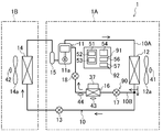
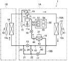
- FIG. 1 is a piping system diagram showing a configuration of a refrigeration apparatus according to Embodiment 1 of the present invention.
- FIG. 2 is a drive circuit of the power supply apparatus according to the first embodiment.
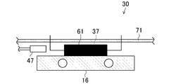
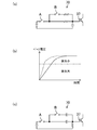
- FIG. 3 is a cross-sectional view showing the vicinity of the power element and the cooler according to the first embodiment.
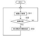
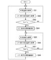
- FIG. 4 is a flowchart illustrating the dew condensation suppression operation control according to the first embodiment.
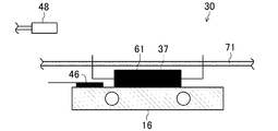
- FIG. 5 is a cross-sectional view showing the vicinity of the power element and the cooler according to the second embodiment.
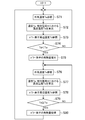
- FIG. 6 is a flowchart illustrating the dew condensation suppression operation control according to the second embodiment.
- FIG. 7 is a flowchart illustrating the dew condensation suppression operation control according to the third embodiment.
- FIG. 8 is a flowchart illustrating the dew condensation suppression operation control according to the fourth embodiment.
- FIG. 9 is a cross-sectional view showing the vicinity of the power element and the cooler according to the fifth embodiment.
- FIG. 10 is a flowchart illustrating the dew condensation suppression operation control according to the fifth embodiment.
- FIG. 11 is a cross-sectional view showing the vicinity of the power element and the cooler according to the sixth embodiment.
- FIG. 12 is a flowchart illustrating the dew condensation suppression operation control according to the sixth embodiment.
- FIG. 13 is a piping diagram illustrating the configuration of the refrigeration apparatus according to the seventh embodiment.
- FIG. 14 is a flowchart illustrating the dew condensation suppression operation control according to the seventh embodiment.
- FIG. 15 is a flowchart illustrating the dew condensation suppression operation control according to the eighth embodiment.
- FIG. 16 is a flowchart illustrating the dew condensation suppression operation control according to the ninth embodiment.
- FIG. 17 is a flowchart illustrating the dew condensation suppression operation control according to the tenth embodiment.
- FIG. 18 is a flowchart illustrating the dew condensation suppression operation control according to the eleventh embodiment.
- FIG. 19 is a flowchart illustrating the dew condensation suppression operation control according to the twelfth embodiment.
- FIG. 20A shows the ON / OFF control of the switching element in the normal operation control of the thirteenth embodiment over time
- FIG. 20B shows ON / OFF of the switching element in the dew condensation suppression operation control of the thirteenth embodiment.
- FIG. 21A and FIG. 21C each show an example of the base circuit of the power supply device of the fourteenth embodiment
- FIG. 21B shows the base in the normal operation and the dew condensation suppressing operation of the fourteenth embodiment.
- FIG. 22 is a diagram illustrating the relationship between the current phase input from each drive circuit to each drive unit and the conduction loss of the power element in the first example of increasing the conduction loss of the power element according to the fifteenth embodiment.
- FIG. 23 is a diagram comparing and comparing voltages between emitter collectors in normal operation control and dew condensation suppression operation control in the second example of increasing the conduction loss of the power element according to the fifteenth embodiment.
- FIG. 21A and FIG. 21C each show an example of the base circuit of the power supply device of the fourteenth embodiment
- FIG. 21B shows the base in the normal operation and the dew condensation suppressing operation of the fourteenth embodiment.
- FIG. 22 is a diagram illustrating the relationship between the current phase input from each drive circuit to each drive unit and the conduction loss of the power element
- FIG. 24 shows an example of a drive circuit for changing the voltage between the emitter and collector in the second example of increasing the conduction loss of the power element according to the fifteenth embodiment.
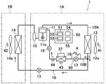
- FIG. 25 is a piping diagram illustrating the configuration of the refrigeration apparatus according to the sixteenth embodiment.
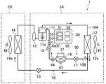
- FIG. 26 is a piping diagram illustrating the configuration of the refrigeration apparatus according to the seventeenth embodiment.
- FIG. 27 is a piping diagram illustrating the configuration of the refrigeration apparatus according to the eighteenth embodiment.
- FIG. 28 is a piping diagram illustrating the configuration of the refrigeration apparatus according to the nineteenth embodiment.
- FIG. 29 is a piping diagram illustrating the configuration of the refrigeration apparatus according to the twentieth embodiment.
- FIG. 30 is a piping diagram illustrating another configuration of the refrigeration apparatus according to the twentieth embodiment.
- FIG. 31 is a piping diagram illustrating the configuration of the refrigeration apparatus according to the twenty-second embodiment.
- FIG. 32 is a piping diagram illustrating the configuration of the refrigeration apparatus according to the twenty-third embodiment.
- FIG. 33 is a piping diagram illustrating a configuration of a refrigeration apparatus according to Embodiment 24.
- FIG. 34 is a piping diagram illustrating a configuration of a refrigeration apparatus according to Embodiment 25.
- FIG. 35 is a piping diagram illustrating a configuration of a refrigeration apparatus according to Embodiment 26.
- FIG. 36 is a piping diagram illustrating a configuration of a refrigeration apparatus according to Embodiment 27.
- FIG. 37 is a piping diagram illustrating a configuration of a refrigeration apparatus according to Embodiment 28.
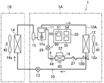
- a refrigeration apparatus (1) has a heat source side unit (1A) and a use side unit (1B), and performs a refrigerant compression circuit (10 ).
- the refrigeration apparatus according to the present invention may be, for example, an air conditioner or a cooling apparatus that cools the inside of a refrigerator or a freezer, but in this embodiment, the air conditioner that cools indoor air.
- the apparatus will be described as an example.
- the refrigerant circuit (10) includes a main circuit (10A) in which a compressor (11), a heat source side heat exchanger (12), an expansion valve (13), and a use side heat exchanger (14) are connected in order by a refrigerant pipe. ).
- the main circuit (10A) is configured so that the refrigerant circulates in one direction and does not circulate in the reverse direction. Therefore, in this embodiment, the heat source side heat exchanger (12) always functions as a condenser, and the use side heat exchanger (14) always functions as an evaporator.
- the heat source side heat exchanger (12) and the use side heat exchanger (14) are each constituted by a cross fin type fin-and-tube heat exchanger, and the refrigerant of the main circuit (10A) Heat exchange with air.
- the compressor (11) includes a motor (11a) that is rotationally driven by a power supply device (30) described later. Although details will be described later, the rotation speed of the motor (11a) can be adjusted by the power supply device (30). Further, an accumulator (15) is provided on the suction side of the compressor (11) for removing the liquid refrigerant contained in the refrigerant and causing the compressor (11) to suck only the gas refrigerant.
- the refrigerant circuit (10) has a branch circuit (10B) that branches from between the heat source side heat exchanger (12) of the main circuit (10A) and the expansion valve (13).
- the outflow end of the branch circuit (10B) is connected to the compressor (11).
- the outflow end of the branch circuit (10B) is connected to an intermediate port communicating with the compression chamber in the middle of compression of the compressor (11).
- the branch circuit (10B) is provided with a cooler (16) for cooling a power element (37) described later. Further, a first throttle valve (18) and a second throttle valve (17) whose opening degree is variable are provided on the upstream side and the downstream side of the cooler (16) of the branch circuit (10B), respectively.
- the heat source side fan (12a) is provided in the vicinity of the heat source side heat exchanger (12), while the use side fan (14a) is provided in the vicinity of the use side heat exchanger (14).
- the compressor (11), the heat source side heat exchanger (12), the heat source side fan (12a), the expansion valve (13), and the branch circuit (10B) are provided in the heat source side unit (1A) and use side heat The exchanger (14) and the use side fan (14a) are provided in the use side unit (1B).
- the heat source side unit (1A) is provided with a power supply device (30) for supplying power to each drive unit of each component of the refrigerant circuit (10).
- the power supply device (30) includes a drive circuit (31) for controlling and converting the power supplied to each drive unit such as the motor (11a) of the compressor (11).
- FIG. 2 shows a drive circuit (31) for the compressor (11) connected to the motor (11a) of the compressor (11) as an example of the drive circuit (31).
- the drive circuit (31) is a rectifier circuit (32) connected to a commercial power source (38), a capacitor circuit (33), and an inverter circuit connected to a motor (11a) of a compressor (11) as a drive unit. (34).
- the rectifier circuit (32) is connected to a commercial power source (38) that is a three-phase AC power source.
- the rectifier circuit (32) is a circuit for converting the AC voltage of the commercial power supply (38) into a DC voltage, and six diodes (35) are connected in a three-phase bridge.
- the capacitor circuit (33) is connected between the rectifier circuit (32) and the inverter circuit (34), and includes a capacitor (36).
- the inverter circuit (34) converts the DC voltage of the capacitor circuit (33) into a three-phase AC voltage and supplies the converted AC voltage to the motor (11a) serving as a load.
- the switching element constitutes the power element (37) according to the present invention, and for example, an IGBT (Insulated Gate Bipolar Transistor), a MOS-FET (MOS Field Effect Transistor), or the like is used.
- IGBT Insulated Gate Bipolar Transistor
- MOS-FET MOS Field Effect Transistor
- the switching of the switching element is controlled, whereby the AC voltage output to the motor (11a) and its frequency are increased and decreased, and the rotational speed of the motor (11a) is adjusted.
- the switching of the switching element is controlled by the control device (60).
- the AC voltage of the commercial power source (38) is converted into a DC voltage in the rectifier circuit (32), and the DC voltage is converted into an AC voltage of a desired frequency in the inverter circuit (34). After converting into voltage, it supplies to drive parts, such as a motor (11a) of a compressor (11).
- each power element (37) of the compressor (11) and the drive circuit (31) of each component is bundled to form one power module (61). Forming.
- the power module (61) is mounted on a substrate (71) provided in the heat source unit (1A) together with other electrical components (not shown).
- the power element (37) generates heat at a high temperature during operation. Therefore, a cooler (16) for cooling the power element (37) with the refrigerant flowing through the refrigerant circuit (10) is provided. Note that, as described above, in the present embodiment, the power elements (37) for the respective component parts are collectively configured as one power module (61). Therefore, as shown in FIG. 3, the cooler (16) is provided to cool the power module (61).
- the cooler (16) is formed in a flat rectangular parallelepiped shape by a metal such as aluminum, for example, and a refrigerant flow path for circulating the refrigerant therein is formed.
- the refrigerant flow path may be formed by inserting a part of the refrigerant pipe, or may be formed by connecting the refrigerant pipe to a tubular through hole. In this embodiment, it is formed by a part of the branch circuit (10B) of the refrigerant circuit (10) inserted through the cooler (16) (see FIG. 1).
- the cooler (16) is configured to be able to circulate the refrigerant flowing through the refrigerant circuit (10).
- the cooler (16) is configured by a metal such as aluminum so that the cold heat of the refrigerant circulating in the interior is transmitted to the outer surface.
- the heat source side unit (1A) is provided with an outside air temperature sensor (41) for detecting the outside air temperature (the temperature of the air before passing through the heat source side heat exchanger (12)).
- the use side unit (1B) is provided with an indoor temperature sensor (42) for detecting the room temperature (the temperature of the air before passing through the use side heat exchanger (14)).
- the cooler (16) is provided with an evaporation temperature sensor (43) for detecting the evaporation temperature of the refrigerant in the cooler (16).
- An outlet temperature sensor (44) for detecting the refrigerant temperature on the outlet side of the cooler (16) is provided on the downstream side of the cooler (16) of the branch circuit (10B).
- the cooler (16) is provided with a dew condensation sensor (45) for detecting dew condensation in the cooler (16).
- the dew condensation sensor (45) is attached to the surface of the cooler (16) facing the power module (61).
- the outside air temperature sensor (41), the indoor temperature sensor (42), the evaporation temperature sensor (43), the outlet temperature sensor (44), and the dew condensation sensor (45) are each connected to an operation control device (50) to be described later. A detection signal is transmitted to the control device (50).
- the heat source side unit (1A) is provided with an operation control device (50) for drivingly controlling the drive unit of each component of the refrigerant circuit (10).
- the operation control device (50) is connected to a control device (60) connected to each drive circuit (31), and transmits a control signal for controlling each drive circuit (31) to the control device (60).
- the control device (60) controls the switching of the switching elements constituting the power element (37) based on the control signal from the operation control device (50), thereby supplying the AC voltage supplied to each drive unit and Control its frequency. Specifically, if the drive control unit (50) is in a desired state (for example, the motor (11a) based on the detected values of the outside air temperature sensor (41), the indoor temperature sensor (42), etc. A control signal is transmitted to the control device (60) so as to achieve a desired rotation speed or rotation speed. The control device (60) converts the control signal into a drive signal, and outputs the drive signal to the drive circuit (31) of each drive unit.
- a desired state for example, the motor (11a) based on the detected values of the outside air temperature sensor (41), the indoor temperature sensor (42), etc.
- a control signal is transmitted to the control device (60) so as to achieve a desired rotation speed or rotation speed.
- the control device (60) converts the control signal into a drive signal, and outputs the drive signal to
- the drive signal is input to a base circuit (not shown) of each switching element, and ON / OFF of each switching element is controlled.
- the alternating voltage supplied to each drive part is controlled to a desired voltage and frequency, for example, the rotation speed of a motor (11a) etc. turns into a desired rotation speed.
- the operation control device (50) adjusts the temperature and superheat degree of the refrigerant passing through the cooler (16) and performs a normal operation unit (51) for performing a normal operation, and a dew condensation suppressing operation described later.
- the dew condensation determination part (54) and the forced reduction part (55) are provided.
- the normal operation section (51) includes a first opening adjustment section (52) for adjusting the opening degree of the first throttle valve (18) and a second opening degree for adjusting the opening degree of the second throttle valve (17). And an adjustment unit (53).
- the first opening degree adjusting unit (52) adjusts the opening degree of the first throttle valve (18) so that the evaporation temperature of the refrigerant in the cooler (16) becomes the target temperature. Specifically, the first opening degree adjusting unit (52) reduces the opening degree of the first throttle valve (18) when the detected value of the evaporation temperature sensor (43) is lower than the target temperature, When the temperature is higher than the target temperature, the opening degree of the first throttle valve (18) is increased.
- the second opening degree adjusting unit (53) adjusts the opening degree of the second throttle valve (17) so that the superheat degree of the refrigerant on the outlet side of the cooler (16) becomes the target superheat degree.
- the second opening degree adjuster (53) is a value obtained by subtracting the detected value of the evaporation temperature sensor (43) from the detected value of the outlet temperature sensor (44) (the outlet side of the cooler (16)). Is lower than the target superheat degree, the opening degree of the second throttle valve (17) is reduced, whereas when it is higher than the target superheat degree, the opening degree of the second throttle valve (17) is reduced. Increase.
- the dew condensation determination unit (54) refers to the detection value (condensation signal) of the dew condensation sensor (45), and determines whether or not dew condensation has occurred in the cooler (16) based on the detection value. .
- the forced reduction unit (55) forces the opening of the first throttle valve (18) in place of the first opening adjustment unit (52) when the condensation determination unit (54) determines that the condensation is present. To reduce.
- the first throttle valve (18), the second throttle valve (17), the first opening degree adjusting unit (52), and the second opening degree adjusting unit (53) An adjustment mechanism (90) according to the invention is configured.
- the adjustment mechanism (90) according to the present invention may not include the second opening degree adjustment unit (53).
- the operation control device (50) that controls electric power supplied to the drive unit of each component of the refrigerant circuit (10) performs normal operation control and dew condensation suppression operation control described below.
- the operation control device (50) drives and controls various components of the refrigerant circuit (10) so that the room temperature becomes a desired temperature based on the detection values of the room temperature sensor (42) and the outside air temperature sensor (41). .
- the motor (11a) of the compressor (11) if the room temperature is higher than the desired temperature, the rotational speed of the motor (11a) of the compressor (11) is increased, and the room temperature is lower than the desired temperature. If it is low, the rotational speed of the motor (11a) of the compressor (11) is reduced.
- the normal operation unit (51) of the operation control device (50) adjusts the temperature and superheat degree of the refrigerant passing through the cooler (16). Specifically, the first opening degree adjusting unit (52) adjusts the opening degree of the first throttle valve (18) so that the evaporation temperature of the refrigerant in the cooler (16) becomes the target temperature. Further, the second opening degree adjusting unit (53) adjusts the opening degree of the second throttle valve (17) so that the superheat degree of the refrigerant on the outlet side of the cooler (16) becomes the target superheat degree. More specifically, the first opening degree adjusting unit (52) reduces the opening degree of the first throttle valve (18) when the evaporation temperature in the cooler (16) is lower than the target temperature.
- the second opening degree adjusting unit (53) reduces the opening degree of the second throttle valve (17) when the refrigerant superheat degree on the outlet side of the cooler (16) is lower than the target superheat degree, When it is higher than the target superheat degree, the opening degree of the second throttle valve (17) is increased. As a result, the temperature of the refrigerant passing through the cooler (16) becomes the target temperature, and the refrigerant introduced into the compressor (11) is prevented from getting wet.
- the temperature of the cooler (16) and its surrounding members (for example, the power module (61) and the substrate (71)) is different from the dew point temperature of the surrounding air, although it depends on the operating conditions and the outside air conditions. Condensation may occur in the cooler (16) and surrounding members. Therefore, in parallel with the normal operation control, the following dew condensation suppression operation control is executed every predetermined time (for example, every 30 seconds).
- the dew condensation determination unit (54) refers to the dew condensation signal from the dew condensation sensor (45) (step S11), and whether or not the dew condensation state has occurred in the cooler (16). Is determined (step S12). And if the dew condensation determination part (54) determines with a dew condensation state, a forced reduction part (55) will replace the said 1st opening degree adjustment part (52) with a 1st throttle valve (18) (1st adjustment valve). ) Is forcibly reduced by a predetermined value (step S13).
- the operation control device (50) After the opening of the first throttle valve (18) is forcibly reduced by the forced reduction unit (55) as described above, the operation control device (50) returns to step S11 again and repeats the same operation. As a result, the opening degree of the first throttle valve (18) is reduced every time the forced reduction unit (55) performs the dew condensation suppression operation control while the dew condensation determination unit (54) determines the dew condensation state. . Then, when the dew condensation determination unit (54) does not determine that it is in the dew condensation state, the operation control device (50) resumes normal operation control, and changes the evaporating temperature of the refrigerant in the cooler (16) to the target temperature. Adjust the opening of the throttle valve (18).
- the adjusting mechanism (90) is provided so that the temperature of the refrigerant passing through the cooler (16) can be adjusted. Can be adjusted to temperature. That is, the temperature of the refrigerant passing through the cooler (16) can be adjusted in accordance with the amount of heat generated by the power element (37) and the change in the installation environment of the power element (37). Therefore, insufficient cooling and excessive cooling of the power element (37) by the cooler (16) can be suppressed, and the cooling efficiency of the power element (37) by the cooler (16) can be improved.
- the first opening degree adjusting unit (52) for adjusting the opening degree of the first throttle valve (18) so that the evaporation temperature of the refrigerant in the cooler (16) becomes the target temperature By providing, the temperature of the cooler (16) can be adjusted to an appropriate temperature with an easy configuration.
- the second opening degree adjusting unit (the second opening degree adjusting unit (16) that adjusts the opening degree of the second throttle valve (17) so that the refrigerant superheat degree on the outlet side of the cooler (16) becomes the target superheat degree. 53) can prevent the wetting of the refrigerant that cools the power element (37) and returns to the compressor (11), thereby preventing the compressor (11) from being damaged due to the suction of the liquid refrigerant. be able to.
- the forced reduction unit (55) when the dew condensation determination unit (54) determines the dew condensation state, the forced reduction unit (55) The opening degree of the first throttle valve (18) is forcibly reduced. As a result, the amount of refrigerant flowing into the cooler (16) is reduced and the amount of heat absorbed by the cooler (16) is reduced, so that excessive temperature drop of the power element (37) and cooler (16) is suppressed. Can do. Therefore, it is possible to suppress the occurrence of condensation in the power element (37) and the peripheral members (16, 71) of the power element (37). Corrosion and power elements (such as metal parts disposed in the vicinity thereof) 37) can prevent the insulation performance from deteriorating.
- the dew condensation sensor (45) since the dew condensation sensor (45) is used, it is possible to easily and accurately detect the presence or absence of dew condensation.
- the condensation sensor (45) is attached to the cooler (16) to detect the occurrence of condensation at a relatively early stage. Therefore, for example, when condensation has occurred in the cooler (16) but the condensation has not yet occurred in the power element (37), the opening degree of the first throttle valve (18) is reduced to reduce the power element (37). The occurrence of condensation in 37) can be prevented beforehand.
- the dew condensation sensor (45) is attached to the power element (37) (in this embodiment, the power module (61)) or a peripheral member of the power element (37) (for example, the substrate (71)). May be.
- a temperature sensor (46) is provided in the vicinity of the power element (37) instead of the dew condensation sensor (45) of the first embodiment.
- the outside temperature sensor (41) is used as an air temperature sensor according to the present invention for detecting the temperature of air around the power supply device (30).
- the temperature sensor (46) and the outside air temperature sensor (41) are detection units that detect physical quantities for determining whether or not the condensation state is present. Used.
- the temperature sensor (46) is attached to the surface of the cooler (16) facing the power module (61).
- the temperature sensor (46) is connected to the operation control device (50), and transmits a detection signal to the operation control device (50).
- the dew determination unit ⁇ (54) of the operation control device (50) includes the power element (37) and the power element when the detected value of the temperature sensor (46) is lower than the detected value of the outside air temperature sensor (41). It is determined that there is a high possibility that condensation will occur on the peripheral members (16, 71) of (37). Since other configurations are the same as those of the first embodiment, description thereof is omitted.
- the operation of the refrigeration cycle, the cooling operation of the power element, and the normal operation control by the operation control device (50) are the same as in the first embodiment.
- the dew condensation suppression operation control by the operation control device (50) will be described.
- the dew condensation determination unit 54 refers to the detection value Ta (outside air temperature) of the outside air temperature sensor (41) (step S21), and subsequently, the detection value Td of the temperature sensor (46). Reference is made to (temperature of cooler (16)) (step S22).
- the dew condensation determination unit (54) determines whether or not the dew condensation state is likely to cause dew condensation on the cooler (16) (step S23).
- the dew condensation determination unit ⁇ (54) determines the dew condensation state when the detection value Td of the temperature sensor (46) is lower than the detection value Ta of the outside air temperature sensor (41).
- step S23 if it determines with the dew condensation determination part (54) being in a dew condensation state, a forced reduction part (55) will replace the said 1st opening degree adjustment part (52) of a 1st throttle valve (18).
- the opening is forcibly reduced by a predetermined value (step S24).
- the operation control device (50) After the opening of the first throttle valve (18) is forcibly reduced by the forced reduction unit (55) as described above, the operation control device (50) returns to step S21 again and repeats the same operation. As a result, the opening degree of the first throttle valve (18) is reduced every time the forced reduction unit (55) performs the dew condensation suppression operation control while the dew condensation determination unit (54) determines the dew condensation state. . Then, when the dew condensation determination unit (54) does not determine that it is in the dew condensation state, the operation control device (50) resumes normal operation control, and changes the evaporating temperature of the refrigerant in the cooler (16) to the target temperature. Adjust the opening of the throttle valve (18).
- Embodiment 2 since the state of the air before passing through the heat source side heat exchanger (12) (the state of the external air) and the state of the air around the power supply device (30) are substantially the same, the outside air temperature
- the sensor (41) is used as an air temperature sensor according to the present invention.
- the temperature sensor (46) provided in the cooler (16) in the vicinity of the power element (37) and the outside air temperature sensor (41) are used as a detection unit.
- the dew point temperature of the external air (the power supply device (30))
- the dew point temperature of the ambient air) is lower than the temperature of the external air (the dry bulb temperature of the ambient air of the power supply device (30)). Therefore, in a state where the detection value Td of the temperature sensor (46) is lower than the detection value Ta of the outside air temperature sensor (41), the surface temperature of the cooler (16) is the dew point temperature of the external air (the power supply device (30)
- the dew point temperature of the surrounding air is approaching, and it can be assumed that there is a high possibility that condensation occurs in the power element (37) and the cooler (16).
- the dew condensation determination unit (54) determines that the dew condensation state is present when the detection value Td of the temperature sensor (46) is lower than the detection value Ta of the outside air temperature sensor (41).
- the temperature sensor (46) and the outside air temperature sensor (41) dew condensation occurs on the power element (37) or the peripheral members (16, 71) of the power element (37). It can be detected easily and accurately that the possibility of occurrence is high. Further, since the amount of heat generated by the power element (37) is increased at the time when the possibility of the occurrence of condensation is increased, the occurrence of condensation can be prevented in advance.
- the temperature of the cooler (16) for cooling the power element (37) is lower than that of the power element (37) during operation. Therefore, by attaching the temperature sensor (46) to the cooler (16), the possibility of the occurrence of condensation can be detected at a relatively early stage, and the power element (37) and the periphery of the power element (37) can be detected. The occurrence of condensation on the members (16, 71) can be more reliably prevented.
- the temperature sensor (46) is attached to the power element (37) (in this embodiment, the power module (61)) or a peripheral member of the power element (37) (for example, the substrate (71)). May be.
- the outside temperature sensor (41) is also used as the air temperature sensor according to the present invention.
- the air temperature sensor according to the present invention includes an electric power supply device (41) in addition to the outside temperature sensor (41). It is only necessary that the temperature of the air around 30) can be detected, and the temperature of the air around the power supply device (30) in the heat source unit (1A) may be detected.
- Embodiment 3 of the Invention The refrigeration apparatus (1) according to the third embodiment is configured in the same manner as in the second embodiment, and the method for determining the dew condensation by the dew condensation determination unit (54) of the operation control apparatus (50) is different. Since the other configurations and operations are the same as those in the second embodiment, the following describes the dew condensation suppression operation control by the operation control device (50) different from the second embodiment.
- the dew condensation determination unit (54) first refers to the detected value Ta (outside air temperature) of the outside air temperature sensor (41) (step S31). Next, the dew condensation determination unit (54) calculates the dew point temperature Tw when the air temperature is Ta and the relative humidity is Hl based on the detected value Ta of the outside air temperature sensor (41) (step S32). . And the dew condensation determination part (54) refers to the detected value (temperature Td of the cooler (16)) of the temperature sensor (46) (step S33).
- the dew condensation determination unit (54) determines whether or not the dew condensation state is likely to cause dew condensation on the cooler (16) (step S34).
- the dew condensation determination unit 54 (54) determines the dew condensation state when the detection value Td of the temperature sensor (46) is lower than the dew point temperature Tw.
- a forced reduction part (55) will predetermine the opening degree of a 1st throttle valve (18) instead of the said 1st opening degree adjustment part (52). Is forcibly reduced by the value of (step S35).
- the operation control device (50) After the opening of the first throttle valve (18) is forcibly reduced by the forced reduction unit (55) as described above, the operation control device (50) returns to step S31 again and repeats the same operation. As a result, the opening degree of the first throttle valve (18) is reduced every time the forced reduction unit (55) performs the dew condensation suppression operation control while the dew condensation determination unit (54) determines the dew condensation state. . Then, when the dew condensation determination unit (54) does not determine that it is in the dew condensation state, the operation control device (50) resumes normal operation control, and changes the evaporating temperature of the refrigerant in the cooler (16) to the target temperature. Adjust the opening of the throttle valve (18).
- Embodiment 3 since the state of the air before passing through the heat source side heat exchanger (12) (the state of the external air) and the state of the air around the power supply device (30) are substantially the same, the outside air temperature
- the sensor (41) is used as an air temperature sensor according to the present invention.
- the temperature sensor (46) provided in the cooler (16) in the vicinity of the power element (37) and the outside air temperature sensor (41) are used as a detection unit.
- the dew condensation determination unit (54) is detected from the detected value Ta of the outside air temperature sensor (41) and the predicted relative humidity Hl (for example, 60%), so that the heat source unit
- the dew point temperature Tw of the external air of (1A) is estimated, and when the detection value Td of the temperature sensor (46) is lower than the dew point temperature Tw, it is determined that the dew condensation state is present.
- the temperature sensor (46) and the outside air temperature sensor (41) by using the temperature sensor (46) and the outside air temperature sensor (41), dew condensation occurs on the power element (37) or the peripheral member (16, 71) of the power element (37). Can be detected easily and accurately. Moreover, since the opening degree of the first throttle valve (18) is reduced and the temperature drop of the cooler (16) is suppressed when the possibility of the occurrence of condensation is increased, the occurrence of condensation is prevented in advance. Can do.
- the temperature of the cooler (16) for cooling the power element (37) is lower than that of the power element (37) during operation. Therefore, by attaching the temperature sensor (46) to the cooler (16), the possibility of the occurrence of condensation can be detected at a relatively early stage, and the power element (37) and the periphery of the power element (37) can be detected. The occurrence of condensation on the members (16, 71) can be more reliably prevented.
- the temperature sensor (46) is attached to the power element (37) (in this embodiment, the power module (61)) or a peripheral member of the power element (37) (for example, the substrate (71)). May be.
- the outside temperature sensor (41) is also used as the air temperature sensor according to the present invention.
- the air temperature sensor according to the present invention includes an electric power supply device (41) in addition to the outside temperature sensor (41). It is only necessary that the temperature of the air around 30) can be detected, and the temperature of the air around the power supply device (30) in the heat source unit (1A) may be detected.
- Embodiment 4 of the Invention The refrigeration apparatus (1) according to the fourth embodiment is configured in the same manner as in the second embodiment, and the method for determining the dew condensation by the dew condensation determination unit (54) of the operation control apparatus (50) is different from that of the second embodiment. Since the other configurations and operations are the same as those in the second embodiment, the following describes the dew condensation suppression operation control by the operation control device (50) different from the second embodiment.
- the dew condensation determination unit (54) first refers to the detected value of the temperature sensor (46) (temperature Td of the cooler (16)) (step S36). Next, the dew condensation determination unit (54) added to the detected value Td of the temperature sensor (46) a temperature increase ⁇ T from the installation part of the temperature sensor (46) to the electrical connection part of the power element (37). The temperature (Td + ⁇ T) is calculated (step S37). The temperature increase ⁇ T may be a value measured in advance in the test or a value predicted from the thermal resistance and the heat flow rate. Then, the dew condensation determination unit (54) refers to the detected value Ta (outside air temperature) of the outside temperature sensor (41) (step S38).
- the dew condensation determination unit (54) determines whether or not the dew condensation state is likely to cause dew condensation on the cooler (16) (step S39).
- the dew condensation determination unit ⁇ (54) determines that the dew state is present when the temperature (Td + ⁇ T) is lower than the outside air temperature Ta.
- a forced reduction part (55) will predetermine the opening degree of a 1st throttle valve (18) instead of the said 1st opening degree adjustment part (52). Is forcibly reduced by the value of (step S40).
- the operation control device (50) After the opening of the first throttle valve (18) is forcibly reduced by the forced reduction unit (55) as described above, the operation control device (50) returns to step S36 again and repeats the same operation. As a result, the opening degree of the first throttle valve (18) is reduced every time the forced reduction unit (55) performs the dew condensation suppression operation control while the dew condensation determination unit (54) determines the dew condensation state. . Then, when the dew condensation determination unit (54) does not determine that it is in the dew condensation state, the operation control device (50) resumes normal operation control, and changes the evaporating temperature of the refrigerant in the cooler (16) to the target temperature. Adjust the opening of the throttle valve (18).
- Embodiment 4- by using the temperature sensor (46) and the outside air temperature sensor (41), condensation occurs on the power element (37) or the peripheral members (16, 71) of the power element (37). It is possible to easily and accurately detect that the possibility is high. Moreover, since the opening degree of the first throttle valve (18) is reduced and the temperature drop of the cooler (16) is suppressed when the possibility of the occurrence of condensation is increased, the occurrence of condensation is prevented in advance. Can do.
- the power element (37) near the cooler (16) may be short-circuited due to the condensation of condensed water due to heat generated by the power element (37) even in a temperature environment where condensation occurs. ) May not be in a temperature environment where condensation occurs. Therefore, in the fourth embodiment, when the predicted temperature of the electrical connection portion of the power element (37) that may be short-circuited due to the attachment of condensed water is lower than the air temperature, the forced reduction portion (55) The opening of one throttle valve (18) is forcibly reduced to prevent condensation from occurring. Thereby, the refrigerant
- the temperature sensor (46) is attached to the power element (37) (in this embodiment, the power module (61)) or a peripheral member of the power element (37) (for example, the substrate (71)). May be.
- the outside temperature sensor (41) is also used as the air temperature sensor according to the present invention.
- the air temperature sensor according to the present invention is not limited to the outside temperature sensor (41), but the power supply device ( It is only necessary that the temperature of the air around 30) can be detected, and the temperature of the air around the power supply device (30) in the heat source unit (1A) may be detected.
- Embodiment 5 of the Invention is provided with a humidity sensor (47) in the vicinity of the power element (37) instead of the dew condensation sensor (45) of the first embodiment. (47) is used as a detection unit for detecting a physical quantity for determining whether or not a dew condensation state is present.
- the humidity sensor (47) is connected to the operation control device (50) and transmits a detection signal to the operation control device (50).
- the dew determination unit ⁇ (54) of the operation control device (50) allows the power element (37) and the periphery of the power element (37) when the detected value of the humidity sensor (47) is higher than a predetermined upper limit value. It is determined that a dew condensation state that causes dew condensation on the members (16, 71). Since other configurations are the same as those of the first embodiment, description thereof is omitted.
- the operation of the refrigeration cycle, the cooling operation of the power element, and the normal operation control by the operation control device (50) are the same as in the first embodiment.
- the dew condensation suppression operation control by the operation control device (50) will be described.
- the dew condensation determination unit (54) refers to the detection value Hp of the humidity sensor (47) (step S41).
- the dew condensation determination unit (54) determines whether or not the power element (37) or the peripheral member (16, 71) of the power element (37) is in a dew condensation state that is highly likely to cause dew condensation. (Step S42).
- the dew condensation determination unit ⁇ (54) determines the dew condensation state when the detected value Hp of the humidity sensor (47) is higher than a predetermined upper limit value Hm.
- a forced reduction part (55) will open the 1st throttle valve (18) instead of the said 1st opening degree adjustment part (52).
- the degree is forcibly reduced by a predetermined value (step S43).
- the operation control device (50) After the opening of the first throttle valve (18) is forcibly reduced by the forced reduction unit (55) as described above, the operation control device (50) returns to step S41 again and repeats the same operation. As a result, the opening degree of the first throttle valve (18) is reduced every time the forced reduction unit (55) performs the dew condensation suppression operation control while the dew condensation determination unit (54) determines the dew condensation state. . Then, when the dew condensation determination unit (54) does not determine that it is in the dew condensation state, the operation control device (50) resumes normal operation control, and changes the evaporating temperature of the refrigerant in the cooler (16) to the target temperature. Adjust the opening of the throttle valve (18).
- Embodiment 5- by using the humidity sensor (47), it is easy and accurate that condensation is likely to occur on the power element (37) or the peripheral members (16, 71) of the power element (37). It can be detected well. In addition, since the opening of the first throttle valve (18) is forcibly reduced when the possibility that condensation will occur increases, the temperature drop of the cooler (16) is suppressed. Can be prevented.
- the refrigeration apparatus (1) according to Embodiment 6 further includes a humidity sensor (48) that detects the temperature of air around the power supply apparatus (30) in addition to the refrigeration apparatus (1) of Embodiment 2. Is provided.
- a humidity sensor 48
- the humidity sensor (48) is for detecting the humidity of the outside air before reaching the cooler (16), and is provided upstream of the air flow cooler (16).
- the humidity sensor (48) is connected to the operation control device (50) and transmits a detection signal to the operation control device (50).
- the detected value of the temperature sensor (46) is calculated from the detected value of the humidity sensor (48) and the detected value of the outside air temperature sensor (41).
- the temperature is lower than the dew point temperature, it is determined that the condensation state is likely to cause condensation on the power element (37) and the peripheral members (16, 71) of the power element (37). Since other configurations are the same as those of the second embodiment, description thereof is omitted.
- the operation of the refrigeration cycle, the cooling operation of the power element, and the normal operation control by the operation control device (50) are the same as in the second embodiment.
- the dew condensation suppression operation control by the operation control device (50) will be described.
- the dew condensation determination unit (54) refers to the detected value Ta (outside air temperature) of the outside air temperature sensor (41) and also refers to the detected value Ha (outside air humidity) of the humidity sensor (48). (Step S44). Next, the dew condensation determination unit 54 (54) determines that the air temperature is Ta and the relative humidity is Ha based on the detection value Ta of the outside air temperature sensor (41) and the detection value Ha of the humidity sensor (48). The dew point temperature Tw is calculated (step S45). Then, the dew condensation determination unit 54 (54) refers to the detection value of the temperature sensor (46) (the temperature Td of the cooler (16)) (step S46).
- the dew condensation determination unit (54) determines whether or not the dew condensation state is likely to cause dew condensation on the cooler (16) (step S47).
- the dew condensation determination unit 54 (54) determines the dew condensation state when the detection value Td of the temperature sensor (46) is lower than the dew point temperature Tw.
- step S47 if it determines with the dew condensation determination part (54) being a dew condensation state, a forced reduction part (55) will replace the said 1st opening degree adjustment part (52) of a 1st throttle valve (18).
- the opening degree is forcibly reduced by a predetermined value (step S48).
- the operation control device (50) After the opening of the first throttle valve (18) is forcibly reduced by the forced reduction unit (55) as described above, the operation control device (50) returns to step S44 again and repeats the same operation. As a result, the opening degree of the first throttle valve (18) is reduced every time the forced reduction unit (55) performs the dew condensation suppression operation control while the dew condensation determination unit (54) determines the dew condensation state. . Then, when the dew condensation determination unit (54) does not determine that it is in the dew condensation state, the operation control device (50) resumes normal operation control, and changes the evaporating temperature of the refrigerant in the cooler (16) to the target temperature. Adjust the opening of the throttle valve (18).
- a humidity sensor (48) that detects the humidity of the outside air before reaching the cooler (16), an outside air temperature sensor (41) that is the same as that of the second embodiment, and a temperature sensor that is the same as that of the second embodiment. (46) is used as a detection unit.
- the dew condensation determination unit (54) obtains the dew point temperature of the air (outside air) before being cooled by the cooler (16) and the humidity, and the temperature in the vicinity of the power element (37) is the above dew point. When the temperature is lower than the temperature, it is determined that the dew condensation state is likely to cause dew condensation in the power element (37).
- the humidity sensor (48), the outside air temperature sensor (41), and the temperature sensor (46), the power element (37) or a peripheral member (16 of the power element (37) is provided. 71), it is possible to easily and accurately detect that condensation is likely to occur. Further, since the amount of heat generated by the power element (37) is increased at the time when the possibility of the occurrence of condensation is increased, the occurrence of condensation can be prevented in advance.
- the temperature of the cooler (16) for cooling the power element (37) is lower than that of the power element (37) during operation. Therefore, by attaching the temperature sensor (46) to the cooler (16), the possibility of the occurrence of condensation can be detected at a relatively early stage, and the power element (37) and the periphery of the power element (37) can be detected. The occurrence of condensation on the members (16, 71) can be more reliably prevented.
- the temperature sensor (46) is attached to the power element (37) (in this embodiment, the power module (61)) or a peripheral member of the power element (37) (for example, the substrate (71)). May be.
- the outside air temperature sensor (41) is also used as the air temperature sensor according to the present invention.
- the air temperature sensor according to the present invention includes the power supply device ( It is only necessary that the temperature of the air around 30) can be detected, and the temperature of the air around the power supply device (30) in the heat source unit (1A) may be detected.
- Embodiment 7 of the Invention As shown in FIG. 13, the refrigeration apparatus (1) according to Embodiment 7 is obtained by changing the configuration of the operation control apparatus (50) of Embodiment 1.
- the operation control device (50) includes the normal operation unit (51) and the dew condensation determination unit (54) similar to those in the first embodiment. Further, the operation control device (50) includes a calorific value increase unit (56) and a calorific value return unit (57) instead of the forced reduction unit (55) of the first embodiment.
- the heat generation amount increasing unit (56) increases the heat generation amount of the power element (37) when the dew condensation determining unit (54) determines that the dew condensation state is present.
- the heat generation amount increasing section (56) increases the current of the compressor (11), thereby increasing the heat generation amount of the power element (37) of the drive circuit (31) for the compressor (11). Increase.
- the heat generation amount increase unit (56) increases the heat generation amount of the power element (37) of the power module (61).
- the normal state before the increase is restored.
- the heat generation amount return unit (57) returns the current of the motor (11a) of the compressor (11) to the normal state before the increase, so that the power element of the drive circuit (31) for the compressor (11) Return the amount of heat generated in (37) to the normal state.
- the calorific value increasing portion (56) constitutes a temperature increasing portion (91) for increasing the temperature of the power element (37) according to the present invention.
- the calorific value return part (57) constitutes a temperature return part (92) for returning the temperature of the power element (37) raised by the temperature rise part (91) to a normal state.
- the operation of the refrigeration cycle, the cooling operation of the power element, and the normal operation control by the operation control device (50) are the same as in the first embodiment.
- the dew condensation suppression operation control by the operation control device (50) will be described.
- the dew condensation determination unit (54) refers to the dew condensation signal from the dew condensation sensor (45) (step S51), and whether or not the dew condensation state has occurred in the cooler (16). Is determined (step S52). And if the dew condensation determination part (54) determines with a dew condensation state, the emitted-heat amount increase part (56) will increase the emitted-heat amount of a power element (37) (step S53).
- the calorific value increasing section (56) increases the current of the compressor (11) to increase the calorific value of the power element (37) of the drive circuit (31) for the compressor (11). Increase.
- the various power elements (37) are collectively configured as one power module (61). For this reason, the amount of heat generated by the power element (37) that controls the compressor (11) increases, so that the temperature of the entire power module (61) rises. Therefore, the condensation of the power module (61) and its peripheral members (16, 71) is suppressed and the condensation of the cooler (16) is eliminated.
- the dew condensation determination unit (54) refers to the dew condensation signal from the dew condensation sensor (45). (Step S54), it is determined whether or not the dew condensation state of the cooler (16) has been eliminated (Step S55). If the dew condensation determination unit (54) determines that the dew condensation state has not been eliminated, the process returns to step S54 while increasing the heat generation amount of the power element (37), and again refers to the dew condensation signal of the dew condensation sensor (45). .
- step S55 the dew condensation determination unit (54) determines in step S55 that the dew condensation state has been eliminated
- the heat generation amount of the power element (37) of the drive circuit (31) for the compressor (11) is determined by the heat generation amount return unit (57). Is restored to the normal state before the increase (step S56). And it returns to step S51 and repeats the said flow.
- the heat generation amount increasing unit (56) causes the power element (37 ) To increase the temperature of the power element (37) and the peripheral members (16, 71) of the power element (37).
- the dew condensation determination unit (54) determines that the dew condensation has occurred in the cooler (16)
- the heat generation amount increasing unit (56) causes the power element (37 ) To increase the temperature of the power element (37) and the peripheral members (16, 71) of the power element (37).
- the heat generation amount increasing unit (56) causes the power element (37 ) to increase the temperature of the power element (37) and the peripheral members (16, 71) of the power element (37).
- the dew condensation sensor (45) is used to determine the dew condensation state when the dew condensation actually occurs in the cooler (16). 37) Increase the calorific value. Therefore, when the condensation does not actually occur, the heat generation amount of the power element (37) is not increased unnecessarily, and the loss caused by increasing the heat generation amount of the power element (37) can be reduced.
- the dew condensation sensor (45) since the dew condensation sensor (45) is used, it is possible to easily and accurately detect the occurrence of dew condensation.
- the condensation sensor (45) is attached to the cooler (16) to detect the occurrence of condensation at a relatively early stage. Therefore, for example, even when condensation occurs in the cooler (16), the amount of heat generated by the power element (37) can be increased when condensation is not yet generated in the power element (37). Thereby, the occurrence of condensation in the power element (37) can be prevented in advance.
- the dew condensation sensor (45) is attached to the power element (37) (in this embodiment, the power module (61)) or a peripheral member of the power element (37) (for example, the substrate (71)). May be.
- the condensation sensor (45) accurately detects the elimination of the dew condensation state, and immediately after the dew condensation state is eliminated, the heat generation amount return unit (57) generates the heat from the power element (37). The amount can be restored to the normal state before the increase. Therefore, it is possible to suppress the heat loss caused by increasing the heat generation amount of the power element (37) to the minimum necessary.
- the amount of heat generated by the power element (37) for the compressor (11) is increased by increasing the current of the compressor (11), and the various power elements (37) are grouped together.
- the temperature of the entire power module (61) made can be increased. Therefore, for example, the temperature of the power element (37) can be easily raised without using a heating means such as a heater. Therefore, it is possible to easily suppress the occurrence of condensation in the power element (37) and the peripheral members (16, 71) of the power element (37).
- Embodiment 8 of the Invention a temperature sensor (46) similar to that of the second embodiment is provided instead of the dew condensation sensor (45) of the seventh embodiment (see FIG. 5).
- the outside air temperature sensor (41) is used as an air temperature sensor according to the present invention for detecting the temperature of air around the power supply device (30).
- the temperature sensor (46) and the outside air temperature sensor (41) are detection units that detect physical quantities for determining whether or not a dew condensation state is present. Used.
- the dew condensation determination unit ⁇ (54) of the operation control device (50) is connected to the power element (37) when the detected value of the temperature sensor (46) is lower than the detected value of the outside air temperature sensor (41). ) And the peripheral state (16, 71) of the power element (37) is determined to be a dew condensation state. Since other configurations are the same as those of the seventh embodiment, description thereof is omitted.
- the operation of the refrigeration cycle, the cooling operation of the power element, and the normal operation control by the operation control device (50) are the same as in the seventh embodiment.
- the dew condensation suppression operation control by the operation control device (50) will be described.
- the dew condensation determination unit (54) refers to the detection value Ta (outside air temperature) of the outside air temperature sensor (41) (step S61), and then the detection value Td of the temperature sensor (46). Reference is made to (temperature of cooler (16)) (step S62).
- the dew condensation determination unit (54) determines whether or not the dew condensation state is highly likely to cause dew condensation in the cooler (16) (step S63).
- the dew condensation determination unit ⁇ (54) determines the dew condensation state when the detection value Td of the temperature sensor (46) is lower than the detection value Ta of the outside air temperature sensor (41).
- step S63 when the dew condensation determination unit 54 (54) determines that the dew condensation state is present, the heat generation amount increasing unit (56) increases the heat generation amount of the power element (37) (step S64).
- the dew condensation determination portion (54) refers to the detection value Ta of the outside air temperature sensor (41) (step S65). Reference is made to the detection value Td of the temperature sensor (46) (step S66).
- the dew condensation determination unit (54) determines whether or not the dew condensation state has been resolved (step S67).
- the dew condensation determination unit ⁇ (54) determines that the dew condensation state has been eliminated when the detected value Td of the temperature sensor (46) becomes a numerical value equal to or greater than the detected value Ta of the outside air temperature sensor (41).
- step S67 If the dew condensation determination unit (54) determines in step S67 that the dew condensation state has not been eliminated, the process returns to step S65 while increasing the heat generation amount of the power element (37), and again the detected value Ta of the outside air temperature sensor (41).
- the detected value Td of the temperature sensor (46) is referred to.
- the heat generation amount return unit (57) returns the heat generation amount of the power element (37) to the normal state before the increase (step S68). ). And it returns to step S61 and repeats the said flow.
- Embodiment 8- by using the temperature sensor (46) and the outside air temperature sensor (41) as in the second embodiment, the power element (37) or the peripheral member (16, 71) It is possible to easily and accurately detect that condensation is likely to occur. Further, since the amount of heat generated by the power element (37) is increased at the time when the possibility of the occurrence of condensation is increased, the occurrence of condensation can be prevented in advance.
- the refrigeration apparatus (1) according to the ninth embodiment is configured in the same manner as in the eighth embodiment, and the method of determining condensation by the condensation determination unit (54) of the operation control apparatus (50) is different from that of the eighth embodiment. Note that the method for determining condensation is the same as in the third embodiment. Below, the dew condensation suppression operation control by the operation control apparatus (50) different from Embodiment 8 is demonstrated.
- the dew condensation determination unit (54) refers to the detection value Ta (outside temperature) of the outside temperature sensor (41) (step S71).
- the dew condensation determination unit (54) calculates the dew point temperature Tw when the air temperature is Ta and the relative humidity is Hl based on the detected value Ta of the outside air temperature sensor (41) (step S72).
- the dew condensation determination part (54) refers to the detected value (temperature Td of the cooler (16)) of the temperature sensor (46) (step S73).
- the dew condensation determination unit (54) determines whether or not the dew condensation state is highly likely to cause dew condensation on the cooler (16) (step S74).
- the dew condensation determination unit 54 (54) determines the dew condensation state when the detection value Td of the temperature sensor (46) is lower than the dew point temperature Tw.
- the heat generation amount increasing unit (56) increases the heat generation amount of the power element (37) (step S75).
- the dew condensation determination unit (54) refers to the detection value Ta of the outside air temperature sensor (41) (step S76). Next, the dew condensation determination unit (54) calculates the dew point temperature Tw when the air temperature is Ta and the relative humidity is Hl (step S77). Then, the dew condensation determining unit (54) refers to the detection value Td of the temperature sensor (46) (step S78).
- the dew condensation determination unit (54) determines whether or not the dew condensation state has been resolved (step S79).
- the dew condensation determination unit ⁇ (54) determines that the dew condensation state has been eliminated when the detected value Td of the temperature sensor (46) becomes a numerical value equal to or higher than the calculated dew point temperature Tw.
- step S79 if the dew condensation determination unit (54) determines that the dew condensation state has not been eliminated, the process returns to step S76 while increasing the amount of heat generated by the power element (37), and again the detected value of the outside air temperature sensor (41).
- the dew point temperature Tw is calculated from Ta and the relative humidity H1, and the detected value Td of the temperature sensor (46) is referred to.
- the heat generation amount return unit (57) returns the heat generation amount of the power element (37) to the normal state before the increase (step S80). ). And it returns to step S71 and repeats the said flow.
- Embodiment 9- by using the temperature sensor (46) and the outside air temperature sensor (41) as in the third embodiment, the power element (37) or the peripheral members (16, 71) of the power element (37) is used. It is possible to easily and accurately detect that condensation is likely to occur. Further, since the amount of heat generated by the power element (37) is increased at the time when the possibility of the occurrence of condensation is increased, the occurrence of condensation can be prevented in advance.
- Embodiment 10 of the Invention The refrigeration apparatus (1) according to the tenth embodiment is configured in the same manner as in the eighth embodiment, and the method for determining the dew condensation by the dew condensation determination unit (54) of the operation control apparatus (50) is different from that in the eighth embodiment. Note that the method of determining condensation is the same as in the fourth embodiment. Below, the dew condensation suppression operation control by the operation control apparatus (50) different from Embodiment 8 is demonstrated.
- the dew condensation determination unit (54) first refers to the detected value of the temperature sensor (46) (temperature Td of the cooler (16)) (step S91). Next, the dew condensation determination unit (54) added to the detected value Td of the temperature sensor (46) a temperature increase ⁇ T from the installation part of the temperature sensor (46) to the electrical connection part of the power element (37). The temperature (Td + ⁇ T) is calculated (step S92). The temperature increase ⁇ T may be a value measured in advance in the test or a value predicted from the thermal resistance and the heat flow rate. Then, the dew condensation determination unit (54) refers to the detection value Ta (outside air temperature) of the outside air temperature sensor (41) (step S93).
- the dew condensation determination unit (54) determines whether or not the dew condensation state is likely to cause dew condensation on the cooler (16) (step S94).
- the dew condensation determination unit ⁇ (54) determines that the dew state is present when the temperature (Td + ⁇ T) is lower than the outside air temperature Ta.
- the heat generation amount increasing unit (56) increases the heat generation amount of the power element (37) (step S95).
- the dew condensation determination portion (54) refers to the detection value of the temperature sensor (46) (temperature Td of the cooler (16)). (Step S96). Next, the dew condensation determination unit (54) added to the detected value Td of the temperature sensor (46) a temperature increase ⁇ T from the installation part of the temperature sensor (46) to the electrical connection part of the power element (37). The temperature (Td + ⁇ T) is calculated (step S97). Then, the dew condensation determination unit (54) refers to the detection value Ta (outside air temperature) of the outside air temperature sensor (41) (step S98).
- the dew condensation determination unit (54) determines whether or not the dew condensation state has been resolved (step S99).
- the dew condensation determination unit ⁇ (54) determines that the dew condensation state has been eliminated when the temperature (Td + ⁇ T) becomes a numerical value equal to or higher than the detection value Ta of the outside air temperature sensor (41).
- step S99 when the dew condensation determination unit (54) determines that the dew condensation state has not been eliminated, the process returns to step S96 while increasing the heat generation amount of the power element (37).
- the heat generation amount return unit (57) returns the heat generation amount of the power element (37) to the normal state before the increase (step S100). ). And it returns to step S91 and repeats the said flow.
- Embodiment 10- by using the temperature sensor (46) and the outside air temperature sensor (41) as in the fourth embodiment, the power element (37) or the peripheral members (16, 71) of the power element (37) is used. It is possible to easily and accurately detect that condensation is likely to occur. Further, since the amount of heat generated by the power element (37) is increased at the time when the possibility of the occurrence of condensation is increased, the occurrence of condensation can be prevented in advance.
- the power element (37) near the cooler (16) may be short-circuited due to the condensation of condensed water due to heat generated by the power element (37) even in a temperature environment where condensation occurs. ) May not be in a temperature environment where condensation occurs. Therefore, in Embodiment 10 described above, when the predicted temperature of the electrical connection portion of the power element (37) that may be short-circuited due to the attachment of dew condensation water is lower than the air temperature, the power is increased by the temperature increasing portion (91). The temperature of the element (37) is increased.
- Embodiment 11 of the Invention is provided with a humidity sensor (47) similar to that of Embodiment 5 in the vicinity of the power element (37) instead of the dew condensation sensor (45) of Embodiment 7 (see FIG. 9).
- the humidity sensor (47) is used as a detection unit for detecting a physical quantity for determining whether or not the condensation state is present.
- the dew condensation determination unit (54) of the operation control device (50) has the power element (37) and the power element when the detected value of the humidity sensor (47) is higher than a predetermined upper limit value. It is determined that the condensation occurs in the peripheral member (16, 71) of (37) where condensation occurs. Since other configurations are the same as those of the seventh embodiment, description thereof is omitted.
- the operation of the refrigeration cycle, the cooling operation of the power element, and the normal operation control by the operation control device (50) are the same as in the seventh embodiment.
- the dew condensation suppression operation control by the operation control device (50) will be described.
- the dew condensation determination unit (54) refers to the detection value Hp of the humidity sensor (47) (step S81).
- the dew condensation determination unit (54) determines whether or not the power element (37) or the peripheral member (16, 71) of the power element (37) is in a dew condensation state that is highly likely to cause dew condensation. (Step S82).
- the dew condensation determination unit ⁇ (54) determines the dew condensation state when the detected value Hp of the humidity sensor (47) is higher than a predetermined upper limit value Hm.
- the dew condensation determination unit (54) determines in step S82 that the dew condensation state is in a dew condensation state
- the heat generation amount increasing unit (56) increases the heat generation amount of the power element (37) (step S83).
- the dew condensation determination unit (54) refers to the detection value Hp of the humidity sensor (47) (step S84), and the dew condensation state is eliminated. It is determined whether or not (step S85). Note that the dew condensation determination unit 54 (54) determines that the dew condensation state has been eliminated when the detected value Hp of the humidity sensor (47) becomes a numerical value equal to or less than a predetermined upper limit value Hm.
- step S85 If the dew condensation determination unit (54) determines in step S85 that the dew condensation state has not been eliminated, the process returns to step S84 while increasing the heat generation amount of the power element (37), and again the dew condensation signal of the dew condensation sensor (45).
- the heat generation amount return unit (57) returns the heat generation amount of the power element (37) to the normal state before the increase (step S86). ). And it returns to step S81 and repeats the said flow.
- Embodiment 11- by using the humidity sensor (47), it is easy and accurate that condensation is likely to occur in the power element (37) or the peripheral members (16, 71) of the power element (37). It can be detected well. Further, since the amount of heat generated by the power element (37) is increased at the time when the possibility of the occurrence of condensation is increased, the occurrence of condensation can be prevented in advance.
- Embodiment 12 of the Invention is further provided with a humidity sensor (48) similar to that in the sixth embodiment (see FIG. 11).
- the outside air temperature sensor (41) and the temperature sensor (46) are used as a detection unit for detecting a physical quantity for determining whether or not a dew condensation state is present.
- the dew condensation determination unit (54) of the operation control device (50) detects the detected value of the temperature sensor (46) as the detected value of the humidity sensor (48) and the detected value of the outside air temperature sensor (41). When the temperature is lower than the dew point temperature calculated from the value, it is determined that the condensation state is likely to cause condensation on the power element (37) and the peripheral members (16, 71) of the power element (37). Since other configurations are the same as those of the eighth embodiment, description thereof is omitted.
- the operation of the refrigeration cycle, the cooling operation of the power element, and the normal operation control by the operation control device (50) are the same as in the eighth embodiment.
- the dew condensation suppression operation control by the operation control device (50) will be described.
- the dew condensation determination unit (54) refers to the detected value Ta (outside air temperature) of the outside air temperature sensor (41) and also refers to the detected value Ha (outside air humidity) of the humidity sensor (48). (Step S101).
- the dew condensation determination unit 54 determines that the air temperature is Ta and the relative humidity is Ha based on the detection value Ta of the outside air temperature sensor (41) and the detection value Ha of the humidity sensor (48).
- the dew point temperature Tw is calculated (step S102).
- the dew condensation determination part (54) refers to the detected value (temperature Td of the cooler (16)) of the temperature sensor (46) (step S103).
- the dew condensation determination unit (54) determines whether or not the dew condensation state is likely to cause dew condensation on the cooler (16) (step S104).
- the dew condensation determination unit 54 (54) determines the dew condensation state when the detection value Td of the temperature sensor (46) is lower than the dew point temperature Tw.
- the dew condensation determination section (54) refers to the detected value Ta (outside air temperature) of the outside air temperature sensor (41) and humidity.
- the detection value Ha (outside air humidity) of the sensor (48) is referred to (step S106).
- the dew condensation determination unit 54 (54) determines that the air temperature is Ta and the relative humidity is Ha based on the detection value Ta of the outside air temperature sensor (41) and the detection value Ha of the humidity sensor (48).
- the dew point temperature Tw is calculated (step S107).
- the dew condensation determination unit (54) refers to the detection value of the temperature sensor (46) (the temperature Td of the cooler (16)) (step S108).
- the dew condensation determination unit (54) determines whether or not the dew condensation state has been resolved (step S109).
- the dew condensation determination unit 54 (54) determines that the dew condensation state has been eliminated when the detection value Td of the temperature sensor (46) becomes a numerical value equal to or higher than the dew point temperature Tw.
- step S109 when the dew condensation determination unit (54) determines that the dew condensation state has not been eliminated, the process returns to step S106 while increasing the heat generation amount of the power element (37).
- the heat generation amount return unit (57) returns the heat generation amount of the power element (37) to the normal state before the increase (step S110). ). And it returns to step S101 and repeats the said flow.
- a humidity sensor (48) for detecting the humidity of the outside air before reaching the cooler (16), an outside air temperature sensor (41) similar to the eighth embodiment, and a temperature sensor similar to the eighth embodiment. (46) is used as a detection unit.
- the dew condensation determination unit (54) obtains the dew point temperature of the air (outside air) before being cooled by the cooler (16) and the humidity, and the temperature in the vicinity of the power element (37) is the above dew point. When the temperature is lower than the temperature, it is determined that the dew condensation state is likely to cause dew condensation in the power element (37).
- the humidity sensor (48), the outside temperature sensor (41), and the temperature sensor (46), the power element (37) or the peripheral member (16) of the power element (37) is used. 71), it is possible to easily and accurately detect that condensation is likely to occur. Further, since the amount of heat generated by the power element (37) is increased at the time when the possibility of the occurrence of condensation is increased, the occurrence of condensation can be prevented in advance.
- the heat generation amount increasing section (56) increases the heat generation amount of the power element (37) by increasing the current of the compressor (11).
- the heat generation amount increasing section (56) is configured to increase the heat generation amount of the power element (37) by increasing the switching frequency of each switching element constituting the power element (37). .
- the frequency of the modulation signal (carrier frequency) used when the control signal from the operation control device (50) is converted into the drive signal in the control device (60) is increased.
- the frequency of the drive signal input from the control device (60) to the base circuit of each switching element of each drive circuit (31) increases, and the switching frequency of each switching element increases. That is, the state shown in FIG. 20A is changed to the state shown in FIG.
- the heat loss due to switching increases as the switching frequency increases, so the amount of heat generated by the power element (37) increases.
- the power element (37) or the peripheral member (16, 71) of the power element (37) can be easily increased without using a heating means such as a heater. It is possible to suppress the occurrence of dew condensation.
- the heat generation amount increasing section (56) increases the heat generation amount of the power element (37) by increasing the current of the compressor (11).
- the heat generation amount increasing section (56) is configured to increase the heat generation amount of the power element (37) by increasing the switching loss of each switching element constituting the power element (37). .
- the time until the base voltage rises by increasing the resistance of the base circuit (the turn-on time required for the base circuit to reach the maximum current and the turn-off required for the base circuit to cut off the current) Switching loss is increased by extending the time).
- a base circuit (70) as shown in FIG. 21 (a) is connected to each switching element. Then, the switch A and the switch B are closed during the normal operation, while the switch B is opened during the dew condensation suppression operation.
- the time until the base voltage of each switching element rises is longer than that during normal operation (from the broken line in FIG. 21B to the solid line), and the switching loss is large. The time will be longer. Therefore, the loss per switching increases and the heat generation amount of the power element (37) increases.
- the time until the base voltage rises by increasing the capacitor capacity of the base circuit (the turn-on time required for the base circuit to reach the maximum current and the turn-off time required for the base circuit to cut off the current) It may be configured to increase the switching loss by extending the length.
- a base circuit (80) as shown in FIG. 21 (c) is connected to each switching element.
- the switch A In normal operation, only the switch A is closed and the switch B is opened, and in the dew condensation suppression operation, the switch B is closed.
- the time until the base voltage of each switching element rises is longer than that during normal operation (from the broken line in FIG. 21 (b) to the solid line), and the switching loss. The longer the time becomes. Therefore, the loss per switching increases and the heat generation amount of the power element (37) increases.
- the power element (37) or the peripheral member (16, 71) of the power element (37) can be easily increased without using a heating means such as a heater. It is possible to suppress the occurrence of dew condensation.
- base circuit (70) illustrated in FIG. 21A and the base circuit (80) illustrated in FIG. 21C are examples of a circuit having a variable resistance and a circuit having a variable capacitor, respectively. 70, 80) is not limited to the above.
- the heat generation amount increasing section (56) increases the heat generation amount of the power element (37) by increasing the current of the compressor (11). In the fifteenth embodiment, the heat generation amount increasing section (56) increases the heat generation amount of the power element (37) by increasing the conduction loss of the power element (37).
- any method may be used to increase the conduction loss of the power element (37).
- the phase of the current flowing into each drive unit of each drive circuit (31) is changed during the dew condensation suppression operation. It is good as well. Specifically, as shown in FIG. 22, during normal operation, the power element (37) is operated at the phase P1 where the conduction loss is minimized, while during the dew condensation suppression operation, the conduction loss of the power element (37) is greater. The operation is performed at a phase P2 that increases. Thus, by changing the phase from P1 to P2, the collector current of each power element (37) increases, and the conduction loss of the power element (37) increases.
- the voltage between the emitter and collector of each power element (37) of each drive circuit (31) may be changed during the dew condensation suppression operation. .
- the voltage between the emitter and collector is controlled to be constant during normal operation (see the broken line in FIG. 23), while the voltage between the emitter and collector is pulsated during dew condensation suppression operation. (See solid line in FIG. 23).
- a switch C is provided in the capacitor circuit (33) of each drive circuit (31), and the switch C is closed during normal operation to close the emitter. While the voltage between the collectors is smoothed by the capacitor (36), at the time of dew condensation suppression operation, the switch C may be opened to pulsate the voltage between the emitter and collector.
- the base voltage of the power element (37) may be lowered during the condensation suppression operation.
- the on-resistance (resistance between the emitter and collector in the conductive state) of the power element (37) increases, and the conduction loss of the power element (37) increases.
- the heat generation amount increasing section (56) can also increase the heat generation amount of the power element (37) by increasing the conduction loss of the power element (37) by the above method. Accordingly, even with the above-described form, the power element (37) or the peripheral member (16) of the power element (37) can be easily increased without using a heating means such as a heater. , 71) can suppress the occurrence of condensation.
- Embodiment 16 of the Invention is obtained by changing the configuration of the operation control apparatus (50) in the refrigeration apparatus (1) of any one of the seventh to fifteenth embodiments. .
- the operation control device (50) includes a power element (56) in addition to a dew condensation determination unit (54), a heat generation amount increase unit (56), and a heat generation amount return unit (57).
- a heat generation amount forced return unit (58) for forcibly returning the heat generation amount of the power element (37) to the normal state before the increase is provided.
- the power element (37) generates heat to a high temperature, if the temperature rises beyond the limit temperature, it easily breaks down. Therefore, it is not preferable from the viewpoint of protecting the power element (37) that the power element (37) has a high calorific value for a long time.
- the possibility of condensation is high as in the eighth to twelfth embodiments, if it is determined that the condensation is present and the amount of heat generated by the power element (37) is increased, the condensation is actually eliminated. Nevertheless, since the dew condensation determination unit 54 (54) still determines the dew condensation state, there is a possibility that the state in which the heat generation amount of the power element (37) is large is unnecessarily continued.
- a time sufficiently long to eliminate condensation is set as a predetermined time in advance, and when a predetermined time elapses after the heat generation amount of the power element (37) is increased, the heat generation amount is forcibly returned. It is assumed that the heat generation amount of the power element (37) is forcibly returned to the normal state before the increase by the unit (58). Thereby, failure of the power element (37) can be prevented and heat loss of the power element (37) can be reduced.
- the heat generation amount increasing unit (56) may not be controlled until a predetermined time has elapsed after the heat generation amount forced return unit (58) forcibly returns the heat generation amount of the power element (37). In such a case, the dew condensation can be suppressed and the heat loss of the power element (37) can be reduced in a balanced manner.
- Embodiment 17 of the Invention As shown in FIG. 26, the refrigeration apparatus (1) according to the seventeenth embodiment is obtained by changing the configuration of the temperature raising section (91) in the refrigeration apparatus (1) of the seventh embodiment.
- the temperature riser (91) includes a heater (95) for heating the power element (37), and an ON / OFF state of the heater (95), instead of the calorific value increaser (56) of the seventh embodiment. And a heater control unit (96) for controlling OFF.
- the heater (95) is provided in the vicinity of the power element (37), and the heater control unit (96) is provided in the operation control device (50).
- the temperature return part (92) in Embodiment 7 is also comprised by the said heater (95) and a heater control part (96). Since other configurations are the same as those of the seventh embodiment, description thereof is omitted.
- the heater control unit (96) controls the heater (95) to be ON in step S53.
- the temperature of the power element (37) is raised, and the heater control unit (96) controls the heater (95) to be OFF in step S56, thereby returning the temperature of the power element (37) to the normal state before the temperature rise. It is different about point to let you do.
- the configuration of the temperature raising unit (91) may be changed in the same manner as described above.
- Embodiment 18 of the Invention is obtained by changing the connection destination of the outflow end of the branch circuit (10B) of the refrigerant circuit (10) in each of the above embodiments. Specifically, in Embodiment 18, the outflow end of the branch circuit (10B) is connected to the piping on the suction side of the compressor (11). Other configurations are the same as those in each embodiment.
- FIG. 27 shows a modification of the first embodiment as an example.
- the first opening degree adjusting unit (52) is cooled in the branch circuit (10B).
- the opening of the first throttle valve (18) is adjusted so that the evaporation temperature of the refrigerant in the vessel (16) becomes the target temperature.
- the second opening degree adjusting unit (53) adjusts the opening degree of the second throttle valve (17) so that the superheat degree of the refrigerant on the outlet side of the cooler (16) becomes the target superheat degree.
- the forced reduction unit (55) replaces the first opening degree adjustment unit (52) with the first throttle valve (18). Suppressing the occurrence of condensation in the power element (37) and the cooler (16) by forcibly reducing the opening, or by the temperature riser (91) raising the temperature of the power element (37) Can do.
- the eighteenth embodiment can achieve the same effects as the respective embodiments.
- Embodiment 19 of the Invention As shown in FIG. 28, in the refrigeration apparatus (1) according to the nineteenth embodiment, in each of the above embodiments, the refrigerant circuit (10) is provided with the four-way switching valve (19), and the refrigerant circulation in the main circuit (10A) is reduced. It is configured reversibly.
- FIG. 28 shows a modification of the first embodiment as an example.
- a gas pipe connected to the discharge side of the compressor (11) is connected to the first port (P1) of the four-way selector valve (19).
- a gas pipe connected to one end of the heat source side heat exchanger (12) is connected to the second port (P2) of the four-way switching valve (19).
- a gas pipe connected to the suction side of the compressor (11) is connected to the third port (P3) of the four-way switching valve (19).
- a gas pipe connected to one end of the use side heat exchanger (14) is connected to the fourth port (P4) of the four-way switching valve (19).
- the inflow end of the branch circuit (10B) is composed of two inflow pipes (21, 22).
- the two inflow pipes (21, 22) are respectively connected before and after an expansion valve (13) of a liquid pipe connecting the heat source side heat exchanger (12) and the use side heat exchanger (14).
- the inflow pipe (21) is provided with a check valve (23) that allows only refrigerant to flow from the main circuit (10A) to the inflow pipe (21), while the inflow pipe (22)
- a check valve (24) that allows only the refrigerant to flow into the inflow pipe (22) from the circuit (10A) is provided.
- Other configurations are the same as those in the above embodiments.
- the refrigerant circulation in the main circuit (10A) is reversible.
- the four-way selector valve (19) communicates with the first port (P1) and the second port (P2), and with the third port (P3) and the fourth port (P4).
- a cooling operation is performed in which the heat source side heat exchanger (12) serves as a condenser and the use side heat exchanger (14) serves as an evaporator.
- the four-way selector valve (19) is in a second state in which the first port (P1) and the fourth port (P4) communicate with each other and the second port (P2) and the third port (P3) communicate with each other.
- the heating operation is performed in which the use side heat exchanger (14) serves as a condenser and the heat source side heat exchanger (12) serves as an evaporator.
- a part of the high-pressure liquid refrigerant flows into the branch circuit (10B) from the inflow piping (21, 22) connected to the upstream side of the expansion valve (13).
- part of the high-pressure liquid refrigerant flows into the branch circuit (10B) via the inflow pipe (22) that is connected to the upstream side of the expansion valve (13).
- part of the high-pressure liquid refrigerant flows into the branch circuit (10B) through the inflow pipe (21) that is connected to the upstream side of the expansion valve (13).
- the first opening degree adjusting unit (52) adjusts the opening degree of the first throttle valve (18) so that the evaporation temperature of the refrigerant in the cooler (16) becomes the target temperature.
- the second opening degree adjusting unit (53) adjusts the opening degree of the second throttle valve (17) so that the superheat degree of the refrigerant on the outlet side of the cooler (16) becomes the target superheat degree.
- the forced reduction unit (55) replaces the first opening degree adjustment unit (52) with the first throttle valve (18). Suppressing the occurrence of condensation in the power element (37) and the cooler (16) by forcibly reducing the opening, or by the temperature riser (91) raising the temperature of the power element (37) Can do.
- part of the high-pressure liquid refrigerant can be allowed to flow into the branch circuit (10B) during the cooling operation and the heating operation. Therefore, the temperature of the cooler (16) can be easily controlled, and dew condensation around the cooler (16) can be easily suppressed.
- Embodiment 20 of the Invention the refrigeration apparatus (1) according to Embodiment 20 is obtained by changing the configuration of the adjustment mechanism (90) according to the present invention in each of the above embodiments.
- FIG. 29 shows a modification of the first embodiment
- FIG. 30 shows a modification of the seventh embodiment.
- the adjustment mechanism (90) is a substitute for the first throttle valve (18), the second throttle valve (17), the first opening adjustment unit (52), and the second opening adjustment unit (53).
- a capillary tube (27) and a throttle valve (28) provided in the branch circuit (10B), and an opening degree adjusting unit (59) for adjusting the opening degree of the throttle valve (28).
- the capillary tube (27) is provided on the upstream side of the cooler (16) of the branch circuit (10B) and constitutes a throttle mechanism according to the present invention.
- the throttle valve (28) is provided downstream of the cooler (16) of the branch circuit (10B).
- the opening degree adjustment unit (59) is provided in the normal operation unit (51) of the operation control device (50) and adjusts the opening degree of the throttle valve (28). Specifically, the opening degree adjustment unit (59) adjusts the opening degree of the throttle valve (28) such that the evaporation temperature of the refrigerant in the cooler (16) becomes the target temperature.
- the forced reduction unit (55) opens the above-described opening when the condensation determination unit (54) determines that the condensation state is present. Instead of the degree adjusting unit (59), the opening of the throttle valve (28) is forcibly reduced.
- the operation control device (50) includes a temperature increase unit (91)
- the temperature increase unit (91) is configured in the same manner as in the above embodiments.
- the opening degree adjusting unit (59) adjusts the opening degree of the throttle valve (28) so that the evaporation temperature of the refrigerant in the cooler (16) becomes the target temperature. Thereby, the temperature of the refrigerant
- the dew condensation determination unit (54) determines that the dew condensation state is present.
- the forcible reduction unit (55) forcibly reduces the opening of the throttle valve (28).
- the pressure on the upstream side of the throttle valve (28) increases, and the amount of refrigerant flowing into the branch circuit (10B) decreases.
- the amount of heat absorbed by the refrigerant in the cooler (16) is reduced, dew condensation on the power module (61) and its peripheral members (16, 71) is suppressed, and dew condensation on the cooler (16) is eliminated.
- the operation control device (50) includes the temperature increase unit (91)
- the dew condensation determination unit (54) determines that the dew condensation state is present
- the temperature increase unit (91) the temperature of the power element (37) is raised in the same manner as in the above embodiments.
- condensation of the power module (61) and its peripheral members (16, 71) is suppressed and condensation of the cooler (16) is eliminated.
- Embodiment 21 of the Invention includes the first throttle valve (18) at the time of activation of the first opening degree adjustment unit (52) and the second opening degree adjustment part (53) in Embodiments 1 to 19.
- the second throttle valve (17) is configured to be adjusted to an opening larger than the opening adjustment range during normal operation.
- the first opening degree adjustment unit (52) has a refrigerant evaporation temperature in the cooler (16) that is higher than a predetermined target temperature during normal operation during start-up operation.
- the opening degree of the first throttle valve (18) is adjusted so that the temperature becomes lower.
- the second opening degree adjusting unit (53) is configured such that the superheat degree of the refrigerant on the outlet side of the cooler (16) is lower than a predetermined target superheat degree during the normal operation. It is comprised so that the opening degree of a 2nd throttle valve (17) may be adjusted. Thereby, at the time of starting, the opening degree of the 1st throttle valve (18) and the 2nd throttle valve (17) becomes larger than the time of normal operation.
- the first throttle valve (18 ) Is adjusted to an opening larger than the opening adjustment range during normal operation, and the opening of the second throttle valve (17) is adjusted by the second opening adjustment unit (53).
- the opening is adjusted to be larger than the range.
- the first opening degree adjusting unit (52) is configured to adjust the opening degree of the first throttle valve (18) to a predetermined starting opening degree that is larger than the adjusting opening degree range in the normal operation at the time of starting. It may be.
- the second opening degree adjusting unit (53) adjusts the opening degree of the second throttle valve (17) to a predetermined starting opening degree that is larger than the adjusting opening degree range in the normal operation at the time of starting. It may be configured.
- the opening adjustment unit (59) in the twentieth embodiment is adjusted so that the throttle valve (28) is larger than the opening adjustment range during normal operation at the time of activation. It is good also as comprising.
- Embodiment 22 of the Invention the refrigeration apparatus (1) according to Embodiment 22 closes the branch circuit (10B) to the operation control apparatus (50) when the operation is stopped in Embodiments 1 to 19 and 21.
- a stop control unit (97) is added as a closing means.
- FIG. 31 shows a modification of the first embodiment as an example.
- the stop control unit (97) fully closes the opening of the first throttle valve (18) instead of the first opening adjustment unit (52) when the operation is stopped. It is configured to control the state.
- the opening degree of the first throttle valve (18) is controlled to the fully closed state by the stop control unit (97).
- Embodiment 22 when the operation is stopped, the opening degree of the first throttle valve (18) is controlled to be fully closed by the stop control unit (97). As a result, the refrigerant does not flow into the cooler (16) after the operation is stopped. Therefore, the temperature drop of the cooler (16) is suppressed.
- the stop control unit (97) By providing the stop control unit (97), it is possible to suppress the inflow of the refrigerant to the cooler (16) after the operation is stopped. Thereby, since the temperature fall of a cooler (16) is suppressed, generation
- the stop control unit (97) is configured to control the opening of the second throttle valve (17) in a fully closed state in place of the second opening adjustment unit (53) when the operation is stopped.
- the first throttle valve (18) and the second throttle valve (17) are all opened in place of the first throttle adjuster (52) and the second throttle adjuster (53). You may be comprised so that it may control to a closed state.
- the operation control device (50) in the twentieth embodiment fully closes the opening of the throttle valve (28) instead of the opening adjustment unit (59). You may add the stop control part (97) controlled to a state. Even in such a case, the same effects as those described above can be obtained.
- Embodiment 23 of the Invention is the second upstream side of the throttle valves provided in the branch circuit (10B) in Embodiments 1 to 19, 21 and 22.
- a capillary tube (4) as a fixed throttle is connected in parallel to the throttle valve (17).
- Embodiment 1 is shown as an example.
- the second throttle valve (17) is configured so that the opening degree can be adjusted by the second opening degree adjusting unit (53).
- the opening degree cannot be adjusted. Therefore, when the second throttle valve (17) is fixed at a relatively small opening, the refrigerant pressure is significantly reduced on the upstream side of the cooler (16). That is, the evaporation pressure of the refrigerant in the cooler (16) is greatly reduced. Therefore, the temperature of the refrigerant flowing through the cooler (16) decreases, and the cooling capacity of the cooler (16) may be excessive. Further, when the flow rate of the refrigerant flowing into the cooler (16) becomes too small, the cooling capacity of the cooler (16) may be insufficient.
- the capillary tube (4) is connected in parallel to the second throttle valve (17).
- the second throttle valve (17) is fixed at a relatively small opening due to a failure of the second throttle valve (17)
- the refrigerant passes through the flow path on the capillary tube (4) side. Then, it flows into the cooler (16). Therefore, it is possible to prevent the refrigerant evaporation pressure in the cooler (16) from becoming too low when the second throttle valve (17) fails. Thereby, it can prevent that the temperature of the refrigerant
- Embodiment 24 of the Invention is the first throttle valve (18) on the downstream side among the throttle valves provided in the branch circuit (10B) in Embodiments 1 to 23. (In the twentieth embodiment, since it is a throttle valve (28), it is hereinafter collectively referred to as a throttle valve (18, 28)) and a capillary tube (5) as a fixed throttle is connected in series.
- FIG. 33 shows a modification of the first embodiment as an example.
- the throttle valve (18, 28) is configured such that the opening degree can be adjusted by the first opening degree adjusting unit (52) (the opening degree adjusting unit (59) in the twentieth embodiment). If 28) fails, the opening cannot be adjusted. Therefore, when the throttle valve (18, 28) is fixed at a relatively large opening, the differential pressure in the throttle valve (18, 28) becomes too small and refrigerant flows into the cooler (16). Approaches the pressure on the outlet side of the branch circuit (10B). That is, the evaporation pressure of the refrigerant in the cooler (16) is greatly reduced. Thereby, the temperature of a cooler (16) falls and there exists a possibility that cooling capacity may become excessive.
- the throttle valve (18, 28) has a large opening, the amount of refrigerant flowing out of the cooler (16) increases, so that the refrigerant flowing into the cooler (16) is sufficiently heated with the power element (37). It will flow out of the cooler (16) before being replaced. That is, the branching refrigerant wastefully passes through the cooler (16).
- the capillary tube (5) is connected further downstream of the throttle valve (18, 28).
- the throttle valve (18, 28) is fixed at a relatively large opening due to a failure of the throttle valve (18, 28)
- the refrigerant is decompressed in the capillary tube (5). It will be. Therefore, it is possible to prevent the refrigerant evaporation pressure in the cooler (16) from becoming too low when the throttle valve (18, 28) fails. Thereby, it can prevent that the temperature of the refrigerant
- the capillary tube (5) can limit the amount of refrigerant flowing out of the cooler (16) so that it does not become excessive. Thereby, it is possible to prevent the branching refrigerant from passing through the cooler (16) unnecessarily without sufficiently exchanging heat with the power element (37).
- Embodiment 25 of the Invention is the same as that in Embodiments 1 to 19 and 24 described above, when the power supply to the power supply apparatus (30) is interrupted due to, for example, a power failure.
- the closing means according to the present invention for closing the branch circuit (10B) is added.
- FIG. 34 shows a modification of the first embodiment as an example.
- the closing means is constituted by an electromagnetic valve (6a) provided in the branch circuit (10B) and switched to an open state when the power is turned on, while being switched to a closed state when the power is turned off.
- the solenoid valve (6a) is closed, so that the branch circuit (10B) is closed and the refrigerant flows. No longer.
- the power supply to the power element (37) is also cut off.
- the closing means as described above is not provided, the opening degree of each throttle valve (17, 18, 28) is fixed while the power is shut off. Therefore, in the branch circuit (10B), the refrigerant flows until the pressure is balanced. As a result, since the refrigerant continues to flow in the cooler (16) even though the power element (37) does not generate heat, the temperature of the cooler (16) may be lowered to a temperature at which condensation occurs. .
- Embodiment 25 when the power is shut off, the branch circuit (10B) is closed by the electromagnetic valve (6a) as a closing means.
- the branch circuit (10B) is closed by the electromagnetic valve (6a) as a closing means.
- branch circuit (10B) can be easily closed by configuring the closing means with the electromagnetic valve (6a).
- Embodiment 26 of the Invention As shown in FIG. 35, the refrigeration apparatus (1) according to Embodiment 26 is provided with a capacitor (7) and a power shut-off adjustment unit (6b) in place of the electromagnetic valve (6a) in Embodiment 25. It is a thing.
- the battery (7) is configured to store electric power generated by rotation of the motor (11a) of the compressor (11) due to inertia when the power is shut off.
- the power shut-off adjusting unit (6b) is configured to adjust the opening of the throttle valve (18, 28) to the fully closed state using the electric power stored in the battery (7) when the power is shut off. .
- the power shut-off adjustment unit (6b) fully closes the throttle valve (18, 28) using the electric power generated by the rotation of the motor (11a) of the compressor (11).
- the branch circuit (10B) is closed and the refrigerant flow in the cooler (16) is prevented.
- Embodiment 26 when the power is shut off, the throttle valve (18, 28) is fully closed by the power shut-off adjusting unit (6b) to close the branch circuit (10B), thereby cooling the cooler. It is possible to prevent the refrigerant from flowing in (16) and to suppress the temperature drop of the cooler (16). Therefore, also in this Embodiment 26, generation
- the opening degree of the second throttle valve (17) may be controlled to be fully closed by the power-off time adjusting means (6b). Even in this case, the same effect can be obtained.
- the battery (7) may be configured to store electric power generated by the motor (11a) of the compressor (11) rotating in reverse due to the pressure difference of the refrigerant when the power is shut off.
- Embodiment 27 of the Invention performs a pump-down operation in which refrigerant is stored in the heat source side heat exchanger (12) in the operation control apparatus (50) of Embodiments 1 to 26.
- a pump down control unit (98) to be executed is added.
- FIG. 36 shows a modification of the first embodiment as an example.
- the pump-down control unit (98) sets the expansion valve (13) in a fully closed state and sets the throttle valves (the first throttle valve (18) and the throttle valve (28)) in a fully closed state.
- a pump-down operation is performed in which the refrigerant is stored in the side heat exchanger (12).
- the pump-down control unit (98) measures the time from the start of the preset pump-down operation to the overheating when the temperature of the power element (37) is likely to exceed the predetermined upper limit value.
- a timer is provided, and the pump-down operation is completed before the timer finishes timing. More specifically, the pump-down control unit (98) changes the rotational speed of the motor (11a) of the compressor (11) so that the pump-down operation is completed before the timer finishes counting.
- the throttle valve (18, 28) is fully closed and the branch circuit (10B) is closed, so that the refrigerant flows in the cooler (16). No longer. Therefore, the refrigerant (16) cannot cool the power element (37) and the temperature of the power element (37) rises, but the refrigerant does not flow into the cooler (16). The overheated state of the power element (37) cannot be estimated. As a result, the power element (37) may be overheated during the pump-down operation and may break down.
- the pump-down control unit (98) performs the pump-down operation and predicts an overheating time during which the power element (37) turns into an overheating state during the pump-down operation. It was configured to complete the pump-down operation by the time. As a result, the pump-down operation can be completed before the power element (37) turns into an overheated state, so that the pump-down operation can be reliably executed while preventing the power element (37) from being broken.
- the pump-down control unit (98) may include a prediction unit that does not include the timer but predicts the overheating time by inputting the heat capacity and the calorific value of the power element (37). .
- Embodiment 28 of the Invention As shown in FIG. 37, in the refrigeration apparatus (1) according to the embodiment 28, in the above embodiments 1 to 28, when there is a high possibility that condensation occurs in the cooler (16), the activation prohibiting means for inhibiting activation is provided. It is added.
- FIG. 37 shows a modification of the first embodiment as an example.
- the start prohibiting means is configured by a temperature switch (99) that prohibits start when the temperature of the cooler (16) falls below a predetermined lower limit value.
- the temperature switch (99) is attached to the cooler (16) and connected to the operation control device (50).
- the temperature switch (99) detects the temperature of the cooler (16) and transmits a start prohibition signal to the operation control device (50) when the detected temperature falls below the predetermined lower limit value.
- the predetermined lower limit is set to a temperature at which there is a high possibility that condensation occurs in the cooler (16).
- the temperature switch (99) since the temperature switch (99) is provided in the twenty-eighth embodiment, activation is prohibited by the temperature switch (99) when there is a high possibility that condensation occurs in the cooler (16). In this way, the temperature switch (99) prevents a short circuit in the electrical connection portion or the like of the power element (37) at the time of starting by prohibiting the starting when the condensation is likely to occur in the cooler (16). be able to. In other words, the start-up safety can be ensured by allowing the start-up only when there is no possibility of such a short circuit.
- the start prohibition means according to the present invention is not limited to the temperature switch (99), and it is started when it is highly possible to determine whether or not condensation is likely to occur in the cooler (16) before starting. Anything can be used as long as it can be prohibited.
- the throttle mechanism for example, the capillary tube (27)
- the main circuit is provided on the downstream side of the cooler (16).
- the throttle valve (28) according to the invention is provided, the throttle mechanism (27) and the throttle valve (28) may be arranged in reverse.
- the opening degree adjusting unit (59) is configured to adjust the opening degree of the throttle valve so that the evaporation temperature in the cooler (16) becomes the target temperature in the normal operation.
- the opening degree of the throttle valve (28) is adjusted by the opening degree adjustment unit (59), and the evaporation temperature of the refrigerant in the cooler (16) is controlled to the target temperature.
- the forced reduction unit (55) forces the opening of the throttle valve (28) by a predetermined value in place of the opening adjustment unit (59). Reduction.
- the amount of refrigerant flowing into the branch circuit (10B) is reduced, and the amount of heat absorbed by the refrigerant in the cooler (16) (the amount of heat released from the power module (61)) is reduced.
- condensation of the power module (61) and its peripheral members (16, 71) is suppressed and condensation of the cooler (16) is eliminated.
- the adjustment mechanism (90) (the throttle valve (28), the throttle mechanism (27), the opening degree adjustment unit (59)) is provided, and the refrigerant passing through the cooler (16)
- the temperature of the cooler (16) can be adjusted to an appropriate temperature. That is, the temperature of the refrigerant passing through the cooler (16) can be adjusted in accordance with the amount of heat generated by the power element (37) and the change in the installation environment of the power element (37). Therefore, insufficient cooling and excessive cooling of the power element (37) by the cooler (16) can be suppressed, and the cooling efficiency of the power element (37) by the cooler (16) can be improved.
- the present invention is useful for a refrigeration apparatus that cools a power element of a power supply apparatus that supplies power to components of a refrigerant circuit with a refrigerant.
- Refrigeration equipment Capillary tube (fixed throttle) 5 Capillary tube (fixed throttle) 6 Closing means 6a Solenoid valve 6b Power-off control section (Power-off control means) DESCRIPTION OF SYMBOLS 10 Refrigerant circuit 10A Main circuit 10B Branch circuit 11 Compressor 12 Heat source side heat exchanger 13 Expansion valve (expansion mechanism) 14 User-side heat exchanger 16 Cooler 17 Second throttle valve (throttle mechanism) 18 First throttle valve (throttle valve) 27 Capillary tube (throttle mechanism) 28 Throttle valve 30 Power supply device 37 Power element 41 Outside air temperature sensor (air temperature sensor) 42 Indoor temperature sensor 43 Evaporation Temperature Sensor 44 Outlet Temperature Sensor 45 Condensation Sensor 46 Temperature Sensor 47 Humidity Sensor 48 Humidity Sensor 52 First Opening Adjusting Unit (Opening Adjusting Unit) 53 Second opening adjustment section (throttle mechanism adjustment section) 54 Condensation Determination Unit 55 Forced Reduction Unit 56 Heat Generation Amount Increase Unit 57 Heat Generation Amount Return Unit 58 Heat Generation Amount Forced
Landscapes
- Engineering & Computer Science (AREA)
- Physics & Mathematics (AREA)
- Mechanical Engineering (AREA)
- Thermal Sciences (AREA)
- General Engineering & Computer Science (AREA)
- Air Conditioning Control Device (AREA)
Abstract
Description
-全体構成-
図1に示すように、本発明の実施形態に係る冷凍装置(1)は、熱源側ユニット(1A)と利用側ユニット(1B)とを有し、蒸気圧縮式冷凍サイクルを行う冷媒回路(10)を備えている。なお、本発明に係る冷凍装置は、例えば、空気調和装置であってもよく、冷蔵庫内や冷凍庫内を冷却する冷却装置であってもよいが、本実施形態では室内の空気を冷却する空気調和装置を例として説明する。
また、上記熱源側ユニット(1A)には、上記冷媒回路(10)の各構成部品の各駆動部に電力を供給するための電力供給装置(30)が設けられている。
ところで、上記パワー素子(37)は、稼動時に高温発熱する。そのため、パワー素子(37)を冷媒回路(10)を流れる冷媒によって冷却するための冷却器(16)が設けられている。なお、上述したように、本実施形態では、各構成部品毎のパワー素子(37)が一纏りとなって1つのパワーモジュール(61)として構成されている。そのため、図3に示すように、冷却器(16)はパワーモジュール(61)を冷却するように設けられている。
図1に示すように、熱源側ユニット(1A)には、外気温度(熱源側熱交換器(12)を通過する前の空気の温度)を検出するための外気温度センサ(41)が設けられている。一方、利用側ユニット(1B)には、室内温度(利用側熱交換器(14)を通過する前の空気の温度)を検出するための室内温度センサ(42)が設けられている。
上記熱源側ユニット(1A)には、冷媒回路(10)の各構成部品の駆動部を駆動制御するための運転制御装置(50)が設けられている。運転制御装置(50)は各駆動回路(31)に接続された制御装置(60)に接続され、該制御装置(60)に各駆動回路(31)を制御するための制御信号を送信する。
上記冷媒回路(10)の主回路(10A)では、圧縮機(11)が駆動されると、図1の矢印に示す方向に冷媒が循環し、熱源側熱交換器(12)が凝縮器として機能する一方、利用側熱交換器(14)が蒸発器として機能する蒸気圧縮式冷凍サイクルが行われる。利用側熱交換器(14)では、利用側ファン(14a)によって吸い込まれた空気が、蒸発器としての利用側熱交換器(14)を流れる冷媒に吸熱されて冷却される。そして、冷却後の空気は、利用側ファン(14a)によって室内や庫内に吹き出されて室内や庫内を冷却する。
また、圧縮機(11)が駆動されると、上記冷媒回路(10)の分岐回路(10B)には、主回路(10A)の熱源側熱交換器(12)で凝縮した高圧液冷媒の一部が分岐して流入する。分岐回路(10B)に流入した高圧液冷媒の一部は、第1絞り弁(18)を通過した後、冷却器(16)に流入する。冷却器(16)では、複数のパワー素子(37)が一纏まりとなったパワーモジュール(61)が冷却器(16)の内部を流れる冷媒に放熱することによって冷却される。
冷媒回路(10)の各構成部品の駆動部に供給する電力を制御する運転制御装置(50)は、以下に説明する通常運転制御と結露抑制運転制御とを行う。
運転制御装置(50)は、室内温度センサ(42)や外気温度センサ(41)の検出値に基づいて室内温度が所望の温度になるように冷媒回路(10)の各種構成部品を駆動制御する。例えば、圧縮機(11)のモータ(11a)に関しては、室内温度が所望の温度よりも高いと圧縮機(11)のモータ(11a)の回転速度を上昇させ、室内温度が所望の温度よりも低いと圧縮機(11)のモータ(11a)の回転速度を低下させる。
一方、上述したように、運転条件や外気条件によって異なるが、冷却器(16)及びその周辺の部材(例えば、パワーモジュール(61)や基板(71))の温度が周囲の空気の露点温度を下回り、冷却器(16)及びその周辺の部材に結露が生起することがある。そのため、上記通常運転制御と並行して、以下のような結露抑制運転制御が所定の時間毎(例えば30秒毎)に実行される。
以上より、本実施形態1によれば、調節機構(90)を設けて、冷却器(16)を通過する冷媒の温度を調節可能に構成したことにより、冷却器(16)の温度を適正な温度に調節することができる。つまり、パワー素子(37)の発熱量やパワー素子(37)の設置環境の変化に応じて冷却器(16)を通過する冷媒の温度を調節することが可能となる。従って、冷却器(16)によるパワー素子(37)の冷却不足及び冷却過多を抑制することができ、冷却器(16)によるパワー素子(37)の冷却効率の向上を図ることができる。
図5に示すように、実施形態2に係る冷凍装置(1)は、実施形態1の結露センサ(45)の代わりにパワー素子(37)近傍に温度センサ(46)が設けられている。また、上記外気温度センサ(41)を電力供給装置(30)の周囲における空気の温度を検出する本発明に係る空気温度センサとして用いる。そして、実施形態2に係る冷凍装置(1)では、上記温度センサ(46)と上記外気温度センサ(41)とが、結露状態であるか否かを判定するための物理量を検出する検出部として用いられる。
実施形態2では、熱源側熱交換器(12)を通過する前の空気の状態(外部空気の状態)と電力供給装置(30)の周囲における空気の状態とは概ね同じであるため、外気温度センサ(41)を本発明に係る空気温度センサとして用いている。また、パワー素子(37)近傍の冷却器(16)に設けられた温度センサ(46)と、上記外気温度センサ(41)とを検出部として用いている。
実施形態3に係る冷凍装置(1)は、実施形態2と同様に構成され、運転制御装置(50)の結露判定部 (54)による結露判定の手法が異なる。その他の構成及び動作については実施形態2と同様であるため、以下では実施形態2と異なる運転制御装置(50)による結露抑制運転制御について説明する。
実施形態3では、熱源側熱交換器(12)を通過する前の空気の状態(外部空気の状態)と電力供給装置(30)の周囲における空気の状態とは概ね同じであるため、外気温度センサ(41)を本発明に係る空気温度センサとして用いている。また、パワー素子(37)近傍の冷却器(16)に設けられた温度センサ(46)と、上記外気温度センサ(41)とを検出部として用いている。
実施形態4に係る冷凍装置(1)は、実施形態2と同様に構成され、運転制御装置(50)の結露判定部 (54)による結露判定の手法が実施形態2と異なる。その他の構成及び動作については実施形態2と同様であるため、以下では実施形態2と異なる運転制御装置(50)による結露抑制運転制御について説明する。
実施形態4によれば、温度センサ(46)と外気温度センサ(41)とを用いることにより、パワー素子(37)又は該パワー素子(37)の周辺部材(16,71)に結露が生起する可能性が高いことを容易に且つ精度良く検出することができる。また、結露が生起する可能性が高まった時点で第1絞り弁(18)の開度が低減されて冷却器(16)の温度低下が抑制されるため、結露の生起を未然に防止することができる。
図9に示すように、実施形態5に係る冷凍装置(1)は、実施形態1の結露センサ(45)の代わりにパワー素子(37)近傍に湿度センサ(47)が設けられ、該湿度センサ(47)を結露状態であるか否かを判定するための物理量を検出する検出部として用いるものである。
実施形態5では、湿度センサ(47)を用いることにより、パワー素子(37)又は該パワー素子(37)の周辺部材(16,71)に結露が生起する可能性が高いことを容易に且つ精度良く検出することができる。また、結露が生起する可能性が高まった時点で第1絞り弁(18)の開度が強制的に低減されて冷却器(16)の温度低下が抑制されるため、結露の生起を未然に防止することができる。
図11に示すように、実施形態6に係る冷凍装置(1)は、実施形態2の冷凍装置(1)にさらに電力供給装置(30)の周囲における空気の温度を検出する湿度センサ(48)を設けたものである。そして、実施形態6に係る冷凍装置(1)では、上記湿度センサ(48)と上記外気温度センサ(41)と上記温度センサ(46)とが、結露状態であるか否かを判定するための物理量を検出する検出部として用いられる。
実施形態6では、冷却器(16)に到達する前の外気の湿度を検出する湿度センサ(48)と、実施形態2と同様の外気温度センサ(41)と、実施形態2と同様の温度センサ(46)とを検出部として用いている。
図13に示すように、実施形態7に係る冷凍装置(1)は、実施形態1の運転制御装置(50)の構成を変更したものである。
以上より、本実施形態7によれば、結露判定部 (54)によって冷却器(16)に結露が生起した結露状態であると判定されると、発熱量増大部(56)によってパワー素子(37)の発熱量を増大させることにより、パワー素子(37)及び該パワー素子(37)の周辺部材(16,71)の温度を上昇させることができる。その結果、パワー素子(37)及び該パワー素子(37)の周辺部材(16,71)における結露の発生を抑制することができ、これらの近傍に配置された金属製部品等の腐食及びパワー素子(37)の絶縁性能の低下を防止することができる。
実施形態8に係る冷凍装置(1)は、実施形態7の結露センサ(45)の代わりに実施形態2と同様の温度センサ(46)が設けられている(図5参照)。また、実施形態2と同様に、上記外気温度センサ(41)を電力供給装置(30)の周囲における空気の温度を検出する本発明に係る空気温度センサとして用いる。そして、実施形態8に係る冷凍装置(1)では、上記温度センサ(46)と上記外気温度センサ(41)とが、結露状態であるか否かを判定するための物理量を検出する検出部として用いられる。
実施形態8によれば、実施形態2と同様にして温度センサ(46)と外気温度センサ(41)とを用いることにより、パワー素子(37)又は該パワー素子(37)の周辺部材(16,71)に結露が生起する可能性が高いことを容易に且つ精度良く検出することができる。また、結露が生起する可能性が高まった時点でパワー素子(37)の発熱量が増大されるため、結露の生起を未然に防止することができる。
実施形態9に係る冷凍装置(1)は、実施形態8と同様に構成され、運転制御装置(50)の結露判定部 (54)による結露判定の手法が実施形態8と異なる。なお、結露判定の手法は実施形態3と同様である。以下では実施形態8と異なる運転制御装置(50)による結露抑制運転制御について説明する。
実施形態9では、実施形態3と同様にして温度センサ(46)と外気温度センサ(41)とを用いることにより、パワー素子(37)又は該パワー素子(37)の周辺部材(16,71)に結露が生起する可能性が高いことを容易に且つ精度良く検出することができる。また、結露が生起する可能性が高まった時点でパワー素子(37)の発熱量が増大されるため、結露の生起を未然に防止することができる。
実施形態10に係る冷凍装置(1)は、実施形態8と同様に構成され、運転制御装置(50)の結露判定部 (54)による結露判定の手法が実施形態8と異なる。なお、結露判定の手法は実施形態4と同様である。以下では実施形態8と異なる運転制御装置(50)による結露抑制運転制御について説明する。
実施形態10では、実施形態4と同様にして温度センサ(46)と外気温度センサ(41)とを用いることにより、パワー素子(37)又は該パワー素子(37)の周辺部材(16,71)に結露が生起する可能性が高いことを容易に且つ精度良く検出することができる。また、結露が生起する可能性が高まった時点でパワー素子(37)の発熱量が増大されるため、結露の生起を未然に防止することができる。
実施形態11に係る冷凍装置(1)は、実施形態7の結露センサ(45)の代わりにパワー素子(37)近傍に実施形態5と同様の湿度センサ(47)を設け(図9参照)、該湿度センサ(47)を結露状態であるか否かを判定するための物理量を検出する検出部として用いるものである。
実施形態11では、湿度センサ(47)を用いることにより、パワー素子(37)又は該パワー素子(37)の周辺部材(16,71)に結露が生起する可能性が高いことを容易に且つ精度良く検出することができる。また、結露が生起する可能性が高まった時点でパワー素子(37)の発熱量が増大されるため、結露の生起を未然に防止することができる。
実施形態12に係る冷凍装置(1)は、実施形態8の冷凍装置(1)にさらに実施形態6と同様の湿度センサ(48)を設け(図11参照)、該湿度センサ(48)と上記外気温度センサ(41)と上記温度センサ(46)とを、結露状態であるか否かを判定するための物理量を検出する検出部として用いるものである。
実施形態12では、冷却器(16)に到達する前の外気の湿度を検出する湿度センサ(48)と、実施形態8と同様の外気温度センサ(41)と、実施形態8と同様の温度センサ(46)とを検出部として用いている。
上記実施形態7~12では、発熱量増大部(56)は、圧縮機(11)の電流を増大させることにより、パワー素子(37)の発熱量を増大させていた。実施形態13では、発熱量増大部(56)は、パワー素子(37)を構成する各スイッチング素子のスイッチング周波数を増大させることによりパワー素子(37)の発熱量を増大させるように構成されている。
上記実施形態7~12では、発熱量増大部(56)は、圧縮機(11)の電流を増大させることにより、パワー素子(37)の発熱量を増大させていた。実施形態14では、発熱量増大部(56)は、パワー素子(37)を構成する各スイッチング素子のスイッチング損失を増大させることによりパワー素子(37)の発熱量を増大させるように構成されている。
上記実施形態7~12では、発熱量増大部(56)は、圧縮機(11)の電流を増大させることにより、パワー素子(37)の発熱量を増大させていた。実施形態15では、発熱量増大部(56)は、パワー素子(37)の導通損失を増大させることによりパワー素子(37)の発熱量を増大させる。
図25に示すように、実施形態16に係る冷凍装置(1)は、実施形態7~15のいずれか1つの冷凍装置(1)において、運転制御装置(50)の構成を変更したものである。
図26に示すように、実施形態17に係る冷凍装置(1)は、実施形態7の冷凍装置(1)において、温度上昇部(91)の構成を変更したものである。
図27に示すように、実施形態18に係る冷凍装置(1)は、上記各実施形態において、冷媒回路(10)の分岐回路(10B)の流出端の接続先を変更したものである。具体的には、実施形態18では、分岐回路(10B)の流出端が圧縮機(11)の吸入側の配管に接続されている。その他の構成については各実施形態と同様である。なお、図27では、一例として実施形態1を変更したものを示している。
図28に示すように、実施形態19に係る冷凍装置(1)は、上記各実施形態において、冷媒回路(10)に四路切換弁(19)を設け、主回路(10A)における冷媒循環が可逆に構成されている。なお、図28では、一例として実施形態1を変更したものを示している。
図29に示すように、実施形態20に係る冷凍装置(1)は、上記各実施形態において、本発明に係る調節機構(90)の構成を変更したものである。なお、一例として、図29では実施形態1を変更したものを示し、図30では実施形態7を変更したものを示している。
実施形態21に係る冷凍装置(1)は、上記実施形態1乃至19における第1開度調節部(52)及び第2開度調節部(53)について、起動時に、第1絞り弁(18)及び第2絞り弁(17)がそれぞれ通常運転の際の開度調節範囲よりも大きい開度に調節されるように構成したものである。
図31に示すように、実施形態22に係る冷凍装置(1)は、上記実施形態1乃至19及び21において、運転制御装置(50)に、運転停止の際に分岐回路(10B)を閉鎖する閉鎖手段として停止制御部(97)を加えたものである。なお、図31では、一例として実施形態1を変更したものを示している。
図32に示すように、実施形態23に係る冷凍装置(1)は、上記実施形態1乃至19、21及び22において、分岐回路(10B)に設けられた絞り弁のうち、上流側の第2絞り弁(17)に並列に固定絞りとしてのキャピラリーチューブ(4)を接続したものである。なお、図32では、一例として実施形態1を変更したものを示している。
図33に示すように、実施形態24に係る冷凍装置(1)は、上記実施形態1乃至23において、分岐回路(10B)に設けられた絞り弁のうち、下流側の第1絞り弁(18)(実施形態20では絞り弁(28)であるため、以下まとめて絞り弁(18,28)と称する。)に直列に固定絞りとしてのキャピラリーチューブ(5)を接続したものである。なお、図33では、一例として実施形態1を変更したものを示している。
図34に示すように、実施形態25に係る冷凍装置(1)は、上記実施形態1乃至19及び24において、例えば停電等によって電力供給装置(30)への電力供給が遮断された電源遮断時に、分岐回路(10B)を閉鎖する本発明に係る閉鎖手段を加えたものである。なお、図34では、一例として実施形態1を変更したものを示している。
図35に示すように、実施形態26に係る冷凍装置(1)は、上記実施形態25において、電磁弁(6a)の代わりに、蓄電器(7)と電源遮断時調節部(6b)とを設けたものである。
図36に示すように、実施形態27に係る冷凍装置(1)は、上記実施形態1乃至26の運転制御装置(50)に、熱源側熱交換器(12)に冷媒を溜め込むポンプダウン運転を実行するポンプダウン制御部(98)を加えたものである。なお、図36では、一例として実施形態1を変更したものを示している。
図37に示すように、実施形態28に係る冷凍装置(1)は、上記実施形態1乃至28において、冷却器(16)において結露が生じる可能性が高いときには、起動を禁止する起動禁止手段を加えたものである。なお、図37では、一例として実施形態1を変更したものを示している。
上記各実施形態は、以下のように構成してもよい。
4 キャピラリーチューブ(固定絞り)
5 キャピラリーチューブ(固定絞り)
6 閉鎖手段
6a 電磁弁
6b 電源遮断時調節部(電源遮断時調節手段)
10 冷媒回路
10A 主回路
10B 分岐回路
11 圧縮機
12 熱源側熱交換器
13 膨張弁(膨張機構)
14 利用側熱交換器
16 冷却器
17 第2絞り弁(絞り機構)
18 第1絞り弁(絞り弁)
27 キャピラリーチューブ(絞り機構)
28 絞り弁
30 電力供給装置
37 パワー素子
41 外気温度センサ(空気温度センサ)
42 室内温度センサ
43 蒸発温度センサ
44 出口温度センサ
45 結露センサ
46 温度センサ
47 湿度センサ
48 湿度センサ
52 第1開度調節部(開度調節部)
53 第2開度調節部(絞り機構調節部)
54 結露判定部
55 強制低減部
56 発熱量増大部
57 発熱量復帰部
58 発熱量強制復帰部
59 開度調節部
90 冷媒温度調節機構
91 温度上昇部
92 温度復帰部
95 ヒータ
97 停止制御部
98 ポンプダウン制御部
99 温度スイッチ(起動禁止手段)
Claims (34)
- 圧縮機(11)と熱源側熱交換器(12)と膨張機構(13)と利用側熱交換器(14)とが接続されて冷凍サイクルを行う主回路(10A)と該主回路(10A)を流れる高圧液冷媒の一部を分岐させて上記主回路(10A)の高圧圧力状態よりも低い圧力状態の冷媒中に導く分岐回路(10B)とを有する冷媒回路(10)と、パワー素子(37)を有して上記冷媒回路(10)の構成部品の駆動部に電力を供給する電力供給装置(30)と、上記分岐回路(10B)に接続されて該分岐回路(10B)を流れる冷媒によって上記パワー素子(37)を冷却する冷却器(16)とを備えた冷凍装置であって、
上記分岐回路(10B)を流れる冷媒の状態を調節して上記冷却器(16)を通過する冷媒の温度を目標温度に調節する調節機構(90)を備えている
ことを特徴とする冷凍装置。 - 請求項1において、
上記調節機構(90)は、
上記分岐回路(10B)の上記冷却器(16)の一端側に接続された絞り機構(17,27)と、
上記分岐回路(10B)の上記冷却器(16)の他端側に接続された開度調節可能な絞り弁(18,28)と、
上記冷却器(16)における冷媒の蒸発温度が目標温度となるように上記絞り弁(18,28)の開度を調節する開度調節部(52,59)とを備えている
ことを特徴とする冷凍装置。 - 請求項2において、
上記絞り弁(18)は上記冷却器(16)の下流側に設けられ、
上記絞り機構(17)は、上記冷却器(16)の上流側に設けられると共に、開度調節可能に構成され、
上記調節機構(90)は、上記冷却器(16)の出口側の冷媒の過熱度が目標過熱度となるように上記絞り機構(17)の開度を調節する絞り機構調節部(53)を備えている
ことを特徴とする冷凍装置。 - 請求項3において
上記開度調節部(52)は、起動時に、上記絞り弁(18)の開度を通常運転の際の開度調節範囲よりも大きい開度に調節するように構成される一方、
上記絞り機構調節部(53)は、起動時に、上記絞り機構(17)の開度を通常運転の際の開度調節範囲よりも大きい開度に調節するように構成されている
ことを特徴とする冷凍装置。 - 請求項3又は4において、
運転停止の際に、上記絞り弁(18)及び上記絞り機構(17)の少なくとも一方の開度を全閉状態に制御する停止制御部(97)を備えている
ことを特徴とする冷凍装置。 - 請求項3乃至5のいずれか1つにおいて、
上記絞り機構(17)に並列に接続された固定絞り(4)を備えている
ことを特徴とする冷凍装置。 - 請求項3乃至6のいずれか1つにおいて、
上記絞り弁(18)に直列に接続された固定絞り(5)を備えている
ことを特徴とする冷凍装置。 - 請求項2乃至7のいずれか1つにおいて、
上記パワー素子(37)又は該パワー素子(37)の周辺部材(16,71)において結露が生じる可能性の指標となる物理量を検出する検出部(41,46,47,48)と、
上記検出部(41,46,47,48)の検出値が上記パワー素子(37)又は該パワー素子(37)の周辺部材(16,71)に結露が生じる可能性が高いことを示す値となる結露状態のときに、上記開度調節部(52,59)に代わって上記絞り弁(18,28)の開度を強制的に低減する強制低減部(55)とを備えている
ことを特徴とする冷凍装置。 - 請求項8において、
上記検出部は、上記パワー素子(37)又は該パワー素子(37)の周辺部材(16,71)に設置された温度センサ(46)と、上記電力供給装置(30)の周囲における空気の温度を検出する空気温度センサ(41)とを備え、
上記強制低減部(55)は、上記温度センサ(46)の検出値が上記空気温度センサ(41)の検出値よりも低い値であるときに上記結露状態であるとして上記開度調節部(52,59)に代わって上記絞り弁(18,28)の開度を強制的に低減するように構成されている
ことを特徴とする冷凍装置。 - 請求項8において、
上記検出部は、上記パワー素子(37)又は該パワー素子(37)の周辺部材(16,71)に設置された温度センサ(46)と、上記電力供給装置(30)の周囲における空気の温度を検出する空気温度センサ(41)とを備え、
上記強制低減部(55)は、上記温度センサ(46)の検出値に、予め定めた上記温度センサ(46)の設置部分から上記パワー素子(37)の電気接続部までの温度上昇分を加えた温度が上記空気温度センサ(41)の検出値よりも低い値であるときに上記結露状態であるとして上記開度調節部(52,59)に代わって上記絞り弁(18,28)の開度を強制的に低減するように構成されている
ことを特徴とする冷凍装置。 - 請求項8において、
上記検出部は、上記パワー素子(37)又は該パワー素子(37)の周辺部材(16,71)に設置された温度センサ(46)と、上記電力供給装置(30)の周囲における空気の温度を検出する空気温度センサ(41)とを備え、
上記強制低減部(55)は、上記温度センサ(46)の検出値が、上記空気温度センサ(41)が検出した空気温度における予め定めた基準相対湿度に対応する露点温度よりも低い値であるときに上記結露状態であるとして上記開度調節部(52,59)に代わって上記絞り弁(18,28)の開度を強制的に低減するように構成されている
ことを特徴とする冷凍装置。 - 請求項8において、
上記検出部は、上記パワー素子(37)の周囲における空気の相対湿度を検出する湿度センサ(47)を備え、
上記強制低減部(55)は、上記湿度センサ(47)の検出値が所定の上限値よりも高い値であるときに上記結露状態であるとして上記開度調節部(52,59)に代わって上記絞り弁(18,28)の開度を強制的に低減するように構成されている
ことを特徴とする冷凍装置。 - 請求項8において、
上記検出部は、上記電力供給装置(30)の周囲における空気の相対湿度を検出する湿度センサ(48)と、上記電力供給装置(30)の周囲における空気の温度を検出する空気温度センサ(41)と、上記パワー素子(37)又は該パワー素子(37)の周辺部材(16,71)に設置された温度センサ(46)とを備え、
上記強制低減部(55)は、上記温度センサ(46)の検出値が、上記湿度センサ(48)が検出した相対湿度と上記空気温度センサ(41)が検出した空気温度とから算出される露点温度よりも低い値であるときに、上記開度調節部(52,59)に代わって上記絞り弁(18,28)の開度を強制的に低減するように構成されている
ことを特徴とする冷凍装置。 - 請求項2乃至7のいずれか1つにおいて、
上記パワー素子(37)又は該パワー素子(37)の周辺部材(16,71)における結露を検出する結露センサ(45)と、
上記結露センサ(45)の検出値が上記パワー素子(37)又は該パワー素子(37)の周辺部材(16,71)に結露が生じたことを示す値となる結露状態のときに、上記開度調節部(52,59)に代わって上記絞り弁(18,28)の開度を強制的に低減する強制低減部(55)とを備えている
ことを特徴とする冷凍装置。 - 請求項1乃至14のいずれか1つにおいて、
上記電力供給装置(30)への電力供給が遮断された電源遮断時に上記分岐回路(10B)を閉鎖する閉鎖手段(6)を備えている
ことを特徴とする冷凍装置。 - 請求項15において、
上記閉鎖手段(6)は、上記分岐回路(10B)に設けられて上記電源遮断時に閉状態に切り換わる電磁弁(6a)によって構成されている
ことを特徴とする冷凍装置。 - 請求項3において、
上記電力供給装置(30)への電力供給が遮断された電源遮断時に上記圧縮機(11)の回転によって該圧縮機(11)の駆動部において発電された電力を用いて上記絞り弁(18)及び上記絞り機構(17)の少なくとも一方を全閉状態に開度調節する電源遮断時調節手段(6b)を備えている
ことを特徴とする冷凍装置。 - 請求項1乃至17のいずれか1つにおいて、
上記膨張機構(13)を全閉状態にすると共に上記絞り弁(18)及び上記絞り機構(17)の少なくとも一方を全閉状態にして上記熱源側熱交換器(12)に冷媒を溜め込むポンプダウン運転を実行すると共に、上記パワー素子(37)の温度が所定の上限値を超える可能性の高い過熱状態に転じる過熱時を予測して、該過熱時までに上記ポンプダウン運転を完了させるポンプダウン制御部(98)を備えている
ことを特徴とする冷凍装置。 - 請求項1乃至18のいずれか1つにおいて、
上記冷却器(16)において結露が生じる可能性が高いときには、起動を禁止する起動禁止手段(99)を備えている
ことを特徴とする冷凍装置。 - 請求項2乃至7のいずれか1つにおいて、
上記パワー素子(37)又は該パワー素子(37)の周辺部材(16,71)において結露が生じる可能性の指標となる物理量を検出する検出部(41,46,47,48)と、
上記検出部(41,46,47,48)の検出値が上記パワー素子(37)又は該パワー素子(37)の周辺部材(16,71)に結露が生じる可能性が高いことを示す値となる結露状態のときに、上記パワー素子(37)の温度を上昇させる温度上昇部(91)とを備えている
ことを特徴とする冷凍装置。 - 請求項20において、
上記検出部は、上記パワー素子(37)又は該パワー素子(37)の周辺部材(16,71)に設置された温度センサ(46)と、上記電力供給装置(30)の周囲における空気の温度を検出する空気温度センサ(41)とを備え、
上記温度上昇部(91)は、上記温度センサ(46)の検出値が上記空気温度センサ(41)の検出値よりも低い値であるときに上記結露状態であるとして上記パワー素子(37)の温度を上昇させるように構成されている
ことを特徴とする冷凍装置。 - 請求項20において、
上記検出部は、上記パワー素子(37)又は該パワー素子(37)の周辺部材(16,71)に設置された温度センサ(46)と、上記電力供給装置(30)の周囲における空気の温度を検出する空気温度センサ(41)とを備え、
上記温度上昇部(91)は、上記温度センサ(46)の検出値に、予め定めた上記温度センサ(46)の設置部分から上記パワー素子(37)の電気接続部までの温度上昇分を加えた温度が上記空気温度センサ(41)の検出値よりも低い値であるときに上記結露状態であるとして上記パワー素子(37)の温度を上昇させるように構成されている
ことを特徴とする冷凍装置。 - 請求項20において、
上記検出部は、上記パワー素子(37)又は該パワー素子(37)の周辺部材(16,71)に設置された温度センサ(46)と、上記電力供給装置(30)の周囲における空気の温度を検出する空気温度センサ(41)とを備え、
上記温度上昇部(91)は、上記温度センサ(46)の検出値が、上記空気温度センサ(41)が検出した空気温度における予め定めた基準相対湿度に対応する露点温度よりも低い値であるときに上記結露状態であるとして上記パワー素子(37)の温度を上昇させるように構成されている
ことを特徴とする冷凍装置。 - 請求項20において、
上記検出部は、上記パワー素子(37)の周囲における空気の相対湿度を検出する湿度センサ(47)を備え、
上記温度上昇部(91)は、上記湿度センサ(47)の検出値が所定の上限値よりも高い値であるときに上記結露状態であるとして上記パワー素子(37)の温度を上昇させるように構成されている
ことを特徴とする冷凍装置。 - 請求項20において、
上記検出部は、上記電力供給装置(30)の周囲における空気の相対湿度を検出する湿度センサ(48)と、上記電力供給装置(30)の周囲における空気の温度を検出する空気温度センサ(41)と、上記パワー素子(37)又は該パワー素子(37)の周辺部材(16,71)に設置された温度センサ(46)とを備え、
上記温度上昇部(91)は、上記温度センサ(46)の検出値が、上記湿度センサ(48)が検出した相対湿度と上記空気温度センサ(41)が検出した空気温度とから算出される露点温度よりも低い値であるときに、上記結露状態であるとして上記パワー素子(37)の温度を上昇させるように構成されている
ことを特徴とする冷凍装置。 - 請求項2乃至7のいずれか1つにおいて、
上記パワー素子(37)又は該パワー素子(37)の周辺部材(16,71)における結露を検出する結露センサ(45)と、
上記結露センサ(45)の検出値が上記パワー素子(37)又は該パワー素子(37)の周辺部材(16,71)に結露が生じたことを示す値となる結露状態のときに、上記パワー素子(37)の温度を上昇させる温度上昇部(91)とを備えている
ことを特徴とする冷凍装置。 - 請求項20乃至26のいずれか1つにおいて、
上記温度上昇部(91)は、上記パワー素子の発熱量を増大させる発熱量増大部(56)を備えている
ことを特徴とする冷凍装置。 - 請求項20乃至26のいずれか1つにおいて、
上記温度上昇部(91)は、上記パワー素子(37)を加熱するヒータ(95)を備えている
ことを特徴とする冷凍装置。 - 請求項27において、
上記結露状態でなくなると、上記発熱量増大部(56)によって増大した上記パワー素子(37)の発熱量を増大前の通常状態に復帰させる発熱量復帰部(57)を備えている
ことを特徴とする冷凍装置。 - 請求項29において、
上記発熱量増大部(56)によって上記パワー素子(37)の発熱量が増大されてから所定時間が経過すると、上記発熱量増大部(56)によって増大した上記パワー素子(37)の発熱量を増大前の通常状態に強制的に復帰させる発熱量強制復帰部(58)を備えている
ことを特徴とする冷凍装置。 - 請求項27、29及び30のいずれか1つにおいて、
上記発熱量増大部(56)は、上記圧縮機(11)の電流を増大させることにより、上記パワー素子(37)のうちの上記圧縮機(11)を制御するパワー素子(37)の発熱量を増大させるように構成されている
ことを特徴とする冷凍装置。 - 請求項27、29及び30のいずれか1つにおいて、
上記パワー素子(37)はスイッチング素子によって構成され、
上記発熱量増大部(56)は、上記スイッチング素子のスイッチング周波数を増大させることにより、上記パワー素子(37)の発熱量を増大させるように構成されている
ことを特徴とする冷凍装置。 - 請求項27、29及び30のいずれか1つにおいて、
上記パワー素子(37)はスイッチング素子によって構成され、
上記発熱量増大部(56)は、上記スイッチング素子の損失を増大させることにより、上記パワー素子(37)の発熱量を増大させるように構成されている
ことを特徴とする冷凍装置。 - 請求項27、29及び30のいずれか1つにおいて、
上記発熱量増大部(56)は、上記パワー素子(37)の導通損失を増大させることにより、上記パワー素子(37)の発熱量を増大させるように構成されている
ことを特徴とする冷凍装置。
Priority Applications (4)
| Application Number | Priority Date | Filing Date | Title |
|---|---|---|---|
| EP10838958.6A EP2518422A4 (en) | 2009-12-22 | 2010-12-22 | COOLER |
| US13/518,019 US20120255318A1 (en) | 2009-12-22 | 2010-12-22 | Refrigeration apparatus |
| JP2011547307A JP5516602B2 (ja) | 2009-12-22 | 2010-12-22 | 冷凍装置 |
| CN201080058185.1A CN102667368B (zh) | 2009-12-22 | 2010-12-22 | 制冷装置 |
Applications Claiming Priority (2)
| Application Number | Priority Date | Filing Date | Title |
|---|---|---|---|
| JP2009-290935 | 2009-12-22 | ||
| JP2009290935 | 2009-12-22 |
Publications (1)
| Publication Number | Publication Date |
|---|---|
| WO2011077720A1 true WO2011077720A1 (ja) | 2011-06-30 |
Family
ID=44195273
Family Applications (1)
| Application Number | Title | Priority Date | Filing Date |
|---|---|---|---|
| PCT/JP2010/007442 Ceased WO2011077720A1 (ja) | 2009-12-22 | 2010-12-22 | 冷凍装置 |
Country Status (5)
| Country | Link |
|---|---|
| US (1) | US20120255318A1 (ja) |
| EP (1) | EP2518422A4 (ja) |
| JP (1) | JP5516602B2 (ja) |
| CN (1) | CN102667368B (ja) |
| WO (1) | WO2011077720A1 (ja) |
Cited By (19)
| Publication number | Priority date | Publication date | Assignee | Title |
|---|---|---|---|---|
| WO2013057832A1 (ja) * | 2011-10-21 | 2013-04-25 | トヨタ自動車株式会社 | 冷却装置および冷却装置の制御方法 |
| JP2014060870A (ja) * | 2012-09-18 | 2014-04-03 | Toshiba Mitsubishi-Electric Industrial System Corp | 半導体電力変換装置および半導体電力変換装置の湿度管理方法 |
| CN103782117A (zh) * | 2011-09-16 | 2014-05-07 | 丹佛斯特波科尔压缩机有限公司 | 用于压缩机的马达冷却和子冷却回路 |
| JP2014102036A (ja) * | 2012-11-20 | 2014-06-05 | Samsung Electronics Co Ltd | 空気調和機 |
| WO2015064439A1 (ja) * | 2013-10-29 | 2015-05-07 | ダイキン工業株式会社 | 空気調和装置 |
| EP2831520A4 (en) * | 2012-03-30 | 2016-04-06 | Trane Int Inc | SYSTEM AND METHOD FOR COOLING A POWER ELECTRONIC BY MEANS OF A REFRIGERATED BODY |
| KR20170024015A (ko) * | 2014-07-03 | 2017-03-06 | 댄포스 아/에스 | 가변 속도 구동기용 냉매 냉각 |
| WO2017130319A1 (ja) * | 2016-01-27 | 2017-08-03 | 三菱電機株式会社 | 冷凍サイクル装置 |
| WO2017145276A1 (ja) * | 2016-02-24 | 2017-08-31 | 三菱電機株式会社 | 空気調和装置 |
| JP2018028407A (ja) * | 2016-08-18 | 2018-02-22 | 三菱重工サーマルシステムズ株式会社 | 冷凍サイクル装置 |
| WO2018042614A1 (ja) * | 2016-09-02 | 2018-03-08 | 三菱電機株式会社 | 空気調和装置 |
| WO2018100711A1 (ja) * | 2016-12-01 | 2018-06-07 | 三菱電機株式会社 | 冷凍装置 |
| WO2018198203A1 (ja) * | 2017-04-25 | 2018-11-01 | 三菱電機株式会社 | 二元冷凍装置 |
| WO2019017350A1 (ja) * | 2017-07-20 | 2019-01-24 | ダイキン工業株式会社 | 冷凍装置 |
| CN110398083A (zh) * | 2018-04-25 | 2019-11-01 | 杭州三花研究院有限公司 | 热管理系统及其控制方法 |
| CN110398082A (zh) * | 2018-04-25 | 2019-11-01 | 杭州三花研究院有限公司 | 热管理系统及其控制方法 |
| JP2020169753A (ja) * | 2019-04-02 | 2020-10-15 | 三菱重工サーマルシステムズ株式会社 | 冷却構造及びこれを備えた電装ユニット並びに室外機 |
| WO2021166753A1 (ja) * | 2020-02-21 | 2021-08-26 | 三菱電機株式会社 | 空気調和装置 |
| CN114980677A (zh) * | 2022-05-30 | 2022-08-30 | 北京北方华创微电子装备有限公司 | 射频电源及其冷却控制方法 |
Families Citing this family (37)
| Publication number | Priority date | Publication date | Assignee | Title |
|---|---|---|---|---|
| DE102012102404A1 (de) * | 2012-03-21 | 2013-09-26 | Bitzer Kühlmaschinenbau Gmbh | Kälteanlage |
| US9982929B2 (en) * | 2012-11-20 | 2018-05-29 | Samsung Electronics Co., Ltd. | Air conditioner |
| WO2014091852A1 (ja) * | 2012-12-12 | 2014-06-19 | 富士電機株式会社 | 半導体チップ温度推定装置及び過熱保護装置 |
| CN103925753A (zh) * | 2013-01-16 | 2014-07-16 | 珠海格力电器股份有限公司 | 空调设备 |
| ITMI20131947A1 (it) * | 2013-11-22 | 2015-05-23 | Aggradi Walter Ferrari | Sistema di climatizzazione, relativa unità periferica di climatizzazione e procedimento di riqualificazione di rete idraulica per riscaldamento. |
| JP6320731B2 (ja) * | 2013-11-26 | 2018-05-09 | 三菱重工サーマルシステムズ株式会社 | 空気調和機 |
| CN104596142A (zh) * | 2015-01-21 | 2015-05-06 | 广东美的制冷设备有限公司 | 空调器及其控制方法 |
| CN104819595B (zh) * | 2015-05-12 | 2017-11-07 | 广东美的暖通设备有限公司 | 制冷系统、控制方法及装置和空调器 |
| EP3314177B1 (en) | 2015-06-29 | 2021-05-26 | Trane International Inc. | Cooling system and corresponding operating method |
| CN105402961A (zh) * | 2015-12-21 | 2016-03-16 | 美的集团武汉制冷设备有限公司 | 空调器及其控制方法 |
| JP2017141987A (ja) * | 2016-02-08 | 2017-08-17 | 三菱重工業株式会社 | 冷凍サイクル装置 |
| JP6526253B2 (ja) * | 2016-02-10 | 2019-06-05 | 三菱電機株式会社 | 電力変換装置及び空気調和装置 |
| CN106196425A (zh) * | 2016-06-29 | 2016-12-07 | 珠海格力电器股份有限公司 | 一种功率元器件防凝露方法、装置及系统 |
| CN106440432B (zh) * | 2016-09-15 | 2019-03-05 | 华中科技大学 | 一种热电回热系统 |
| US11112130B2 (en) | 2016-09-16 | 2021-09-07 | Mitsubishi Electric Corporation | Refrigeration cycle apparatus |
| CN106524612B (zh) * | 2016-10-28 | 2019-04-02 | 珠海格力电器股份有限公司 | 防止空调压缩机液击的控制系统、控制方法及空调系统 |
| CN106686948B (zh) * | 2016-12-30 | 2019-04-30 | 广东美的暖通设备有限公司 | 冷媒散热装置及其的控制方法 |
| EP3361192B1 (en) * | 2017-02-10 | 2019-09-04 | Daikin Europe N.V. | Heat source unit and air conditioner having the heat source unit |
| EP3361191B1 (en) | 2017-02-10 | 2022-04-06 | Daikin Europe N.V. | Heat source unit and air conditioner having the heat source unit |
| DE102017204526A1 (de) | 2017-03-17 | 2018-09-20 | Robert Bosch Gmbh | Verfahren zum Kühlen eines Umrichters, insbesondere eines Frequenzumrichters in einem Wärmepumpenkreislauf |
| CN110621944B (zh) * | 2017-05-15 | 2021-04-20 | 三菱电机株式会社 | 制冷循环装置 |
| JP6785987B2 (ja) * | 2017-10-10 | 2020-11-18 | 三菱電機株式会社 | 冷凍サイクル装置 |
| CN109028452B (zh) * | 2018-06-20 | 2021-03-23 | 广东美的暖通设备有限公司 | 空调系统及其冷媒散热装置和方法 |
| DE102019001632A1 (de) * | 2019-03-08 | 2020-09-10 | Stiebel Eltron Gmbh & Co. Kg | Wärmepumpeneinrichtung, Heizungs- und/oder Warmwasserbereitungssystem und Verfaheren |
| US11976857B2 (en) | 2019-05-29 | 2024-05-07 | Mitsubishi Electric Corporation | Refrigeration cycle device |
| CN112460755B (zh) * | 2019-09-06 | 2022-07-19 | 中车株洲电力机车研究所有限公司 | 一种空调机组的变频器热管理系统、空调机组及控制方法 |
| CN110793151B (zh) * | 2019-11-19 | 2021-08-27 | 宁波奥克斯电气股份有限公司 | 一种多联机冷媒控制方法、装置、空调器及存储介质 |
| WO2021156901A1 (ja) * | 2020-02-03 | 2021-08-12 | 三菱電機株式会社 | 冷凍サイクル装置 |
| JP7472663B2 (ja) * | 2020-06-05 | 2024-04-23 | 富士電機株式会社 | 電力変換装置 |
| DE102020115492A1 (de) | 2020-06-10 | 2021-12-16 | Ebm-Papst Mulfingen Gmbh & Co. Kg | Kraftwärmemaschine |
| EP4184077A4 (en) * | 2020-07-15 | 2023-09-13 | Mitsubishi Electric Corporation | Refrigeration cycle device |
| DE102020211295A1 (de) | 2020-09-09 | 2022-03-10 | Robert Bosch Gesellschaft mit beschränkter Haftung | Wärmepumpensystem und Verfahren zum Betrieb eines Wärmepumpensystems |
| US20230272952A1 (en) * | 2020-09-17 | 2023-08-31 | Mitsubishi Electric Corporation | Refrigeration cycle apparatus |
| US12593427B2 (en) * | 2021-10-27 | 2026-03-31 | Carrier Corporation | Enhanced channel configuration for heat exchanger to cool power electronics |
| DE102024209410A1 (de) * | 2024-09-27 | 2026-04-02 | Zf Friedrichshafen Ag | Kreisprozessvorrichtung, Thermomanagementsystem, und Fahrzeug |
| DE102024209424A1 (de) * | 2024-09-27 | 2026-04-02 | Zf Friedrichshafen Ag | Kreisprozessvorrichtung, Thermomanagementsystem, Fahrzeug und Verfahren |
| CN119882869B (zh) * | 2024-12-13 | 2026-01-23 | 珠海格力电器股份有限公司 | 粮仓降温设备的控制方法、装置、电子设备和存储介质 |
Citations (7)
| Publication number | Priority date | Publication date | Assignee | Title |
|---|---|---|---|---|
| JPS5650966U (ja) * | 1979-09-26 | 1981-05-06 | ||
| JPS6176267U (ja) | 1984-10-25 | 1986-05-22 | ||
| JPH038921Y2 (ja) * | 1985-02-08 | 1991-03-06 | ||
| JPH03175230A (ja) * | 1989-09-20 | 1991-07-30 | Daikin Ind Ltd | 空気調和装置の運転制御装置 |
| JPH0634208A (ja) * | 1992-07-21 | 1994-02-08 | Mitsubishi Electric Corp | 空気調和機の電気品箱冷却装置 |
| JP2000283569A (ja) * | 1999-03-15 | 2000-10-13 | Carrier Corp | 可変周波数駆動装置用の冷却装置及び冷却方法 |
| WO2009150824A1 (ja) * | 2008-06-12 | 2009-12-17 | ダイキン工業株式会社 | 冷凍装置 |
Family Cites Families (11)
| Publication number | Priority date | Publication date | Assignee | Title |
|---|---|---|---|---|
| JP2909190B2 (ja) * | 1990-11-02 | 1999-06-23 | 株式会社東芝 | 空気調和機 |
| US5220809A (en) * | 1991-10-11 | 1993-06-22 | Nartron Corporation | Apparatus for cooling an air conditioning system electrical controller |
| JPH06159738A (ja) * | 1992-11-25 | 1994-06-07 | Daikin Ind Ltd | 空気調和機の発熱素子の冷却装置 |
| DE19925744A1 (de) * | 1999-06-05 | 2000-12-07 | Mannesmann Vdo Ag | Elektrisch angetriebenes Kompressionskältesystem mit überkritischem Prozeßverlauf |
| DE10128307B4 (de) * | 2001-06-12 | 2004-03-18 | Siemens Ag | Klimaanlage |
| US6874329B2 (en) * | 2003-05-30 | 2005-04-05 | Carrier Corporation | Refrigerant cooled variable frequency drive and method for using same |
| CN1752685A (zh) * | 2004-09-20 | 2006-03-29 | 乐金电子(天津)电器有限公司 | 冰箱的除霜操作方法 |
| JP4053082B2 (ja) * | 2005-02-10 | 2008-02-27 | 松下電器産業株式会社 | 冷凍サイクル装置 |
| KR100732717B1 (ko) * | 2005-12-29 | 2007-06-27 | 삼성전자주식회사 | 모터시스템 및 그 제어방법과, 이를 이용한 압축기 |
| JP5446064B2 (ja) * | 2006-11-13 | 2014-03-19 | ダイキン工業株式会社 | 熱交換システム |
| KR100922222B1 (ko) * | 2007-12-24 | 2009-10-20 | 엘지전자 주식회사 | 공기조화 시스템 |
-
2010
- 2010-12-22 US US13/518,019 patent/US20120255318A1/en not_active Abandoned
- 2010-12-22 JP JP2011547307A patent/JP5516602B2/ja active Active
- 2010-12-22 CN CN201080058185.1A patent/CN102667368B/zh active Active
- 2010-12-22 EP EP10838958.6A patent/EP2518422A4/en not_active Withdrawn
- 2010-12-22 WO PCT/JP2010/007442 patent/WO2011077720A1/ja not_active Ceased
Patent Citations (7)
| Publication number | Priority date | Publication date | Assignee | Title |
|---|---|---|---|---|
| JPS5650966U (ja) * | 1979-09-26 | 1981-05-06 | ||
| JPS6176267U (ja) | 1984-10-25 | 1986-05-22 | ||
| JPH038921Y2 (ja) * | 1985-02-08 | 1991-03-06 | ||
| JPH03175230A (ja) * | 1989-09-20 | 1991-07-30 | Daikin Ind Ltd | 空気調和装置の運転制御装置 |
| JPH0634208A (ja) * | 1992-07-21 | 1994-02-08 | Mitsubishi Electric Corp | 空気調和機の電気品箱冷却装置 |
| JP2000283569A (ja) * | 1999-03-15 | 2000-10-13 | Carrier Corp | 可変周波数駆動装置用の冷却装置及び冷却方法 |
| WO2009150824A1 (ja) * | 2008-06-12 | 2009-12-17 | ダイキン工業株式会社 | 冷凍装置 |
Non-Patent Citations (1)
| Title |
|---|
| See also references of EP2518422A4 |
Cited By (42)
| Publication number | Priority date | Publication date | Assignee | Title |
|---|---|---|---|---|
| CN103782117A (zh) * | 2011-09-16 | 2014-05-07 | 丹佛斯特波科尔压缩机有限公司 | 用于压缩机的马达冷却和子冷却回路 |
| CN103782117B (zh) * | 2011-09-16 | 2016-05-18 | 丹佛斯公司 | 用于压缩机的马达冷却和子冷却回路 |
| WO2013057832A1 (ja) * | 2011-10-21 | 2013-04-25 | トヨタ自動車株式会社 | 冷却装置および冷却装置の制御方法 |
| CN103906983A (zh) * | 2011-10-21 | 2014-07-02 | 丰田自动车株式会社 | 冷却装置和冷却装置的控制方法 |
| JP5655954B2 (ja) * | 2011-10-21 | 2015-01-21 | トヨタ自動車株式会社 | 冷却装置および冷却装置の制御方法 |
| EP2831520A4 (en) * | 2012-03-30 | 2016-04-06 | Trane Int Inc | SYSTEM AND METHOD FOR COOLING A POWER ELECTRONIC BY MEANS OF A REFRIGERATED BODY |
| US9395106B2 (en) | 2012-03-30 | 2016-07-19 | Trane International Inc. | System and method for cooling power electronics using heat sinks |
| JP2014060870A (ja) * | 2012-09-18 | 2014-04-03 | Toshiba Mitsubishi-Electric Industrial System Corp | 半導体電力変換装置および半導体電力変換装置の湿度管理方法 |
| JP2014102036A (ja) * | 2012-11-20 | 2014-06-05 | Samsung Electronics Co Ltd | 空気調和機 |
| WO2015064439A1 (ja) * | 2013-10-29 | 2015-05-07 | ダイキン工業株式会社 | 空気調和装置 |
| CN105683672A (zh) * | 2013-10-29 | 2016-06-15 | 大金工业株式会社 | 空调装置 |
| US10830509B2 (en) | 2014-07-03 | 2020-11-10 | Danfoss A/S | Refrigerant cooling for variable speed drive |
| KR102217500B1 (ko) * | 2014-07-03 | 2021-02-19 | 댄포스 아/에스 | 가변 속도 구동기용 냉매 냉각 |
| JP2017522534A (ja) * | 2014-07-03 | 2017-08-10 | ダンフォス・エイ/エス | 可変速駆動装置用の冷媒冷却 |
| KR20170024015A (ko) * | 2014-07-03 | 2017-03-06 | 댄포스 아/에스 | 가변 속도 구동기용 냉매 냉각 |
| US11187447B2 (en) | 2016-01-27 | 2021-11-30 | Mitsubishi Electric Corporation | Refrigeration cycle apparatus |
| JPWO2017130319A1 (ja) * | 2016-01-27 | 2018-08-30 | 三菱電機株式会社 | 冷凍サイクル装置 |
| GB2561752A (en) * | 2016-01-27 | 2018-10-24 | Mitsubishi Electric Corp | Refrigeration cycle device |
| WO2017130319A1 (ja) * | 2016-01-27 | 2017-08-03 | 三菱電機株式会社 | 冷凍サイクル装置 |
| GB2561752B (en) * | 2016-01-27 | 2020-10-07 | Mitsubishi Electric Corp | Refrigeration cycle apparatus |
| JPWO2017145276A1 (ja) * | 2016-02-24 | 2018-09-13 | 三菱電機株式会社 | 空気調和装置 |
| WO2017145276A1 (ja) * | 2016-02-24 | 2017-08-31 | 三菱電機株式会社 | 空気調和装置 |
| JP2018028407A (ja) * | 2016-08-18 | 2018-02-22 | 三菱重工サーマルシステムズ株式会社 | 冷凍サイクル装置 |
| WO2018042614A1 (ja) * | 2016-09-02 | 2018-03-08 | 三菱電機株式会社 | 空気調和装置 |
| WO2018100711A1 (ja) * | 2016-12-01 | 2018-06-07 | 三菱電機株式会社 | 冷凍装置 |
| JPWO2018198203A1 (ja) * | 2017-04-25 | 2019-12-12 | 三菱電機株式会社 | 二元冷凍装置 |
| WO2018198203A1 (ja) * | 2017-04-25 | 2018-11-01 | 三菱電機株式会社 | 二元冷凍装置 |
| US11333410B2 (en) | 2017-07-20 | 2022-05-17 | Daikin Industries, Ltd. | Refrigeration apparatus |
| CN110709651B (zh) * | 2017-07-20 | 2022-03-11 | 大金工业株式会社 | 制冷机 |
| CN110709651A (zh) * | 2017-07-20 | 2020-01-17 | 大金工业株式会社 | 制冷机 |
| JP2019020087A (ja) * | 2017-07-20 | 2019-02-07 | ダイキン工業株式会社 | 冷凍装置 |
| WO2019017350A1 (ja) * | 2017-07-20 | 2019-01-24 | ダイキン工業株式会社 | 冷凍装置 |
| EP3657097A4 (en) * | 2017-07-20 | 2021-04-21 | Daikin Industries, Ltd. | FREEZER |
| CN110398083A (zh) * | 2018-04-25 | 2019-11-01 | 杭州三花研究院有限公司 | 热管理系统及其控制方法 |
| CN110398082B (zh) * | 2018-04-25 | 2021-10-29 | 三花控股集团有限公司 | 热管理系统及其控制方法 |
| CN110398082A (zh) * | 2018-04-25 | 2019-11-01 | 杭州三花研究院有限公司 | 热管理系统及其控制方法 |
| JP2020169753A (ja) * | 2019-04-02 | 2020-10-15 | 三菱重工サーマルシステムズ株式会社 | 冷却構造及びこれを備えた電装ユニット並びに室外機 |
| JP7313867B2 (ja) | 2019-04-02 | 2023-07-25 | 三菱重工サーマルシステムズ株式会社 | 冷却構造及びこれを備えた電装ユニット並びに室外機 |
| WO2021166753A1 (ja) * | 2020-02-21 | 2021-08-26 | 三菱電機株式会社 | 空気調和装置 |
| JPWO2021166753A1 (ja) * | 2020-02-21 | 2021-08-26 | ||
| JP7250208B2 (ja) | 2020-02-21 | 2023-03-31 | 三菱電機株式会社 | 空気調和装置 |
| CN114980677A (zh) * | 2022-05-30 | 2022-08-30 | 北京北方华创微电子装备有限公司 | 射频电源及其冷却控制方法 |
Also Published As
| Publication number | Publication date |
|---|---|
| EP2518422A4 (en) | 2016-11-02 |
| CN102667368B (zh) | 2015-01-07 |
| JP5516602B2 (ja) | 2014-06-11 |
| JPWO2011077720A1 (ja) | 2013-05-02 |
| US20120255318A1 (en) | 2012-10-11 |
| EP2518422A1 (en) | 2012-10-31 |
| CN102667368A (zh) | 2012-09-12 |
Similar Documents
| Publication | Publication Date | Title |
|---|---|---|
| JP5516602B2 (ja) | 冷凍装置 | |
| CN102472540B (zh) | 热泵装置 | |
| CN204285689U (zh) | 冷热水空调系统 | |
| CN104024764B (zh) | 制冷装置 | |
| CN101918776B (zh) | 控制运行于自由冷却模式下的空调系统的方法和系统 | |
| CN101501413B (zh) | 冷冻装置 | |
| CN106352445B (zh) | 多联机系统及其控制方法 | |
| JP5626439B2 (ja) | 冷凍装置 | |
| JP6079507B2 (ja) | 温冷水空調システム | |
| WO2009119023A1 (ja) | 冷凍装置 | |
| JP2009243793A (ja) | ヒートポンプ式給湯用室外機 | |
| EP3650769B1 (en) | Heat exchange unit for air conditioning device and air conditioning device | |
| WO2009150824A1 (ja) | 冷凍装置 | |
| JP2012047415A (ja) | 冷凍装置の排熱利用システム | |
| CN108375145A (zh) | 一种热泵系统及其除霜控制方法 | |
| JP2010025374A (ja) | 冷凍装置 | |
| JP2013029307A (ja) | 冷凍装置 | |
| WO2018185938A1 (ja) | 熱媒循環システム | |
| JP6076583B2 (ja) | ヒートポンプ | |
| KR20070071093A (ko) | 공기조화기 및 그 제상운전방법 | |
| JP2021162250A (ja) | ヒートポンプサイクル装置 | |
| KR20110062457A (ko) | 히트 펌프 시스템 | |
| JP2010025373A (ja) | 冷凍装置 | |
| JP6881424B2 (ja) | 冷凍装置 | |
| KR20070064908A (ko) | 공기조화기 및 그 운전방법 |
Legal Events
| Date | Code | Title | Description |
|---|---|---|---|
| WWE | Wipo information: entry into national phase |
Ref document number: 201080058185.1 Country of ref document: CN |
|
| 121 | Ep: the epo has been informed by wipo that ep was designated in this application |
Ref document number: 10838958 Country of ref document: EP Kind code of ref document: A1 |
|
| WWE | Wipo information: entry into national phase |
Ref document number: 2011547307 Country of ref document: JP |
|
| WWE | Wipo information: entry into national phase |
Ref document number: 13518019 Country of ref document: US |
|
| NENP | Non-entry into the national phase |
Ref country code: DE |
|
| REEP | Request for entry into the european phase |
Ref document number: 2010838958 Country of ref document: EP |
|
| WWE | Wipo information: entry into national phase |
Ref document number: 2010838958 Country of ref document: EP |