WO2011077792A1 - 歯車測定方法 - Google Patents
歯車測定方法 Download PDFInfo
- Publication number
- WO2011077792A1 WO2011077792A1 PCT/JP2010/065912 JP2010065912W WO2011077792A1 WO 2011077792 A1 WO2011077792 A1 WO 2011077792A1 JP 2010065912 W JP2010065912 W JP 2010065912W WO 2011077792 A1 WO2011077792 A1 WO 2011077792A1
- Authority
- WO
- WIPO (PCT)
- Prior art keywords
- gear
- probe
- axis direction
- movement
- tooth
- Prior art date
- Legal status (The legal status is an assumption and is not a legal conclusion. Google has not performed a legal analysis and makes no representation as to the accuracy of the status listed.)
- Ceased
Links
Images




Classifications
-
- G—PHYSICS
- G01—MEASURING; TESTING
- G01B—MEASURING LENGTH, THICKNESS OR SIMILAR LINEAR DIMENSIONS; MEASURING ANGLES; MEASURING AREAS; MEASURING IRREGULARITIES OF SURFACES OR CONTOURS
- G01B5/00—Measuring arrangements characterised by the use of mechanical techniques
- G01B5/20—Measuring arrangements characterised by the use of mechanical techniques for measuring contours or curvatures
- G01B5/202—Measuring arrangements characterised by the use of mechanical techniques for measuring contours or curvatures of gears
-
- B—PERFORMING OPERATIONS; TRANSPORTING
- B23—MACHINE TOOLS; METAL-WORKING NOT OTHERWISE PROVIDED FOR
- B23F—MAKING GEARS OR TOOTHED RACKS
- B23F23/00—Accessories or equipment combined with or arranged in, or specially designed to form part of, gear-cutting machines
- B23F23/12—Other devices, e.g. tool holders; Checking devices for controlling workpieces in machines for manufacturing gear teeth
- B23F23/1218—Checking devices for controlling workpieces in machines for manufacturing gear teeth
-
- G—PHYSICS
- G01—MEASURING; TESTING
- G01B—MEASURING LENGTH, THICKNESS OR SIMILAR LINEAR DIMENSIONS; MEASURING ANGLES; MEASURING AREAS; MEASURING IRREGULARITIES OF SURFACES OR CONTOURS
- G01B5/00—Measuring arrangements characterised by the use of mechanical techniques
- G01B5/004—Measuring arrangements characterised by the use of mechanical techniques for measuring coordinates of points
- G01B5/008—Measuring arrangements characterised by the use of mechanical techniques for measuring coordinates of points using coordinate measuring machines
-
- G—PHYSICS
- G01—MEASURING; TESTING
- G01M—TESTING STATIC OR DYNAMIC BALANCE OF MACHINES OR STRUCTURES; TESTING OF STRUCTURES OR APPARATUS, NOT OTHERWISE PROVIDED FOR
- G01M13/00—Testing of machine parts
- G01M13/02—Gearings; Transmission mechanisms
- G01M13/021—Gearings
Definitions
- the present invention relates to a gear measuring method for measuring the tooth profile and tooth trace of a gear.
- Gear processing machines include gear shapers and hobbing machines that produce gears by cutting, and gear grinding machines that grind gears after quenching.
- gear processing accuracy is improved. Confirm that if the machining accuracy is good, continue to machine the remaining unprocessed lots with the gear machine, and if the machining accuracy is poor, adjust the machining accuracy of the gear machine, then An unprocessed lot is processed.
- the gear is large, defective products cannot be produced, so the final accuracy is determined by repeating the gear machining with the gear machine and the gear measurement with the gear measuring device several times while leaving a margin. After confirming, finish processing is performed.
- the continuous scan type probe is an analog type measurement probe, and the measuring element moves while continuously contacting the tooth surface of the gear, and the tooth surface is measured based on the displacement amount of the measuring element at this time.
- the touch probe is a digital (ON / OFF) measurement probe. Since the touch probe is superior in environmental resistance such as moisture resistance and dust resistance compared to the continuous scan probe, it is particularly useful when the gear measuring device is provided on a gear processing machine. Moreover, since the touch probe is less expensive than the continuous scan probe, it is very useful from the viewpoint of cost reduction of the gear processing machine.
- the touch probe 1 is normally configured such that the probe 2 is held in a state indicated by a solid line in the drawing.
- the probe 2 of the touch probe 1 approaches the tooth surface 3a of the gear 3 as indicated by an arrow A and comes into contact with the tooth surface 3a as shown by a one-dot chain line in FIG.
- the touch probe 1 is turned ON (in the case where the internal switch is a contact, OFF in the case of b contact). Then, based on the coordinates of each drive shaft when this is turned ON (or OFF), the tooth profile and the tooth trace are measured.
- the measuring element 2 when measuring the next measurement point, the measuring element 2 is moved in the direction away from the tooth surface 3a as shown by the arrow B, or the tooth surface 3a is moved in the direction away from the measuring element 2.
- the touch probe 1 when the internal switch is a contact, it is ON when it is a b contact).
- the touch probe 1 when measuring the measurement points P1 to P4 of the tooth surface 3a, first, the touch probe 1 is moved in the X-axis direction, and the probe 2 corresponds to the first measurement point P1. After setting the position, move the probe 2 in the Y-axis direction or rotate the gear 3 around the C-axis (the rotation center of the gear 3) to bring the probe 2 closer to the tooth surface 3a as shown by the arrow A and measure.
- the touch probe 1 is turned on by contacting the point P1 (here, the case of the a contact will be described).
- the probe 2 is moved away from the tooth surface 3a as shown by the arrow B by moving the probe 2 in the reverse direction of the Y-axis or rotating the gear 3 in the reverse direction around the C-axis to turn off the touch probe 1. Return to the set position. Thereafter, the probe 2 is moved in the X-axis direction as indicated by an arrow D and set at a position corresponding to the second measurement point P2. Thereafter, the same operation is repeated for the measurement points P2 to P4.
- the probe 2 is set at a position corresponding to the measurement point, the probe 2 is brought into contact with the measurement point (tooth surface), the touch probe 1 is turned on, and the probe is measured. Since it is necessary to repeat the intermittent operation of turning off the touch probe 1 by separating 2 from the measurement point (tooth surface), it takes measurement time. Moreover, in order to shorten the interval between the measurement points and increase the measurement accuracy, it is necessary to increase the number of measurement points. However, if the number of measurement points is increased, a great amount of measurement time is required. That is, there is a trade-off relationship between the number of measurement points (measurement accuracy) and measurement time.
- the present invention can continuously measure a large number of measurement points using a touch probe (multi-point continuous measurement), and can shorten the measurement time compared to the conventional method. It is an object of the present invention to provide a gear measurement method that can be used.
- the gear measurement method of the first invention that solves the above-described problem is a gear measurement method that measures the tooth profile or tooth trace of a gear using a touch probe.
- the probe of the touch probe is moved along the ideal tooth profile line of the gear or the tooth profile line obtained by calculation by controlling the movement of the probe and the rotation of the gear.
- the probe is moved away from the tooth surface of the gear.
- the gear measurement method of the second invention is the gear measurement method of the first invention,
- the tooth profile measurement of the gear
- the base movement for moving the measuring element along the ideal tooth profile line or the tooth profile line obtained by calculation includes the X-axis direction perpendicular to the rotation center of the gear, and the X-axis direction.
- the oscillation operation is any one of movement of the probe in the Y-axis direction, movement of the probe in the X-axis direction and the Y-axis direction, and rotation of the gear around the C-axis. To implement against It is characterized by.
- the gear measuring method of the third invention is the gear measuring method of the second invention, In the base operation, the movement amount of the probe in the X-axis direction or the movement amount of the probe in the Y-axis direction is set to 0, The oscillation operation is performed for either the movement of the probe in the Y-axis direction or the rotation of the gear around the C-axis, It is characterized by.
- the gear measurement method of the fourth invention is the gear measurement method of the first invention, Relates to the measurement of tooth traces of the gear, The base movement for moving the probe along the ideal tooth trace line or the tooth trace line obtained by calculation is performed in the Z axis direction parallel to the rotation center of the gear.
- the oscillation operation is performed for either movement of the probe in the Y-axis direction and rotation of the gear around the C-axis, or movement of the probe in the Y-axis direction.
- the movement of the probe in the X-axis direction and the Y-axis direction, and the rotation of the gear around the C-axis It is characterized by.
- the probe of the touch probe is moved and the gear is rotated.
- the measuring element is applied to the tooth surface of the gear. After receiving the first signal from the touch type probe, the touch type probe is moved in a direction in which the measuring element is separated from the tooth surface of the gear, and the touch probe is moved.
- An oscillation operation for receiving a second signal from the probe, or a tooth surface of the gear after receiving a first signal from the touch probe by bringing the tooth surface of the gear into contact with the probe Since the oscillation operation for receiving the second signal from the touch probe is continuously performed by moving the probe in a direction away from the probe, the oscillation operation is performed while performing the base operation. As a result, the first signal and the second signal of the touch probe can be switched continuously (ON / OFF switching). For this reason, compared with the conventional method, the time required for tooth profile measurement or tooth trace measurement can be greatly shortened. Moreover, it is possible to easily increase the number of measurement points simply by changing the cycle of the oscillation operation, and even if the number of measurement points is increased, it does not require much measurement time as in the prior art.
- FIG. 1 It is a block diagram of the gear measuring apparatus which implements the gear measuring method which concerns on the embodiment of this invention. It is a figure which shows a mode that a tooth profile measurement is performed by the said gear measurement apparatus. It is a figure which shows operation
- gear measuring apparatus 11 which implements the gear measuring method which concerns on the embodiment of this invention is demonstrated.
- the gear measurement method of the present invention is applicable to both a gear measurement device (gear measurement device on the machine) provided integrally with a gear processing machine and a gear measurement device separate from the gear processing machine.
- a touch probe having excellent environmental resistance and low cost is used, the touch probe is particularly suitable for an on-machine gear measuring device, and the cost can be reduced.
- the base 12 of the gear measuring device 11 includes a guide rail 13 that extends along the direction of the X axis that is a horizontal drive shaft, and a rotary table 14 that is positioned in front of the guide rail 13.
- the turntable 14 rotates around a C axis that is a rotation drive shaft in the vertical direction.
- a work W which is a gear, is placed on the turntable 14 so that the center of rotation of the work W and the C axis of the turntable 14 are coaxial. Accordingly, the workpiece W also rotates around the C axis (rotation center) together with the rotary table 14.
- the moving body 15 can move linearly along the guide rail 13 in the X-axis direction.
- a guide rail 16 is disposed on the moving body 15 so as to extend along the direction of the Y axis which is a horizontal drive shaft (the direction perpendicular to the paper surface in FIG. 1).
- the moving body 17 can move linearly along the guide rail 16 in the Y-axis direction.
- a guide rail 18 is disposed on the moving body 17 so as to extend along the direction of the Z-axis which is a vertical drive shaft.
- the moving body 19 can move linearly along the guide rail 18 in the Z-axis direction.
- the X-axis direction is a direction perpendicular to the rotation center of the workpiece W.
- the Y-axis direction is a direction perpendicular to the X-axis direction and parallel to the radial direction of the workpiece W.
- the Z-axis direction is a direction parallel to the rotation center (that is, the C-axis) of the workpiece W.
- the touch probe 20 includes a probe 21 and is attached to the moving body 19. Therefore, the touch probe 20 (measuring element 21) moves in the X axis direction, the Y axis direction, and the Z axis direction when the moving bodies 15, 17, and 19 move in the X axis direction, the Y axis direction, and the Z axis direction, respectively.
- the three-dimensional operation can be performed by moving to.
- the case where the internal switch of the touch probe 20 is of the a contact type will be described.
- the internal switch of the touch probe 20 is of the b contact type, the relationship between ON and OFF is opposite to that of the a contact type.
- the control calculation device 22 performs integrated control of the operation of each drive shaft (X axis, Y axis, Z axis, C axis) of the gear measurement device 11 and calculation processing of measurement signals. That is, the control arithmetic unit 22 is based on the gear specifications of the workpiece W that are set and stored in advance, the position (coordinates) of the touch probe 20 (measuring element 21), the tooth profile measurement position, the tooth trace measurement position, and the like.
- the movement of the touch probe 20 (measuring element 21) in the X, Y, Z axis directions is controlled, and the workpiece
- the rotation of the rotary table 14 on which the W is placed is controlled around the C axis.
- the control arithmetic unit 22 receives the ON signal (first signal) and the OFF signal (second signal) from the touch probe 20, and the coordinates of the X, Y, and Z axes and C when the ON signal is received.
- the tooth profile shape and tooth profile of the workpiece W are obtained by taking in the rotation angle around the axis and performing the calculation process.
- the base operation is an operation for moving the probe 21 of the touch probe 20 along the ideal tooth profile line of the tooth surface Wa of the workpiece W.
- the oscillation operation means that the probe 21 of the touch probe 20 is oscillated (vibrated) so that the probe 21 is brought into contact with the tooth surface Wa (that is, the probe 21 is pushed in and the pre-travel amount ⁇
- the touch probe 20 is turned ON (that is, after receiving the ON signal from the touch probe 20)
- the touch probe 20 is moved in a direction in which the measuring element 21 is separated from the tooth surface Wa.
- the tooth surface Wa is measured on the measuring surface 21 by continuously turning off the touch probe 20 (that is, receiving an OFF signal from the touch probe 20) or by oscillating the workpiece W.
- the touch probe 20 is turned on (ie, touched) (ie, the probe 21 is pushed and displaced by the pre-travel amount ⁇ ) After receiving the ON signal from the probe 20, the tooth surface Wa is moved away from the measuring element 21 to turn off the touch probe 20 (that is, receiving the OFF signal from the touch probe 20). ) Is performed continuously.
- the touch probe 20 is turned off, the measuring element 21 and the tooth surface Wa are not necessarily separated from each other. For example, if the probe 21 is merely in contact with the tooth surface Wa, the touch probe 20 is turned off.
- the touch probe 20 is moved in a direction in which the probe 21 is separated from the tooth surface Wa or the tooth surface Wa is measured. What is necessary is just to move to the direction spaced apart with respect to the child 21.
- the workpiece W is rotated about the C axis so that the tooth gap of the workpiece W is opposed to the probe 21 of the touch probe 20.
- the touch probe 20 is turned on in contact with the intersection (the start point of the tooth profile measurement) with the root circle on the tooth surface Wa of the workpiece W. That is, the measuring element 21 is positioned at the starting point of tooth profile measurement.
- the probe 21 of the touch probe 20 is moved in the X and Y axis directions, and in synchronization with the oblique movement along the tangent L direction of the basic circle of the workpiece W, The workpiece W is rotated around the C axis (oblique measurement method). For this reason, the measuring element 21 performs a base operation that moves along the ideal tooth profile line (target tooth profile shape) of the workpiece W. During this base operation, the measuring element 21 is also caused to perform an oscillation operation in the Y-axis direction. As a result, the touch probe 20 continuously performs ON / OFF switching for each measurement point by the oscillation operation while performing the base operation.
- FIG. 4A shows the movement (base operation) of the measuring element 21 in the X-axis direction for causing the measuring element 21 to move along the ideal tooth profile line.
- the vertical axis represents the position (coordinates) in the X-axis direction
- the horizontal axis represents time.
- FIG. 4B shows movement (base operation) of the measuring element 21 in the Y-axis direction so that the measuring element 22 moves along the ideal tooth profile line.
- the vertical axis represents the position (coordinates) in the Y-axis direction
- the horizontal axis represents time.
- FIG. 4C shows the rotation of the workpiece W around the C axis (base operation) for causing the probe 22 to move along the ideal tooth profile line.
- the vertical axis represents the rotation angle around the C axis
- the horizontal axis represents time.
- the oscillation operation as shown in FIG. 4D is superimposed on the base operation in FIG. 4B.
- the movement of the measuring element 21 in the Y-axis direction is an operation in which the oscillation operation in the Y-axis direction is superimposed on the base movement in the Y-axis direction as indicated by a solid line in FIG. 4D and 4E
- the vertical axis represents the position (coordinates) in the Y-axis direction
- the horizontal axis represents time.
- the touch probe 20 When the oscillation operation is added to the base operation in the Y-axis direction in this way, as shown in FIGS. 4D and 4E, the touch probe 20 performs the oscillation while performing the base operation in the Y-axis direction.
- the operation is repeated (that is, the movement speed in the Y-axis direction is repeatedly increased and decreased), and the ON / OFF switching operation is repeated at a cycle corresponding to the cycle of the oscillation operation. That is, during the base operation, after the probe 21 is brought into contact with the tooth surface Wa and the touch probe 20 is turned on (that is, after receiving the ON signal from the touch probe 20), the probe 21 is moved to the tooth surface.
- the oscillation operation for moving the touch probe 20 in the direction away from Wa to turn the touch probe 20 OFF (that is, for receiving the OFF signal from the touch probe 20) is continuously performed.
- the present invention is not limited to this, and the waveform of the oscillation operation only needs to change periodically, and may be, for example, a triangular wave.
- the oscillation operation cycle may be shortened. That is, it is possible to easily change the number of measurement points for measuring the tooth profile simply by changing the cycle of the oscillation operation.
- the cycle of the oscillation operation is not necessarily limited to a fixed cycle such as the sine curve in the illustrated example, but may be changed as appropriate, for example, by changing the cycle on the tooth base side and the tooth tip side. Also good.
- the amplitude of the oscillation operation is too small, depending on the size of the shape error generated on the tooth surface Wa of the workpiece W after processing, the probe 21 is brought into contact with the tooth surface Wa by the oscillation operation and is touch type. There is a possibility that the probe 20 cannot be turned on reliably or the touch probe 20 is turned off by moving the touch probe 20 in the direction in which the probe 21 is separated from the tooth surface Wa. . Therefore, the amplitude of the oscillation operation predicts the maximum value of the shape error that can occur on the tooth surface Wa of the workpiece W after processing, for example, by conducting a test or referring to the accuracy grade of the gear of JIS standard. Thus, a value larger than this maximum shape error may be set.
- the amplitude of the oscillation operation may be set by changing the predicted value of the maximum shape error according to the grinding stage of the workpiece W.
- the workpiece W during grinding before or grinding in tooth profile measurement, FIG. 5, such as large than the relatively large error epsilon 1 predicted from the test results and accuracy class as shown in (a) (in the illustrated example of epsilon 1 In the measurement of the tooth profile of the workpiece W after grinding, as shown in FIG. 5B
- the amplitude ⁇ 1 twice is set as the amplitude of the oscillation operation.
- An amplitude ⁇ 2 larger than the error ⁇ 2 may be set as the amplitude of the oscillation operation.
- the probe 21 is moved along the ideal tooth profile line.
- the case where the base operation is performed and the oscillation operation is performed with respect to the movement of the probe 21 in the Y-axis direction has been described.
- the present invention is not limited to this. An oscillation operation may be performed.
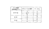
- Case 1 is a combination example in the above case.
- the oscillation operation may be performed on the drive shafts as in cases 2 and 3.
- the oscillation operation is performed for the movement of the measuring element 21 in the X-axis direction and the Y-axis direction (that is, the movement of the measuring element 21 in the direction of the tangent L of the base circle).
- the oscillation operation (repetitive operation of increasing / decreasing the rotation speed) is performed with respect to the rotation of the workpiece W around the C axis.
- the tooth surface Wa is applied to the measuring element 21.
- the oscillating operation for moving the touch probe 20 off by moving it in the direction away from the touch probe 20 that is, for receiving an OFF signal from the touch probe 20) is continuously performed.
- the base operation for moving the probe 21 along the ideal tooth profile line is performed by controlling the movement of the probe 21 in the X-axis direction and the rotation of the workpiece W around the C-axis. May be.
- the workpiece W is rotated around the C axis (base operation) in synchronism with the movement of the probe 21 of the touch probe 20 in the X axis direction (base operation) (tooth height direction measurement method).
- the measuring element 21 can be moved along an ideal tooth profile line.
- the oscillation operation is performed by the drive shaft as in the cases 4 and 5.
- Case 4 the oscillation operation is performed for the movement of the probe 21 in the Y-axis direction.
- the oscillation operation is performed with respect to the rotation of the workpiece W around the C axis.
- the base operation for moving the probe 21 along the ideal tooth profile line is performed by controlling the movement of the probe 21 in the Y-axis direction and the rotation of the workpiece W around the C-axis. May be.
- the workpiece W is rotated around the C axis (base operation) in synchronization with the movement of the probe 21 of the touch probe 20 in the Y axis direction (base operation) (basic circle tangential direction measurement method).
- the measuring element 21 can be moved along an ideal tooth profile line.
- the oscillation operation is performed by the drive shaft as in the cases 6 and 7.
- the oscillation operation is performed for the movement of the probe 21 in the Y-axis direction.
- the oscillation operation is performed with respect to the rotation of the workpiece W around the C axis.
- the amount of movement of the probe 21 in the Y axis direction is set to 0 (that is, the Y axis direction). It can be assumed that this is the case where the measuring element 21 is not moved.
- the amount of movement of the probe 21 in the X axis direction is set to 0 when the base operation is performed on the X, Y, C axes (that is, in the X axis direction). It can be assumed that this is the case where the measuring element 21 is not moved.
- the direction of tooth profile measurement as described above can be applied whether the workpiece W is a helical gear or a spur gear.
- the base operation is an operation for moving the probe 21 of the touch probe 20 along the ideal tooth line of the tooth surface Wa of the workpiece W.
- the oscillation operation is the same as in the case of the above tooth profile measurement.
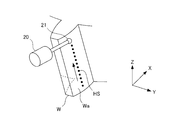
- the workpiece W is rotated around the C axis so that the tooth gap of the workpiece W is opposed to the probe 21 of the touch probe 20, and then the probe 21 is moved to the X, Y, and Z axes.
- the touch probe 20 is turned on in contact with the tooth trace measurement start point on the tooth surface Wa of the workpiece W. That is, the measuring element 21 is positioned at the starting point of the tooth trace measurement.
- the workpiece W is rotated around the C axis in synchronization with the movement of the probe 21 of the touch probe 20 in the Z axis direction.
- the measuring element 21 performs a base operation such that it moves along the ideal tooth trace line (target tooth trace shape) of the workpiece W.
- the measuring element 21 is also caused to perform an oscillation operation in the Y-axis direction.
- the touch probe 20 continuously performs ON / OFF switching for each measurement point by the oscillation operation while performing the base operation.
- FIG. 9A shows the movement (base operation) of the measuring element 21 in the Z-axis direction so that the measuring element 22 moves along the ideal tooth trace line.
- the vertical axis represents the position (coordinates) in the Z-axis direction
- the horizontal axis represents time.
- FIG. 9B shows the rotation of the workpiece W around the C axis (base operation) for causing the probe 22 to move along the ideal tooth line.
- the vertical axis represents the rotation angle around the C axis
- the horizontal axis represents time.
- an oscillating operation of the measuring element 21 in the Y-axis direction as shown in FIG. 9C is performed.
- the vertical axis represents the position (coordinates) in the Y-axis direction
- the horizontal axis represents time.
- the touch probe 20 When the oscillation operation is added to the base operation in this way, the touch probe 20 performs the oscillation operation in the Y-axis direction (that is, repeatedly increases and decreases the movement speed in the Y-axis direction) as shown in FIG. 9C.
- the ON / OFF switching operation is repeated at a cycle corresponding to the cycle of the oscillation operation. That is, during the base operation, after the probe 21 is brought into contact with the tooth surface Wa and the touch probe 20 is turned on (that is, after receiving the ON signal from the touch probe 20), the probe 21 is moved to the tooth surface.
- the oscillation operation for moving the touch probe 20 in the direction away from Wa to turn the touch probe 20 OFF (that is, for receiving the OFF signal from the touch probe 20) is continuously performed.
- the waveform of the oscillation operation is not limited to the sine curve, and may be any waveform that changes periodically, for example, a triangular waveform. .
- the period of the oscillation operation may be shortened. That is, it is possible to easily change the number of measurement points for measuring the streak simply by changing the cycle of the oscillation operation.
- the cycle of the oscillation operation is not necessarily limited to a fixed cycle such as the sine curve in the illustrated example, and may be changed as appropriate.
- the amplitude of the oscillation operation may be set in the tooth trace measurement in the same manner as in the above tooth profile measurement (see FIGS. 5A and 5B).
- the base operation for moving the tracing stylus 21 along the ideal tooth line by controlling the movement of the tracing stylus 21 in the Z-axis direction and the rotation of the workpiece W around the C-axis is not limited to this, and the base operation and the oscillation operation can be performed by combining other drive shafts. May be performed.
- the base operation for moving the probe 21 along the ideal tooth line is performed by controlling the movement of the probe 21 in the Z-axis direction, the X-axis direction, and the Y-axis direction. May be. That is, the measuring element 21 may be moved along the ideal tooth line by performing a base operation in the Z, X, and Y axis directions.
- the oscillation operation is performed by the drive shaft as in the cases 13 to 15. In case 13, the oscillation operation is performed for the movement of the probe 21 in the Y-axis direction. In case 14, the oscillation operation is performed for the movement of the probe 21 in the X and Y axis directions. In case 15, the oscillation operation is performed with respect to the rotation of the workpiece W around the C axis.
- the tooth trace measurement when the workpiece W is a helical gear as shown in FIG. 8 has been described.
- the present invention can also be applied to the measurement of a spur gear trace.
- the base movement can be moved along the ideal tooth line by simply moving the probe 21 of the touch probe 20 in the Z-axis direction (base movement).
- the oscillation operation may be performed.
- the probe 21 of the touch probe 20 is used in the gear measurement method for measuring the tooth profile or the streak of the workpiece W using the touch probe 20.
- the movement of the measuring element 21 and the rotation of the workpiece W are controlled to move along the ideal tooth profile line of the workpiece W, or the movement of the measuring element 21 and the rotation of the workpiece W are controlled or the movement of the measuring element 21 is controlled.
- the probe 21 is brought into contact with the tooth surface Wa of the workpiece W to be moved from the touch probe 20.
- the touch probe 20 After receiving the first signal (ON signal or OFF signal), the touch probe 20 is moved by moving the touch probe 20 in a direction in which the probe 21 is separated from the tooth surface Wa of the workpiece W. Oscillation signal for receiving the second signal (OFF signal or ON signal), or the first signal (ON signal or OFF signal) from the touch probe 20 by bringing the tooth surface Wa of the workpiece W into contact with the probe 21 After receiving the signal), the tooth surface Wa of the workpiece W is moved away from the measuring element 21, and the oscillation operation for receiving the second signal (OFF signal or ON signal) from the touch probe 20 is performed. Since the operation is performed continuously, the first signal and the second signal of the touch probe can be switched (ON / OFF switching) continuously by performing the oscillation operation while performing the base operation. it can.
- the time required for tooth profile measurement or tooth trace measurement can be greatly shortened.
- the movement along the ideal tooth profile / tooth trace line is set as the base action, but the movement is not necessarily limited to this, and the movement along the tooth profile / tooth trace line obtained by calculation may be set as the base action. . That is, the base movement is not necessarily movement along the ideal tooth profile / tooth line, but movement along any tooth profile / tooth line obtained by a computing device such as a personal computer is used as the base action.
- the tracing stylus may be moved along a different path from the tooth profile / tooth line. For example, before measuring the gear, when it is known beforehand that the tooth profile / tooth profile has a certain amount of inclination by simulation, etc., the ideal tooth profile / tooth line is equivalent to that inclination.
- the movement (movement) along the inclined tooth profile / tooth line may be given as the base movement.
- the same effect as in the case of an ideal tooth profile / tooth line is obtained. That is, in addition to the base operation for moving along the tooth profile / tooth line obtained by the calculation, the touch operation is performed while performing the base operation by continuously performing the oscillation operation during the base operation.
- the first signal and the second signal of the probe can be continuously switched (ON / OFF switching).
- the present invention relates to a gear measurement method, and is useful when applied to measurement of gear tooth profile and tooth trace using a touch probe.
- 11 gear measuring device 12 base, 13 guide rail, 14 rotating table, 15 moving body, 16 guide rail, 17 moving body, 18 guide rail, 19 moving body, 20 touch probe, 21 measuring element, 22 control arithmetic device , HG tooth profile, HS tooth trace, W work (gear), Wa tooth surface
Landscapes
- Physics & Mathematics (AREA)
- General Physics & Mathematics (AREA)
- Engineering & Computer Science (AREA)
- Mechanical Engineering (AREA)
- A Measuring Device Byusing Mechanical Method (AREA)
- Length Measuring Devices With Unspecified Measuring Means (AREA)
- Machine Tool Sensing Apparatuses (AREA)
- Testing Of Devices, Machine Parts, Or Other Structures Thereof (AREA)
Abstract
Description
このような歯車加工機によって歯車を加工する場合には、加工済みのロット中から抜き出した少なくとも1つの歯車に対し、歯車測定装置によって歯形や歯すじなどの歯車測定をした後、その加工精度を確認して、加工精度が良好である場合には引き続き歯車加工機で残りの未加工ロットを加工し、加工精度が不良である場合には歯車加工機の加工精度を修整してから、残りの未加工ロットを加工するようにしている。また、歯車が大形である場合には、不良品を出すことができないため、取り代を残しながら、歯車加工機による歯車加工と歯車測定装置による歯車測定とを数回繰り返し、最終的な精度を確認した後、仕上げ加工を行なうようにしている。
前記タッチ式プローブの測定子を、前記測定子の移動及び前記歯車の回転を制御し前記歯車の理想歯形ライン、又は、演算によって求められた歯形ラインに沿って移動させる、又は、前記測定子の移動及び前記歯車の回転を制御し若しくは前記測定子の移動を制御し前記歯車の理想歯すじライン、又は、演算によって求められた歯すじラインに沿って移動させるためのベース動作を行なうことに加えて、
前記ベース動作中に、前記測定子を前記歯車の歯面に当接させて前記タッチ式プローブからの第1信号を受け取った後、前記測定子が前記歯車の歯面に対し離間する方向へ前記タッチ式プローブを移動させて前記タッチ式プローブからの第2信号を受け取るためのオシレーション動作、又は、前記歯車の歯面を前記測定子に当接させて前記タッチ式プローブからの第1信号を受け取った後、前記歯車の歯面を前記測定子に対し離間する方向へ移動させて前記タッチ式プローブからの第2信号を受け取るためのオシレーション動作を連続して行なうこと、
を特徴とする。
前記歯車の歯形測定に関するものであり、
前記測定子を前記理想歯形ライン、又は、演算によって求められた歯形ラインに沿って移動させるための前記ベース動作は、前記歯車の回転中心に対して垂直なX軸方向、及び、前記X軸方向に対して垂直で且つ前記歯車の径方向に対して平行なY軸方向への前記測定子の移動と、前記回転中心と同軸なC軸回りの前記歯車の回転とを制御することにより、実施し、
前記オシレーション動作は、前記Y軸方向への前記測定子の移動と、前記X軸方向及び前記Y軸方向への前記測定子の移動と、前記C軸回り前記歯車の回転の何れか1つに対して実施すること、
を特徴とする。
前記ベース動作では、前記X軸方向への前記測定子の移動量又は前記Y軸方向への前記測定子の移動量を0とし、
前記オシレーション動作は、前記Y軸方向への前記測定子の移動と、前記C軸回り前記歯車の回転の何れかに対して実施すること、
を特徴とする。
前記歯車の歯すじ測定に関するものであり、
前記測定子を前記理想歯すじライン、又は、演算によって求められた歯すじラインに沿って移動させるための前記ベース動作は、前記歯車の回転中心に対して平行なZ軸方向への前記測定子の移動と、前記回転中心と同軸なC軸回りの前記歯車の回転とを制御することにより、実施し、或いは、前記Z軸方向、前記回転中心に対して垂直なX軸方向、及び、前記X軸方向に対して垂直で且つ前記歯車の径方向に対して平行なY軸方向への前記測定子の移動を制御することにより、実施し、
前記オシレーション動作は、前記Y軸方向への前記測定子の移動と、前記C軸回り前記歯車の回転の何れかに対して実施すること、或いは、前記Y軸方向への前記測定子の移動と、前記X軸方向及び前記Y軸方向への前記測定子の移動と、前記C軸回り前記歯車の回転の何れか1つに対して実施すること、
を特徴とする。
このため、従来の方法に比べて歯形測定又は歯すじ測定に要する時間を大幅に短縮することができる。しかも、オシレーション動作の周期を変更するだけで容易に測定点数を増やすことができ、測定点数を増やしても、従来のような多大な測定時間を要することはない。
まず、図1に基づき、本発明の実施の形態例に係る歯車測定方法を実施する歯車測定装置11の構成について説明する。なお、本発明の歯車測定方法は、歯車加工機に一体的に装備された歯車測定装置(機上の歯車測定装置)と、歯車加工機と別体の歯車測定装置の何れにも適用することができるものであるが、耐環境性に優れ且つ安価なタッチ式プローブを用いることから、特に機上の歯車測定装置に適しており、コスト低減を図ることもできる。
なお、X軸方向は、ワークWの回転中心に対して垂直な方向である。Y軸方向は、X軸方向に対して垂直で且つワークWの径方向に対して平行な方向である。Z軸方向は、ワークWの回転中心(即ちC軸)に対して平行な方向である。
なお、ここではタッチ式プローブ20の内部スイッチがa接点方式のものである場合について説明する。タッチ式プローブ20の内部スイッチがb接点方式のものである場合には、ONとOFFの関係がa接点方式の場合と逆になる。
即ち、制御演算装置22では、予め設定されて記憶しているワークWの歯車諸元、タッチ式プローブ20(測定子21)の位置(座標)、歯形測定位置、歯すじ測定位置などに基づいて、移動体15,17,19のX,Y,Z軸方向の移動を制御することにより、タッチ式プローブ20(測定子21)のX,Y,Z軸方向の移動を制御し、且つ、ワークWが載置された回転テーブル14のC軸回りの回転を制御する。
また、制御演算装置22では、タッチ式プローブ20からのON信号(第1信号)及びOFF信号(第2信号)を受け取り、前記ON信号を受け取ったときのX,Y,Z軸の座標やC軸回りの回転角度を取り込んで演算処理をすることにより、ワークWの歯形形状や歯すじ形状を求める。
次に、図1~図7に基づき、制御演算装置22による制御演算の下に、歯車測定装置11によって歯形測定を実施する場合の方法について説明する。
また、オシレーション動作とは、タッチ式プローブ20の測定子21をオシレーション(振動)させることにより、測定子21を歯面Waに当接させて(即ち測定子21を押し込んでプリトラベル量Δだけ変位させて)タッチ式プローブ20をONさせた後(即ちタッチ式プローブ20からのON信号を受け取った後)、測定子21が歯面Waに対し離間する方向へタッチ式プローブ20を移動させてタッチ式プローブ20をOFFさせること(即ちタッチ式プローブ20からのOFF信号を受け取ること)を連続して行うための動作、又は、ワークWをオシレーションさせることにより、歯面Waを測定子21に当接させて(即ち測定子21を押し込んでプリトラベル量Δだけ変位させて)タッチ式プローブ20をONさせた後(即ちタッチ式プローブ20からのON信号を受け取った後)、歯面Waを測定子21に対し離間させる方向へ移動させてタッチ式プローブ20をOFFさせること(即ちタッチ式プローブ20からのOFF信号を受け取ること)を連続して行うための動作である。
なお、タッチ式プローブ20をOFFにする際には、必ずしも測定子21と歯面Waが離れる必要はない。例えば測定子21が歯面Waに単に接触しているだけであれば、タッチ式プローブ20はOFFになる。従って、タッチ式プローブ20をON状態からOFF状態へ切り換えるには、上記の如く、測定子21が歯面Waに対し離間する方向へタッチ式プローブ20を移動させるか、又は、歯面Waを測定子21に対し離間させる方向へ移動させればよい。
そして、このベース動作中に、測定子21にはY軸方向のオシレーション動作も行わせる。その結果、タッチ式プローブ20はベース動作を行いつつ、オシレーション動作により各測定点ごとのON・OFFの切り換えを連続して行う。
また、歯形測定の精度を高めるために測定点数を増やす場合には、オシレーション動作の周期を短くすればよい。即ち、オシレーション動作の周期を変更するだけで容易に歯形測定のための測定点数を変更することができる。
更に、オシレーション動作の周期については、必ずしも図示例のサインカーブなどのような一定の周期に限定するものではなく、例えば歯元側と歯先側で異なる周期にするなど、適宜、変化させてもよい。
例えば、研削前や研削中のワークWの歯形測定においては、図5(a)に示すように試験結果や精度等級などから予測した比較的大きな誤差ε1よりも大きな(図示例ではε1の2倍の)振幅δ1を、オシレーション動作の振幅として設定し、研削後のワークWの歯形測定においては、図5(b)に示すように試験結果や精度等級などから予測した比較的小さな誤差ε2よりも大きな(図示例ではε2の2倍の)振幅δ2を、オシレーション動作の振幅として設定してもよい。
前者の場合には図6(a)に実線で例示すように、X,Y軸方向のベース動作にY軸方向のオシレーション動作を加えた場合の測定子21の軌跡が、比較的大きく変動するのに対して、後者の場合には図6(b)に実線で例示すように、X,Y軸方向のベース動作にY軸方向のオシレーション動作を加えた場合の測定子21の軌跡の変動が、比較的小さくなる。
そして、この場合にはケース4,5のような駆動軸によってオシレーション動作を実施する。ケース4では、Y軸方向への測定子21の移動に対してオシレーション動作を実施する。ケース5では、C軸回りのワークWの回転に対してオシレーション動作を実施する。
そして、この場合にはケース6,7のような駆動軸によってオシレーション動作を行なう。ケース6では、Y軸方向への測定子21の移動に対してオシレーション動作を実施する。ケース7では、C軸回りのワークWの回転に対してオシレーション動作を実施する。
次に、図8~図10に基づき、制御演算装置22による制御演算の下に、歯車測定装置11によって歯すじ測定を実施する場合の方法について説明する。
ここでベース動作とは、タッチ式プローブ20の測定子21を、ワークWの歯面Waの理想歯すじラインに沿って移動させるための動作である。
また、オシレーション動作については、上記の歯形測定の場合と同様である。
また、歯すじ測定の精度を高めるために測定点数を増やす場合には、オシレーション動作の周期を短くすればよい。即ち、オシレーション動作の周期を変更するだけで容易に歯すじ測定のための測定点数を変更することができる。
オシレーション動作の周期については、必ずしも図示例のサインカーブなどのような一定の周期に限定するものではなく、適宜、変化させてもよい。
更に、オシレーション動作の振幅に関しては、歯すじ測定においても、上記の歯形測定の場合と同様に設定すればよい(図5(a),(b)を参照)。
この他、Z,C軸でベース動作を行う場合には、ケース12のような駆動軸によってオシレーション動作を行なうようにしてもよい。ケース12では、ワークWのC軸回りの回転に対してオシレーション動作(回転速度の増減の繰り返し)を実施する。この場合には、歯面Waを測定子21に当接させてタッチ式プローブ20をONさせた後(即ちタッチ式プローブ20からのON信号を受け取った後)、歯面Waを測定子21に対し離間させる方向へ移動させてタッチ式プローブ20をOFFさせるため(即ちタッチ式プローブ20からのOFF信号を受け取るため)のオシレーション動作が連続して行なわれる。
そして、この場合にはケース13~15のような駆動軸によってオシレーション動作を行なう。ケース13では、Y軸方向への測定子21の移動に対してオシレーション動作を実施する。ケース14では、X,Y軸方向への測定子21の移動に対してオシレーション動作を実施する。ケース15では、C軸回りのワークWの回転に対してオシレーション動作を実施する。
このため、従来の方法に比べて歯形測定又は歯すじ測定に要する時間を大幅に短縮することができる。しかも、オシレーション動作の周期を変更するだけで容易に測定点数を増やすことができ、測定点数を増やしても、従来のような多大な測定時間を要することはない。
即ち、ベース動作は、必ずしも理想の歯形/歯すじラインに沿う移動であるとは限らず、パソコンなどの演算装置によって求められた任意の歯形/歯すじラインに沿う移動をベース動作とし、理想の歯形/歯すじラインとは異なる軌跡で測定子を動かすこともある。
例えば、歯車を測定する前に、シミュレーションなどによって、歯形/歯すじ形状に一定量の傾きがあることが予め分っているときなどは、その傾き分だけ理想の歯形/歯すじラインに対して傾斜させた歯形/歯すじラインに沿う動作(移動)を、ベース動作として与えることもある。
この場合にも、理想の歯形/歯すじラインの場合と同様の効果が得られる。即ち、演算によって求められた歯形/歯すじラインに沿って移動させるためのベース動作に加えて、このベース動作中に、オシレーション動作を連続して行なうことより、ベース動作を行いつつ、タッチ式プローブの第1信号と第2信号の切り換え(ON・OFF切り換え)を連続的に行なうことができる。
Claims (4)
- タッチ式プローブを用いて歯車の歯形又は歯すじの測定を行なう歯車測定方法において、
前記タッチ式プローブの測定子を、前記測定子の移動及び前記歯車の回転を制御し前記歯車の理想歯形ライン、又は、演算によって求められた歯形ラインに沿って移動させる、又は、前記測定子の移動及び前記歯車の回転を制御し若しくは前記測定子の移動を制御し前記歯車の理想歯すじライン、又は、演算によって求められた歯すじラインに沿って移動させるためのベース動作を行なうことに加えて、
前記ベース動作中に、前記測定子を前記歯車の歯面に当接させて前記タッチ式プローブからの第1信号を受け取った後、前記測定子が前記歯車の歯面に対し離間する方向へ前記タッチ式プローブを移動させて前記タッチ式プローブからの第2信号を受け取るためのオシレーション動作、又は、前記歯車の歯面を前記測定子に当接させて前記タッチ式プローブからの第1信号を受け取った後、前記歯車の歯面を前記測定子に対し離間する方向へ移動させて前記タッチ式プローブからの第2信号を受け取るためのオシレーション動作を連続して行なうこと、
を特徴とする歯車測定方法。 - 請求項1に記載の歯車測定方法において、
前記歯車の歯形測定に関するものであり、
前記測定子を前記理想歯形ライン、又は、演算によって求められた歯形ラインに沿って移動させるための前記ベース動作は、前記歯車の回転中心に対して垂直なX軸方向、及び、前記X軸方向に対して垂直で且つ前記歯車の径方向に対して平行なY軸方向への前記測定子の移動と、前記回転中心と同軸なC軸回りの前記歯車の回転とを制御することにより、実施し、
前記オシレーション動作は、前記Y軸方向への前記測定子の移動と、前記X軸方向及び前記Y軸方向への前記測定子の移動と、前記C軸回り前記歯車の回転の何れか1つに対して実施すること、
を特徴とする歯車測定方法。 - 請求項2に記載の歯車測定方法において、
前記ベース動作では、前記X軸方向への前記測定子の移動量又は前記Y軸方向への前記測定子の移動量を0とし、
前記オシレーション動作は、前記Y軸方向への前記測定子の移動と、前記C軸回り前記歯車の回転の何れかに対して実施すること、
を特徴とする歯車測定方法。 - 請求項1に記載の歯車測定方法において、
前記歯車の歯すじ測定に関するものであり、
前記測定子を前記理想歯すじライン、又は、演算によって求められた歯すじラインに沿って移動させるための前記ベース動作は、前記歯車の回転中心に対して平行なZ軸方向への前記測定子の移動と、前記回転中心と同軸なC軸回りの前記歯車の回転とを制御することにより、実施し、或いは、前記Z軸方向、前記回転中心に対して垂直なX軸方向、及び、前記X軸方向に対して垂直で且つ前記歯車の径方向に対して平行なY軸方向への前記測定子の移動を制御することにより、実施し、
前記オシレーション動作は、前記Y軸方向への前記測定子の移動と、前記C軸回り前記歯車の回転の何れかに対して実施すること、或いは、前記Y軸方向への前記測定子の移動と、前記X軸方向及び前記Y軸方向への前記測定子の移動と、前記C軸回り前記歯車の回転の何れか1つに対して実施すること、
を特徴とする歯車測定方法。
Priority Applications (4)
| Application Number | Priority Date | Filing Date | Title |
|---|---|---|---|
| EP10839029.5A EP2518435A4 (en) | 2009-12-22 | 2010-09-15 | Gear measuring method |
| CN201080054444.3A CN102639957B (zh) | 2009-12-22 | 2010-09-15 | 齿轮测定方法 |
| BR112012013065A BR112012013065A2 (pt) | 2009-12-22 | 2010-09-15 | método de medição de engrenagem. |
| US13/512,608 US8991246B2 (en) | 2009-12-22 | 2010-09-15 | Gear measuring method |
Applications Claiming Priority (2)
| Application Number | Priority Date | Filing Date | Title |
|---|---|---|---|
| JP2009-290330 | 2009-12-22 | ||
| JP2009290330A JP5439157B2 (ja) | 2009-12-22 | 2009-12-22 | 歯車測定方法 |
Publications (1)
| Publication Number | Publication Date |
|---|---|
| WO2011077792A1 true WO2011077792A1 (ja) | 2011-06-30 |
Family
ID=44195340
Family Applications (1)
| Application Number | Title | Priority Date | Filing Date |
|---|---|---|---|
| PCT/JP2010/065912 Ceased WO2011077792A1 (ja) | 2009-12-22 | 2010-09-15 | 歯車測定方法 |
Country Status (7)
| Country | Link |
|---|---|
| US (1) | US8991246B2 (ja) |
| EP (1) | EP2518435A4 (ja) |
| JP (1) | JP5439157B2 (ja) |
| CN (1) | CN102639957B (ja) |
| BR (1) | BR112012013065A2 (ja) |
| TW (1) | TWI425186B (ja) |
| WO (1) | WO2011077792A1 (ja) |
Cited By (1)
| Publication number | Priority date | Publication date | Assignee | Title |
|---|---|---|---|---|
| WO2013117558A1 (de) * | 2012-02-06 | 2013-08-15 | Deckel Maho Pfronten Gmbh | Numerisch gesteuerte werkzeugmaschine und verfahren zum steuern eines automatischen rotatorischen ausrichtvorgangs eines zahnrads an der werkzeugmaschine |
Families Citing this family (24)
| Publication number | Priority date | Publication date | Assignee | Title |
|---|---|---|---|---|
| CN102216726A (zh) * | 2009-04-24 | 2011-10-12 | 株式会社东京技术 | 渐开线齿轮齿廓测量方法 |
| DE102010023728A1 (de) * | 2010-06-14 | 2011-12-15 | Liebherr-Verzahntechnik Gmbh | Verfahren zum Herstellen einer Mehrzahl von identischen Zahnrädern mittles abspanender Bearbeitung |
| US9146089B2 (en) * | 2011-06-20 | 2015-09-29 | Marposs Societa' Per Azioni | Method and apparatus for measuring a manufacturing deviation in an external gear |
| WO2013156767A1 (en) * | 2012-04-18 | 2013-10-24 | Renishaw Plc | A method of finding a feature using a machine tool |
| US10037017B2 (en) * | 2012-04-18 | 2018-07-31 | Renishaw Plc | Method of measurement on a machine tool and corresponding machine tool apparatus |
| US9726481B2 (en) | 2012-04-18 | 2017-08-08 | Renishaw Plc | Method of analogue measurement scanning on a machine tool |
| DE102013207116B4 (de) * | 2013-04-19 | 2019-01-31 | Carl Zeiss Industrielle Messtechnik Gmbh | Koordinatenmessgerät und Verfahren zur Steuerung eines Koordinatenmessgeräts |
| CN103769692B (zh) * | 2014-02-18 | 2016-06-15 | 南京工业大学 | 大型齿轮齿距偏差在机测量装置和方法 |
| US9752860B2 (en) * | 2015-07-14 | 2017-09-05 | Caterpillar Inc. | System and method for gear measurement |
| JP6537915B2 (ja) * | 2015-07-27 | 2019-07-03 | Ntn株式会社 | ピッチ円錐角測定方法及び測定装置 |
| EP3315896B1 (en) * | 2015-08-27 | 2020-03-04 | Tokyo Seimitsu Co., Ltd. | Surface shape measuring device and method |
| CN105698722A (zh) * | 2016-01-21 | 2016-06-22 | 深圳市海翔铭实业有限公司 | 一种齿轮精度测量、评价的方法 |
| US10288404B2 (en) * | 2016-04-06 | 2019-05-14 | Jtekt Corporation | Gear measurement method and gear measurement apparatus |
| KR20170120312A (ko) * | 2016-04-21 | 2017-10-31 | (주)로보티즈 | 사이클로이드 기어의 치형 측정 장치 및 방법 |
| EP3255373B1 (de) | 2016-06-09 | 2019-04-24 | Klingelnberg AG | Berührungsmessung an der zahnflanke eines zahnradbauteils |
| CN108020594A (zh) * | 2016-11-04 | 2018-05-11 | 韩虎产业株式会社 | 齿轮部件的表面缺陷检查装置 |
| CN106767636B (zh) * | 2017-01-17 | 2019-04-23 | 江苏科技大学 | 采用三坐标测量机测量小型直齿圆柱齿轮外径的方法 |
| CN107101570B (zh) * | 2017-06-06 | 2019-07-05 | 哈尔滨精达测量仪器有限公司 | 一种齿轮测量中心的直角校准块布局方法、坐标标定方法和坐标调整方法 |
| CN107990824A (zh) * | 2017-11-20 | 2018-05-04 | 东莞市鑫拓智能机械科技有限公司 | 一种谐波减速器齿形跳动检测设备 |
| DE102018112805A1 (de) * | 2018-05-29 | 2019-12-05 | Klingelnberg Gmbh | Verfahren zur Analyse von Oberflächenwelligkeiten |
| DE102019104891B3 (de) * | 2019-02-26 | 2020-03-12 | Liebherr-Verzahntechnik Gmbh | Verfahren zum Kalibrieren eines Messtasters in einer Verzahnmaschine |
| JP7236952B2 (ja) * | 2019-07-29 | 2023-03-10 | 株式会社ミツトヨ | 形状測定装置、及び形状測定方法 |
| CN111015363A (zh) * | 2019-12-27 | 2020-04-17 | 四川职业技术学院 | 一种机械加工用快速定位装置 |
| WO2023044850A1 (zh) * | 2021-09-26 | 2023-03-30 | 大连理工大学 | 一种连轴装配式大齿轮渐开线样板 |
Citations (3)
| Publication number | Priority date | Publication date | Assignee | Title |
|---|---|---|---|---|
| JPH05111851A (ja) | 1991-10-24 | 1993-05-07 | Sumitomo Heavy Ind Ltd | 歯車測定方法および歯車測定兼用歯車研削盤 |
| JPH10300455A (ja) * | 1997-03-21 | 1998-11-13 | Carl Zeiss:Fa | 座標測定装置を目標データに従って制御する方法 |
| JP2007279012A (ja) * | 2006-03-16 | 2007-10-25 | Mitsutoyo Corp | 表面性状測定装置 |
Family Cites Families (19)
| Publication number | Priority date | Publication date | Assignee | Title |
|---|---|---|---|---|
| US5136527A (en) * | 1990-10-05 | 1992-08-04 | Precision Devices, Inc. | Surface finish measuring device and method for gear teeth |
| JP3069931B2 (ja) * | 1992-03-16 | 2000-07-24 | 科学技術振興事業団 | 表面形状測定方法及び装置 |
| US5343626A (en) * | 1993-01-26 | 1994-09-06 | Sumitomo Heavy Industries, Ltd. | Method for measuring gears and system for machining and measuring gears |
| DE4336267A1 (de) * | 1993-10-23 | 1995-04-27 | Perthen Feinpruef Gmbh | Verfahren zur Messung eines Werkstückprofils |
| JPH08285512A (ja) * | 1995-04-12 | 1996-11-01 | Matsushita Electric Ind Co Ltd | 微細表面形状測定装置 |
| US5918274A (en) * | 1997-06-02 | 1999-06-29 | International Business Machines Corporation | Detecting fields with a single-pass, dual-amplitude-mode scanning force microscope |
| US6079254A (en) * | 1998-05-04 | 2000-06-27 | International Business Machines Corporation | Scanning force microscope with automatic surface engagement and improved amplitude demodulation |
| DE10016070B4 (de) * | 1999-04-02 | 2019-04-18 | Mitutoyo Corporation | Bewegungssteuervorrichtung einer Schwingsonde eines Kontakttyps |
| JP4399052B2 (ja) * | 1999-04-02 | 2010-01-13 | 株式会社ミツトヨ | タッチ信号プローブの動作制御構造 |
| JP4399053B2 (ja) * | 1999-04-08 | 2010-01-13 | 株式会社ミツトヨ | タッチ信号プローブの動作制御構造 |
| DE10035714B4 (de) * | 1999-07-23 | 2011-06-09 | Mitutoyo Corp. | Oberflächengestalt-Messverfahren |
| JP3536013B2 (ja) * | 1999-07-23 | 2004-06-07 | 株式会社ミツトヨ | 表面形状測定方法 |
| JP3961258B2 (ja) * | 2001-10-10 | 2007-08-22 | 株式会社ミツトヨ | タッチセンサ、および微細形状測定装置用プローブ |
| JP4009152B2 (ja) * | 2002-07-09 | 2007-11-14 | 株式会社ミツトヨ | 表面形状測定装置および表面形状測定方法 |
| WO2006073068A1 (ja) * | 2005-01-06 | 2006-07-13 | National University Corporation Hokkaido University | 表面位置計測方法および表面位置計測装置 |
| JP4909548B2 (ja) * | 2005-09-01 | 2012-04-04 | 株式会社ミツトヨ | 表面形状測定装置 |
| JP2007309684A (ja) * | 2006-05-16 | 2007-11-29 | Mitsutoyo Corp | 測定制御装置、表面性状測定装置、および、測定制御方法 |
| US7814779B2 (en) * | 2006-06-06 | 2010-10-19 | Mitutoyo Corporation | Surface texture measuring instrument |
| JP5091702B2 (ja) * | 2008-02-04 | 2012-12-05 | 株式会社ミツトヨ | プローブの真直度測定方法 |
-
2009
- 2009-12-22 JP JP2009290330A patent/JP5439157B2/ja active Active
-
2010
- 2010-09-15 US US13/512,608 patent/US8991246B2/en active Active
- 2010-09-15 CN CN201080054444.3A patent/CN102639957B/zh active Active
- 2010-09-15 BR BR112012013065A patent/BR112012013065A2/pt not_active IP Right Cessation
- 2010-09-15 WO PCT/JP2010/065912 patent/WO2011077792A1/ja not_active Ceased
- 2010-09-15 EP EP10839029.5A patent/EP2518435A4/en not_active Withdrawn
- 2010-09-28 TW TW099132827A patent/TWI425186B/zh active
Patent Citations (3)
| Publication number | Priority date | Publication date | Assignee | Title |
|---|---|---|---|---|
| JPH05111851A (ja) | 1991-10-24 | 1993-05-07 | Sumitomo Heavy Ind Ltd | 歯車測定方法および歯車測定兼用歯車研削盤 |
| JPH10300455A (ja) * | 1997-03-21 | 1998-11-13 | Carl Zeiss:Fa | 座標測定装置を目標データに従って制御する方法 |
| JP2007279012A (ja) * | 2006-03-16 | 2007-10-25 | Mitsutoyo Corp | 表面性状測定装置 |
Non-Patent Citations (1)
| Title |
|---|
| See also references of EP2518435A4 |
Cited By (1)
| Publication number | Priority date | Publication date | Assignee | Title |
|---|---|---|---|---|
| WO2013117558A1 (de) * | 2012-02-06 | 2013-08-15 | Deckel Maho Pfronten Gmbh | Numerisch gesteuerte werkzeugmaschine und verfahren zum steuern eines automatischen rotatorischen ausrichtvorgangs eines zahnrads an der werkzeugmaschine |
Also Published As
| Publication number | Publication date |
|---|---|
| US20120247199A1 (en) | 2012-10-04 |
| BR112012013065A2 (pt) | 2016-11-22 |
| EP2518435A4 (en) | 2017-10-11 |
| JP2011133237A (ja) | 2011-07-07 |
| JP5439157B2 (ja) | 2014-03-12 |
| US8991246B2 (en) | 2015-03-31 |
| CN102639957A (zh) | 2012-08-15 |
| CN102639957B (zh) | 2015-05-20 |
| TW201131140A (en) | 2011-09-16 |
| EP2518435A1 (en) | 2012-10-31 |
| TWI425186B (zh) | 2014-02-01 |
Similar Documents
| Publication | Publication Date | Title |
|---|---|---|
| JP5439157B2 (ja) | 歯車測定方法 | |
| CN110398938B (zh) | 显示装置 | |
| CN102782441B (zh) | 齿轮测量装置的校正方法 | |
| CN102821900B (zh) | 齿轮磨床及齿轮磨削方法 | |
| JP2010117196A (ja) | 歯車測定方法 | |
| CN108873804A (zh) | 用于摆动切削的显示装置以及加工系统 | |
| CN101419066B (zh) | 一种两轴随动控制检测齿轮齿廓和螺旋线的方法 | |
| EP3510351B1 (en) | Measurement of toothed articles utilizing multiple sensors | |
| JPWO2010122680A1 (ja) | インボリュート歯車の歯形測定方法 | |
| CN115210023B (zh) | 用于加工具有两个齿部的工件的方法、用于确定工件的参考转动角位置的定位装置和具有这种定位装置的机床 | |
| CN104154849B (zh) | 基于三轴联动的复杂零件准测量中心路径规划实现方法及装置 | |
| CN108213744B (zh) | 一种基于工控机的激光微孔加工协同控制系统及其方法 | |
| CN112798270A (zh) | 一种渐开螺旋圆柱齿轮的法向啮合齿形测量方法 | |
| CN100424602C (zh) | 伺服控制装置以及伺服系统的调整方法 | |
| CN115519267B (zh) | 一种切割圆的方法及装置 | |
| JP3127785B2 (ja) | 歯車の歯形測定装置 | |
| Lin et al. | A five-axis CNC machining method of orthogonal variable transmission ratio face gear | |
| JP2006349388A (ja) | 回転中心の測定方法および測定装置 | |
| CN113840688A (zh) | 位置关系测定方法、接触检测方法和加工装置 | |
| JP3072693B2 (ja) | 歯車形状の測定方法 | |
| JP2002178224A (ja) | 歯車における歯面の加工方法 | |
| CA3034633C (en) | Measurement of toothed articles utilizing multiple sensors | |
| JPH08210802A (ja) | はすば歯車の測定方式 | |
| CN121916768A (zh) | 具有轴线运动的光学测量 | |
| Pfeifer et al. | Measurement of Gearing Deviations with Large Gears in the Gear Cutting Machine |
Legal Events
| Date | Code | Title | Description |
|---|---|---|---|
| WWE | Wipo information: entry into national phase |
Ref document number: 201080054444.3 Country of ref document: CN |
|
| 121 | Ep: the epo has been informed by wipo that ep was designated in this application |
Ref document number: 10839029 Country of ref document: EP Kind code of ref document: A1 |
|
| WWE | Wipo information: entry into national phase |
Ref document number: 2010839029 Country of ref document: EP |
|
| WWE | Wipo information: entry into national phase |
Ref document number: 1282/MUMNP/2012 Country of ref document: IN |
|
| WWE | Wipo information: entry into national phase |
Ref document number: 13512608 Country of ref document: US |
|
| NENP | Non-entry into the national phase |
Ref country code: DE |
|
| WWE | Wipo information: entry into national phase |
Ref document number: 1201002553 Country of ref document: TH |
|
| REG | Reference to national code |
Ref country code: BR Ref legal event code: B01A Ref document number: 112012013065 Country of ref document: BR |
|
| ENP | Entry into the national phase |
Ref document number: 112012013065 Country of ref document: BR Kind code of ref document: A2 Effective date: 20120530 |