WO2011078035A1 - タービンハウジング - Google Patents
タービンハウジング Download PDFInfo
- Publication number
- WO2011078035A1 WO2011078035A1 PCT/JP2010/072584 JP2010072584W WO2011078035A1 WO 2011078035 A1 WO2011078035 A1 WO 2011078035A1 JP 2010072584 W JP2010072584 W JP 2010072584W WO 2011078035 A1 WO2011078035 A1 WO 2011078035A1
- Authority
- WO
- WIPO (PCT)
- Prior art keywords
- turbine
- sheet metal
- turbine rotor
- downstream
- turbine housing
- Prior art date
- Legal status (The legal status is an assumption and is not a legal conclusion. Google has not performed a legal analysis and makes no representation as to the accuracy of the status listed.)
- Ceased
Links
Images





Classifications
-
- F—MECHANICAL ENGINEERING; LIGHTING; HEATING; WEAPONS; BLASTING
- F02—COMBUSTION ENGINES; HOT-GAS OR COMBUSTION-PRODUCT ENGINE PLANTS
- F02C—GAS-TURBINE PLANTS; AIR INTAKES FOR JET-PROPULSION PLANTS; CONTROLLING FUEL SUPPLY IN AIR-BREATHING JET-PROPULSION PLANTS
- F02C6/00—Plural gas-turbine plants; Combinations of gas-turbine plants with other apparatus; Adaptations of gas-turbine plants for special use
- F02C6/04—Gas-turbine plants providing heated or pressurised working fluid for other apparatus, e.g. without mechanical power output
- F02C6/10—Gas-turbine plants providing heated or pressurised working fluid for other apparatus, e.g. without mechanical power output supplying working fluid to a user, e.g. a chemical process, which returns working fluid to a turbine of the plant
- F02C6/12—Turbochargers, i.e. plants for augmenting mechanical power output of internal-combustion piston engines by increase of charge pressure
-
- F—MECHANICAL ENGINEERING; LIGHTING; HEATING; WEAPONS; BLASTING
- F01—MACHINES OR ENGINES IN GENERAL; ENGINE PLANTS IN GENERAL; STEAM ENGINES
- F01D—NON-POSITIVE DISPLACEMENT MACHINES OR ENGINES, e.g. STEAM TURBINES
- F01D17/00—Regulating or controlling by varying flow
- F01D17/10—Final actuators
- F01D17/12—Final actuators arranged in stator parts
- F01D17/14—Final actuators arranged in stator parts varying effective cross-sectional area of nozzles or guide conduits
- F01D17/16—Final actuators arranged in stator parts varying effective cross-sectional area of nozzles or guide conduits by means of nozzle vanes
- F01D17/165—Final actuators arranged in stator parts varying effective cross-sectional area of nozzles or guide conduits by means of nozzle vanes for radial flow, i.e. the vanes turning around axes which are essentially parallel to the rotor centre line
-
- F—MECHANICAL ENGINEERING; LIGHTING; HEATING; WEAPONS; BLASTING
- F01—MACHINES OR ENGINES IN GENERAL; ENGINE PLANTS IN GENERAL; STEAM ENGINES
- F01D—NON-POSITIVE DISPLACEMENT MACHINES OR ENGINES, e.g. STEAM TURBINES
- F01D25/00—Component parts, details, or accessories, not provided for in, or of interest apart from, other groups
- F01D25/16—Arrangement of bearings; Supporting or mounting bearings in casings
-
- F—MECHANICAL ENGINEERING; LIGHTING; HEATING; WEAPONS; BLASTING
- F01—MACHINES OR ENGINES IN GENERAL; ENGINE PLANTS IN GENERAL; STEAM ENGINES
- F01D—NON-POSITIVE DISPLACEMENT MACHINES OR ENGINES, e.g. STEAM TURBINES
- F01D25/00—Component parts, details, or accessories, not provided for in, or of interest apart from, other groups
- F01D25/24—Casings; Casing parts, e.g. diaphragms, casing fastenings
-
- F—MECHANICAL ENGINEERING; LIGHTING; HEATING; WEAPONS; BLASTING
- F01—MACHINES OR ENGINES IN GENERAL; ENGINE PLANTS IN GENERAL; STEAM ENGINES
- F01D—NON-POSITIVE DISPLACEMENT MACHINES OR ENGINES, e.g. STEAM TURBINES
- F01D9/00—Stators
- F01D9/02—Nozzles; Nozzle boxes; Stator blades; Guide conduits, e.g. individual nozzles
- F01D9/026—Scrolls for radial machines or engines
-
- F—MECHANICAL ENGINEERING; LIGHTING; HEATING; WEAPONS; BLASTING
- F02—COMBUSTION ENGINES; HOT-GAS OR COMBUSTION-PRODUCT ENGINE PLANTS
- F02B—INTERNAL-COMBUSTION PISTON ENGINES; COMBUSTION ENGINES IN GENERAL
- F02B37/00—Engines characterised by provision of pumps driven at least for part of the time by exhaust
- F02B37/12—Control of the pumps
- F02B37/24—Control of the pumps by using pumps or turbines with adjustable guide vanes
-
- F—MECHANICAL ENGINEERING; LIGHTING; HEATING; WEAPONS; BLASTING
- F02—COMBUSTION ENGINES; HOT-GAS OR COMBUSTION-PRODUCT ENGINE PLANTS
- F02B—INTERNAL-COMBUSTION PISTON ENGINES; COMBUSTION ENGINES IN GENERAL
- F02B39/00—Component parts, details, or accessories relating to, driven charging or scavenging pumps, not provided for in groups F02B33/00 - F02B37/00
-
- F—MECHANICAL ENGINEERING; LIGHTING; HEATING; WEAPONS; BLASTING
- F05—INDEXING SCHEMES RELATING TO ENGINES OR PUMPS IN VARIOUS SUBCLASSES OF CLASSES F01-F04
- F05D—INDEXING SCHEME FOR ASPECTS RELATING TO NON-POSITIVE-DISPLACEMENT MACHINES OR ENGINES, GAS-TURBINES OR JET-PROPULSION PLANTS
- F05D2220/00—Application
- F05D2220/40—Application in turbochargers
-
- F—MECHANICAL ENGINEERING; LIGHTING; HEATING; WEAPONS; BLASTING
- F05—INDEXING SCHEMES RELATING TO ENGINES OR PUMPS IN VARIOUS SUBCLASSES OF CLASSES F01-F04
- F05D—INDEXING SCHEME FOR ASPECTS RELATING TO NON-POSITIVE-DISPLACEMENT MACHINES OR ENGINES, GAS-TURBINES OR JET-PROPULSION PLANTS
- F05D2230/00—Manufacture
- F05D2230/60—Assembly methods
- F05D2230/64—Assembly methods using positioning or alignment devices for aligning or centring, e.g. pins
-
- F—MECHANICAL ENGINEERING; LIGHTING; HEATING; WEAPONS; BLASTING
- F05—INDEXING SCHEMES RELATING TO ENGINES OR PUMPS IN VARIOUS SUBCLASSES OF CLASSES F01-F04
- F05D—INDEXING SCHEME FOR ASPECTS RELATING TO NON-POSITIVE-DISPLACEMENT MACHINES OR ENGINES, GAS-TURBINES OR JET-PROPULSION PLANTS
- F05D2260/00—Function
- F05D2260/96—Preventing, counteracting or reducing vibration or noise
Definitions
- the present invention relates to a sheet metal turbine housing that is used in a turbocharger that generates supercharging pressure for an engine using the energy of exhaust gas of the engine, and in particular, a bearing base side member that constitutes a core portion of the turbine housing, and
- the present invention relates to a strut structure that connects a member on the outlet flange side.
- the turbine housing has a large heat capacity, and if it is installed upstream of the exhaust purification catalyst, it will hinder catalyst warm-up. From the viewpoint of strengthening exhaust gas regulations in recent years, reducing the heat capacity by reducing the thickness and weight of the housing with sheet metal is important for activating the catalyst and improving the catalyst purification performance.
- the sheet metal part When adopting a sheet metal turbine housing, the sheet metal part is thin and weak in strength. Therefore, a member on the bearing housing side where a bearing supporting the rotating shaft of the turbine rotor blade is disposed, a member on the exhaust gas channel outlet side, The support
- the struts are provided on the outer peripheral side of the turbine rotor blades so as to cross the flow path flowing into the turbine rotor blades, the gas flow is hindered by the struts, leading to a decrease in turbine efficiency and a decrease in turbocharger performance. It was.
- Patent Document 1 Japanese Patent Publication No. 2006-527322
- an exhaust gas turbine 02 has an outer shell 03 covering the outside.
- a housing 04 having a scroll shape is provided inside, and an adjustable guide vane bearing ring 05 and a molding casing 07 on the outlet side of the flow path are connected in the housing 04 between them.
- a structure in which a spacer 01 is provided is shown. This spacer is installed so as to cross the radial inflow passage 09 to the turbine rotor blade.
- Patent Document 2 Japanese Patent Laid-Open No. 2008-57448
- Patent Document 3 Japanese Patent Publication No. 2003-536209
- Patent Document 1 shows how the spacers 01 shown in Patent Document 1 are arranged in the circumferential direction or what cross-sectional shape is formed with respect to the exhaust gas flowing through the flow path.
- Patent Documents 2 and 3 show that the scroll portion of a sheet metal turbine housing is welded in the circumferential direction by abutting two left and right sheet metal members, but the center side of the scroll portion.
- the structure of the core portion that forms the shaft portion of the strut portion that connects and fixes the member on the bearing housing side where the bearing supporting the rotating shaft of the turbine rotor blade is disposed and the member on the exhaust gas passage outlet side is connected. The structure is not shown.
- the strut is provided on the outer peripheral side of the turbine blade so as to cross the flow path flowing into the turbine rotor blade, it is desirable to make it as thin as possible in order to reduce the flow resistance.
- a certain strength is required from the viewpoint of connecting and fixing the member on the bearing housing side and the member on the exhaust gas channel outlet side.
- pressure fluctuations in the circumferential direction of the inflowing gas are caused by a plurality of support columns arranged in the circumferential direction, thereby generating an excitation force of a pressure wave, and when the excitation force resonates with the natural vibration of the turbine blade, the turbine blade There is a problem that hinders reliability. For this reason, it is necessary to set the arrangement
- a turbine housing blade includes a bearing housing side member in which a bearing that supports the rotating shaft of the turbine blade is disposed and an exhaust gas passage outlet side member.
- the flow resistance is reduced to improve the inflow characteristics, and the turbine blade resonance is avoided by reducing the resonance of the turbine blade. It is an object to improve reliability and reliability.
- the present invention provides a rotating shaft of a turbine rotor blade in a sheet metal turbine housing in which a scroll portion forming a spiral exhaust gas passage is formed by facing and joining a sheet metal scroll member.
- a plurality of columns in the circumferential direction on the outer peripheral side of the turbine rotor blade are connected to the bearing housing side member in which the bearing to be supported and the flow path outlet side member forming the outside of the turbine rotor blade are connected in the turbine axial direction.
- the gist is that this interval was provided.
- each column in the axial direction of the turbine is formed so that the upstream corner and the downstream corner of the gas flow are acute angles, and the upstream side surface and the downstream side surface are along the gas flow. It is characterized by being inclined.
- the bearing housing-side member in which the bearing that supports the rotating shaft of the turbine rotor blade is disposed, and the channel outlet-side member that forms the outside of the turbine rotor blade are provided by the support column. It is connected in the turbine axial direction, and the cross-sectional shape of the column in the turbine axial direction is formed so that the upstream corner and the downstream corner of the gas flow are acute angles, and the upstream side surface and the downstream side surface are along the gas flow. Therefore, both the projected area on the upstream side of the support column and the projected area on the downstream side can be reduced with respect to the gas flow toward the center side while turning the scroll part. It is possible to reduce road resistance and wake (flow distortion) generated behind the support column. As a result, it is possible to improve the flow distortion of the wake behind the strut and to improve the efficiency and reliability of the turbine rotor blade.
- the cross-sectional area of the strut is rigid enough to connect the member on the bearing housing side and the member on the outlet side of the flow path that forms the outside of the turbine blade, and to maintain a constant gap with the turbine blade. It has a cross-sectional area necessary to ensure strength.
- angles of the upstream corner and the downstream corner of the cross-sectional shape of the column may be 20 ° to 70 °. By setting such an acute angle, it is possible to ensure the column cross-sectional area and gas. It is possible to achieve both reduction of flow pressure loss.
- the cross-sectional shape of the support column may be a substantially square shape having an inscribed arc, a circumscribed arc, an upstream side surface, and a downstream side surface, or a substantially triangular shape having no width of either the inscribed arc or the circumscribed arc. Good.
- each of the upstream side surface and the downstream side surface of the support column is a flat surface, and as a whole has a substantially square shape or a substantially triangular shape, so that a portion that becomes a support column is left by machining the annular connection member. It becomes easy by excising between them by cutting, and manufacture and processing of a support can be performed simply and at low cost.
- a second aspect of the present invention is the sheet metal turbine housing in which the scroll portion constituting the spiral exhaust gas passage is formed by facing and joining the scroll member made of sheet metal.
- a plurality of columns in the circumferential direction on the outer peripheral side of the turbine rotor blade are connected to the bearing housing side member in which the bearing to be supported and the flow path outlet side member forming the outside of the turbine rotor blade are connected in the turbine axial direction.
- the excitation force generated by the pressure fluctuation in the circumferential direction of the inflow gas by the plurality of struts is the primary mode of the natural vibration of the turbine rotor blade and the low rotation side of the operation region.
- the number of struts is set so as to resonate at a secondary mode or higher of the natural vibration of the turbine rotor blade and at a rotational speed outside the operating range.
- the excitation force generated by the pressure fluctuation in the circumferential direction of the inflowing gas by the plurality of struts arranged in the circumferential direction causes the primary mode of the natural vibration of the turbine rotor blade and the low rotation of the operation region. Since the number of struts is set so as to resonate on the side, the primary mode resonance stress of the turbine rotor blade can be prevented from becoming excessive, and the stress during resonance can be reduced. In general, resonance in the low-order mode generates large dynamic stress. Therefore, in order to reliably avoid such low-order resonance, the dynamic stress acting on the turbine rotor blade by shifting the resonance point to the low rotation side. Can be reduced as much as possible.
- the number of struts is set so as to resonate outside the operation region with the secondary mode or more of the natural vibration of the turbine blade, resonance with the secondary mode or more of the blade within the operation region can be avoided.
- the reliability of the wing can be improved.
- the harmonic order H is based on the appropriateness of 6-12.
- the harmonic order H is the ratio of the excitation frequency due to pressure fluctuations generated according to the number of struts and the rotational speed of the turbine rotor blade. For example, when the number of struts is 5, the number of revolutions and the frequency at 5H line And the intersection of the 5H line and the natural frequency (primary mode) of the turbine blade is the resonance point K1.
- the primary natural frequency is 6H line or more in order to achieve a resonance state at as low a rotational speed as possible, and the intersection with the natural frequency of the secondary mode or more is outside the operating range.
- the harmonic order needs to be 10H line or less.
- the turbine blade 50 at the time of resonance is compared with the primary mode or the tertiary mode from the analysis of the vibration test result. Since the generated stress is small, it is desirable to select the harmonic order to 12H line or less in order to avoid the resonance of the third mode.
- the primary natural frequency is 6H line or more in order to achieve a resonance state at as low a rotational speed as possible, and further the 12H line or less where the tertiary natural frequency is out of the operating range. It becomes.
- the columns are installed in the circumferential direction at unequal pitches, and the excitation force at a specific frequency is increased by installing the column intervals at unequal pitches in this way. This avoids the risk of excessive resonance stress due to resonance with the turbine blade.
- any one of the support columns is disposed immediately downstream of a tongue portion that constitutes a winding end portion of the scroll portion.
- the bearing housing side member in which the bearing that supports the rotating shaft of the turbine rotor blade is disposed and the flow path outlet side member that forms the outside of the turbine rotor blade are separated by the support column.
- the cross-sectional shape of the support in the turbine axial direction is inclined so that the upstream side corner and the downstream side corner each have an acute angle, and the upstream side surface and the downstream side surface follow the gas flow. Therefore, both the projected area on the upstream side and the projected area on the downstream side of the column can be reduced with respect to the gas flow toward the center side while turning the scroll portion, and thereby the flow path resistance against the gas flow by the column.
- wake (flow distortion) generated behind the support column can be reduced. As a result, it is possible to improve the flow distortion of the wake behind the strut and to improve the efficiency and reliability of the turbine rotor blade.
- the excitation force generated by the pressure fluctuation in the circumferential direction of the inflowing gas by the plurality of support columns arranged in the circumferential direction reduces the primary mode of the natural vibration of the turbine rotor blade and the low operating range. Since the number of struts is set so as to resonate on the rotation side, the primary mode resonance stress of the turbine rotor blade can be prevented from becoming excessive, and the stress at the time of resonance can be reduced. Furthermore, since the number of struts is set so as to resonate at the secondary mode or higher of the natural vibration of the turbine blade and the rotation speed outside the operating range, resonance at the secondary mode or higher of the moving blade in the operating range is avoided. The reliability of the turbine rotor blade can be improved.
- FIG. 1 is a perspective view showing a schematic configuration of a turbine housing according to a first embodiment of the present invention.
- FIG. 2 is a cross-sectional view taken along line AA in FIG. It is sectional explanatory drawing of a support
- FIGS. 1 and 2 A turbine housing according to a first embodiment of the present invention will be described with reference to FIGS.
- the turbine housing 1 made of sheet metal is roughly divided into a scroll portion 3, a center core portion 9, and an outlet pipe portion 23, and the scroll portion 3 is provided to face each other. It consists of a scroll unit 5 and a second scroll unit 7.
- the turbine housing 1 is formed by welding these four members.
- the scroll part 3 forming the spiral gas passage is formed by abutting two members of the first scroll part 5 and the second scroll part 7 and welding the joined parts to form a gas path.
- Each scroll portion has a cross-sectional shape in which the gas passage is substantially halved.
- a center core portion 9 is provided at the turning center portion of the scroll portion 3, and the center core portion 9 has a substantially cylindrical shape as a whole, and a bearing for supporting the rotating shaft of the turbine rotor blade 50 (see FIG. 3) is arranged.
- a bearing housing portion 15 and a flow passage outlet portion 17 forming a gas outlet side, and a plurality of support columns 21 are provided between the bearing housing portion 15 and the flow passage outlet portion 17. Yes.
- the support column 21 secures the flow path 19 in which the gas flowing in the scroll direction in the scroll part 3 can smoothly flow toward the center side, and connects the bearing housing part 15 and the flow path outlet part 17.
- a plurality of turbine blades 50 are provided outside the turbine rotor blade 50 at intervals in the circumferential direction.
- the support column 21 connects the bearing housing portion 15 and the flow path outlet portion 17 so that the gap between the turbine rotor blade 50 and the inner peripheral surface of the center core portion 9 is kept constant even at high temperatures or when external force is generated. It is made of a material having such strength and heat resistance. Note that a pipe-shaped outlet pipe portion 23 is joined to the tip of the flow path outlet portion 17 by all-around welding.
- the first scroll portion 5 and the second scroll portion 7 are formed by processing a thin sheet metal material (plate thickness of about 1 to 3 mm) and abutting each end face to form a spiral gas passage.
- the welds a are formed by one-side fillet welding from the outside with the tips overlapped, and the welds a are formed over the entire circumference of the scroll part 3 in the spiral direction.
- welding may be joined not by one side fillet welding but by butt welding in which the tips of sheet metal materials are butted against each other.
- the sheet metal material may be composed of austenitic and heat resistant steel such as stainless steel.
- the end portions of the first scroll portion 5 and the second scroll portion 7 on the side of the center core portion 9 are welded and joined along the outer circumferences of the bearing housing portion 15 and the flow passage outlet portion 17.
- a welded portion b is formed on the outer periphery of the bearing housing 15 and a welded portion c is formed on the outer periphery of the bearing housing portion 15.
- the bearing housing portion 15, the flow passage outlet portion 17, and the support column 21 connecting them have an integral structure
- the bearing housing portion 15, the flow passage outlet portion 17 and the support post 2 are integrally formed by machining. Is done.
- the outlet pipe portion 23 is similarly created by machining.
- FIG. 3 shows a plurality of support columns 21 arranged in the circumferential direction as viewed in the turbine axial direction, and shows a cross-sectional shape of the support columns 21.
- the support column 21 has a substantially cylindrical shape having a bearing housing portion 15 and a flow path outlet portion 17.
- the center core portion 9 (see FIG. 2) is machined, for example, by cutting away the portion that becomes the support column 21 by cutting, for example, and a flow path 19 is formed at the cut-out location.
- the cutting tool 30 is applied to the upstream side surface 32 of the cross-sectional shape of the column 21 to form a plane having an upstream side inclination angle ⁇ 1, and on the downstream side surface 34, as shown in FIG.
- a plane having a downstream inclination angle ⁇ 2 is formed.
- the upstream side inclination angle ⁇ 1 is set to about 20 °
- the downstream side inclination angle ⁇ 2 is set to about 70 °.
- the upstream side surface 32 and the downstream side surface 34 are machined into a planar shape for ease of machining.
- ⁇ 1 is less than 20 °, the cross-sectional shape of the column becomes too flat, and if the cross-sectional area necessary for strength is secured, the area of the flow path 19 formed between the columns 21 is narrowed, and ⁇ 1 is 70 °. If it exceeds the above, it is impossible to reduce the projected area of the support column 21 with respect to the flow direction, and the effect of reducing the loss of gas flow and the generation of wake (flow distortion) by the support column 21 cannot be obtained. For this reason, it is desirable to set an acute angle range of 20 ° to 70 °. The same can be said for the downstream side inclination angle ⁇ 2 as well as the upstream side inclination angle ⁇ 1.
- the inscribed arc 36, the circumscribed arc 37, the upstream side surface 32, and the downstream side surface 34 form a substantially rectangular cross-sectional shape as a whole.
- the circumscribed arc 37, the upstream side surface 32, and the downstream side surface 34 form a substantially triangular cross-sectional shape as a whole.
- each of the upstream side surface 32 and the downstream side surface 34 of the support column 21 is a flat surface, and is generally formed in a substantially square shape or a substantially triangular shape. Therefore, the support member 21 is formed by machining the annular connection member. The portions can be left easily cut by machining to leave the portion, and the column 21 can be easily processed and manufactured.
- the upstream corner portion and the downstream corner portion are formed at acute angles of ⁇ 1 and ⁇ 2, and the upstream side surface 32 and the downstream side surface 34 are inclined so as to follow the gas flow.
- both the projected area of the upstream side surface 32 and the projected area of the downstream side surface 34 of the support column 21 can be reduced as compared with the conventional rectangular cross-sectional shape. Loss reduction and generation of wake (flow distortion) can be reduced.
- the pressure loss of the gas flow due to the struts can be reduced by ensuring the cross-sectional shape as described above while ensuring the cross-sectional area that can secure the rigidity and strength for maintaining the gap with the turbine rotor blade, and the post-flow of the struts can be reduced.
- the flow distortion can be improved, and the efficiency and reliability of the turbine rotor blade can be improved.
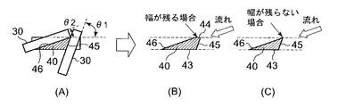
- pillar 40 of the cross-sectional shape different from 1st Embodiment is demonstrated.
- the angular relationship between the plane of the upstream side inclination angle ⁇ 1 and the plane of the downstream side inclination angle ⁇ 2 of the first embodiment is reversed. That is, the inclined plane is set to about 70 ° as the upstream side inclination angle ⁇ 1 and about 20 ° to the downstream side inclination angle ⁇ 2, and each surface is machined using a cutting tool.
- the inscribed arc 43, the circumscribing arc 44, the upstream side surface 45, and the downstream side surface 46 as a whole have a substantially rectangular cross-sectional shape.
- the inscribed arc 43, the upstream side surface 45, and the downstream side surface 46 form a substantially triangular cross-sectional shape as a whole.
- the upstream corner portion of the substantially square or triangular cross-sectional shape is formed at ⁇ 1 and the downstream corner portion at ⁇ 2, and the upstream side surface 45 and the downstream side surface 46 are turned into gas flow. It is formed in the cross-sectional shape inclined so that it may follow.
- the upstream corners and the downstream corners are formed at acute angles of ⁇ 1 and ⁇ 2, and the upstream side 45 and the downstream side are formed. 46 is inclined so as to follow the gas flow, so that both the projected area of the upstream side surface 45 and the projected area of the downstream side surface 46 of the support column 40 are reduced with respect to the gas flow toward the center side while turning the scroll portion 3. This can reduce the loss of gas flow and the occurrence of wake (flow distortion) by the support column 40.
- the projection area with respect to the flow direction is the same as that of the first embodiment, it has the same effects as the gas flow loss reduction and the wake (flow distortion) generation reduction by the support column 21 of the first embodiment.
- FIG. 6 struts 21 are provided at equal intervals of the pitch P in the circumferential direction, and the gas flow is a flow from the swirling flow of the scroll portion 3 toward the center side of the turbine rotor blade 50.
- a speed difference that is, a pressure difference
- This pressure difference causes a pressure fluctuation in the circumferential direction to generate a pressure wave F as indicated by a dotted line, and an excitation force is generated.
- the vibration frequency of the excitation force and the natural frequency of the turbine blade 50 may resonate. In this way, the vibration caused by the circumferential pressure wave generated according to the number of support columns 21 resonates with the natural frequency of the turbine rotor blade 50 is hereinafter referred to as harmonic resonance.
- the vibration of the turbine rotor blade as shown in FIG. 10 was analyzed and expressed in a Campbell diagram for evaluation.
- This diagram represents a straight line indicating the vibration frequency on the vertical axis, the rotational speed of the turbine rotor blade on the horizontal axis, and the harmonic order H.
- the harmonic order H is the ratio between the excitation frequency due to pressure fluctuations generated according to the number of struts and the rotational speed of the turbine rotor blade 50. For example, when the number of struts is 5, the relationship represented by the 5H line The relationship between the rotational speed of the turbine rotor blade 50 and the frequency generated at that time is shown.
- the operating range of the turbine rotor blade 50 is shown up to Nmax, and the lines of the primary natural frequency and the tertiary natural frequency of the turbine rotor blade 50 are set.
- the intersection of the 5H line and the natural frequency (primary mode natural frequency, tertiary mode natural frequency) line of the turbine rotor blade 50 is the resonance point of the resonance mode.
- low-order mode resonance generates a large dynamic stress. Therefore, in order to surely avoid such low-order resonance, it is necessary to shift the resonance point to the low rotation side.
- the natural frequency it is appropriate to select the 6H line or more so as to achieve a resonance state at a rotational speed as low as possible.
- the harmonic order needs to be 10H line or less.
- the stress generated in the turbine blade 50 at resonance is higher than that in the primary mode and the tertiary mode in the analysis of the vibration test result. Since it is small, it is desirable to select the harmonic order to be 12H line or less in order to avoid resonance in the third-order mode.
- the primary natural frequency is 6H line or more in order to achieve a resonance state at as low a rotational speed as possible, and further the 12H line or less where the tertiary natural frequency is out of the operating range.
- the harmonic order H is desirably 6 to 12, and the number of the columns 21 is preferably 6 to 12.
- FIG. 9 shows an arrangement example in the case of eight struts 21. As shown in FIG. 9, the eight struts 21 are arranged at equal intervals to prevent an increase in the resonance stress of the turbine rotor blade 50 due to harmonic resonance.
- the diameter of the inscribed arc 36 of the support column 21 is set to 1.15 or more of the position of the outer diameter of the turbine rotor blade 50, and a diffusion distance of wake (flow strain) generated on the downstream side of the support column 21 is secured.
- the generation of harmonic resonance is further prevented by preventing the pressure wave F caused by the pressure fluctuation in the circumferential direction caused by the support column 21 from entering the turbine rotor blade 50 side.
- the excitation force generated by the pressure fluctuation in the circumferential direction of the inflowing gas by the plurality of support columns 21 arranged in the circumferential direction is the primary mode of the natural vibration of the turbine rotor blade 50. Since resonance is performed on the low rotation side of the operation region, it is possible to prevent the primary mode resonance stress of the turbine rotor blade 50 from becoming excessive and to reduce the stress at the time of resonance. Further, since resonance with the tertiary mode of the natural vibration of the turbine blade 50 is performed outside the operating region, resonance in the tertiary mode of the turbine blade 50 within the operating region can be avoided, and Reliability can be improved.
- the support columns 21 are installed at equal intervals in the third embodiment, but they are installed at unequal intervals. As shown in FIG. 8, only one pitch may be made unequal with the other, and all pitches P1 to P8 may be made unequal.
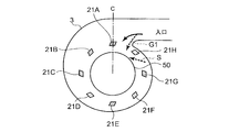
- the fifth embodiment is arranged immediately downstream of the tongue portion 52 constituting the winding end portion of the scroll portion 3.
- the number of the struts 21 is eight, as an example, when the struts 21A to 21H are installed counterclockwise from the position of the center line C of the moving blade turbine 50 as shown in FIG. Since 21H is positioned upstream of the tongue 52 in the turning direction, the gas exiting the tongue 52 flows in like a gas flow G1. Then, since the swirl flow S flowing through the scroll portion 3 and G1 collide with each other, a flow distortion is generated at the gathering portion of the inflow flow and swirl flow S flowing immediately after the tongue 52.
- the gas flowing out of the tongue portion 52 immediately flows to the center side by the support column 21H as in the gas flow G2.
- the flow distortion in the portion is eliminated, and the efficiency reduction of the turbine rotor blade 50 can be suppressed.
- the member on the bearing housing side where the bearing supporting the rotating shaft of the turbine blade is disposed and the member on the outlet side of the exhaust gas passage cross the gas passage on the outer peripheral side of the turbine blade.
- the flow resistance is reduced to improve the inflow characteristics, and resonance of the turbine blades can be avoided to improve the durability and reliability of the turbine blades. Suitable for use.
Landscapes
- Engineering & Computer Science (AREA)
- Mechanical Engineering (AREA)
- General Engineering & Computer Science (AREA)
- Chemical & Material Sciences (AREA)
- Combustion & Propulsion (AREA)
- Chemical Kinetics & Catalysis (AREA)
- General Chemical & Material Sciences (AREA)
- Supercharger (AREA)
- Control Of Turbines (AREA)
- Turbine Rotor Nozzle Sealing (AREA)
Abstract
Description
また、特許文献2、3においては板金製のタービンハウジングのスクロール部を左右2つの両板金部材を突き合わせて周方向に溶接する構造からなっていることが示されているが、スクロール部の中心側を形成するコア部の構造について、特に、タービン動翼の回転軸を支持するベアリングが配設されるベアリングハウジング側の部材と、排ガス流路出口側の部材とを連結して固定する支柱部の構造については示されていない。
さらに、周方向に配置される複数本の支柱によって流入ガスの周方向に圧力変動が生じ、それによって圧力波の励振力が生じ、該励振力がタービン動翼の固有振動と共振するとタービン動翼の信頼性の上で支障をきたす問題がある。このため、特定の励振力が増加することを防ぐように支柱の配置間隔、配置本数、支柱断面形状を設定する必要がある。
そして本第1発明は、各支柱のタービン軸方向視における断面形状がガス流の上流側角部および下流側角部のそれぞれを鋭角に形成して、上流側面および下流側面をガス流に沿うように傾斜されることを特徴とする。
このように支柱の上流側面と下流側面とのそれぞれが平面からなり、全体として略四角形状、または略三角形状からなるため、円環状の連結部材に対して機械加工によって支柱となる部分を残してその間を切削加工によって切除することで容易になり、支柱の製造および加工が、簡単かつ低コストで行うことができる。
一般的に、低次モードの共振は大きな動的応力を生じるため、このような低次の共振を確実に回避するため、共振点を低回転側にずらしてタービン動翼に作用する動的応力を極力低減できる。
ハーモニクス次数Hは、支柱本数に応じて生じる圧力変動による励振動数と、タービン動翼の回転数との比であり、例えば、支柱本数が5本の場合には5H線で回転数と振動数との関係が定まり、5H線とタービン動翼の固有振動数(1次モード)との交点が共振点K1となる。
従って、1次の固有振動数においては、なるべく低い回転数での共振状態となるようにするために、6H線以上となり、さらに、2次モード以上の固有振動数との交点が運転領域を外れるようにするためにはハーモニクス次数は10H線以下とする必要があるが、2次モードについては、加振試験結果の解析より1次モードや3次モードに比べて共振時のタービン動翼50には生じる応力が小さいため、3次モードの共振を回避すべくハーモニクス次数を12H線以下に選択することか望ましい。
従って、1次の固有振動数においては、なるべく低い回転数での共振状態となるようにするために、6H線以上となり、さらに、3次の固有振動数が運転領域を外れるような12H線以下となる。
このように、舌部の直下流に設置することで、舌部から流出した排ガスは直ちに支柱によって中心側への流れが妨げられるため、タービンハウジングのスクロール部を流れてきた流入流れと、舌部直後に流れ込む流入流れとの集合部分における流動ひずみが解消され、すなわち、タービンハウジングに沿った流れを強めることで、舌部近傍における流動ひずみが解消されて、タービン動翼の効率低下を抑制できる。
図1~図4を参照して、本発明の第1実施形態に係るタービンハウジンについて説明する。
図1、2に示すように、板金製のタービンハウジング1は大きく分けてスクロール部3とセンターコア部9と、出口管部23とからなり、さらに、スクロール部3は向かい合わせて設けられる第1スクロール部5と、第2スクロール部7とからなっている。そしてこれら4つの部材が溶接接合されることでタービンハウジング1が形成される。
なお、流路出口部17の先端にはパイプ形状の出口管部23が全周溶接によって接合されている。
なお、溶接は片側すみ肉溶接でなく、板金材の先端同士を突き合わせてその部分を溶接する突合せ溶接によって接合してもよい。また、板金材はオーステナイト系とステンレス鋼等の耐熱鋼によって構成されるとよい。
図3はタービン軸方向視における複数の支柱21が周方向に配置されるとともに、その支柱21の断面形状を示し、支柱21はベアリングハウジング部15と流路出口部17とを有する略円筒形状のセンターコア部9(図2参照)を機械加工、例えば切削加工によって当該支柱21となる部分を残してその間を切除することで加工して、切除した箇所に流路19を形成する。
次に、図7を参照しては、第1実施形態とは異なる断面形状の支柱40について説明する。この第2実施形態は、図5(A)に示すように、第1実施形態の上流側傾斜角度θ1の平面と、下流側傾斜角度θ2の平面との角度関係を逆にしたものである。すなわち、上流側傾斜角度θ1としては約70°、下流側傾斜角度θ2に対しては約20°に設定された傾斜平面とし、それぞれの面は切削工具を用いて加工される。
次に、図6、図7、図10を参照して、第3実施形態について説明する。
第3実施形態は、前記支柱21の本数の設定手法について、支柱21の本数をタービン動翼50の共振振動を回避するように設定することを説明する。
図6に示すように、周方向にピッチPの等間隔で支柱21が設けられ、ガスの流れは、スクロール部3の旋回流れからタービン動翼50の中心側に向かう流れとなる。このとき、支柱21の下流側ではウェーク(流動歪み)が生じるため、支柱21の下流部分と、支柱21間の部分とでは、タービン動翼50の中心側へ入り込む流れに速度差、つまり圧力差が生じる。この圧力差によって周方向に圧力変動が生じて点線で示すような圧力波Fが生じ、励振力が発生する。そして、この励振力がタービン動翼50側に及ぶと、前記励振力の振動数とタービン動翼50の固有振動数とが共振を生じるおそれがある。このように支柱21の本数に応じで生じる周方向圧力波による振動が、タービン動翼50の固有振動数と共振することを以下ハーモニクス共振という。
タービン動翼50の使用運転領域をNmaxまでとして示し、タービン動翼50の1次固有振動数および3次固有振動数のラインがそれぞれ設定されている。そして、5H線とタービン動翼50の固有振動数(1次モード固有振動数、3次モード固有振動数)のラインとの交点が、その共振モードの共振点となる。
従って、1次の固有振動数においては、なるべく低い回転数での共振状態となるようにするために、6H線以上となり、さらに、3次の固有振動数が運転領域を外れるような12H線以下とする。
従って、ハーモニクス次数Hは、6~12が望ましく、支柱21の本数としては6~12本が好適である。例えば、支柱21が8本の場合の配置例を図9に示す。図9のように、8本の支柱21が等間隔に配置されハーモニクス共振によるタービン動翼50の共振応力の増加が防止される。
さらに、タービン動翼50の固有振動の3次モードとは運転領域外で共振するようにするので、運転領域内においてのタービン動翼50の3次モードでの共振を回避でき、タービン動翼の信頼性を向上できる。
次に、図8を参照して、第4実施形態について説明する。
この第4実施形態は、第3実施形態が支柱21を等間隔に設置していたが、それを不等間隔のピッチで設置するものである。図8のようにいずれか1ピッチだけを他のものと不等にしてよく、P1~P8の全てのピッチを不等間隔にしてもよい。
次に、図9を参照して、第5実施形態について説明する。
この第5実施形態は、図9の支柱21のように、スクロール部3の巻き終わり部を構成する舌部52の直下流に配置されるものである。
このように、例えば支柱21の本数が8本の場合を例に説明すると、図7のように等間隔で動翼タービン50の中心線C位置から左回りに支柱21A~21Hまで設置すると、支柱21Hは、舌部52より旋回方向上流側に位置されるため、舌部52を出たガスは、ガス流G1のように流入する。そうすると、スクロール部3を流れてきた旋回流Sと、G1とは衝突するため、舌部52直後に流れ込む流入流れと旋回流Sとの集合部分において流動ひずみを生じる。
Claims (8)
- 渦状の排ガス通路を構成するスクロール部が板金製のスクロール部材を向い合わせて接合して形成される板金タービンハウジングにおいて、
タービン動翼の回転軸を支持するベアリングが配設されるベアリングハウジング側の部材と、タービン動翼の外側を形成する流路出口側の部材とをタービン軸方向に連結する支柱をタービン動翼の外周側に周方向に複数本間隔を存して設けたことを特徴とする板金タービンハウジング。 - 前記各支柱のタービン軸方向視における断面形状がガス流の上流側角部および下流側角部のそれぞれを鋭角に形成して、上流側面および下流側面をガス流に沿うように傾斜されることを特徴とする請求項1記載の板金タービンハウジング。
- 前記支柱の断面形状の上流側角部および下流側角部のそれぞれの角度は20°~70°であることを特徴とする請求項1若しくは2記載の板金タービンハウジング。
- 前記支柱の断面形状は、内接円弧と外接円弧と上流側面と下流側面とを有した略四角形状、または前記内接円弧または外接円弧のいずれかの幅が存在しない略三角形状からなることを特徴とする請求項1若しくは2記載の板金タービンハウジング。
- 前記複数本の支柱による流入ガスの周方向の圧力変動によって生じる励振力が、前記タービン動翼の固有振動の1次モードと運転領域の低回転側で共振し、かつ前記タービン動翼の固有振動の2次モード以上と運転領域外の回転数で共振するように支柱の本数が設定されることを特徴とする請求項1若しくは2記載の板金タービンハウジング。
- 前記支柱は6~12本設置されたことを特徴とする請求項1又は2若しくは5記載の板金タービンハウジング。
- 前記支柱を不等ピッチで周方向に設置したことを特徴とする請求項1又は2若しくは5記載の板金タービンハウジング。
- 前記支柱のいずれか1つが、スクロール部の巻き終わり部を構成する舌部の直下流に配置されたことを特徴とする請求項1乃至7のいずれか1項に記載の板金タービンハウジング。
Priority Applications (5)
| Application Number | Priority Date | Filing Date | Title |
|---|---|---|---|
| CN201080029321.4A CN102472115B (zh) | 2009-12-21 | 2010-12-15 | 涡轮壳体 |
| EP10839268.9A EP2441924B1 (en) | 2009-12-21 | 2010-12-15 | Turbine housing |
| EP17177617.2A EP3260670B1 (en) | 2009-12-21 | 2010-12-15 | Turbine housing |
| KR1020117031317A KR101329507B1 (ko) | 2009-12-21 | 2010-12-15 | 터빈 하우징 |
| US13/384,913 US9194292B2 (en) | 2009-12-21 | 2010-12-15 | Turbine housing |
Applications Claiming Priority (2)
| Application Number | Priority Date | Filing Date | Title |
|---|---|---|---|
| JP2009-289414 | 2009-12-21 | ||
| JP2009289414A JP5357738B2 (ja) | 2009-12-21 | 2009-12-21 | タービンハウジング |
Publications (1)
| Publication Number | Publication Date |
|---|---|
| WO2011078035A1 true WO2011078035A1 (ja) | 2011-06-30 |
Family
ID=44195565
Family Applications (1)
| Application Number | Title | Priority Date | Filing Date |
|---|---|---|---|
| PCT/JP2010/072584 Ceased WO2011078035A1 (ja) | 2009-12-21 | 2010-12-15 | タービンハウジング |
Country Status (6)
| Country | Link |
|---|---|
| US (1) | US9194292B2 (ja) |
| EP (2) | EP2441924B1 (ja) |
| JP (1) | JP5357738B2 (ja) |
| KR (1) | KR101329507B1 (ja) |
| CN (1) | CN102472115B (ja) |
| WO (1) | WO2011078035A1 (ja) |
Cited By (2)
| Publication number | Priority date | Publication date | Assignee | Title |
|---|---|---|---|---|
| US20130156567A1 (en) * | 2010-02-01 | 2013-06-20 | Mitsubishi Heavy Industries, Ltd. | Sheet metal turbine housing |
| JP2015140689A (ja) * | 2014-01-27 | 2015-08-03 | 株式会社三五 | タービンハウジング |
Families Citing this family (19)
| Publication number | Priority date | Publication date | Assignee | Title |
|---|---|---|---|---|
| DE102012209562B4 (de) | 2012-06-06 | 2017-08-31 | Continental Automotive Gmbh | Turbinengehäuse für einen Abgasturbolader |
| DE102012209560A1 (de) * | 2012-06-06 | 2013-12-12 | Continental Automotive Gmbh | Turbinengehäuse für einen Abgasturbolader |
| CN105940203B (zh) * | 2014-02-28 | 2019-08-06 | 三菱重工发动机和增压器株式会社 | 金属板涡轮壳体 |
| US10443414B2 (en) * | 2014-07-03 | 2019-10-15 | Mitsubishi Heavy Industries Engine & Turbocharger, Ltd. | Turbine casing, turbine, core for casting turbine casing, and method for producing turbine casing |
| JP6204398B2 (ja) * | 2015-03-23 | 2017-09-27 | カルソニックカンセイ株式会社 | タービンハウジング |
| US10519806B2 (en) * | 2015-11-06 | 2019-12-31 | Calsonic Kansei Corporation | Turbine housing |
| CN109312659B (zh) * | 2016-12-21 | 2021-07-16 | 三菱重工发动机和增压器株式会社 | 涡轮增压器、涡轮增压器的喷嘴叶片以及涡轮机 |
| US10436069B2 (en) | 2017-01-30 | 2019-10-08 | Garrett Transportation I Inc. | Sheet metal turbine housing with biaxial volute configuration |
| US10494955B2 (en) | 2017-01-30 | 2019-12-03 | Garrett Transportation I Inc. | Sheet metal turbine housing with containment dampers |
| US10472988B2 (en) | 2017-01-30 | 2019-11-12 | Garrett Transportation I Inc. | Sheet metal turbine housing and related turbocharger systems |
| US10544703B2 (en) | 2017-01-30 | 2020-01-28 | Garrett Transportation I Inc. | Sheet metal turbine housing with cast core |
| US10690144B2 (en) | 2017-06-27 | 2020-06-23 | Garrett Transportation I Inc. | Compressor housings and fabrication methods |
| DE102018105827A1 (de) * | 2018-03-14 | 2019-09-19 | Man Energy Solutions Se | Verschalung eines Turboladers und Turbolader |
| DE102018221161B4 (de) * | 2018-12-06 | 2021-08-26 | Vitesco Technologies GmbH | Abgasturbine eines Abgasturboladers sowie Abgasturbolader mit einem strömungstechnischen Störelement im Turbinengehäuse |
| US11732729B2 (en) | 2021-01-26 | 2023-08-22 | Garrett Transportation I Inc | Sheet metal turbine housing |
| US12179425B2 (en) | 2023-02-01 | 2024-12-31 | Hamilton Sundstrand Corporation | Metal plated additively manufactured plastic rotor shrouds and their method of manufacturing |
| US12571421B2 (en) | 2023-02-01 | 2026-03-10 | Hamilton Sundstrand Corporation | Metal plated additively manufactured plastic shafts and their method of manufacturing |
| US20240254896A1 (en) * | 2023-02-01 | 2024-08-01 | Hamilton Sundstrand Corporation | Metal plated additively manufactured plastic housing |
| US12421859B2 (en) | 2023-02-01 | 2025-09-23 | Hamilton Sundstrand Corporation | Metal plated additively manufactured plastic seal plates and their method of manufacturing |
Citations (5)
| Publication number | Priority date | Publication date | Assignee | Title |
|---|---|---|---|---|
| JP2003314290A (ja) * | 2002-04-23 | 2003-11-06 | Aisin Seiki Co Ltd | 可変容量ターボチャージャ |
| JP2003536009A (ja) * | 2000-06-07 | 2003-12-02 | ボーグワーナー・インコーポレーテッド | 排気ターボ過給機のタービン用のケーシング組立体 |
| JP2006527322A (ja) * | 2003-06-06 | 2006-11-30 | アイ・エイチ・アイ チャージング システムズ インターナショナル ゲーエムベーハー | 排ガスターボチャージャ用排ガスタービン |
| JP2008106667A (ja) * | 2006-10-25 | 2008-05-08 | Aisin Takaoka Ltd | タービンハウジング |
| JP2009209701A (ja) * | 2008-02-29 | 2009-09-17 | Mitsubishi Heavy Ind Ltd | タービンおよびこれを備えるターボチャージャ |
Family Cites Families (10)
| Publication number | Priority date | Publication date | Assignee | Title |
|---|---|---|---|---|
| IN152940B (ja) * | 1978-10-20 | 1984-05-05 | Cummins Engine Co Inc | |
| US7074009B2 (en) | 2000-06-07 | 2006-07-11 | Borgwarner, Inc. | Casing assembly for the turbine of an exhaust turbochanger |
| DE10218436C1 (de) | 2002-04-25 | 2003-08-14 | Benteler Automobiltechnik Gmbh | Abgasturbine für einen Turbolader |
| CN1231664C (zh) * | 2003-06-11 | 2005-12-14 | 高德瑜 | 水力涡轮机系统 |
| US7280950B2 (en) * | 2004-01-22 | 2007-10-09 | Electro-Motive Diesel, Inc. | Locomotive diesel engine turbocharger and turbine stage constructed with turbine blade vibration suppression methodology |
| DE102004039477B4 (de) | 2004-08-14 | 2015-01-08 | Ihi Charging Systems International Gmbh | Turbinengehäuse für einen Abgasturbolader |
| GB0610248D0 (en) | 2006-05-24 | 2006-07-05 | Integral Powertrain | Twin entry variable geometry turbine housing |
| JP4835330B2 (ja) | 2006-08-31 | 2011-12-14 | トヨタ自動車株式会社 | タービンハウジング |
| JP4643525B2 (ja) | 2006-08-31 | 2011-03-02 | トヨタ自動車株式会社 | エンジンシステム |
| CN101965460B (zh) | 2007-11-20 | 2014-08-13 | 曼·胡默尔有限公司 | 用于离心压缩机的壳体 |
-
2009
- 2009-12-21 JP JP2009289414A patent/JP5357738B2/ja not_active Expired - Fee Related
-
2010
- 2010-12-15 WO PCT/JP2010/072584 patent/WO2011078035A1/ja not_active Ceased
- 2010-12-15 US US13/384,913 patent/US9194292B2/en not_active Expired - Fee Related
- 2010-12-15 CN CN201080029321.4A patent/CN102472115B/zh not_active Expired - Fee Related
- 2010-12-15 KR KR1020117031317A patent/KR101329507B1/ko not_active Expired - Fee Related
- 2010-12-15 EP EP10839268.9A patent/EP2441924B1/en not_active Not-in-force
- 2010-12-15 EP EP17177617.2A patent/EP3260670B1/en active Active
Patent Citations (5)
| Publication number | Priority date | Publication date | Assignee | Title |
|---|---|---|---|---|
| JP2003536009A (ja) * | 2000-06-07 | 2003-12-02 | ボーグワーナー・インコーポレーテッド | 排気ターボ過給機のタービン用のケーシング組立体 |
| JP2003314290A (ja) * | 2002-04-23 | 2003-11-06 | Aisin Seiki Co Ltd | 可変容量ターボチャージャ |
| JP2006527322A (ja) * | 2003-06-06 | 2006-11-30 | アイ・エイチ・アイ チャージング システムズ インターナショナル ゲーエムベーハー | 排ガスターボチャージャ用排ガスタービン |
| JP2008106667A (ja) * | 2006-10-25 | 2008-05-08 | Aisin Takaoka Ltd | タービンハウジング |
| JP2009209701A (ja) * | 2008-02-29 | 2009-09-17 | Mitsubishi Heavy Ind Ltd | タービンおよびこれを備えるターボチャージャ |
Non-Patent Citations (1)
| Title |
|---|
| See also references of EP2441924A4 * |
Cited By (3)
| Publication number | Priority date | Publication date | Assignee | Title |
|---|---|---|---|---|
| US20130156567A1 (en) * | 2010-02-01 | 2013-06-20 | Mitsubishi Heavy Industries, Ltd. | Sheet metal turbine housing |
| US9581045B2 (en) * | 2010-02-01 | 2017-02-28 | Mitsubishi Heavy Industries, Ltd. | Sheet metal turbine housing |
| JP2015140689A (ja) * | 2014-01-27 | 2015-08-03 | 株式会社三五 | タービンハウジング |
Also Published As
| Publication number | Publication date |
|---|---|
| KR20120015458A (ko) | 2012-02-21 |
| EP2441924A4 (en) | 2014-07-09 |
| EP2441924A1 (en) | 2012-04-18 |
| EP2441924B1 (en) | 2018-01-24 |
| JP5357738B2 (ja) | 2013-12-04 |
| CN102472115A (zh) | 2012-05-23 |
| US9194292B2 (en) | 2015-11-24 |
| KR101329507B1 (ko) | 2013-11-13 |
| CN102472115B (zh) | 2015-06-03 |
| US20120275914A1 (en) | 2012-11-01 |
| JP2011127575A (ja) | 2011-06-30 |
| EP3260670B1 (en) | 2020-01-15 |
| EP3260670A1 (en) | 2017-12-27 |
Similar Documents
| Publication | Publication Date | Title |
|---|---|---|
| JP5357738B2 (ja) | タービンハウジング | |
| JP5769407B2 (ja) | 板金タービンハウジング | |
| US8740557B2 (en) | Fabricated static vane ring | |
| US8206094B2 (en) | Stationary blade ring of axial compressor | |
| JP5047364B2 (ja) | ラジアルタービンのスクロール構造 | |
| US7614150B2 (en) | Method for manufacturing a stator or rotor component | |
| EP2187062B1 (en) | Assembling method of a stator blade ring segment, and stator blade ring segment | |
| JP6072299B2 (ja) | 板金タービンハウジング | |
| US8684670B2 (en) | Sealing mechanism with bellows and steam turbine provided with the sealing mechanism | |
| RU2331778C2 (ru) | Способ изготовления компонента статора или ротора | |
| KR101531779B1 (ko) | 터빈 정익 및 가스 터빈 | |
| WO2019097947A1 (ja) | ガスタービンの燃焼筒及び燃焼器並びにガスタービン | |
| JPWO2017203917A1 (ja) | 回転体、および、過給機 | |
| JP2011179370A (ja) | ターボチャージャおよびそのホイールハウジング | |
| CN115335588B (zh) | 用于涡轮机的支柱罩 | |
| JP6756008B2 (ja) | ターボチャージャ | |
| US7775050B2 (en) | Method and apparatus for reducing stresses induced to combustor assemblies | |
| JP5014703B2 (ja) | エキゾーストマニホールド | |
| JP2015224570A (ja) | ターボチャージャ | |
| JP2024068475A (ja) | 排気管 |
Legal Events
| Date | Code | Title | Description |
|---|---|---|---|
| WWE | Wipo information: entry into national phase |
Ref document number: 201080029321.4 Country of ref document: CN |
|
| 121 | Ep: the epo has been informed by wipo that ep was designated in this application |
Ref document number: 10839268 Country of ref document: EP Kind code of ref document: A1 |
|
| ENP | Entry into the national phase |
Ref document number: 20117031317 Country of ref document: KR Kind code of ref document: A |
|
| WWE | Wipo information: entry into national phase |
Ref document number: 2010839268 Country of ref document: EP |
|
| WWE | Wipo information: entry into national phase |
Ref document number: 13384913 Country of ref document: US |
|
| NENP | Non-entry into the national phase |
Ref country code: DE |