WO2011078042A1 - コネクター - Google Patents
コネクター Download PDFInfo
- Publication number
- WO2011078042A1 WO2011078042A1 PCT/JP2010/072612 JP2010072612W WO2011078042A1 WO 2011078042 A1 WO2011078042 A1 WO 2011078042A1 JP 2010072612 W JP2010072612 W JP 2010072612W WO 2011078042 A1 WO2011078042 A1 WO 2011078042A1
- Authority
- WO
- WIPO (PCT)
- Prior art keywords
- housing
- contact
- sensor element
- connector
- fitting
- Prior art date
- Legal status (The legal status is an assumption and is not a legal conclusion. Google has not performed a legal analysis and makes no representation as to the accuracy of the status listed.)
- Ceased
Links
Images


Classifications
-
- H—ELECTRICITY
- H01—ELECTRIC ELEMENTS
- H01R—ELECTRICALLY-CONDUCTIVE CONNECTIONS; STRUCTURAL ASSOCIATIONS OF A PLURALITY OF MUTUALLY-INSULATED ELECTRICAL CONNECTING ELEMENTS; COUPLING DEVICES; CURRENT COLLECTORS
- H01R12/00—Structural associations of a plurality of mutually-insulated electrical connecting elements, specially adapted for printed circuits, e.g. printed circuit boards [PCB], flat or ribbon cables, or like generally planar structures, e.g. terminal strips, terminal blocks; Coupling devices specially adapted for printed circuits, flat or ribbon cables, or like generally planar structures; Terminals specially adapted for contact with, or insertion into, printed circuits, flat or ribbon cables, or like generally planar structures
- H01R12/50—Fixed connections
- H01R12/59—Fixed connections for flexible printed circuits, flat or ribbon cables or like structures
- H01R12/592—Fixed connections for flexible printed circuits, flat or ribbon cables or like structures connections to contact elements
-
- G—PHYSICS
- G01—MEASURING; TESTING
- G01N—INVESTIGATING OR ANALYSING MATERIALS BY DETERMINING THEIR CHEMICAL OR PHYSICAL PROPERTIES
- G01N27/00—Investigating or analysing materials by the use of electric, electrochemical, or magnetic means
- G01N27/26—Investigating or analysing materials by the use of electric, electrochemical, or magnetic means by investigating electrochemical variables; by using electrolysis or electrophoresis
- G01N27/403—Cells and electrode assemblies
- G01N27/406—Cells and probes with solid electrolytes
- G01N27/407—Cells and probes with solid electrolytes for investigating or analysing gases
-
- H—ELECTRICITY
- H01—ELECTRIC ELEMENTS
- H01R—ELECTRICALLY-CONDUCTIVE CONNECTIONS; STRUCTURAL ASSOCIATIONS OF A PLURALITY OF MUTUALLY-INSULATED ELECTRICAL CONNECTING ELEMENTS; COUPLING DEVICES; CURRENT COLLECTORS
- H01R13/00—Details of coupling devices of the kinds covered by groups H01R12/70 or H01R24/00 - H01R33/00
- H01R13/40—Securing contact members in or to a base or case; Insulating of contact members
- H01R13/42—Securing in a demountable manner
- H01R13/428—Securing in a demountable manner by resilient locking means on the contact members; by locking means on resilient contact members
- H01R13/432—Securing in a demountable manner by resilient locking means on the contact members; by locking means on resilient contact members by stamped-out resilient tongue snapping behind shoulder in base or case
Definitions
- the present invention relates to a connector.
- Patent Document 1 describes a gas sensor including a flat sensor element that detects gas, a conductor such as a lead wire, and a connector that connects the sensor element and the conductor.
- the connector of the gas sensor includes a contact fitting electrically connected to the sensor element and a housing for holding the same, and the sensor element is sandwiched between the two housings.
- Such conventional contact fittings 201a to 201c and the housing 200 are shown in FIG.
- the contact fittings 201a to 201c are provided with protrusions 202a to 202c, which are brought into contact with and electrically connected to the front surface electrode portion or the back surface electrode portion of the sensor element.
- the contact fittings 201a to 201c include hook portions 203a to 203c that are curved in a direction perpendicular to the longitudinal direction of the contact fittings 201a to 201c and toward the outside of the contact fittings 201a to 201c.
- the contact fittings 201a to 201c are arranged in a direction perpendicular to the longitudinal direction of the contact fittings 201a to 201c, and are locked to the housing 200 by the hook portions 203a to 203c.
- the present invention has been made to solve such a problem, and has as its main object to provide a connector that can be further miniaturized.
- the connector of the present invention employs the following means in order to achieve the main object described above.
- the connector of the present invention A connector electrically connected to a plurality of front surface electrode portions arranged in parallel on the surface of the flat sensor element and a plurality of back surface electrode portions arranged in parallel on the back surface, A first housing that holds a plurality of elongated contact fittings arranged in a direction substantially orthogonal to the longitudinal direction of the contact fittings at positions facing the plurality of surface electrode portions of the sensor element; A second housing for holding a plurality of elongated contact fittings arranged in a direction substantially orthogonal to the longitudinal direction of the contact fittings at positions facing the plurality of back surface electrode portions of the sensor element;
- the contact metal fitting is formed by bending a die-cutting material having a substantially rectangular metal plate portion and a metal piece connected to one long side of the metal plate portion, and the metal plate portion has the surface electrode Or a conductive portion that can come into contact with the back electrode portion, and the metal piece fits in a region directly above the surface of the metal plate portion opposite to the surface electrode portion or the side in contact with the
- the first housing holds a plurality of elongate contact fittings arranged in a direction substantially perpendicular to the longitudinal direction of the contact fitting at a position facing the plurality of surface electrode portions on the surface of the flat sensor element.
- the second housing holds a plurality of elongated contact fittings arranged in a direction substantially orthogonal to the longitudinal direction of the contact fittings at positions facing the plurality of back surface electrode portions on the back surface of the flat sensor element.
- the contact fitting is formed by bending a die-cutting material having a substantially rectangular metal plate portion and a metal piece connected to one long side of the metal plate portion, and the metal piece is a surface of the metal plate portion.
- a plurality of contact fittings are arranged in a direction substantially orthogonal to the longitudinal direction of the contact fitting, as compared with the hook portion being curved in a direction perpendicular to the longitudinal direction of the metal plate portion and toward the outside of the contact fitting.
- the arrangement width of the contact fittings when held in a state can be reduced, and the first housing and the second housing can be downsized. That is, the connector can be miniaturized.
- a regulating member that regulates a distance between the first housing and the second housing, each surface electrode portion of the sensor element, and a conduction portion of each contact fitting of the first housing.
- each back electrode part of the sensor element and a conducting part of each contact metal fitting of the second housing face each other, and press the first housing and the second housing in a direction approaching each other.
- the distance between the first housing and the second housing is fixed by the restricting member, and the conducting portion of the contact fitting of the first housing and the conducting portion of the contact fitting of the second housing are elastically deformed.
- a housing fixing member that clamps and fixes the sensor element with a pressing force generated by the pressing.
- the conducting part clamps the sensor element with the pressing force due to elastic deformation, and therefore the conducting part is less likely to be separated from the sensor element.
- the electrical contact between the conductive portion, the front surface electrode portion, and the back surface electrode portion can be more reliably maintained, and the sensor element can be more securely sandwiched.
- the distance between the first housing and the second housing is fixed by the regulating member, even if excessive pressure is applied from the outside, the pressure does not reach the conducting portion, and the conducting portion is plastically deformed by the pressure. Can be prevented. As a result, the electrical contact and the clamping of the sensor element can be maintained for a long period of time, and the life of the connector becomes longer.
- the contact fitting has a spring constant of 500 to 4000 N / mm of the conducting portion.
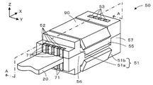
- FIG. 4 is a perspective view of a connector 50.
- FIG. 3 is an exploded perspective view showing a housing 51 of a connector 50.
- FIG. FIG. 3 is a cross-sectional view taken along line AA in FIG. 2.
- FIG. 5 is a sectional view taken along line BB in FIG. 4.
- It is explanatory drawing which shows the positional relationship of the contact metal fitting 71 and the sensor element 20 seen from the 1st housing 51a side. It is a graph which shows the relationship between the displacement of the support part 71b and the conduction
- FIG. It is explanatory drawing which shows the contact metal fitting 71 after a bending process.
- FIG. 6 is an explanatory view of contact fittings 201a to 201c and a housing 200 of a conventional example.
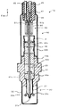
- FIG. 1 is a longitudinal sectional view of a gas sensor 10 according to an embodiment of the present invention
- FIG. 2 is a perspective view of a connector 50
- FIG. 3 is an exploded perspective view showing a housing 51 of the connector 50
- 4 is a cross-sectional view taken along line AA in FIG. 2
- FIG. 5 is a cross-sectional view taken along line BB in FIG. 4
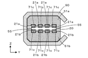
- FIG. 6 shows the positions of the contact fitting 71 and the sensor element 20 as viewed from the first housing 51a side. It is explanatory drawing which shows a relationship.
- the gas sensor 10 is electrically connected to a sensor element 20 that measures a predetermined gas component from a gas to be measured, a protective cover 30 that protects one end of the sensor element 20, and the sensor element 20. And a sensor assembly 40 including a connector 50.
- This gas sensor 10 is attached to an exhaust gas pipe of a vehicle, for example, and is used for measuring gas components such as NOx and O 2 contained in exhaust gas as a gas to be measured.
- the sensor element 20 is an element having an elongated plate-like body shape, and is formed by stacking, for example, six ceramic substrates made of an oxygen ion conductive solid electrolyte layer such as zirconia (ZrO 2 ).
- the end of the sensor element 20 on the protective cover 30 side is referred to as the front end, and the end on the connector 50 side is referred to as the base end.
- four front surface electrodes 21a and four back surface electrodes 21b are formed on the base end surface and the back surface of the sensor element 20.
- the front electrode 21a and the back electrode 21b are collectively referred to as the electrode 21.
- the electrode 21 is used to apply a voltage to the sensor element 20 and to extract an electromotive force or current generated according to the concentration of the gas component detected by the sensor element 20. It is electrically connected to the electrode in the tip of the sensor element 20 (not shown). The positions of the front electrode 21a and the back electrode 21b will be described later.
- the protective cover 30 is disposed so as to surround the periphery of the tip of the sensor element 20.
- the protective cover 30 includes an inner protective cover 31 that covers the tip of the sensor element 20 and an outer protective cover 32 that covers the inner protective cover 31.
- the inner protective cover 31 is formed in a cylindrical shape and includes an inner protective cover hole 31 a for introducing a gas to be measured at the tip of the sensor element 20.
- the outer protective cover 32 is formed in a bottomed cylindrical shape, and includes an outer protective cover hole 32a for introducing a gas to be measured on the side surface.
- the inner protective cover 31 and the outer protective cover 32 are made of metal such as stainless steel, for example.
- the sensor assembly 40 includes a metal metal shell 41, a cylindrical inner cylinder 42 and an outer cylinder 46 that are welded and fixed to the metal shell 41, and a connector 50 that is connected to the base end of the sensor element 20. ing.
- the metal shell 41 can be attached to, for example, an exhaust pipe of a vehicle by a male screw portion 41a.
- Inside the inner cylinder 42 a plurality of ceramic supporters 43a to 43c and ceramic powders 44a, 44b such as talc filled between the ceramic supporters 43a, 43b and between the ceramic supporters 43b, 43c are enclosed.
- the outer cylinder 46 covers the periphery of the inner cylinder 42, the sensor element 20, and the connector 50, and a lead wire 45 connected to the connector 50 is drawn out to the outside.
- the lead wire 45 is electrically connected to each electrode 21 of the sensor element 20 via the connector 50.
- a gap between the outer tube 46 and the lead wire 45 is sealed with a rubber plug 47.
- the sensor element 20 passes through the ceramic supporters 43a to 43c and the ceramic powders 44a and 44b, and is mainly fixed by the metal shell 41 and the ceramic powders 44a and 44b. Therefore, for example, when the gas sensor 10 is attached to a vibrating environment such as a vehicle, the sensor element 20, the connector 50, and the lead wire 45 on the connector 50 side of the upper end P with the upper end P of the ceramic supporter 43 c as a fulcrum. Vibrates. On the other hand, since the sensor element 20 closer to the protective cover 30 than the upper end P is covered with the metal shell 41 and the ceramic powders 44a and 44b, the influence of vibration is relatively small.
- the connector 50 has a first housing 51a and a second housing 51b made of ceramics such as an alumina sintered body, and is held by the first housing 51a or the second housing 51b, one-to-one with the electrode 21 of the sensor element 20. And a metal clamp 90 that sandwiches and fixes the first housing 51a and the second housing 51b.
- the first housing 51 a and the second housing 51 b are members that hold the four contact fittings 71 side by side in a direction (Y direction) orthogonal to the longitudinal direction (X direction) of the contact fitting 71. Since the first housing 51a and the second housing 51b have the same shape, the same components in the first housing 51a and the second housing 51b will be described with the same reference numerals.
- the first housing 51a and the second housing 51b are collectively referred to as a housing 51.
- the housing 51 includes four locking grooves 52 for locking the contact fitting 71, four insertion holes 53 into which the contact fitting 71 is inserted, and a latch formed in each insertion hole 53 for locking the contact fitting 71. A stop 54.
- the housing 51 includes a protrusion 55 on one side surface in the Y direction across the sensor element 20, and a regulating member 56 that regulates the distance in the Z direction between the first housing 51a and the second housing 51b on the other side surface. , 57 (see FIGS. 2 and 3).
- the projecting portion 55 is inserted into a recess between the regulating member 56 and the regulating member 57 of the opposing housing 51, whereby the relative position in the X direction between the first housing 51a and the second housing 51b. Can be fixed.
- the contact fitting 71 is held by the housing 51 at a position facing the electrode 21 of the sensor element 20 on a one-to-one basis, and has a distal end portion 71a locked to the locking groove 52 by a curved shape, and the sensor element 20.
- the support part 71b curved toward the sensor element 20, the conduction part 71c contacting the electrode 21 by being curved toward the sensor element 20, the upright part 71d inserted into the insertion hole 53, and the connector 50.
- a connecting portion 71f electrically connected to the lead wire 45.
- the conductive portion 71c of the contact fitting 71 held by the first housing 51a is in one-to-one contact with the surface electrode 21a of the sensor element 20, and the conduction of the contact fitting 71 held by the second housing 51b.
- the part 71c is in contact with the back electrode 21b of the sensor element 20 in a one-to-one relationship (see FIGS. 4 and 5).
- the upright portion 71d includes a hook portion 71e that is locked to the locking portion 54 with a curved shape.
- the surface electrode 21a of the sensor element 20 is formed from the base end of the sensor element 20 to a position between the conduction portion 71c and the support portion 71b.
- the center two surface electrodes 21a are electrically connected to the through hole 21e formed to be electrically connected to the electric path inside the sensor element 20 described above.
- each through hole 21e is formed at a position between the conduction portion 71c and the support portion 71b. Note that the positional relationship between the back electrode 21b and the contact fitting 71 and the position of the through hole 21e that conducts to the back electrode 21b are the same as this, and thus the description thereof is omitted.
- the clamp 90 is formed by bending a plate-shaped metal, and has an elastic force that can be pressed in a direction in which the first housing 51a and the second housing 51b are sandwiched.
- the regulating members 56 and 57 of the first housing 51a come into contact with the second housing 51b and the regulating members 56 and 57 of the second housing 51b Contact the first housing 51a. Thereby, the distance between the first housing 51a and the second housing 51b is fixed.
- the clamp 90 is in a state in which the sensor element 20 is sandwiched between the first housing 51a and the second housing 51b so that the conducting portion 71c of the contact fitting 71 faces the front electrode 21a or the back electrode 21b of the sensor element 20.
- the support portion 71b and the conducting portion 71c are elastically deformed by the pressing force of the clamp 90, and the sensor element 20 is clamped and fixed.
- the support part 71b and the conduction part 71c are elastically deformed, the sensor element 20 can be securely clamped and fixed by the pressing force thereby.
- electrical_connection part 71c is elastically deformed, the electrical contact with the conduction
- the distance between the first housing 51a and the second housing 51b is fixed by the regulating members 56 and 57, even if excessive external pressure is applied, the pressure reaches the support portion 71b and the conduction portion 71c. These plastic deformations due to shear pressure can be prevented. Therefore, electrical contact between the connector 50 and the sensor element 20 and clamping of the sensor element 20 can be maintained for a long period of time.
- the support portion 71b and the conduction portion 71c are a pressing force from the clamp 90 in a state where the distance between the first housing 51a and the second housing 51b is fixed to the regulating members 56 and 57, and a pressing force with a predetermined margin. In this range, the material and the method of bending are determined in consideration of the plastic deformation.
- the spring constants of the support portion 71b and the conduction portion 71c are more preferably in the range of 500 to 4000 N / mm. This spring constant is a spring constant in a direction (Z direction) perpendicular to the tangent to the top of the support portion 71b and the conduction portion 71c in the state where it is assembled to each housing 51.
- the straight line A is along the downward arrow.
- the straight line A increases along the upward arrow.
- the material and the way of bending may be appropriately set.
- the load decreases to 50 N and the displacement reaches 100 ⁇ m, and then the straight line B (spring constant 1000 N / mm) is applied when the load decreases in the range of 0 to 50 N.
- a material or the like may be set so that the line B decreases along the upward arrow when the load decreases along the downward arrow and the load increases.
- the load becomes 100 N and the displacement becomes 200 ⁇ m.
- the straight line C spring constant 4000 N / mm
- the material or the like may be set so that the straight line C increases along the upward arrow.
- the spring constants of the support portion 71b and the conductive portion 71c after the assembly of the sensor element 20 and the connector 50 is completed can be set to 500 to 4000 N / mm.
- the protrusions 202a to 202c are in contact with the electrodes.
- the support part 71b and the conduction part 71c which are shapes in which the protrusions 202a to 202c are formed by bending a metal as in this embodiment, they cannot have an elastic force. Therefore, when the sensor element is sandwiched between the two housings 200, if there is a member that fixes the distance between the housings, such as the regulating members 56 and 57 of the present embodiment, the protrusions 202a to 202c may be separated from the electrodes depending on the accuracy of the member. It may float and be counterproductive.
- the protruding portion is not elastically deformed, so that the protruding portion may float from the electrode depending on the accuracy of the member. In the example of FIG. 10, this is unlikely to occur because there are three projections and there is always a plane that contacts all three points, but such a problem is likely to occur when four or more projections are required. .
- the contact fitting 71 is manufactured by punching a plate-like metal and bending it.
- the plate-like metal is die-cut into a shape having a substantially rectangular metal plate portion 100 and a metal piece 110 connected to one long side of the metal plate portion 100.
- the regions 100a and 100f of the metal plate portion 100 are curved toward the front side of the sheet of FIG. 8 to form the tip portion 71a and the connection portion 71f shown in FIG. 4, and the regions 100b and 100c are formed at the back of the page of FIG.
- electrical_connection part 71c shown in FIG. 4 are formed by curving to the side.
- the metal piece 110 bends the region 111 90 ° toward the front side of the drawing with the straight line 111a as a fulcrum, bends the region 112 with the straight line 112a as a fulcrum toward the inside of the metal plate portion 100, and the region 113 A hook portion 71e is formed by bending in the direction of the connecting portion 71f along the longitudinal direction. Thereby, the metal piece 110 is bent into the upright portion 71d.
- the contact fitting 71 after bending is shown in FIG. By manufacturing the contact fitting 71 in this manner, the contact fitting 71 having a three-dimensional shape can be easily manufactured from a plate-like metal. Further, as shown in FIGS.
- the metal plate portion 100 is formed with a recess 101 having a depth greater than or equal to the thickness of the region 111.
- the region 111 is bent with the straight line 111a as a fulcrum, the region 111 falls within a region immediately above the surface 102 of the metal plate portion 100.
- the widths of the regions 112 and 113 are determined so as to be within the region immediately above the surface 102 of the metal plate portion 100, and the hook portion 71 e connects the region 113 along the longitudinal direction of the metal plate portion 100. Since it is curved in the direction of the portion 71 f, the entire upright portion 71 d is also within the region directly above the surface 102 of the metal plate portion 100.
- the arrangement width when holding the contact fittings 71 in a state perpendicular to the longitudinal direction of the contact fittings 71 can be reduced, and as a result
- the housing 51 can be downsized. That is, the connector 50 can be downsized.
- the connector 50 and the sensor element 20 are connected by the contact fitting 71 that is an elastic body, the vibration propagated to the outer tube 46 ⁇ the rubber plug 47 ⁇ the lead wire 45 ⁇ the connector 50 is not directly applied to the sensor element 20. Do not propagate. In the conventional example as shown in FIG.
- the hook portions 203a to 203c are curved in a direction perpendicular to the longitudinal direction of the contact fittings 201a to 201c and toward the outside of the contact fittings 201a to 201c. Therefore, it is necessary to increase the arrangement width of the contact fittings 201a to 201c by the amount of the hook portions 203a to 203c, and the housing 200 becomes large. Further, in FIG. 10, in order to make the housing 200 as small as possible, the arrangement width of the contact fittings 201a to 201c is increased only around the hook portions 203a to 203c, and the arrangement width of the contact fittings 201a to 201c around the protrusions 202a to 202c. Is made smaller.
- the contact metal fittings 201a, 201b, 201c become different shapes, it becomes necessary to manufacture the contact metal fittings 201a, 201b, 201c in separate steps.
- the plurality of contact fittings 71 can have the same shape, and the connector 50 can be made smaller than the conventional example.
- the contact fitting 71 is obtained by bending a die cutting material having a substantially rectangular metal plate portion 100 and a metal piece 110 connected to one long side of the metal plate portion 100.
- the metal piece 110 is bent along the longitudinal direction of the metal plate portion 100 by being bent so as to be within the region immediately above the surface of the metal plate portion 100 opposite to the side in contact with the surface electrode 21a or the back electrode 21b.
- the hook portion 71e is bent and locked to the first housing 51a or the second housing 51b.
- the hook portion is arranged in a direction substantially orthogonal to the longitudinal direction of the plurality of contact fittings 71 as compared with the case where the hook portion is curved in a direction orthogonal to the longitudinal direction of the metal plate portion and toward the outside of the contact fitting.
- the arrangement width of the contact fittings 71 at the time of holding can be reduced, and the first housing 51a and the second housing 51b can be downsized. That is, the connector 50 can be downsized.
- the clamp 90 faces the front electrode 21a and the back electrode 21b and the conducting portion 71c, and presses the first housing 51a and the second housing 51b toward each other, whereby the first housing 51a and the second housing are pressed.
- the sensor element 20 is clamped and fixed by the pressing force generated by elastically deforming the conducting portion 71c while fixing the distance to the 51b by the regulating members 56 and 57.
- the conducting portion 71c is less likely to be separated from the sensor element 20, and the electrical contact between the conducting portion 71c and the front electrode 21a and the back electrode 21b can be more reliably maintained, and the sensor element 20 can be more reliably sandwiched.
- the distance between the first housing 51a and the second housing 51b is fixed by the regulating members 56 and 57, even if excessive pressure is applied from the outside, the pressure does not reach the conducting portion 71c, and the conducting portion by pressure. The plastic deformation of 71c can be prevented. As a result, the electrical contact and the clamping of the sensor element 20 can be maintained for a long period of time, and the life of the connector 50 becomes longer.
- the spring constant of the conducting portion 71c in the range of 500 to 4000 N / mm, the above-described effect can be obtained more reliably.
- the regulating members 56 and 57 are provided in the first housing 51a and the second housing 51b, but may be members different from the first housing 51a and the second housing 51b. Moreover, both the 1st housing 51a and the 2nd housing 51b are provided with the regulating member on the side surface of both sides, and the mutual distance is fixed because the regulating members which the 1st housing 51a and the 2nd housing 51b oppose contact each other. It is good also as what to do.
- the support portion 71b and the conduction portion 71c both hold the sensor element 20 with a pressing force, but the support portion 71b may not be provided.
- the pressing force from the conductive portion 71c may act on the through hole 21e to cause the sensor element 20 to crack. There is sex. In order to prevent such a situation, it is preferable to sandwich the sensor element 20 even in the support portion 71b.
- the hook portion 71e is curved in the direction of the connection portion 71f, but may be curved in the opposite direction.
- the locking portion 54 in the insertion hole 53 may be formed on the opposite side in the insertion hole 53.
- the upright part 71d of the contact metal fitting 71 may be formed by any bending process.
- Connector of the present invention is intended to be connected to the plurality of electrically back-surface electrode parts, which are arranged in a plurality of surface electrode portion and the back surface juxtaposed the surface of the plate-shaped sensor element, for example, O 2 It can be used for gas detection sensors such as sensors, NOx sensors, and ammonia gas sensors.
Landscapes
- Chemical & Material Sciences (AREA)
- Life Sciences & Earth Sciences (AREA)
- Health & Medical Sciences (AREA)
- Physics & Mathematics (AREA)
- Chemical Kinetics & Catalysis (AREA)
- Electrochemistry (AREA)
- Molecular Biology (AREA)
- Analytical Chemistry (AREA)
- Biochemistry (AREA)
- General Health & Medical Sciences (AREA)
- General Physics & Mathematics (AREA)
- Immunology (AREA)
- Pathology (AREA)
- Measuring Oxygen Concentration In Cells (AREA)
Abstract
接触金具71は、略長方形状の金属板部と金属板部の片方の長辺に繋がる金属片とを有する型抜き材が曲げ加工されたものであり、金属片が金属板部の表面電極21a又は裏面電極21bと接触する側とは反対の面の直上の領域内に収まるように折り曲げられて金属板部の長手方向に沿って湾曲され第1ハウジング51a又は第2ハウジング51bに係止されるフック部71eになっている。そのため、フック部が金属板部の長手方向と直交し且つ接触金具の外側に向かう方向に湾曲しているものと比べて、複数の接触金具71を接触金具71の長手方向と略直交する方向に並べた状態で保持する際の接触金具71の並び幅を小さくでき、第1ハウジング51a及び第2ハウジング51bの小型化が可能になる。すなわち、コネクター50の小型化が可能になる。
Description
本発明は、コネクターに関する。
従来、平板状のセンサー素子の表面に並設された複数の表面電極部及び裏面に並設された複数の裏面電極部と電気的に接続されるコネクターが知られている。例えば、特許文献1には、ガスを検出する平板状のセンサー素子と、リード線などの導電体と、センサー素子と導電体とを接続するコネクターと、を備えたガスセンサーが記載されている。このガスセンサーのコネクターは、センサー素子と電気的に接続される接触金具及びこれを保持するハウジングを備えており、2つのハウジングでセンサー素子を挟持している。このような従来例の接触金具201a~201c及びハウジング200を図10に示す。図示するように、接触金具201a~201cは、突起部202a~202cを備えており、これによりセンサー素子の表面電極部又は裏面電極部に接触して電気的に導通される。また、接触金具201a~201cは接触金具201a~201cの長手方向と直交し且つ接触金具201a~201cの外側に向かう方向に湾曲したフック部203a~203cを備えている。接触金具201a~201cは接触金具201a~201cの長手方向と直交する方向に並べられ、このフック部203a~203cによってハウジング200に係止されている。
米国特許第5246562号明細書(FIG7,8)
しかしながら、このように接触金具の長手方向と直交し且つ接触金具の外側に向かう方向に湾曲したフック部があると、複数の接触金具を接触金具の長手方向と直交する方向に並べて配置する場合に必要な配置間隔が大きくなる。これにより、ハウジングの大きさすなわちコネクターの大きさが増大してしまうという問題がある。
本発明はこのような課題を解決するためになされたものであり、より小型化が可能なコネクターを提供することを主目的とする。
本発明のコネクターは、上述の主目的を達成するために以下の手段を採った。
本発明のコネクターは、
平板状のセンサー素子の表面に並設された複数の表面電極部及び裏面に並設された複数の裏面電極部と電気的に接続されるコネクターであって、
前記センサー素子の前記複数の表面電極部と対向する位置に複数の細長い接触金具を該接触金具の長手方向と略直交する方向に並べた状態で保持する第1のハウジングと、
前記センサー素子の前記複数の裏面電極部と対向する位置に複数の細長い接触金具を該接触金具の長手方向と略直交する方向に並べた状態で保持する第2のハウジングと、
を備え、
前記接触金具は、略長方形状の金属板部と該金属板部の片方の長辺に繋がる金属片とを有する型抜き材が曲げ加工されたものであり、前記金属板部には前記表面電極部又は前記裏面電極部と接触可能な導通部が形成され、前記金属片は前記金属板部の前記表面電極部又は前記裏面電極部と接触する側とは反対の面の直上の領域内に収まるように折り曲げられて前記金属板部の長手方向に沿って湾曲され前記第1のハウジング又は前記第2のハウジングに係止されるフック部になっている、
ものである。
このコネクターでは、第1のハウジングが、平板状のセンサー素子の表面の複数の表面電極部と対向する位置に複数の細長い接触金具を接触金具の長手方向と略直交する方向に並べた状態で保持し、第2のハウジングが、平板状のセンサー素子の裏面の複数の裏面電極部と対向する位置に複数の細長い接触金具を接触金具の長手方向と略直交する方向に並べた状態で保持している。そして、この接触金具は、略長方形状の金属板部と金属板部の片方の長辺に繋がる金属片とを有する型抜き材が曲げ加工されたものであり、金属片が金属板部の表面電極部又は裏面電極部と接触する側とは反対の面の直上の領域内に収まるように折り曲げられて金属板部の長手方向に沿って湾曲され第1のハウジング又は第2のハウジングに係止されるフック部になっている。そのため、フック部が金属板部の長手方向と直交し且つ接触金具の外側に向かう方向に湾曲しているものと比べて、複数の接触金具を接触金具の長手方向と略直交する方向に並べた状態で保持する際の接触金具の並び幅を小さくでき、第1のハウジング及び第2のハウジングの小型化が可能になる。すなわち、コネクターの小型化が可能になる。
本発明のコネクターにおいて、前記第1のハウジングと前記第2のハウジングとの距離を規制する規制部材と、前記センサー素子の各表面電極部と前記第1のハウジングの各接触金具の導通部とが対向し、前記センサー素子の各裏面電極部と前記第2のハウジングの各接触金具の導通部とが対向し、前記第1のハウジングと前記第2のハウジングとを互いに接近する方向に押圧することで、前記第1のハウジングと前記第2のハウジングとの距離を前記規制部材により固定すると共に前記第1のハウジングの接触金具の導通部及び前記第2のハウジングの接触金具の導通部が弾性変形することにより生じた押圧力で前記センサー素子を挟持して固定するハウジング固定部材と、を備えたものとしてもよい。こうすれば、導通部が弾性変形による押圧力でセンサー素子を挟持するため、導通部がセンサー素子から離間しにくくなる。これにより、導通部と表面電極部及び裏面電極部との電気的な接触をより確実に保つと共に、より確実にセンサー素子を挟持できる。また、第1のハウジングと第2のハウジングとの距離が規制部材により固定されるため、外部からの過大な圧力が加わってもその圧力は導通部には及ばず圧力による導通部の塑性変形を防止できる。これらにより電気的な接触とセンサー素子の挟持とを長期間にわたって保つことができ、コネクターの寿命がより長くなる。なお、このコネクターを有するセンサーが車両など振動のある環境で使用される場合には、このような過大な圧力が加わりやすいため、本発明を適用する意義が高い。また、この場合において、接触金具は、前記導通部のばね定数が500~4000N/mmであるものとすることがより好ましい。
次に、本発明を実施するための形態を図面を用いて説明する。
図1は本発明の実施形態であるガスセンサー10の縦断面図であり、図2はコネクター50の斜視図であり、図3はコネクター50のハウジング51を示す分解斜視図である。また、図4は図2のA-A断面図であり、図5は図4のB-B断面図であり、図6は第1ハウジング51a側から見た接触金具71,センサー素子20の位置関係を示す説明図である。
図1に示すように、ガスセンサー10は、被測定ガスから所定のガス成分を測定するセンサー素子20と、センサー素子20の一方の端部を保護する保護カバー30と、センサー素子20と導通するコネクター50を含むセンサー組立体40とを備えている。このガスセンサー10は、例えば車両の排ガス管に取り付けられて被測定ガスとしての排気ガスに含まれるNOxやO2等のガス成分を測定するために用いられる。
センサー素子20は、細長な長尺の板状体形状の素子であり、ジルコニア(ZrO2)等の酸素イオン伝導性固体電解質層からなる例えば6枚のセラミックス基板を積層して形成されている。なお、センサー素子20の保護カバー30側の端部を先端と表記し、コネクター50側の端部を基端と表記する。このセンサー素子20の基端表面及び裏面には、図5に示すように4つの表面電極21a及び4つの裏面電極21bが形成されている。なお、表面電極21a及び裏面電極21bを併せて電極21と表記する。この電極21は、センサー素子20に電圧を印加したり、センサー素子20が検出するガス成分の濃度に応じて生じる起電力又は電流を取り出したりするためのものであり、センサー素子20内部の電路を介してセンサー素子20の先端内の電極と導通している(図示せず)。表面電極21a,裏面電極21bの位置については後述する。
保護カバー30は、図1に示すように、センサー素子20の先端の周囲を取り囲むように配置されている。この保護カバー30は、センサー素子20の先端を覆う内側保護カバー31と、この内側保護カバー31を覆う外側保護カバー32とを備えている。内側保護カバー31は、筒状に形成され、センサー素子20の先端に被測定ガスを導入するための内側保護カバー孔31aを備えている。外側保護カバー32は、有底筒状に形成され、側面に被測定ガスを導入するための外側保護カバー孔32aを備えている。内側保護カバー31,外側保護カバー32は、例えばステンレス鋼などの金属製である。
センサー組立体40は、金属製の主体金具41と、主体金具41に溶接固定された円筒形の内筒42及び外筒46と、センサー素子20の基端に接続されたコネクター50と、を備えている。主体金具41は、雄ネジ部41aにより例えば車両の排ガス管に取り付け可能になっている。内筒42の内部には、複数のセラミックスサポーター43a~43cと、セラミックスサポーター43a,43b間及びセラミックスサポーター43b,43c間に充填されたタルク等のセラミックス粉体44a,44bとが封入されている。外筒46は、内筒42,センサー素子20,コネクター50の周囲を覆っており、コネクター50に接続されたリード線45が外部に引き出されている。このリード線45は、コネクター50を介してセンサー素子20の各電極21と導通している。外筒46とリード線45との隙間はゴム栓47によって封止されている。ここで、センサー素子20はセラミックスサポーター43a~43c,セラミックス粉体44a,44b内を貫通しており、主に主体金具41及びセラミックス粉体44a,44bによって固定されている。そのため、例えばガスセンサー10が車両など振動する環境に取り付けられた場合には、セラミックスサポーター43cの上端部Pを支点として、上端部Pよりもコネクター50側のセンサー素子20やコネクター50,リード線45が振動する。一方、上端部Pよりも保護カバー30側のセンサー素子20は主体金具41,セラミックス粉体44a,44bに覆われているため比較的振動の影響が少ない。
次に、コネクター50について詳細に説明する。図示するように、コネクター50は、アルミナ焼結体などセラミックス製の第1ハウジング51a及び第2ハウジング51bと、第1ハウジング51a又は第2ハウジング51bに保持されセンサー素子20の電極21と1対1に対向して接触する接触金具71と、第1ハウジング51a及び第2ハウジング51bを挟持して固定する金属製のクランプ90と、を備えている。
第1ハウジング51a及び第2ハウジング51bは、それぞれ4つの接触金具71を接触金具71の長手方向(X方向)と直交する方向(Y方向)に並べて保持する部材である。第1ハウジング51aと第2ハウジング51bとは同じ形状であるため、第1ハウジング51aと第2ハウジング51bにおける同じ構成要素については同じ符号を付して説明する。また、第1ハウジング51aと第2ハウジング51bとを併せてハウジング51と表記する。ハウジング51は、接触金具71を係止する4つの係止溝52と、接触金具71が挿入される4つの挿入孔53と、各挿入孔53内に形成されて接触金具71を係止する係止部54と、を備えている。また、ハウジング51は、センサー素子20を挟んでY方向の一方の側面に突出部55を備え、他方の側面に第1ハウジング51aと第2ハウジング51bとのZ方向の距離を規制する規制部材56,57を備えている(図2,図3参照)。突出部55は、対向するハウジング51の規制部材56と規制部材57との間の窪みに挿入されるようになっており、これにより第1ハウジング51aと第2ハウジング51bとのX方向の相対位置を固定可能になっている。
接触金具71はセンサー素子20の電極21と1対1に対向する位置にハウジング51によって保持されるものであり、湾曲した形状により係止溝52に係止される先端部71aと,センサー素子20に向かって湾曲した支持部71bと,センサー素子20に向かって湾曲することで電極21と接触する導通部71cと、挿入孔53内に挿入される立直部71dと、コネクター50の外部に引き出されてリード線45と電気的に接続される接続部71fと、を備えている。なお、第1ハウジング51aに保持される接触金具71の導通部71cは、センサー素子20の表面電極21aと1対1に対向して接触し、第2ハウジング51bに保持される接触金具71の導通部71cは、センサー素子20の裏面電極21bと1対1に対向して接触するようになっている(図4,5参照)。また、立直部71dは、湾曲した形状により係止部54に係止されるフック部71eを備えている。
ここで、接触金具71とセンサー素子20の電極21との位置関係について説明する。図4,図6に示すように、センサー素子20の表面電極21aは、センサー素子20の基端から導通部71cと支持部71bとの間の位置までにわたって形成されている。また、Y方向に並ぶ4つの表面電極21aのうち、中央の2つの表面電極21aは、上述したセンサー素子20内部の電路と導通するために形成されたスルーホール21eと導通している。図6に示すように、各スルーホール21eは導通部71cと支持部71bとの間の位置に形成されている。なお、裏面電極21bと接触金具71との位置関係や、裏面電極21bに導通するスルーホール21eの位置もこれと同様であるため説明を省略する。
クランプ90は、板状の金属を曲げ加工したものであり、第1ハウジング51a及び第2ハウジング51bを挟持して互いに近接する方向に押圧可能な弾性力を有している。この弾性力により第1ハウジング51aと第2ハウジング51bとが挟持されると、第1ハウジング51aの規制部材56,57が第2ハウジング51bに接触すると共に第2ハウジング51bの規制部材56,57が第1ハウジング51aに接触する。これにより、第1ハウジング51aと第2ハウジング51bとの距離が固定される。また、接触金具71の導通部71cがセンサー素子20の表面電極21a又は裏面電極21bと対向するように、第1ハウジング51aと第2ハウジング51bとでセンサー素子20を挟み込んだ状態でクランプ90が第1ハウジング51aと第2ハウジング51bとを挟持すると、クランプ90の押圧力によって支持部71b,導通部71cがそれぞれ弾性変形してセンサー素子20を挟持して固定する。このとき、支持部71b,導通部71cが弾性変形しているため、これによる押圧力でセンサー素子20を確実に挟持して固定することができる。また、導通部71cが弾性変形しているため、導通部71cと電極21との電気的な接触を確実に保つことができる。しかも、規制部材56,57により第1ハウジング51aと第2ハウジング51bとの距離は固定されているため、外部からの過大な圧力が加わってもその圧力は支持部71b,導通部71cには及ばず圧力によるこれらの塑性変形を防止できる。したがって、コネクター50とセンサー素子20との電気的な接触やセンサー素子20の挟持を長期間にわたって保つことができる。
支持部71b,導通部71cは、第1ハウジング51aと第2ハウジング51bとの距離が規制部材56,57に固定された状態におけるクランプ90からの押圧力及びそれに所定の余裕を持たせた押圧力の範囲では塑性変形しないように考慮して材料や湾曲のさせ方が定められている。また、支持部71b,導通部71cのばね定数は500~4000N/mmの範囲であることがより好ましい。このばね定数は、それぞれのハウジング51に組み付けられた状態での、支持部71b,導通部71cの頂部の接線に垂直な方向(Z方向)のばね定数をいう。このようにすることで、上記の効果をより確実に得ることができる。例えば、図7に示すように、支持部71b,導通部71cは、接触金具71を作製した直後は荷重がかかっておらず変位がゼロの状態であるため、変位も荷重もゼロ(グラフの原点)である。一方、センサ素子20をコネクタ50に組み付ける際には、支持部71b,導通部71cは荷重が加えられてZ方向に圧縮されるため、荷重が増加するにしたがって変位が増加する。このときの変位は、図7の直線A(バネ定数500N/mm)に沿って変化するものとする。そして、センサ素子20とコネクタ50との組み付けが終わったときには、荷重が50N、変位が100μmになり、その後、0~50Nの範囲において、荷重が減少した場合には直線Aを下向き矢印に沿って低下し、荷重が増加した場合には直線Aを上向き矢印に沿って増加するものとする。このように、初期の荷重-変位の関係を直線A、組み付け後の荷重-変位の関係も直線Aとなるようにするには、材料や湾曲のさせ方を適宜設定すればよい。あるいは、センサ素子20とコネクタ50との組み付けが終わり、荷重が50N、変位が100μmになった後、0~50Nの範囲において、荷重が減少した場合には直線B(バネ定数1000N/mm)を下向き矢印に沿って低下し、荷重が増加した場合には直線Bを上向き矢印に沿って増加するように材料等を設定してもよい。あるいは、センサ素子20とコネクタ50との組み付けが終わったときには、荷重が100N、変位が200μmになり、その後、0~100Nの範囲において、荷重が減少した場合には直線C(バネ定数4000N/mm)を下向き矢印に沿って低下し、荷重が増加した場合には直線Cを上向き矢印に沿って増加するように材料等を設定してもよい。以上のようにして、センサ素子20とコネクタ50との組み付けが終わった後の支持部71b,導通部71cのバネ定数を500~4000N/mmに設定することができる。
なお、図10に示した従来例の接触金具201a~201cでは、電極と接触するのは突起部202a~202cである。この突起部202a~202cの形状は、本実施形態のように金属を湾曲させた形状である支持部71b,導通部71cとは異なり、弾性力を持たせることはできない。そのためセンサー素子を2つのハウジング200で挟持するにあたり、本実施形態の規制部材56,57のようにハウジング間の距離を固定する部材があると、部材の精度によっては突起部202a~202cが電極から浮いてしまい逆効果となる場合がある。また、ハウジング間の距離を固定する部材がない場合でも、突起部は弾性変形しないため、部材の精度によっては突起部が電極から浮いてしまう場合がある。図10の例では突起部が3つであり3点全てと接する平面が必ず存在するためこのようなことは生じにくいが、突起部が4つ以上必要な場合にはこのような問題が生じやすい。
次に、接触金具71の製造方法について説明する。接触金具71は板状の金属を型抜きし、曲げ加工をすることにより製造したものである。まず、図8に示すように、略長方形状の金属板部100と、金属板部100の片方の長辺に繋がる金属片110とを有する形状に板状の金属を型抜きする。そして、金属板部100のうち領域100a,100fを図8の紙面手前側に湾曲させることで図4に示した先端部71a,接続部71fを形成し、領域100b,100cを図8の紙面奥側に湾曲させることで図4に示した支持部71b、導通部71cを形成する。一方、金属片110は、直線111aを支点として領域111を紙面手前側に90°折り曲げ、直線112aを支点として領域112を金属板部100の内側の方向へ折り曲げ、領域113を金属板部100の長手方向に沿って接続部71fの方向へ湾曲してフック部71eを形成する。これにより、金属片110が立直部71dに曲げ加工される。曲げ加工後の接触金具71を図10に示す。このようにして接触金具71を製造することで、板状の金属から立体的な形状の接触金具71を容易に製造することができる。また、金属板部100には図8,9に示すように、領域111の厚さ以上の深さの凹み部101が形成されており、直線111aを支点として領域111を折り曲げたときに、領域111が金属板部100の表面102の直上の領域内に収まるようになっている。さらに、領域112,113についても金属板部100の表面102の直上の領域内に収まるように幅が定められていると共に、フック部71eは領域113を金属板部100の長手方向に沿って接続部71fの方向へ湾曲して形成されているため、立直部71d全体も金属板部100の表面102の直上の領域内に収まっている。複数の接触金具71の立直部71dをこのような形状とすることにより、接触金具71を接触金具71の長手方向と直交する方向に並べた状態で保持する際の並び幅を小さくでき、結果としてハウジング51の小型化が可能になる。すなわちコネクター50の小型化が可能になる。また、コネクター50とセンサー素子20とが弾性体である接触金具71で連絡しているため、外筒46→ゴム栓47→リード線45→コネクター50と伝播する振動はセンサー素子20に直接には伝播しない。図10に示したような従来例ではコネクター50とセンサー素子20との連絡が接触金具201a~201cの弾性力を持たない突起部202a~202cであるため、外筒46→ゴム栓47→リード線45→コネクター50と伝播する振動はセンサー素子20に直接に伝播してしまう。更には、ガスセンサー10が車両など振動する環境に取り付けられた場合には、上述したように図1に示した上端部Pを支点としてセンサー素子20及びコネクター50が振動する。このような場合は、接触金具71が弾性力を持たなければ、コネクター50のみならず、リード線45,ゴム栓47,外筒46についてもセンサー素子20の振動系に含まれることになり、上端部Pを支点として過大な繰り返し応力の発生が懸念される。本実施形態では接触金具71が弾性体のままコネクター50とセンサー素子20とを連絡しているため、上記懸念が格段に払拭される。加えて、コネクター50が小型化、すなわち軽量化されているほど振動によってコネクター50に発生するモーメントを小さくできるため、コネクター50のモーメントによるセンサー素子20にかかる繰り返し応力が小さくなりセンサー素子20の寿命を長くできる。また、コネクター50に発生するモーメントが小さくなることで、コネクター50の振動に対する耐久性を向上させてコネクター50の寿命をより長くできる。なお、図10に示した従来例の接触金具201a~201cでは、フック部203a~203cが接触金具201a~201cの長手方向と直交し且つ接触金具201a~201cの外側に向かう方向に湾曲しているため、フック部203a~203cの分だけ接触金具201a~201cの並び幅を大きくする必要があり、ハウジング200が大きくなってしまう。また、図10では少しでもハウジング200を小さくするため、フック部203a~203cの周辺のみ接触金具201a~201cの並び幅を大きくし、突起部202a~202cの周辺では接触金具201a~201cの並び幅を小さくしている。しかし、このようにすると図10に示すように接触金具201a,201b,201cがそれぞれ異なる形状となるため、接触金具201a,201b,201cを別々の工程で製造する必要が生じてしまう。本実施形態では、接触金具71を上述した形状とすることで、複数の接触金具71を同じ形状とし且つ従来例よりコネクター50を小型化することができる。
以上詳述した実施形態によれば、接触金具71は、略長方形状の金属板部100と金属板部100の片方の長辺に繋がる金属片110とを有する型抜き材が曲げ加工されたものであり、金属片110が金属板部100の表面電極21a又は裏面電極21bと接触する側とは反対の面の直上の領域内に収まるように折り曲げられて金属板部100の長手方向に沿って湾曲され第1ハウジング51a又は第2ハウジング51bに係止されるフック部71eになっている。そのため、フック部が金属板部の長手方向と直交し且つ接触金具の外側に向かう方向に湾曲しているものと比べて、複数の接触金具71の長手方向と略直交する方向に並べた状態で保持する際の接触金具71の並び幅を小さくでき、第1ハウジング51a及び第2ハウジング51bの小型化が可能になる。すなわち、コネクター50の小型化が可能になる。
また、クランプ90が表面電極21a及び裏面電極21bと導通部71cとが対向し、第1ハウジング51aと第2ハウジング51bとを互いに接近する方向に押圧することで、第1ハウジング51aと第2ハウジング51bとの距離を規制部材56,57により固定すると共に導通部71cが弾性変形することにより生じた押圧力でセンサー素子20を挟持して固定する。これにより導通部71cがセンサー素子20から離間しにくくなり、導通部71cと表面電極21a及び裏面電極21bとの電気的な接触をより確実に保つと共に、より確実にセンサー素子20を挟持できる。また、第1ハウジング51aと第2ハウジング51bとの距離が規制部材56,57により固定されるため、外部からの過大な圧力が加わってもその圧力は導通部71cには及ばず圧力による導通部71cの塑性変形を防止できる。これらにより電気的な接触とセンサー素子20の挟持とを長期間にわたって保つことができ、コネクター50の寿命がより長くなる。また、導通部71cのばね定数を500~4000N/mmの範囲とすることで、上記の効果をより確実に得ることができる。
なお、本発明は上述した実施形態に何ら限定されることはなく、本発明の技術的範囲に属する限り種々の態様で実現し得ることはいうまでもない。
例えば、上述した実施形態では、規制部材56,57は第1ハウジング51a,第2ハウジング51bが備えるものとしたが、第1ハウジング51a,第2ハウジング51bとは別の部材であってもよい。また、第1ハウジング51aと第2ハウジング51bとが共に両側の側面に規制部材を備えており、第1ハウジング51a及び第2ハウジング51bの対向する規制部材同士が接触することで互いの距離を固定するものとしてもよい。
上述した実施形態では、支持部71bと導通部71cとが共にセンサー素子20を押圧力で挟持するものとしたが、支持部71bを備えないものとしてもよい。ただし、上述したように導通部71cがスルーホール21eよりも基端側に位置している場合には、導通部71cからの押圧力がスルーホール21eに作用してセンサー素子20の割れを生じる可能性がある。このようなことを防止するためには、支持部71bでもセンサー素子20を挟持することが好ましい。
上述した実施形態では、フック部71eは接続部71fの方向に湾曲しているものとしたが、その反対の方向に湾曲するものとしてもよい。その場合、挿入孔53内の係止部54を挿入孔53内の反対側に形成すればよい。また、接触金具71の立直部71dが金属板部100の表面102の直上の領域内に収まっていれば、どのような折り曲げ加工により立直部71dを形成しても良い。
本出願は、2009年12月25日に出願された日本国特許出願第2009-295652号を優先権主張の基礎としており、引用によりその内容の全てが本明細書に含まれる。
本発明のコネクターは、平板状のセンサー素子の表面に並設された複数の表面電極部及び裏面に並設された複数の裏面電極部と電気的に接続されるものであり、例えば、O2センサやNOxセンサ、アンモニアガスセンサなどのガス検出センサに利用可能である。
Claims (5)
- 平板状のセンサー素子の表面に並設された複数の表面電極部及び裏面に並設された複数の裏面電極部と電気的に接続されるコネクターであって、
前記センサー素子の前記複数の表面電極部と対向する位置に複数の細長い接触金具を該接触金具の長手方向と略直交する方向に並べた状態で保持する第1のハウジングと、
前記センサー素子の前記複数の裏面電極部と対向する位置に複数の細長い接触金具を該接触金具の長手方向と略直交する方向に並べた状態で保持する第2のハウジングと、
を備え、
前記接触金具は、略長方形状の金属板部と該金属板部の片方の長辺に繋がる金属片とを有する型抜き材が曲げ加工されたものであり、前記金属板部には前記表面電極部又は前記裏面電極部と接触可能な導通部が形成され、前記金属片は前記金属板部の前記表面電極部又は前記裏面電極部と接触する側とは反対の面の直上の領域内に収まるように折り曲げられて前記金属板部の長手方向に沿って湾曲され前記第1のハウジング又は前記第2のハウジングに係止されるフック部になっている、
コネクター。 - 前記接触金具の前記金属板部には、前記センサー素子の表面のうち前記表面電極部が形成されていない位置又は前記センサー素子の裏面のうち前記裏面電極部が形成されていない位置に接触可能な支持部が形成されている、
請求項1に記載のコネクター。 - 請求項1に記載のコネクターであって、
前記第1のハウジングと前記第2のハウジングとの距離を規制する規制部材と、
前記センサー素子の各表面電極部と前記第1のハウジングの各接触金具の導通部とが対向し、前記センサー素子の各裏面電極部と前記第2のハウジングの各接触金具の導通部とが対向した状態で、前記第1のハウジングと前記第2のハウジングとを互いに接近する方向に押圧することで、前記第1のハウジングと前記第2のハウジングとの距離を前記規制部材により固定すると共に前記第1のハウジングの接触金具の導通部及び前記第2のハウジングの接触金具の導通部が弾性変形することにより生じた押圧力で前記センサー素子を挟持して固定するハウジング固定部材と、
を備えたコネクター。 - 請求項2に記載のコネクターであって、
前記第1のハウジングと前記第2のハウジングとの距離を規制する規制部材と、
前記センサー素子の各表面電極部と前記第1のハウジングの各接触金具の導通部とが対向し、前記センサー素子の各表面電極部が形成されていない位置と前記第1のハウジングの各接触金具の支持部とが対向し、前記センサー素子の各裏面電極部と前記第2のハウジングの各接触金具の導通部とが対向し、前記センサー素子の各裏面電極部が形成されていない位置と前記第2のハウジングの各接触金具の支持部とが対向した状態で、前記第1のハウジングと前記第2のハウジングとを互いに接近する方向に押圧することで、前記第1のハウジングと前記第2のハウジングとの距離を前記規制部材により固定すると共に前記第1のハウジングの接触金具の導通部と支持部、前記第2のハウジングの接触金具の導通部と支持部が弾性変形することにより生じた押圧力で前記センサー素子を挟持して固定するハウジング固定部材と、
を備えたコネクター。 - 前記接触金具は、前記導通部のばね定数が500~4000N/mmである、
請求項3又は4に記載のコネクター。
Priority Applications (4)
| Application Number | Priority Date | Filing Date | Title |
|---|---|---|---|
| EP10839275.4A EP2392920B1 (en) | 2009-12-25 | 2010-12-16 | Connector |
| JP2011547500A JP5113941B2 (ja) | 2009-12-25 | 2010-12-16 | コネクター |
| CN201080007351.5A CN102317765B (zh) | 2009-12-25 | 2010-12-16 | 连接器 |
| US13/194,088 US8287294B2 (en) | 2009-12-25 | 2011-07-29 | Connector |
Applications Claiming Priority (2)
| Application Number | Priority Date | Filing Date | Title |
|---|---|---|---|
| JP2009295652 | 2009-12-25 | ||
| JP2009-295652 | 2009-12-25 |
Related Child Applications (1)
| Application Number | Title | Priority Date | Filing Date |
|---|---|---|---|
| US13/194,088 Continuation US8287294B2 (en) | 2009-12-25 | 2011-07-29 | Connector |
Publications (1)
| Publication Number | Publication Date |
|---|---|
| WO2011078042A1 true WO2011078042A1 (ja) | 2011-06-30 |
Family
ID=44195572
Family Applications (1)
| Application Number | Title | Priority Date | Filing Date |
|---|---|---|---|
| PCT/JP2010/072612 Ceased WO2011078042A1 (ja) | 2009-12-25 | 2010-12-16 | コネクター |
Country Status (5)
| Country | Link |
|---|---|
| US (1) | US8287294B2 (ja) |
| EP (1) | EP2392920B1 (ja) |
| JP (1) | JP5113941B2 (ja) |
| CN (1) | CN102317765B (ja) |
| WO (1) | WO2011078042A1 (ja) |
Cited By (5)
| Publication number | Priority date | Publication date | Assignee | Title |
|---|---|---|---|---|
| JP2013083539A (ja) * | 2011-10-08 | 2013-05-09 | Ngk Spark Plug Co Ltd | センサ |
| DE102018111036A1 (de) * | 2018-05-08 | 2019-11-14 | Tdk Electronics Ag | Sensorvorrichtung |
| JP2021047028A (ja) * | 2019-09-17 | 2021-03-25 | 日本碍子株式会社 | ガスセンサ |
| JP2021047029A (ja) * | 2019-09-17 | 2021-03-25 | 日本碍子株式会社 | ガスセンサ |
| JP2021092428A (ja) * | 2019-12-10 | 2021-06-17 | 日本碍子株式会社 | 金属端子 |
Families Citing this family (10)
| Publication number | Priority date | Publication date | Assignee | Title |
|---|---|---|---|---|
| FR2947962B1 (fr) * | 2009-07-09 | 2011-12-23 | Electricfil Automotive | Systeme de connexion electrique pour vehicule |
| CN102576002B (zh) * | 2009-10-13 | 2014-07-09 | 日本碍子株式会社 | 气体传感器用接触构件、气体传感器、及其制造方法 |
| CN104020210A (zh) * | 2009-11-09 | 2014-09-03 | 日本碍子株式会社 | 气体传感器、其接触构件及其保持构件 |
| WO2011090064A1 (ja) * | 2010-01-19 | 2011-07-28 | 日本碍子株式会社 | ガスセンサー及びその製造方法 |
| JP6441580B2 (ja) | 2013-03-29 | 2018-12-19 | 日本碍子株式会社 | 接触部材及びセンサーの製造方法 |
| JP6245068B2 (ja) * | 2013-09-26 | 2017-12-13 | 株式会社デンソー | ガスセンサ |
| JP6317145B2 (ja) | 2014-03-19 | 2018-04-25 | 日本碍子株式会社 | ガスセンサ |
| US10539585B2 (en) * | 2014-10-09 | 2020-01-21 | Continental Automotive Systems, Inc. | Arrangement and method for connecting an electrical component to a leadframe |
| CN105467075B (zh) * | 2015-10-21 | 2018-05-08 | 厦门宏发电力电器有限公司 | 一种氧传感器的电极连接结构 |
| JP7249262B2 (ja) * | 2019-10-30 | 2023-03-30 | 日本航空電子工業株式会社 | セラミック応用電子機器及びコネクタ |
Citations (7)
| Publication number | Priority date | Publication date | Assignee | Title |
|---|---|---|---|---|
| JPH02146365U (ja) * | 1989-05-15 | 1990-12-12 | ||
| US5246562A (en) | 1990-10-26 | 1993-09-21 | Robert Bosch Gmbh | Gas measurement sensor, especially for determining oxygen concentration in exhaust gases of internal combustion engines |
| JP3061227U (ja) * | 1998-02-07 | 1999-09-17 | ローベルト ボツシユ ゲゼルシヤフト ミツト ベシユレンクテル ハフツング | 測定センサの接続部を接続するための差込みコネクタ |
| JPH11248671A (ja) * | 1998-02-26 | 1999-09-17 | Ngk Spark Plug Co Ltd | ガスセンサ |
| JP2001343356A (ja) * | 2000-03-30 | 2001-12-14 | Denso Corp | ガスセンサ |
| JP2002340847A (ja) * | 2001-05-21 | 2002-11-27 | Ngk Spark Plug Co Ltd | センサ |
| JP2009295652A (ja) | 2008-06-03 | 2009-12-17 | Sumco Corp | 貼り合わせウェーハの製造方法 |
Family Cites Families (21)
| Publication number | Priority date | Publication date | Assignee | Title |
|---|---|---|---|---|
| JPH0361227U (ja) * | 1989-10-20 | 1991-06-17 | ||
| DE4318107A1 (de) * | 1993-06-01 | 1994-12-08 | Bosch Gmbh Robert | Meßfühleranordnung in einer Gasleitung |
| DE4415938C2 (de) * | 1994-05-05 | 2000-02-24 | Heraeus Electro Nite Int | Gassensor |
| DE19638208C2 (de) * | 1996-09-19 | 2000-03-23 | Bosch Gmbh Robert | Hochtemperaturstabile elektrische Kontaktierung eines Sensorelements sowie Verfahren zu deren Herstellung |
| JP3625627B2 (ja) * | 1996-10-14 | 2005-03-02 | 日本特殊陶業株式会社 | 高温下で使用されるセラミック応用電子機器及びその製造方法 |
| DE19740363A1 (de) * | 1997-09-13 | 1999-03-18 | Bosch Gmbh Robert | Gassensor |
| US6415647B1 (en) * | 1998-10-30 | 2002-07-09 | Denso Corporation | Compact structure of gas sensor and production method thereof |
| DE60045025D1 (de) * | 1999-08-30 | 2010-11-11 | Denso Corp | Gassensor |
| JP4576722B2 (ja) * | 2000-03-27 | 2010-11-10 | 株式会社デンソー | ガスセンサ |
| DE10028909A1 (de) * | 2000-06-10 | 2001-12-20 | Bosch Gmbh Robert | Gasmessfühler |
| US20040074284A1 (en) * | 2002-10-18 | 2004-04-22 | Robert Bosch Corporation | Miniaturized exhaust gas sensor |
| JP2004264262A (ja) * | 2003-03-04 | 2004-09-24 | Denso Corp | セラミック素子と摺動端子との摺動接触構造 |
| WO2005029057A1 (ja) * | 2003-09-17 | 2005-03-31 | Ngk Spark Plug Co., Ltd. | センサおよびセンサの製造方法 |
| US7404883B2 (en) * | 2004-04-12 | 2008-07-29 | Robert Bosch Gmbh | Insulation bushing assembly for an exhaust gas sensor |
| JP5095915B2 (ja) * | 2004-10-27 | 2012-12-12 | 日立オートモティブシステムズ株式会社 | 酸素センサ |
| US7340942B2 (en) * | 2005-03-22 | 2008-03-11 | Ngk Spark Plug Co., Ltd. | Sensor including a sensor element having electrode terminals spaced apart from a connecting end thereof |
| US7589280B2 (en) * | 2005-06-24 | 2009-09-15 | Delphi Technologies, Inc. | Electrical connector assembly |
| JP4874696B2 (ja) * | 2006-04-13 | 2012-02-15 | 日本特殊陶業株式会社 | ガスセンサ |
| JP2007315952A (ja) * | 2006-05-26 | 2007-12-06 | Denso Corp | ガスセンサ |
| US8047051B2 (en) * | 2008-06-20 | 2011-11-01 | Delphi Technologies, Inc. | Gas sensor |
| US7563118B1 (en) * | 2008-06-20 | 2009-07-21 | Delphi Technologies, Inc. | High temperature connector |
-
2010
- 2010-12-16 EP EP10839275.4A patent/EP2392920B1/en active Active
- 2010-12-16 CN CN201080007351.5A patent/CN102317765B/zh active Active
- 2010-12-16 JP JP2011547500A patent/JP5113941B2/ja active Active
- 2010-12-16 WO PCT/JP2010/072612 patent/WO2011078042A1/ja not_active Ceased
-
2011
- 2011-07-29 US US13/194,088 patent/US8287294B2/en active Active
Patent Citations (7)
| Publication number | Priority date | Publication date | Assignee | Title |
|---|---|---|---|---|
| JPH02146365U (ja) * | 1989-05-15 | 1990-12-12 | ||
| US5246562A (en) | 1990-10-26 | 1993-09-21 | Robert Bosch Gmbh | Gas measurement sensor, especially for determining oxygen concentration in exhaust gases of internal combustion engines |
| JP3061227U (ja) * | 1998-02-07 | 1999-09-17 | ローベルト ボツシユ ゲゼルシヤフト ミツト ベシユレンクテル ハフツング | 測定センサの接続部を接続するための差込みコネクタ |
| JPH11248671A (ja) * | 1998-02-26 | 1999-09-17 | Ngk Spark Plug Co Ltd | ガスセンサ |
| JP2001343356A (ja) * | 2000-03-30 | 2001-12-14 | Denso Corp | ガスセンサ |
| JP2002340847A (ja) * | 2001-05-21 | 2002-11-27 | Ngk Spark Plug Co Ltd | センサ |
| JP2009295652A (ja) | 2008-06-03 | 2009-12-17 | Sumco Corp | 貼り合わせウェーハの製造方法 |
Non-Patent Citations (1)
| Title |
|---|
| See also references of EP2392920A4 |
Cited By (8)
| Publication number | Priority date | Publication date | Assignee | Title |
|---|---|---|---|---|
| JP2013083539A (ja) * | 2011-10-08 | 2013-05-09 | Ngk Spark Plug Co Ltd | センサ |
| DE102018111036A1 (de) * | 2018-05-08 | 2019-11-14 | Tdk Electronics Ag | Sensorvorrichtung |
| JP2021047028A (ja) * | 2019-09-17 | 2021-03-25 | 日本碍子株式会社 | ガスセンサ |
| JP2021047029A (ja) * | 2019-09-17 | 2021-03-25 | 日本碍子株式会社 | ガスセンサ |
| JP7349300B2 (ja) | 2019-09-17 | 2023-09-22 | 日本碍子株式会社 | ガスセンサ |
| JP7396842B2 (ja) | 2019-09-17 | 2023-12-12 | 日本碍子株式会社 | ガスセンサ |
| JP2021092428A (ja) * | 2019-12-10 | 2021-06-17 | 日本碍子株式会社 | 金属端子 |
| JP7320437B2 (ja) | 2019-12-10 | 2023-08-03 | 日本碍子株式会社 | 金属端子 |
Also Published As
| Publication number | Publication date |
|---|---|
| EP2392920A4 (en) | 2012-11-28 |
| CN102317765A (zh) | 2012-01-11 |
| CN102317765B (zh) | 2014-09-10 |
| US8287294B2 (en) | 2012-10-16 |
| JPWO2011078042A1 (ja) | 2013-05-09 |
| EP2392920B1 (en) | 2015-02-11 |
| US20110281472A1 (en) | 2011-11-17 |
| EP2392920A1 (en) | 2011-12-07 |
| JP5113941B2 (ja) | 2013-01-09 |
Similar Documents
| Publication | Publication Date | Title |
|---|---|---|
| JP5113941B2 (ja) | コネクター | |
| JP6441580B2 (ja) | 接触部材及びセンサーの製造方法 | |
| JPWO2011090064A1 (ja) | ガスセンサー及びその製造方法 | |
| JP5087707B2 (ja) | ガスセンサ、ガスセンサのコンタクト部材、およびガスセンサのコンタクト部材用のセンサ素子保持部材 | |
| CN102576002B (zh) | 气体传感器用接触构件、气体传感器、及其制造方法 | |
| JP5099068B2 (ja) | ガスセンサ及びその製造方法 | |
| US20080295576A1 (en) | Gas sensor having insulator assembly for supporting heater | |
| US8419456B2 (en) | Contact member for a gas sensor, method for connecting a contact member with a sensor element in a gas sensor, and method for manufacturing a gas sensor | |
| EP1394536A1 (en) | Gas sensor and structure of electric connector | |
| US20160209351A1 (en) | Sensor | |
| US7637145B2 (en) | Gas sensor for use in detecting concentration of gas | |
| JP2004093306A (ja) | ガスセンサ | |
| CN109211999B (zh) | 气体传感器以及气体传感器的制造方法 | |
| JP6379900B2 (ja) | ガスセンサ | |
| JP2016186954A (ja) | 圧電素子および圧力センサ | |
| JP2016099268A (ja) | ガスセンサ | |
| JP2002296223A (ja) | センサ | |
| JP2002286681A (ja) | 電気的接触構造及びセンサ | |
| CN120121686A (zh) | 气体传感器 | |
| JP2002168822A (ja) | センサの端子構造、ガスセンサおよび温度センサ |
Legal Events
| Date | Code | Title | Description |
|---|---|---|---|
| WWE | Wipo information: entry into national phase |
Ref document number: 201080007351.5 Country of ref document: CN |
|
| WWE | Wipo information: entry into national phase |
Ref document number: 2010839275 Country of ref document: EP |
|
| WWE | Wipo information: entry into national phase |
Ref document number: 2011547500 Country of ref document: JP |
|
| 121 | Ep: the epo has been informed by wipo that ep was designated in this application |
Ref document number: 10839275 Country of ref document: EP Kind code of ref document: A1 |
|
| NENP | Non-entry into the national phase |
Ref country code: DE |