WO2011078337A1 - 風車回転翼および風力発電用風車 - Google Patents
風車回転翼および風力発電用風車 Download PDFInfo
- Publication number
- WO2011078337A1 WO2011078337A1 PCT/JP2010/073370 JP2010073370W WO2011078337A1 WO 2011078337 A1 WO2011078337 A1 WO 2011078337A1 JP 2010073370 W JP2010073370 W JP 2010073370W WO 2011078337 A1 WO2011078337 A1 WO 2011078337A1
- Authority
- WO
- WIPO (PCT)
- Prior art keywords
- trailing edge
- wind turbine
- turbine rotor
- rotor blade
- reinforcing
- Prior art date
- Legal status (The legal status is an assumption and is not a legal conclusion. Google has not performed a legal analysis and makes no representation as to the accuracy of the status listed.)
- Ceased
Links
Images

Classifications
-
- F—MECHANICAL ENGINEERING; LIGHTING; HEATING; WEAPONS; BLASTING
- F03—MACHINES OR ENGINES FOR LIQUIDS; WIND, SPRING, OR WEIGHT MOTORS; PRODUCING MECHANICAL POWER OR A REACTIVE PROPULSIVE THRUST, NOT OTHERWISE PROVIDED FOR
- F03D—WIND MOTORS
- F03D1/00—Wind motors with rotation axis substantially parallel to the air flow entering the rotor
- F03D1/06—Rotors
- F03D1/065—Rotors characterised by their construction elements
- F03D1/0675—Rotors characterised by their construction elements of the blades
-
- F—MECHANICAL ENGINEERING; LIGHTING; HEATING; WEAPONS; BLASTING
- F05—INDEXING SCHEMES RELATING TO ENGINES OR PUMPS IN VARIOUS SUBCLASSES OF CLASSES F01-F04
- F05B—INDEXING SCHEME RELATING TO WIND, SPRING, WEIGHT, INERTIA OR LIKE MOTORS, TO MACHINES OR ENGINES FOR LIQUIDS COVERED BY SUBCLASSES F03B, F03D AND F03G
- F05B2240/00—Components
- F05B2240/20—Rotors
- F05B2240/30—Characteristics of rotor blades, i.e. of any element transforming dynamic fluid energy to or from rotational energy and being attached to a rotor
- F05B2240/301—Cross-section characteristics
-
- F—MECHANICAL ENGINEERING; LIGHTING; HEATING; WEAPONS; BLASTING
- F05—INDEXING SCHEMES RELATING TO ENGINES OR PUMPS IN VARIOUS SUBCLASSES OF CLASSES F01-F04
- F05B—INDEXING SCHEME RELATING TO WIND, SPRING, WEIGHT, INERTIA OR LIKE MOTORS, TO MACHINES OR ENGINES FOR LIQUIDS COVERED BY SUBCLASSES F03B, F03D AND F03G
- F05B2280/00—Materials; Properties thereof
- F05B2280/60—Properties or characteristics given to material by treatment or manufacturing
- F05B2280/6003—Composites; e.g. fibre-reinforced
-
- Y—GENERAL TAGGING OF NEW TECHNOLOGICAL DEVELOPMENTS; GENERAL TAGGING OF CROSS-SECTIONAL TECHNOLOGIES SPANNING OVER SEVERAL SECTIONS OF THE IPC; TECHNICAL SUBJECTS COVERED BY FORMER USPC CROSS-REFERENCE ART COLLECTIONS [XRACs] AND DIGESTS
- Y02—TECHNOLOGIES OR APPLICATIONS FOR MITIGATION OR ADAPTATION AGAINST CLIMATE CHANGE
- Y02E—REDUCTION OF GREENHOUSE GAS [GHG] EMISSIONS, RELATED TO ENERGY GENERATION, TRANSMISSION OR DISTRIBUTION
- Y02E10/00—Energy generation through renewable energy sources
- Y02E10/70—Wind energy
- Y02E10/72—Wind turbines with rotation axis in wind direction
Definitions
- the present invention relates to a wind turbine rotor blade constituting a wind turbine for wind power generation and a wind turbine for wind power generation.
- Patent Document 1 As the wind turbine rotor blade, for example, the one disclosed in Patent Document 1 is known.
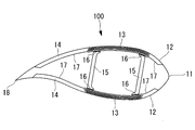
- the windmill rotor blade 100 includes an outer skin material 11, a front edge sandwich material 12, a spar cap material (main strength material) 13, a rear edge sandwich material 14, and a shear web (girder material) 15 which will be described later.
- the leading edge sandwich material 12 and the trailing edge sandwich material 14 have a sandwich structure in which the outer skin material 11 and the inner skin material 17 are skin materials, and a resin foam such as PVC or wood such as balsa is a core material.
- symbol 16 in FIG. 5 is the adhesive agent which connects the spar cap material 13 and the shear web 15 (connection).
- each member constituting the wind turbine rotor blade 100 (more specifically, the outer skin material 11, the front edge sandwich material 12, the spar cap material 13, the rear edge sandwich material 14, and the shear web 15). If the safety factor and the buckling strength safety factor can be set to the same level (for example, 2), the wind turbine rotor blade can be further reduced in weight.
- the width of the spar cap material 13 (cord direction (in FIG. 5)
- the spar cap material 13 is made thick while the length) in the left-right direction) is narrowed, and the gap between the shear webs 15 (the distance between the shear web 15 located on the front edge side and the shear web 15 located on the rear edge side) is narrowed. That's fine.
- the width of the trailing edge sandwich material 14 (length in the cord direction (left and right direction in FIG. 5)) is increased, and the buckling strength of the trailing edge sandwich material 14 with respect to the load in the edge direction is further reduced. There was a problem.
- the present invention has been made in view of the above circumstances, can improve the buckling strength against the load in the edge direction, can bring the safety factor of buckling strength closer to the safety factor of material strength, and further
- An object of the present invention is to provide a wind turbine rotor blade and a wind turbine for wind power generation that can be reduced in weight.
- the present invention employs the following means in order to solve the above problems.
- the wind turbine rotor blade according to the first aspect of the present invention includes a skin material formed of fiber-reinforced plastic, a sheer web, and a trailing edge sandwich material disposed on the trailing edge side of the trailing edge of the beam.
- a reinforcing material is provided on the inner surface of the outer skin material on the ventral side located on the rear edge side of the rear edge of the rear edge sandwich material.
- the reinforcing material in which the plate thickness of the outer skin material located on the rear edge side of the rear edge end of the rear edge sandwich material is disposed on the inner surface thereof. Therefore, the bending stiffness in the edge direction at the trailing edge can be improved, the buckling strength against the load in the edge direction at the trailing edge can be improved, and the safety factor of the buckling strength. Can be made close to the safety factor of material strength, and further weight reduction can be achieved. Further, according to the wind turbine rotor blade according to the first aspect of the present invention, the reinforcing material is attached to the inner surface of the abdominal skin material located on the rear edge side with respect to the rear edge end of the rear edge sandwich material.
- the reinforcing material can be made thinner than when the reinforcing material is attached to the inner surface of the outer skin material on the back side, and interference between the upper surface of the reinforcing material and the inner surface of the outer skin material can be easily avoided.
- the lowest-order buckling mode with respect to the load in the edge direction is the outer edge material positioned on the trailing edge side from the trailing edge of the trailing edge sandwich material or the trailing edge sandwich material.
- the Euler buckling of the reinforcing material may become the lowest buckling mode. is there.
- the same cross-sectional shape of the reinforcing material is installed only on the back side and only on the abdomen side
- the buckling strength is lower when installed on the dorsal side than on the ventral side due to the influence of curvature. Therefore, it is possible to make the reinforcing material thinner when the reinforcing material is installed on the ventral side than when the reinforcing material is installed on the back side, and it is easier to avoid interference between the upper surface of the reinforcing material and the inner surface of the outer skin material.
- the reinforcing material includes a lightweight core material, an upper surface side skin material disposed on an upper surface side of the lightweight core material, and a lower surface side skin material disposed on a lower surface side of the lightweight core material.
- the upper surface side skin material and / or the lower surface side skin material is more preferably formed of fiber reinforced plastic in which reinforcing fibers are oriented in the longitudinal direction of the blade.
- the reinforcing fibers constituting the upper surface side skin material and / or the lower surface side skin material are arranged along the blade longitudinal direction, the bending rigidity in the edge direction at the trailing edge portion is increased.
- the buckling strength against the load in the edge direction at the trailing edge can be further improved, the safety factor of buckling strength can be made closer to the safety factor of material strength, and further weight reduction Can be achieved.
- the wind turbine for wind power generation according to the second aspect of the present invention can improve the bending rigidity in the edge direction at the trailing edge, and can improve the buckling strength against the load in the edge direction at the trailing edge.
- the windmill rotor blade is provided that can make the safety factor of buckling strength close to the safety factor of material strength and can further reduce the weight.
- the rotary shaft that connects the rotor head and the root portion of the wind turbine rotor blade, or the connecting shaft that is installed in the rotor head and gives the wind turbine blade rotational motion can be reduced, and the load applied to the tower that supports the wind turbine rotor blades and the rotor head can be reduced.
- the buckling strength against the load in the edge direction can be improved, the safety factor of the buckling strength can be brought close to the safety factor of the material strength, and further weight reduction is achieved. There is an effect that can be.
- FIG. 1 is a side view showing a wind turbine for wind power generation provided with a wind turbine rotor blade according to the present embodiment
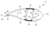
- FIG. 2 is a cross-sectional view of the wind turbine rotor blade according to the present embodiment
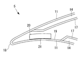
- FIG. 3 is an enlarged cross-sectional view of the main part of FIG. FIG.
- a wind turbine 1 for wind power generation includes a column (also referred to as “tower”) 2 standing on a foundation B, a nacelle 3 installed at the upper end of the column 2, and a substantially horizontal axis. And a rotor head 4 provided on the nacelle 3 so as to be rotatable around.
- a plurality of (for example, three) wind turbine rotor blades 5 are attached to the rotor head 4 in a radial pattern around the rotation axis. As a result, the force of the wind striking the wind turbine rotor blade 5 from the direction of the rotation axis of the rotor head 4 is converted into power for rotating the rotor head 4 around the rotation axis.
- the support column 2 is configured by connecting a plurality of (for example, three) units (not shown) vertically.
- the nacelle 3 is installed on a unit provided at the uppermost part of the units constituting the column 2, and a nacelle base plate (not shown) attached to the upper end of the column 2 and the nacelle base plate And a cover 6 covering from above.
- the wind turbine rotor 5 has a spar cap structure that satisfies both requirements of lightness and strength, and includes a skin material 11, a leading edge sandwich material 12, a spar cap material (main strength material). ) 13, a trailing edge sandwich material 14, and a sheer web (girder) 15.
- the outer skin material 11, the spar cap material 13, and the endothelial material 17 are each formed (configured) of fiber reinforced plastic (FRP).
- the spar cap material 13 is a member in which fiber reinforced plastics are laminated in multiple layers, and is in contact with the back surface (upper side in FIG. 2) and the abdominal side (lower side in FIG. 2) of the shear web 15 One is provided on each of the back side and the ventral side of the rotary blade 5. Further, the spar cap material 13 and the shear web 15 are connected (coupled) via an adhesive 16 that cures at room temperature.
- Each of the leading edge sandwich material 12 and the trailing edge sandwich material 14 has a sandwich structure in which the outer skin material 11 and the inner skin material 17 are skin materials, and a resin foam such as PVC or a wood material such as balsa is a core material. Yes. Further, the leading edge sandwich material 12 and the trailing edge sandwich material 14 are sandwiched between the outer skin material 11 and the inner skin material 17, respectively.
- the bending strength in the flap direction of the wind turbine rotor 5 is maintained mainly by the spar cap material 13 formed of fiber reinforced plastic, and the leading edge sandwich material 12 and the trailing edge sandwich material 14 are maintained. Is used auxiliary to maintain the buckling strength of the wind turbine rotor 5.
- the reinforcing material 20 is provided on the inner surface 19 of the abdominal skin material 11 located on the rear edge 18 side with respect to the rear edge end of the rear edge sandwich material 14. Is (arranged).
- the reinforcing member 20 is a fiber reinforcement in which reinforcing fibers (not shown) are oriented in the longitudinal direction of the wind turbine rotor 5 (the direction perpendicular to the paper surface in FIGS. 2 and 3).
- It is a member in which plastics are laminated in multiple layers (for example, 20 layers) and the thickness thereof is about 20 mm, and is connected (connected) to the inner surface 19 of the skin material 11 on the ventral side via an adhesive 21 that cures at room temperature. )
- the plate thickness of the skin material 11 on the abdominal side located on the rear edge 18 side with respect to the rear edge end of the rear edge sandwich material 14 is disposed on the inner surface 19 thereof. Since it is increased by the reinforcing material 20, the bending rigidity in the edge direction at the rear edge can be improved, the buckling strength against the load in the edge direction at the rear edge can be improved, and the buckling strength can be improved. The safety factor can be made closer to the safety factor of the material strength, and further weight reduction can be achieved. As a result, even if the width of the trailing edge sandwich material 14 (length in the cord direction (left and right direction in FIG.
- the distance between the shear webs 15 in the cord direction that is, the distance between the shear web 15 located on the front edge side and the shear web 15 located on the rear edge side can be narrowed, and the width of the spar cap material 13 is narrowed ( At this time, it is possible to increase the thickness of the spar cap material 13 while maintaining the same cross-sectional area of the spar cap material 13), and to improve the buckling strength of the spar cap material 13 against the load in the flap direction.
- the reinforcing member 20 is attached only to the inner surface 19 of the abdominal skin material 11 located on the trailing edge 18 side with respect to the trailing edge end of the trailing edge sandwich material 14. Therefore, it is possible to make the reinforcing material thinner than when the reinforcing material is attached only to the inner surface of the outer skin material on the back side, and the interference between the upper surface of the reinforcing material and the inner surface of the outer skin material is reduced. Easy to avoid.
- the lowest-order buckling mode with respect to the load in the edge direction is the outer edge material positioned on the trailing edge side from the trailing edge of the trailing edge sandwich material or the trailing edge sandwich material.
- the Euler buckling of the reinforcing material may become the lowest buckling mode. is there.
- the reinforcing material is too thick, interference with the inner surface of the outer skin material occurs, so it is desirable to make it as thin as possible.
- the same cross-sectional shape of the reinforcing material is installed only on the back side and only on the abdomen side
- the buckling strength is lower when installed on the dorsal side than on the ventral side due to the influence of curvature.
- the reinforcing fibers constituting the reinforcing member 20 are arranged along the blade longitudinal direction, so that the bending rigidity in the edge direction at the trailing edge portion is further improved.
- the buckling strength against the load in the edge direction at the trailing edge can be further improved, the safety factor of the buckling strength can be made closer to the safety factor of the material strength, and the weight can be further reduced. be able to.
- the wind turbine blade is installed in a rotary bearing or rotor head that connects the rotor head and the root portion of the wind turbine rotor blade. It is possible to reduce the weight of a connecting shaft (not shown) that imparts rotational motion, and to reduce the load applied to the tower 2 that supports the wind turbine rotor 5 and the rotor head 4.
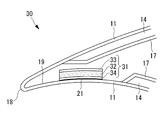
- FIG. 4 is an enlarged cross-sectional view of the main part of the wind turbine rotor blade according to the present embodiment, which is the same as FIG.
- the windmill rotor blade 30 according to the present embodiment is different from that of the first embodiment described above in that a reinforcing material 31 is provided instead of the reinforcing material 20. Since other components are the same as those of the first embodiment described above, description of these components is omitted here.
- symbol is attached
- the reinforcing material 31 includes a lightweight core material 32, a skin material 33 disposed on the upper surface side of the lightweight core material 32 (upper surface side), and a lower surface side of the lightweight core material 32. And a skin material 34 (on the lower surface side).
- the lightweight core material 32 is formed (configured) of a resin foam such as PVC or wood such as balsa, and is sandwiched between the skin material 33 and the skin material 34.
- Each of the skin materials 33 and 34 has the same length as the length in the cord direction (left and right direction in FIG. 4) of the corresponding (opposing) end face of the lightweight core material 32.
- Each of the skin materials 33 and 34 is formed (configured) of fiber reinforced plastic in which reinforcing fibers (not shown) are oriented in the longitudinal direction of the wind turbine rotor 30 (direction perpendicular to the paper surface in FIG. 4). Yes.
- the skin material 33 is bonded to the end surface on the upper surface side of the lightweight core material 32, the skin material 34 is bonded to the end surface on the lower surface side of the lightweight core material 32, and the lightweight core material 32 and the skin materials 33 and 34 are It is integrally formed (configured). Further, the inner surface 19 of the skin material 11 on the ventral side and the skin material 34 are connected (coupled) via an adhesive 23 that cures at room temperature.
- the reinforcing member 31 since the reinforcing member 31 has a sandwich structure in which the lightweight core member 32 is sandwiched between the skin member 33 and the skin member 34, the weight of the reinforcing member 31 can be reduced.
- the entire windmill rotor blade 30 can be reduced in weight, the bending rigidity in the edge direction at the trailing edge can be improved, and the buckling strength against the load in the edge direction at the trailing edge can be improved.
- the safety factor of buckling strength can be brought close to the safety factor of material strength, and further weight reduction can be achieved.
- Other functions and effects are the same as those of the first embodiment described above, and thus the description thereof is omitted here.
- both of the reinforcing members 20 and 31 can be applied not only to the wind turbine rotor blade having the structure shown in FIG. 5 but also to a wind turbine rotor blade provided with a shear web having a box structure.
- Windmill for wind power generation Strut (tower) 3 Nacelle 4 Rotor head 5 Wind turbine rotor 6 Nacelle cover 11 Skin material 12 Front edge sandwich material 13 Spar cap material (main strength material) 14 Trailing edge sandwich material 15 Shear web (girder) 16 Adhesive 17 Endothelial material 18 Trailing edge 19 Inner surface 20 Reinforcement material 30 Windmill rotor blade 31 Reinforcement material 32 Lightweight core material 33 Skin material (upper surface side skin material) 34 Skin material (underside skin material) 100 windmill rotor blade B basic
Landscapes
- Engineering & Computer Science (AREA)
- Life Sciences & Earth Sciences (AREA)
- Sustainable Development (AREA)
- Sustainable Energy (AREA)
- Chemical & Material Sciences (AREA)
- Combustion & Propulsion (AREA)
- Mechanical Engineering (AREA)
- General Engineering & Computer Science (AREA)
- Wind Motors (AREA)
Abstract
Description
なお、図5中の符号16は、スパーキャップ材13とシアウェブ15とを接続(連結)する接着剤である。
しかしその反面、後縁サンドイッチ材14の幅(コード方向(図5において左右方向)の長さ)が広くなり、エッジ方向の荷重に対する後縁サンドイッチ材14の座屈強度がますます低下してしまうといった問題点があった。
本発明の第一の態様に係る風車回転翼は、繊維強化プラスチックで形成された外皮材と、シアウェブと、この桁材の後縁端よりも後縁側に配置された後縁サンドイッチ材とを有する風車回転翼であって、前記後縁サンドイッチ材の後縁端よりも後縁側に位置する腹側の外皮材の内表面に、補強材が設けられている。
また、本発明の第一の態様に係る風車回転翼によれば、後縁サンドイッチ材の後縁端よりも後縁側に位置する腹側の外皮材の内表面に補強材が取り付けられているので、背側の外皮材の内表面に補強材が取り付けられている場合よりも、補強材を薄くすることが可能であり、補強材上面と外皮材の内表面の干渉を回避しやすい。
従来の風車回転翼では、エッジ方向の荷重に対する最低次の座屈モードは、後縁サンドイッチ材または後縁サンドイッチ材の後縁端よりも後縁側に位置する外皮材である。一方、後縁サンドイッチ材の後縁端よりも後縁側に位置する外皮材の内表面に補強材が取り付けられている場合、補強材のオイラー座屈が最低次の座屈モードになる可能性がある。補強材の断面積を維持しながら、補強材のオイラー座屈強度を後縁サンドイッチ材または後縁サンドイッチ材の後縁端よりも後縁側に位置する外皮材の座屈強度より大きくするためには、補強材の幅を狭くしつつ厚さを大きくすればよい。しかし、補強材を厚くしすぎると、外皮材の内表面との干渉が生じるので、極力薄くすることが望ましい。風車翼のような外表面形状(後縁近傍で腹側より背側のほうが平面に近い)を有しているとき、同一断面形状の補強材を背側のみに設置する場合と腹側のみに設置する場合とを比較すると、曲率の影響で腹側より背側に設置したほうが座屈強度が低くなる。したがって、腹側に補強材を設置するほうが背側に設置する場合よりも、補強材を薄くすることが可能であり、補強材上面と外皮材の内表面の干渉を回避しやすい。
図1は本実施形態に係る風車回転翼を具備した風力発電用風車を示す側面図、図2は本実施形態に係る風車回転翼の断面図、図3は図2の要部を拡大した断面図である。
ローターヘッド4には、その回転軸線周りに放射状にして複数枚(例えば、3枚)の風車回転翼5が取り付けられている。これにより、ローターヘッド4の回転軸線方向から風車回転翼5に当たった風の力が、ローターヘッド4を回転軸線周りに回転させる動力に変換されるようになっている。
また、ナセル3は、支柱2を構成するユニットのうち、最上部に設けられるユニット上に設置されており、支柱2の上端に取り付けられるナセル台板(図示せず)と、このナセル台板を上方から覆うカバー6とを有している。
そして、このようなスパーキャップ構造では、主として、繊維強化プラスチックで形成されているスパーキャップ材13によって風車回転翼5のフラップ方向の曲げ強度が保たれ、前縁サンドイッチ材12および後縁サンドイッチ材14は、風車回転翼5の座屈強度を保つために補助的に使用されている。
図2または図3に示すように、補強材20は、風車回転翼5の翼長手方向(図2および図3において紙面に垂直な方向)に強化繊維(図示せず)が配向された繊維強化プラスチックを多層(例えば、20層)に積層して、その厚みが20mm程度とされた部材であり、常温で硬化する接着剤21を介して腹側の外皮材11の内表面19に接続(連結)されている。
そして、その結果、後縁サンドイッチ材14の幅(コード方向(図2において左右方向)の長さ)が広くなっても、エッジ方向の荷重に対する後縁サンドイッチ材14の座屈強度の低下を防げるので、シアウェブ15のコード方向の間隔、すなわち、前縁側に位置するシアウェブ15と、後縁側に位置するシアウェブ15との間の距離を狭くすることができ、スパーキャップ材13の幅を狭くする(このとき、スパーキャップ材13の断面積は同等に維持しながら、スパーキャップ材13を厚くする)ことができて、フラップ方向の荷重に対するスパーキャップ材13の座屈強度を向上させることができる。
従来の風車回転翼では、エッジ方向の荷重に対する最低次の座屈モードは、後縁サンドイッチ材または後縁サンドイッチ材の後縁端よりも後縁側に位置する外皮材である。一方、後縁サンドイッチ材の後縁端よりも後縁側に位置する外皮材の内表面に補強材が取り付けられている場合、補強材のオイラー座屈が最低次の座屈モードになる可能性がある。補強材の断面積を維持しながら、補強材のオイラー座屈強度を後縁サンドイッチ材または後縁サンドイッチ材の後縁端よりも後縁側に位置する外皮材の座屈強度より大きくするためには、補強材の幅を狭くしつつ厚さを大きくすればよい。しかし、補強材を厚くしすぎると、外皮材の内表面との干渉が生じるので、極力薄くすることが望ましい。風車翼のような外表面形状(後縁近傍で腹側より背側のほうが平面に近い)を有しているとき、同一断面形状の補強材を背側のみに設置する場合と腹側のみに設置する場合とを比較すると、曲率の影響で腹側より背側に設置したほうが座屈強度が低くなる。したがって、腹側に補強材を設置するほうが背側に設置する場合よりも、補強材を薄くすることが可能であり、補強材上面と外皮材の内表面の干渉を回避しやすい。
図4は本実施形態に係る風車回転翼の要部を拡大した断面図であって、図3と同様の図である。
本実施形態に係る風車回転翼30は、補強材20の代わりに補強材31を備えているという点で上述した第1実施形態のものと異なる。その他の構成要素については上述した第1実施形態のものと同じであるので、ここではそれら構成要素についての説明は省略する。
なお、上述した実施形態と同一の部材には同一の符号を付している。
スキン材33,34はそれぞれ、軽量コア材32の対応(対向)する端面のコード方向(図4において左右方向)の長さと同じ長さを有している。また、スキン材33,34はそれぞれ、風車回転翼30の翼長手方向(図4において紙面に垂直な方向)に強化繊維(図示せず)が配向された繊維強化プラスチックで形成(構成)されている。
その他の作用効果は、上述した第1実施形態と同じであるので、ここではその説明を省略する。
例えば、補強材20,31はいずれも、図5に示す構造を有する風車回転翼のみに適用され得るものではなく、ボックス構造のシアウェブを備えた風車回転翼等にも適用することができる。
2 支柱(タワー)
3 ナセル
4 ローターヘッド
5 風車回転翼
6 ナセルカバー
11 外皮材
12 前縁サンドイッチ材
13 スパーキャップ材(主強度材)
14 後縁サンドイッチ材
15 シアウェブ(桁材)
16 接着剤
17 内皮材
18 後縁
19 内表面
20 補強材
30 風車回転翼
31 補強材
32 軽量コア材
33 スキン材(上面側スキン材)
34 スキン材(下面側スキン材)
100 風車回転翼
B 基礎
Claims (3)
- 繊維強化プラスチックで形成された外皮材と、桁材と、この桁材の後縁端よりも後縁側に配置された後縁軽量コア材とを有する風車回転翼であって、
前記後縁軽量コア材の後縁端よりも後縁側に位置する腹側の外皮材の内表面に、補強材が設けられている風車回転翼。 - 前記補強材が、軽量コア材と、この軽量コア材の上面側に配置される上面側スキン材と、前記軽量コア材の下面側に配置される下面側スキン材とを備え、
前記上面側スキン材および/または前記下面側スキン材は、翼長手方向に強化繊維が配向された繊維強化プラスチックで形成されている請求項1に記載の風車回転翼。 - 請求項1または2に記載の風車回転翼を備えてなる風力発電用風車。
Priority Applications (3)
| Application Number | Priority Date | Filing Date | Title |
|---|---|---|---|
| EP10839566.6A EP2518314B1 (en) | 2009-12-25 | 2010-12-24 | Wind turbine rotor blade and wind turbine |
| AU2010336191A AU2010336191A1 (en) | 2009-12-25 | 2010-12-24 | Wind turbine rotor blade and wind-generating wind turbine |
| US13/070,998 US8651822B2 (en) | 2009-12-25 | 2011-03-24 | Wind turbine rotor blade and wind-generating wind turbine |
Applications Claiming Priority (2)
| Application Number | Priority Date | Filing Date | Title |
|---|---|---|---|
| JP2009296152A JP5427597B2 (ja) | 2009-12-25 | 2009-12-25 | 風車回転翼 |
| JP2009-296152 | 2009-12-25 |
Related Child Applications (1)
| Application Number | Title | Priority Date | Filing Date |
|---|---|---|---|
| US13/070,998 Continuation US8651822B2 (en) | 2009-12-25 | 2011-03-24 | Wind turbine rotor blade and wind-generating wind turbine |
Publications (1)
| Publication Number | Publication Date |
|---|---|
| WO2011078337A1 true WO2011078337A1 (ja) | 2011-06-30 |
Family
ID=44195862
Family Applications (1)
| Application Number | Title | Priority Date | Filing Date |
|---|---|---|---|
| PCT/JP2010/073370 Ceased WO2011078337A1 (ja) | 2009-12-25 | 2010-12-24 | 風車回転翼および風力発電用風車 |
Country Status (5)
| Country | Link |
|---|---|
| US (1) | US8651822B2 (ja) |
| EP (1) | EP2518314B1 (ja) |
| JP (1) | JP5427597B2 (ja) |
| AU (1) | AU2010336191A1 (ja) |
| WO (1) | WO2011078337A1 (ja) |
Families Citing this family (7)
| Publication number | Priority date | Publication date | Assignee | Title |
|---|---|---|---|---|
| ES2342638B1 (es) * | 2007-02-28 | 2011-05-13 | GAMESA INNOVATION & TECHNOLOGY, S.L. | Una pala de aerogenerador multi-panel. |
| JP5427597B2 (ja) * | 2009-12-25 | 2014-02-26 | 三菱重工業株式会社 | 風車回転翼 |
| MX2012001612A (es) * | 2009-12-25 | 2012-06-01 | Mitsubishi Heavy Ind Ltd | Aspa rotatoria de molino de viento. |
| CN102927051A (zh) * | 2012-11-15 | 2013-02-13 | 江苏中联风能机械有限公司 | 改进的大型空冷轴流风机叶片 |
| US8973871B2 (en) * | 2013-01-26 | 2015-03-10 | The Boeing Company | Box structures for carrying loads and methods of making the same |
| KR101678015B1 (ko) * | 2014-12-30 | 2016-11-21 | 한국에너지기술연구원 | 국부 보강 구조를 갖는 복합재 블레이드 |
| DE102016007675A1 (de) * | 2016-06-24 | 2017-12-28 | Senvion Gmbh | Hinterkantengurt mit Rechteckquerschnitt |
Citations (5)
| Publication number | Priority date | Publication date | Assignee | Title |
|---|---|---|---|---|
| US4976587A (en) * | 1988-07-20 | 1990-12-11 | Dwr Wind Technologies Inc. | Composite wind turbine rotor blade and method for making same |
| JP2002137307A (ja) * | 2000-11-02 | 2002-05-14 | Toray Ind Inc | 繊維強化樹脂製風車ブレード構造体 |
| JP2007255366A (ja) * | 2006-03-24 | 2007-10-04 | Mitsubishi Heavy Ind Ltd | 風車翼 |
| WO2008086805A2 (en) | 2007-01-16 | 2008-07-24 | Danmarks Tekniske Universitet | Reinforced blade for wind turbine |
| US20090140527A1 (en) * | 2007-11-30 | 2009-06-04 | General Electric Company | Wind turbine blade stiffeners |
Family Cites Families (14)
| Publication number | Priority date | Publication date | Assignee | Title |
|---|---|---|---|---|
| JP3825346B2 (ja) * | 2001-03-27 | 2006-09-27 | 三菱重工業株式会社 | 風力発電装置用複合材ブレード |
| ES2574779T5 (es) * | 2001-07-19 | 2022-02-17 | Vestas Wind Sys As | Alabe para aerogenerador |
| NL1024463C2 (nl) * | 2003-10-06 | 2005-04-07 | Polymarin Holding B V | Rotor voor gebruik in een windturbine en werkwijze voor het maken van de rotor. |
| BRPI0520633A2 (pt) * | 2005-11-03 | 2009-05-19 | Vestas Wind Sys As | pá de turbina eólica, turbina eólica, meio de amortecimento de oscilações para amortecimento de oscilações ou vibrações entre bordas de uma pá de turbina eólica, método de amortecimento de oscilações de uma pá de turbina eólica, e uso de um meio de amortecimento de oscilações em uma pá de turbina eólica |
| BRPI0822646A2 (pt) * | 2008-06-05 | 2016-07-05 | Mitsubishi Heavy Ind Ltd | pá de turbina eólica formada de uma película plástica reforçada com fibras, e, gerador de energia eólica |
| US20100135817A1 (en) * | 2008-10-22 | 2010-06-03 | Wirt John C | Wind turbine blade and method for manufacturing thereof |
| JP2011032988A (ja) * | 2009-08-05 | 2011-02-17 | Nitto Denko Corp | 風力発電機ブレード用発泡充填材、風力発電機ブレード用発泡充填部品、風力発電機ブレード、風力発電機、および、風力発電機ブレードの製造方法 |
| JP2011032987A (ja) * | 2009-08-05 | 2011-02-17 | Nitto Denko Corp | 風力発電機ブレード用補強シート、風力発電機ブレードの補強構造、風力発電機および風力発電機ブレードの補強方法 |
| US8702397B2 (en) * | 2009-12-01 | 2014-04-22 | General Electric Company | Systems and methods of assembling a rotor blade for use in a wind turbine |
| JP5308323B2 (ja) * | 2009-12-22 | 2013-10-09 | 三菱重工業株式会社 | 風車翼及びそれを用いた風力発電装置 |
| JP5484892B2 (ja) * | 2009-12-25 | 2014-05-07 | 三菱重工業株式会社 | 風車回転翼 |
| MX2012001612A (es) * | 2009-12-25 | 2012-06-01 | Mitsubishi Heavy Ind Ltd | Aspa rotatoria de molino de viento. |
| JP5427597B2 (ja) * | 2009-12-25 | 2014-02-26 | 三菱重工業株式会社 | 風車回転翼 |
| US8142164B2 (en) * | 2009-12-31 | 2012-03-27 | General Electric Company | Rotor blade for use with a wind turbine and method for assembling rotor blade |
-
2009
- 2009-12-25 JP JP2009296152A patent/JP5427597B2/ja not_active Expired - Fee Related
-
2010
- 2010-12-24 AU AU2010336191A patent/AU2010336191A1/en not_active Abandoned
- 2010-12-24 WO PCT/JP2010/073370 patent/WO2011078337A1/ja not_active Ceased
- 2010-12-24 EP EP10839566.6A patent/EP2518314B1/en not_active Not-in-force
-
2011
- 2011-03-24 US US13/070,998 patent/US8651822B2/en not_active Expired - Fee Related
Patent Citations (5)
| Publication number | Priority date | Publication date | Assignee | Title |
|---|---|---|---|---|
| US4976587A (en) * | 1988-07-20 | 1990-12-11 | Dwr Wind Technologies Inc. | Composite wind turbine rotor blade and method for making same |
| JP2002137307A (ja) * | 2000-11-02 | 2002-05-14 | Toray Ind Inc | 繊維強化樹脂製風車ブレード構造体 |
| JP2007255366A (ja) * | 2006-03-24 | 2007-10-04 | Mitsubishi Heavy Ind Ltd | 風車翼 |
| WO2008086805A2 (en) | 2007-01-16 | 2008-07-24 | Danmarks Tekniske Universitet | Reinforced blade for wind turbine |
| US20090140527A1 (en) * | 2007-11-30 | 2009-06-04 | General Electric Company | Wind turbine blade stiffeners |
Also Published As
| Publication number | Publication date |
|---|---|
| US20110171035A1 (en) | 2011-07-14 |
| EP2518314A1 (en) | 2012-10-31 |
| JP2011137388A (ja) | 2011-07-14 |
| JP5427597B2 (ja) | 2014-02-26 |
| AU2010336191A1 (en) | 2012-01-19 |
| US8651822B2 (en) | 2014-02-18 |
| EP2518314B1 (en) | 2018-06-27 |
| EP2518314A4 (en) | 2014-05-28 |
Similar Documents
| Publication | Publication Date | Title |
|---|---|---|
| JP5536103B2 (ja) | 風車回転翼 | |
| JP5484892B2 (ja) | 風車回転翼 | |
| CN102465826B (zh) | 用于风机转子叶片的主梁帽组件 | |
| JP5427597B2 (ja) | 風車回転翼 | |
| WO2011078327A1 (ja) | 風車回転翼および風車回転翼の製造方法 | |
| JP2011137386A5 (ja) | ||
| US8186964B2 (en) | Spar assembly for a wind turbine rotor blade | |
| JP2011137388A5 (ja) | ||
| KR20110100192A (ko) | 풍력 터빈 날개 및 이를 사용하는 풍력 터빈 발전장치 | |
| EP2159414B1 (en) | Wind turbine blades with cross webs | |
| CN114630959B (zh) | 风力涡轮机叶片 | |
| CN114630957A (zh) | 风力涡轮机叶片 | |
| EP2526287B1 (en) | A wind turbine rotor blade having a buckling trailing edge | |
| US12503996B2 (en) | Wind turbine blade with leeward reinforcement structures and windward reinforcement structures | |
| JP2019218886A (ja) | 風車用ブレード及び風力発電装置 | |
| JP2020084812A (ja) | 風車用ブレードおよび風力発電装置 | |
| KR102719754B1 (ko) | 풍력발전기의 블레이드 | |
| JP2024062016A (ja) | 風車翼 | |
| JP2005147080A (ja) | 水平軸風車のブレード | |
| CN118242214A (zh) | 风轮机叶片 |
Legal Events
| Date | Code | Title | Description |
|---|---|---|---|
| 121 | Ep: the epo has been informed by wipo that ep was designated in this application |
Ref document number: 10839566 Country of ref document: EP Kind code of ref document: A1 |
|
| WWE | Wipo information: entry into national phase |
Ref document number: 2010336191 Country of ref document: AU |
|
| WWE | Wipo information: entry into national phase |
Ref document number: 2010839566 Country of ref document: EP |
|
| ENP | Entry into the national phase |
Ref document number: 2010336191 Country of ref document: AU Date of ref document: 20101224 Kind code of ref document: A |
|
| NENP | Non-entry into the national phase |
Ref country code: DE |