WO2011081050A1 - 電動工具 - Google Patents
電動工具 Download PDFInfo
- Publication number
- WO2011081050A1 WO2011081050A1 PCT/JP2010/072917 JP2010072917W WO2011081050A1 WO 2011081050 A1 WO2011081050 A1 WO 2011081050A1 JP 2010072917 W JP2010072917 W JP 2010072917W WO 2011081050 A1 WO2011081050 A1 WO 2011081050A1
- Authority
- WO
- WIPO (PCT)
- Prior art keywords
- electric motor
- time
- braking
- rotation speed
- electric
- Prior art date
- Legal status (The legal status is an assumption and is not a legal conclusion. Google has not performed a legal analysis and makes no representation as to the accuracy of the status listed.)
- Ceased
Links
Images



Classifications
-
- B—PERFORMING OPERATIONS; TRANSPORTING
- B25—HAND TOOLS; PORTABLE POWER-DRIVEN TOOLS; MANIPULATORS
- B25F—COMBINATION OR MULTI-PURPOSE TOOLS NOT OTHERWISE PROVIDED FOR; DETAILS OR COMPONENTS OF PORTABLE POWER-DRIVEN TOOLS NOT PARTICULARLY RELATED TO THE OPERATIONS PERFORMED AND NOT OTHERWISE PROVIDED FOR
- B25F5/00—Details or components of portable power-driven tools not particularly related to the operations performed and not otherwise provided for
- B25F5/001—Gearings, speed selectors, clutches or the like specially adapted for rotary tools
-
- A—HUMAN NECESSITIES
- A01—AGRICULTURE; FORESTRY; ANIMAL HUSBANDRY; HUNTING; TRAPPING; FISHING
- A01D—HARVESTING; MOWING
- A01D34/00—Mowers; Mowing apparatus of harvesters
- A01D34/835—Mowers; Mowing apparatus of harvesters specially adapted for particular purposes
- A01D34/90—Mowers; Mowing apparatus of harvesters specially adapted for particular purposes for carrying by the operator
-
- H—ELECTRICITY
- H02—GENERATION; CONVERSION OR DISTRIBUTION OF ELECTRIC POWER
- H02P—CONTROL OR REGULATION OF ELECTRIC MOTORS, ELECTRIC GENERATORS OR DYNAMO-ELECTRIC CONVERTERS; CONTROLLING TRANSFORMERS, REACTORS OR CHOKE COILS
- H02P29/00—Arrangements for regulating or controlling electric motors, appropriate for both AC and DC motors
- H02P29/10—Arrangements for regulating or controlling electric motors, appropriate for both AC and DC motors for preventing overspeed or under speed
-
- H—ELECTRICITY
- H02—GENERATION; CONVERSION OR DISTRIBUTION OF ELECTRIC POWER
- H02P—CONTROL OR REGULATION OF ELECTRIC MOTORS, ELECTRIC GENERATORS OR DYNAMO-ELECTRIC CONVERTERS; CONTROLLING TRANSFORMERS, REACTORS OR CHOKE COILS
- H02P3/00—Arrangements for stopping or slowing electric motors, generators, or dynamo-electric converters
- H02P3/06—Arrangements for stopping or slowing electric motors, generators, or dynamo-electric converters for stopping or slowing an individual dynamo-electric motor or dynamo-electric converter
Definitions
- the present invention relates to an electric tool.
- a conventional brush cutter includes a battery, an electric motor, and a cutter (for example, a cutting blade or a nylon cord cutter), and the cutter is connected to a driving shaft of the electric motor via a driving force transmission mechanism (that is, a gear, a transmission shaft, or the like). Connected to each other.
- a driving force transmission mechanism that is, a gear, a transmission shaft, or the like.
- Patent Document 1 discloses the use of regenerative braking.
- regenerative braking energization of the coil of the motor is interrupted and both ends of the coil are short-circuited, so that a large braking force is generated on the rotor of the motor. That is, when regenerative braking is used, the rotation of the rotor, and hence the rotation of the cutter, can be stopped abruptly.
- an object of the present invention is to provide an electric tool that can suppress a decrease in the feeling of use of the electric tool due to braking of the electric motor.
- an electric tool includes an electric motor, a rotation speed detection means, a braking means, and a rotation speed reference operation means.
- the electric motor generates a driving force for rotating the drive target
- the rotation speed detecting means detects the rotation speed of the electric motor.
- the rotation speed reference operation means is The braking means is operated, and the braking means executes braking control for braking the electric motor.
- the braking control is executed after the rotation speed of the electric motor is reduced, that is, the kinetic energy of the rotating drive target is reduced. For this reason, in this electric tool, since the electric motor is braked after the rotational speed of the electric motor is reduced to the specified rotational speed, the reaction applied to the electric tool by the braking of the electric motor can be reduced. That is, with this electric power tool, it is possible to suppress a decrease in feeling of use due to braking of the electric motor.
- the electric power tool of the present invention may include a time reference actuating unit that activates the braking unit when a braking control start time that is an arbitrarily set time period has elapsed after the stop command is issued.
- the braking control can be executed after an arbitrarily set time has elapsed since the stop command was issued.
- the specified rotational speed may be set according to the usage status of the power tool.
- the electric tool of the present invention may include a specified speed setting unit that sets a specified rotation speed.
- the electric power tool of the present invention may further include a reduction rate deriving unit that sequentially derives a reduction rate that is a rate at which the rotation speed of the electric motor decreases in a unit period based on the detection result of the rotation speed detection unit.
- the prescribed speed defining means may be configured to set the prescribed rotational speed based on the decrease rate derived by the decrease rate deriving means.
- the prescribed speed setting means may set a larger value as the prescribed rotational speed as the decrease rate is larger.
- the electric motor may be configured to be rotatable in the forward rotation direction and the reverse rotation direction.
- the specified speed setting means sets individual specified rotation speeds for the normal rotation direction and the reverse rotation direction, respectively. Good.
- the specified speed setting means is configured in this way, appropriate specified rotation speeds can be individually set in the forward direction and the reverse direction.
- the braking control start time may be set according to the usage status of the power tool.
- the electric power tool of the present invention is preferably provided with time setting means for setting the braking control start time.
- the electric power tool of the present invention may further include a reduction rate deriving unit that sequentially derives a reduction rate, which is a rate at which the rotation speed of the electric motor decreases in a unit period, based on the detection result of the rotation speed detection unit.
- the time setting unit may be configured to set the braking control start time based on the decrease rate derived by the decrease rate deriving unit.
- the time setting means preferably sets the shorter time length as the braking control start time as the decrease rate is larger.
- the electric power tool of the present invention further includes a rotation speed command switch for setting a command value for the rotation speed of the electric motor, and command value acquisition means for acquiring the command value set by the rotation speed command switch.
- the time setting means is based on the off-time rotation speed, which is the rotation speed when the command value acquired by the command value acquisition means falls within a stop range that is considered to be commanded to stop the motor.
- the braking control start time may be set.
- the braking control start time can be set according to the usage state of the electric tool when the rotation of the electric motor is to be stopped.
- the time setting means sets a longer time length as the braking control start time as the off-time rotation speed increases.
- the power tool may include a sensor that directly detects the off-time rotation speed, or may include an estimation unit that estimates the off-time rotation speed based on the command value acquired by the command value acquisition unit. Good.
- the estimation unit preferably estimates the off-time rotation speed as a larger value as the value of the command value before the specified time before the command value falls within the stop range is larger.
- the drive target may be selected from a plurality of types of drive targets, and the power tool may be configured so that a selected one of the plurality of types of drive targets can be mounted.
- the time setting means may be configured to set a braking control start time corresponding to a driving object having the maximum inertia among a plurality of types of driving objects as a braking control start time of the electric tool. .
- the time setting means is configured in this way, the braking of the electric motor is started so as to suppress the reaction caused by the braking of the electric motor, regardless of which of the plural types of driving objects is attached to the electric tool. Can do.
- the electric motor may be configured to be rotatable in the forward rotation direction and the reverse rotation direction.
- the time setting means sets individual braking control start times for the normal rotation and the reverse rotation. It should be configured.
- the time setting means is configured in this way, it is possible to individually set appropriate braking control start times in the forward direction and the reverse direction. For example, when the electric tool is configured such that the rotational speed in the reverse rotation direction is lower than that in the normal rotation direction, the braking control start time in the reverse rotation direction is shorter than the braking control start time in the normal rotation direction. It is preferable that the time length is set.
- the brake control start time for the reverse rotation direction is set to a value smaller than the brake control start time for the normal rotation direction, even when the motor is rotated in the reverse rotation direction, the brake control is performed at a more appropriate timing. Can be executed.
- the electric power tool of the present invention may include a driving force transmission mechanism that transmits the driving force of the electric motor to the driving target.
- a driving force transmission mechanism that transmits the driving force of the electric motor to the driving target.
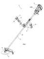
- the electric power tool 1 is configured as a so-called brush cutter that cuts grass and small-diameter trees, and includes a shaft pipe 2, a motor unit 3, and a cutter 4.
- the shaft pipe 2 is formed in the shape of a hollow bar.
- a motor unit 3 is provided at one end of the shaft pipe 2, and a cutter 4 is detachably provided at the other end of the shaft pipe 2.
- an end portion where the motor unit 3 is provided is referred to as an upper end, and an end portion where the cutter 4 is provided is referred to as a lower end.
- the cutter 4 is formed in a substantially disc shape as a whole. More specifically, the central portion of the cutter 4 is formed of a material having a rigidity equal to or higher than a predetermined value (for example, a metal material or a high-hardness synthetic resin), and is formed into a disk shape or a cylindrical shape. Has been.
- a predetermined value for example, a metal material or a high-hardness synthetic resin
- a plurality of blades (not shown) are provided on the periphery of the cutter 4.
- the plurality of blades may be a thin plate formed of the same material as the central portion of the cutter 4 or a different material, or a resin cord (so-called nylon cord) formed of a synthetic resin in a linear shape. Also good.
- a handle 8 is provided in the vicinity of an intermediate position in the axial direction of the shaft pipe 2.
- the handle 8 is provided with a right hand grip 9 for the user of the electric tool 1 to hold with the right hand and a left hand grip 10 for the user to hold with the left hand.
- the right hand grip 9 is provided with a lock-off switch 11, a trigger switch 12, and a forward / reverse selector switch 13 (see FIG. 2).
- the motor unit 3 includes a battery 7 and an electric motor 18.
- the battery 7 includes a rechargeable secondary battery (for example, a lithium ion secondary battery) inside the battery 7.
- the battery 7 is configured to be detachable from the motor unit 3.
- a driving force transmission shaft (hereinafter abbreviated as a transmission shaft) 21 is accommodated in the shaft pipe 2.
- the transmission shaft 21 is coupled to the drive shaft of the electric motor 18 on the upper end side of the transmission shaft 21, and is coupled to the cutter 4 via the gear portion 6 including a plurality of gears on the lower end side of the transmission shaft 21. .
- the electric power tool 1 includes the above-described electric motor 18, a bridge circuit 20, six gate circuits 31 to 36, and a control circuit 14.
- the electric motor 18 is configured as a well-known three-phase brushless DC motor, and the rotor of the electric motor 18 rotates when current is sequentially supplied to the coils of the respective phases U, V, and W.
- the electric motor 18 in the first embodiment includes a position detection unit 17 for detecting the rotation angle of the rotor.
- the position detection unit 17 includes a known Hall element.
- the coils of the phases U, V, and W of the electric motor 18 are connected to the battery 7 via the bridge circuit 20.
- the bridge circuit 20 is a well-known three-phase bridge circuit including six switching elements Q1 to Q6.
- a set of switching elements Q1 and Q4 connected in series, a set of switching elements Q2 and Q5 connected in series, and a set of switching elements Q3 and Q6 connected in series are connected to the battery 7.
- the positive and negative electrodes are connected in parallel to each other.
- the coils of the respective phases U, V, W of the electric motor 18 are connected between the switching elements Q1, Q4, between the switching elements Q2, Q5, and between the switching elements Q3, Q6.
- the bridge circuit 20 is configured to be able to drive the rotor of the electric motor 18 in either the forward rotation direction or the reverse rotation direction by appropriately controlling on / off of the switching elements Q1 to Q6.
- the forward rotation direction here is a direction in which the cutter 4 is rotated when cutting grass or a small-diameter tree.
- the reverse rotation direction is the reverse rotation direction, which is a rotation direction used when removing grass or the like entangled with the cutter 4.
- the electric power tool 1 of the first embodiment is configured such that the rotational speed in the reverse rotation direction is lower than that in the normal rotation direction.
- the gate circuits 31 to 36 are configured to appropriately turn on / off the switching elements Q1 to Q6 of the bridge circuit 20 in accordance with drive signals input from the control circuit 14 to the gate circuits 31 to 36, respectively. .
- the control circuit 14 includes a known microcomputer 14A including a CPU, a memory, an I / O, and the like.
- a constant voltage power supply circuit (Reg) 15 is connected to the control circuit 14, and the control circuit 14 reduces a DC voltage (for example, 36 VDC) of the battery 7 at the Reg 15 and generates a predetermined control voltage Vcc. (For example, 5 VDC).
- the control circuit 14 is connected to the lock-off switch 11, the trigger switch 12, and the forward / reverse selector switch 13.
- the lock-off switch 11 is a switch for preventing a user of the electric power tool 1 from driving the electric motor 18 by mistake. More specifically, when the lock-off switch 11 is turned off, the logic level of the voltage of the signal (drive inhibition signal) input from the lock-off switch 11 to the control circuit 14 is set to a low level (that is, the electric motor On the other hand, when the lock-off switch 11 is turned on, the logic level of the voltage of the drive inhibition signal is set to a high level (the drive of the electric motor 18 is permitted).
- the forward / reverse selector switch 13 is a switch for the user of the electric power tool 1 to set the rotation direction of the rotor of the electric motor 18 to either the forward rotation direction or the reverse rotation direction.
- the forward / reverse selector switch 13 When the forward / reverse selector switch 13 is turned off, the logic level of the voltage of the signal (forward signal) input from the forward / reverse selector switch 13 to the control circuit 14 is set to a low level, whereas the forward / reverse selector switch When 13 is turned on, the logical level of the voltage of the normal rotation signal is set to a high level.
- the trigger switch 12 includes a contact switch 12A and a variable resistor 12B.
- the trigger switch 12 includes a signal (operation signal) indicating whether or not the trigger switch 12 is pulled, and an operation amount (subtraction allowance) of the trigger switch 12. ) To output a signal (speed command value Cv) having a voltage corresponding to the control circuit 14.
- the memory of the microcomputer 14A stores various processing programs to be executed by the microcomputer 14A.
- a current having a magnitude corresponding to the speed command value Cv is supplied to the coils of the phases U, V, and W of the electric motor 18 and a predetermined specified condition is set.
- the gate circuits 31 to 36 are controlled so that a braking force is applied to the rotor of the electric motor 18.
- the memory of the microcomputer 14A stores various threshold values Th necessary for determining whether or not the specified conditions are met. That is, the control circuit 14 rotates the rotor of the electric motor 18 at a rotation speed corresponding to the speed command value Cv from the trigger switch 12 when both the lock-off switch 11 and the trigger switch 12 are turned on. The drive signal is output to each gate circuit 31-36. ⁇ Processing in control circuit> Hereinafter, processing executed by the control circuit 14 (more precisely, the microcomputer 14A) will be described.
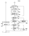
- the main routine shown in FIG. 3 is started when the lock-off switch 11 is turned on, but when the battery 7 is attached to the electric tool 1 or when the trigger switch 12 is pulled. May be started.
- the trigger switch detection process (S100) and the electric motor drive process (S102) are repeatedly and sequentially executed.
- the speed command value Cv input from the trigger switch 12 is detected. More specifically, the resistance value of the variable resistor 12B varies depending on the operation amount of the user operating the trigger switch 12, and a voltage corresponding to the resistance value is detected as the speed command value Cv.
- the speed command value Cv detected in the trigger switch detection process (S100) is less than a specified value Thv that is a predetermined threshold value. Determine (S110).
- the specified value Thv is a very small speed command value Cv that can be regarded as the trigger switch 12 being turned off. Therefore, if the speed command value Cv is less than the specified value Thv from 0 [V] (an example of the stop range of the present invention), the microcomputer 14A determines that a stop command for the electric motor 18 has been issued, and the gate circuit 31. Stops output of drive signals to .about.36.
- This drive control process is a known process for outputting a drive signal to the gate circuits 31 to 36 such that a current corresponding to the speed command value Cv flows through the coils of the phases U, V, and W of the electric motor 18.
- the rotor of the electric motor 18 rotates at a rotational speed (in the first embodiment, unit time (for example, 1 minute)) according to the pulling amount (that is, the operation amount) of the trigger switch 12. (Represented by the number of revolutions per revolution).
- S140 it is determined whether or not the forward rotation signal from the forward / reverse selector switch 13 is at a high level. As a result of the determination, if the normal rotation signal is at a high level (S140: YES), it is determined that the rotation direction of the rotor of the electric motor 18 is the normal rotation direction, and the process proceeds to S150.
- a specified rotational speed Th N that is a predetermined threshold value is acquired.
- the specified rotational speed Th N is set as a rotational speed at which braking should be started on the rotor of the electric motor 18.
- the rotational speed at which braking should start to be applied to the rotor when the cutter having the greatest inertia among the plurality of types of cutters that can be attached to the electric tool 1 is attached to the electric tool 1 is the specified rotational speed Th. N is set.
- the specified rotational speed Th N is individually set to a value when the rotation direction of the rotor of the electric motor 18 is the normal rotation direction and a value when the rotation direction is the reverse rotation direction.
- defining rotational speed Th N corresponding to the forward direction may be the same value as prescribed rotational speed Th N corresponding to the reverse direction may be a different value the prescribed rotational speed Th N corresponding to the reverse direction.
- a predefined braking process is executed.
- a drive signal that turns on any one of the group of switching elements Q1 to Q3 or the group of switching elements Q4 to Q6 constituting the bridge circuit 20 is output to the gate circuits 31 to 36. It is processing.
- this braking process is executed, the coils of each phase U, V, W of the electric motor 18 form a short circuit. Then, a braking force is applied to the rotor of the electric motor 18 rotating by inertia by so-called regenerative braking.
- this subroutine ends.
- the braking process is executed after waiting for the kinetic energy of the cutter 4 rotating due to inertia to decrease to a set value or less.
- the specified rotational speed Th N compared with the rotational speed N is based on the drive shaft of the electric motor 18 among the plurality of types of cutters that can be mounted on the electric tool 1 as the rotation center.
- the electric tool 1 can reduce that kinetic energy larger than expected is added to the transmission shaft and the gear in the gear part 6.
- FIG. As a result, fatigue accumulated in the transmission shaft and gear can be reduced, and the life of the transmission shaft and gear can be extended.
- the cutter 4 is an example of the driving target in the present invention
- S170 of the motor driving process is an example of the rotational speed detecting means in the present invention
- S190 is an example of the braking means in the present invention
- Yes S180 is an example of the rotational speed reference actuating means in the present invention.
- S150 and S160 are examples of the prescribed speed setting means in the present invention
- the trigger switch 12 is an example of the rotational speed command switch in the present invention
- S100 of the main routine is a command in the present invention. It is an example of a value acquisition means.
- the electric power tool described in the second embodiment is different from the electric power tool 1 described in the first embodiment only in the electric motor driving process executed by the control circuit 14. For this reason, in this 2nd Embodiment, it demonstrates centering on the electric motor drive process different from the electric tool 1 described in the said 1st Embodiment, About the structure similar to the electric tool 1 of the said 1st Embodiment, it is the same The description is abbreviate
- a drive control process is executed.
- the drive control process in the second embodiment is the same process as the drive control process described in the first embodiment. After the process of S320 is completed, the motor drive process is terminated.
- S310 determines whether the speed command value Cv is less than the specified value Thv (S310: YES). If the result of determination in S310 is that the speed command value Cv is less than the specified value Thv (S310: YES), it is determined that the trigger switch 12 has been turned off, and the process proceeds to S330. In S330, the output of the drive signal is stopped. That is, the gate circuits 31 to 36 turn off all of the switching elements Q1 to Q6 and cut off the current to the coils of the phases U, V, and W of the electric motor 18.
- S340 it is determined whether or not the forward rotation signal from the forward / reverse selector switch 13 is at a high level. As a result of the determination, if the normal rotation signal is at a high level (S340: YES), it is determined that the rotation direction of the rotor of the electric motor 18 is the normal rotation direction, and the process proceeds to S350.
- a braking start time BT (an example of the braking control start time according to the present invention) having a predetermined time length is acquired.
- the time length defined as the braking start time BT is a time length required from when the trigger switch 12 is turned off until the kinetic energy of the cutter 4 becomes equal to or less than a preset value.
- the kinetic energy which the cutter 4 has here assumes the case where the cutter 4 is rotating at the maximum speed of the electric motor 18.
- the trigger switch 12 is set until the kinetic energy of the cutter having the maximum inertia among the plurality of types of cutters that can be mounted on the electric power tool 1 falls below a set value. The length of time required after turning off is set.
- the braking start time BT when the rotation direction of the rotor of the electric motor 18 is the forward rotation direction and the braking start time BT when the rotation direction is the reverse rotation direction are individually set.
- the braking start time BT with respect to the reverse rotation direction is defined to be shorter than the braking start time BT with respect to the normal rotation direction.
- the braking start time BT corresponding to the forward rotation direction is acquired.
- the forward rotation signal from the forward / reverse selector switch 13 is at a low level as a result of the determination in S340 (S340: NO)
- the brake start time BT in the reverse direction is acquired.
- S370 it is determined whether or not the elapsed time after the trigger switch 12 is turned off is longer than the braking start time BT. As a result of the determination, if the elapsed time is longer than the braking start time BT (S370: YES), the process proceeds to S380. That is, when the brake start time BT has elapsed since the trigger switch 12 was turned off, the process proceeds to S380.
- a predefined braking process is executed.
- the braking process executed in the second embodiment is the same process as the braking process described in the first embodiment. After the process of S380 is completed, the electric motor drive process is terminated.
- the braking start time BT in the second embodiment is set as a time length required for the kinetic energy of the rotating cutter 4 to be equal to or less than a preset set value.
- the electric tool of the second embodiment is configured such that the rotational speed in the reverse rotation direction is lower than that in the normal rotation direction. For this reason, even if the rotor is rotated at the highest speed in the reverse rotation direction, the kinetic energy of the rotating cutter is smaller than when the rotor is rotated at the highest speed in the normal rotation direction.
- the braking start time BT in the reverse rotation direction is defined to be shorter than the braking start time BT in the normal rotation direction.
- the braking process can be executed at an appropriate timing even when the rotor is rotated in the reverse rotation direction.
- the braking start time BT for the reverse rotation direction may be the same as or different from the braking start time BT for the normal rotation direction.
- S370 of the electric motor driving process is an example of the time reference operating means in the present invention
- S350 and S360 are examples of the time setting means in the present invention.
- the electric power tool shown in the third embodiment is different from the electric power tool 1 described in the first and second embodiments only in the electric motor driving process executed by the control circuit 14. For this reason, in this 3rd Embodiment, it demonstrates focusing on the electric motor drive process different from the electric tool 1 as described in the said 1st, 2nd embodiment, and the electric tool as described in the said 1st, 2nd embodiment.
- symbol is attached
- drive control processing is executed.
- the drive control process in the third embodiment is the same process as the drive control process described in the first and second embodiments. After the process of S530 is completed, the electric motor drive process is terminated.
- the braking start time BT1 is set based on the speed command value Cv acquired in S520 immediately before the trigger switch 12 is turned off (hereinafter referred to as an off-time command value Cvf).
- This braking start time BT1 is a time length from when the trigger switch 12 is turned off, which is required until the kinetic energy of the rotating cutter 4 is equal to or less than a preset set value.
- the time length is set to a longer time length as the off-time command value Cvf is larger.
- the off-time command value Cvf is a speed command value Cv that is a specified time (for example, several [ms]) before the time when it is first determined in S510 that the speed command value Cv is less than the specified value Thv.
- S590 it is determined whether or not a second set time (for example, several tens [ms]), which is a preset time length, has elapsed since the time when the process proceeded to S600 last time. As a result of the determination, if the second set time has elapsed (S590: YES), the process proceeds to S600.
- a second set time for example, several tens [ms]
- the rotation speed N that was the first rotation speed N_new when the previous S600 was executed until the transition to S600 this time is set as the second rotation speed N_old. Furthermore, in S600, the rotational speed N acquired in S550 is set as the first rotational speed N_new. That is, when the process proceeds to S600, the rotation speed N acquired earlier is set as the second rotation speed N_old and the rotation speed N acquired later is set as the first rotation speed N_new as time progresses.
- the value of the first rotation speed N_new set in S580 is the initial value of the first rotation speed N_new. Subsequently, in S610, a reduction rate at which the rotation speed decreases from the second rotation speed N_old to the first rotation speed N_new in a predetermined unit period is calculated.
- the specified rotational speed corresponding to the reduction rate is the rotational speed of the rotor associated with the reduction rate.
- the rotation speed corresponding to the reduction rate is a rotation speed at which the kinetic energy of the rotating cutter 4 is equal to or less than a preset value, and increases as the reduction rate increases.
- the braking start time corresponding to the decrease rate is a time length associated with the decrease rate.
- the time length associated with the decreasing rate is the time length from when the trigger switch 12 is turned off, which is required until the kinetic energy of the rotating cutter 4 is equal to or lower than a preset value, The shorter the rate of decrease, the shorter.
- S630 it is determined whether or not the braking start time BT2 set in S620 is smaller than the braking start time BT1 set in S570. As a result of the determination in S630, if the braking start time BT2 is shorter than the braking start time BT1 (S630: YES), the process proceeds to S640. As a result of the determination in S630, if the braking start time BT2 is equal to or greater than the braking start time BT1 (S630: NO), the process proceeds to S650.
- the braking start time BT2 is set as the braking start time BT used for the determination in S670 described later, and the process proceeds to S660.
- the braking start time BT1 is set as the braking start time BT used for the determination in S670, and the process proceeds to S660.
- the process proceeds from S600 to S630 without executing S620.
- the rotational speed N acquired in S550 it is determined whether a prescribed rotational speed Th N or less that is set in S620. As a result of the determination, if the rotation speed N is greater than the specified rotation speed Th N (S660: NO), the process proceeds to S670. However, when a transition to S660 without executing even S620 to once, it is determined that the rotational speed N in S660 is greater than the prescribed rotational speed Th N.
- S670 it is determined whether the elapsed time since the trigger switch 12 is turned off is longer than the braking start time BT set in S640 or S650. As a result of the determination, if the elapsed time is longer than the braking start time BT (S670: YES), the process proceeds to S680. That is, the process proceeds to S680 when the braking start time BT has elapsed since the trigger switch 12 was turned off. As a result of the determination in S660, even when the rotational speed N is equal to or less than a stipulated rotational speed Th N (S660: YES), the process proceeds to S680.
- a braking process is executed.
- the braking process executed in the third embodiment is the same process as the braking process described in the first and second embodiments. After the process of S680 is completed, the electric motor drive process is terminated.
- the motor driving process is executed without executing the braking process in S680. finish.
- the braking process is performed when the braking start time BT has elapsed after the trigger switch 12 is turned off, or when the rotation speed N is equal to or less than the specified rotation speed Th N. It is executed when it becomes.
- the braking process is executed after waiting for the kinetic energy of the cutter 4 rotating due to inertia to decrease to a set value or less.
- the trigger switch 12 has passed the second set time since the off Derived.
- the execution of the braking process can be set at an appropriate timing according to the load.
- the setting of the braking start time BT is executed immediately after the trigger switch 12 is turned off.
- the braking start time BT can be defined in accordance with the usage state of the electric tool when the rotation of the rotor of the electric motor 18 is to be stopped.
- S610 of the motor driving process is an example of the reduction rate deriving unit in the present invention
- S620 is an example of the specified speed setting unit and the time setting unit in the present invention
- S570 is in the present invention. It is an example of an estimation means.
- the electric power tool of the fourth embodiment is different from the electric power tool 1 described in the first to third embodiments in an electric motor and an electric configuration for driving the electric motor. Therefore, in the fourth embodiment, the description will focus on the electric motor different from the electric power tool 1 of the first to third embodiments and the electric configuration for driving the electric motor, and the first to third embodiments.
- symbol is attached
- FIG. 7 is a block diagram showing an electrical configuration of the electric power tool in the fourth embodiment.
- the electric tool 70 in the fourth embodiment includes an electric motor 76 configured as a brushed DC motor.
- the drive shaft of the electric motor 76 is provided with a position detector 75 for detecting the rotation angle of the drive shaft.
- the position detector 75 includes a known encoder (so-called rotary encoder), and outputs a detection signal from the encoder to the control circuit 14.
- the electric motor 76 is connected to the battery 7 via the bridge circuit 40.
- the bridge circuit 40 is a well-known H bridge circuit including four switching elements Q41 to Q44.
- the rotor of the electric motor 76 rotates in the forward direction when the switching element Q41 and the switching element Q43 are turned on, and rotates in the reverse direction when the switching element Q42 and the switching element Q44 are turned on.
- ⁇ Brake processing> In the braking process in the fourth embodiment, only one of the group of switching elements Q41 and Q42 functioning as a high-side switch or the group of switching elements Q43 and Q44 functioning as a low-side switch is turned on. In addition, a drive signal is output to the gate circuits 31 to 34. By such a braking process, both ends of the coil of the electric motor 76 are short-circuited.
- the specified rotational speed Th N and the braking start time BT are not set according to the rotation direction of the rotor of the electric motor 18, but in the third embodiment.
- the setting of the specified rotational speed Th N and the braking start time BT may be executed according to the rotation direction of the rotor of the electric motor 18. That is, the steps corresponding to S140 to S160 in the first embodiment or the steps corresponding to S340 to S360 in the second embodiment may be executed.
- the specified rotational speed Th N and the braking start time BT are set according to the rotation direction of the rotor of the electric motor 18, but the first and first in the motor driving process of the second embodiment, the regulation revolution speed Th N and brake start time BT is may not be changed according to the rotational direction of the rotor. That is, S140 to S160 in the first embodiment and S340 to S360 in the second embodiment may be omitted.
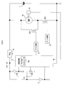
- the electric power tool 1 may use the electric motor 76 as a power source for rotating the cutter 4, and may use the one shown in FIG. 8 as a driving circuit for driving the electric motor 76.
- the drive circuit shown in FIG. 8 includes two switching elements Q51 and Q52.
- the switching element Q52 is provided in series on the energization path from the battery 7 to the electric motor 76, while the switching element Q51 is connected to the electric motor 76. It is provided in parallel.
- the drain of the switching element Q51 is connected to the positive electrode of the battery 7, and the source of the switching element Q51 is connected between the drain of the switching element Q52 and the terminal of the electric motor 76.
- the start timing of the electric motor drive process may be, for example, the timing when the control circuit 14 is started, that is, the timing when electric power is supplied to each part of the electric tool 1.
- the present invention is applied to the electric tool configured as a brush cutter.
- the present invention may be applied to other types of electric tools such as a grinder.
Landscapes
- Engineering & Computer Science (AREA)
- Power Engineering (AREA)
- Mechanical Engineering (AREA)
- Life Sciences & Earth Sciences (AREA)
- Environmental Sciences (AREA)
- Portable Power Tools In General (AREA)
- Control Of Ac Motors In General (AREA)
- Control Of Electric Motors In General (AREA)
- Stopping Of Electric Motors (AREA)
Abstract
Description
このカッターの回転を停止させるための1つの方法として、下記特許文献1では、回生制動を用いることが開示されている。回生制動では、電動機のコイルへの通電が遮断され、コイルの両端が短絡されることで、電動機の回転子に対して、大きな制動力が発生する。つまり、回生制動を用いると、回転子の回転、ひいてはカッターの回転を急激に停止させることができる。
この電動工具では、電動機が、駆動対象を回転させる駆動力を発生する一方で、回転速度検出手段が、電動機の回転速度を検出する。電機機への電流供給を遮断するための停止指令が発行されてから、回転速度検出手段で検出された回転速度が、任意に設定された規定回転速度以下となると、回転速度基準作動手段が、制動手段を作動させ、制動手段が、電動機を制動させる制動制御を実行する。
このため、この電動工具では、電動機の回転速度が、規定回転速度まで低下した後で電動機を制動するため、電動機の制動によって当該電動工具に加わる反動を低減することができる。つまり、この電動工具では、電動機の制動に起因する使用感の低下を抑制することができる。
なお、制動制御開始時間は、当該電動工具の使用状況に応じて設定されるものでもよい。この場合、本発明の電動工具は、制動制御開始時間を設定する時間設定手段を備えているとよい。
また、本発明の電動工具は、回転速度検出手段の検出結果に基づいて、電動機の回転速度が単位期間に減少する割合である減少率を順次導出する減少率導出手段を備えてもよく、この場合、時間設定手段は、減少率導出手段によって導出された減少率に基づいて、制動制御開始時間を設定するように構成されているとよい。
なお、時間設定手段は、減少率が大きいほど短い時間長を制動制御開始時間として設定することが好ましい。
この場合、時間設定手段は、オフ時回転速度が大きいほど長い時間長を制動制御開始時間として設定することが好ましい。
なお、電動工具は、オフ時回転速度を直接検出するセンサーなどを備えてもよいし、指令値取得手段によって取得された指令値に基づいて、オフ時回転速度を推定する推定手段を備えてもよい。
また、駆動対象は、複数種類の駆動対象から選択され、電動工具は、複数種類の駆動対象のうちの選択された1つを装着可能に構成されていてもよい。この場合、時間設定手段は、複数種類の駆動対象のうち、慣性が最大である駆動対象に対応する制動制御開始時間を、電動工具の制動制御開始時間として設定するように構成されているとよい。
例えば、正転方向に比べて、逆転方向の回転速度が低くなるように電動工具が構成されている場合には、逆転方向に対する制動制御開始時間は、正転方向に対する制動制御開始時間よりも短い時間長に設定されていることが好ましい。
このように構成された電動工具では、想定以上に大きな運動エネルギが、駆動力伝達機構に加わる可能性を低減できる。この結果、駆動力伝達機構への疲労の蓄積を抑制でき、駆動力伝達機構の寿命を長くすることができる。
[第1実施形態]
〈電動工具の全体構成〉
図1に示すように、電動工具1は、草や小径木を刈り払う、所謂、刈払機として構成され、シャフトパイプ2と、モータユニット3と、カッター4とを備えている。
バッテリ7は、充電可能な二次電池(例えばリチウムイオン二次電池)を当該バッテリ7の内部に備えている。このバッテリ7は、モータユニット3に対して着脱可能に構成されている。
また、シャフトパイプ2の内部には、駆動力伝達軸(以下、伝達軸と略称する)21が収容されている。伝達軸21は、当該伝達軸21の上端側において、電動機18の駆動軸に連結され、当該伝達軸21の下端側において、複数のギアを含むギア部6を介してカッター4に連結されている。
〈電動工具の電気的構成〉
図2に示すように、電動工具1は、上述の電動機18と、ブリッジ回路20と、6基のゲート回路31~36と、制御回路14とを備えている。
ブリッジ回路20は、6つのスイッチング素子Q1~Q6を備える周知の三相ブリッジ回路である。このブリッジ回路20では、直列接続されたスイッチング素子Q1,Q4の一組と、直列接続されたスイッチング素子Q2,Q5の一組と、直列接続されたスイッチング素子Q3,Q6の一組とがバッテリ7の正極と負極との間で互いに並列接続されている。そして、スイッチング素子Q1,Q4の間と、スイッチング素子Q2,Q5の間と、スイッチング素子Q3,Q6の間とにそれぞれ、電動機18の各相U,V,Wのコイルが接続されている。
制御回路14には、定電圧電源回路(Reg)15が接続されており、制御回路14は、Reg15にて、バッテリ7の直流電圧(例えば36VDC)を降圧して生成された所定の制御電圧Vcc(例えば5VDC)によって動作するように設定されている。
ロックオフスイッチ11は、電動工具1の使用者が、電動機18を誤って駆動させてしまうのを防止するためのスイッチである。より具体的には、ロックオフスイッチ11がオフされると、ロックオフスイッチ11から制御回路14に入力される信号(駆動禁止信号)の電圧の論理レベルがローレベルに設定される(つまり、電動機18の駆動は禁止される)一方、ロックオフスイッチ11がオンされると、駆動禁止信号の電圧の論理レベルがハイレベルに設定される(電動機18の駆動は許可される)。
つまり、制御回路14は、ロックオフスイッチ11及びトリガスイッチ12が共にオンされているときに、トリガスイッチ12からの速度指令値Cvに応じた回転速度で電動機18の回転子を回動させるように、駆動信号を各ゲート回路31~36へ出力する。
〈制御回路における処理〉
以下、制御回路14(より正確にはマイクロコンピュータ14A)が実行する処理について説明する。
トリガスイッチ検出処理では、トリガスイッチ12から入力される速度指令値Cvを検出する。より具体的には、使用者がトリガスイッチ12を操作する操作量により可変抵抗器12Bの抵抗値が変化し、その抵抗値に応じた電圧を速度指令値Cvとして検出する。
そして、S180では、S170にて取得された回転速度Nが、S150またはS160のいずれかにて取得された規定回転速度ThN以下であるか否かを判定する。その判定の結果、回転速度Nが規定回転速度ThN以下であれば(S180:YES)、S190へと進む。
[第1実施形態の効果]
以上説明したように、本第1実施形態の電動機駆動処理において、制動処理は、電動機18の各相U,V,Wのコイルへの電流供給が停止された後、回転速度Nが規定回転速度ThN以下となると実行される。
[第2実施形態]
次に、本発明の第2実施形態について説明する。
このため、本第2実施形態では、上記第1実施形態に記載の電動工具1とは異なる電動機駆動処理を中心に説明し、上記第1実施形態の電動工具1と同様の構成については、同一の符号を付して説明を省略する。
〈電動機駆動処理〉
図5に示すように、本第2実施形態の電動機駆動処理は、まず、速度指令値Cvが規定値Thv未満であるか否かを判定する(S310)。
一方、S340での判定の結果、正逆切替スイッチ13からの正転信号がローレベルであれば(S340:NO)、電動機18の回転子の回転方向が逆転方向であるものと判定して、S360へと進み、逆転方向の制動開始時間BTを取得する。
[第2実施形態の効果]
以上説明したように、本第2実施形態の電動機駆動処理において、制動処理は、トリガスイッチ12がオフされてから、制動開始時間BTが経過すると実行される。
ところで、本第2実施形態の電動工具は、正転方向に比べて、逆転方向の回転速度が低くなるように構成されている。このため、回転子を逆転方向に最高速で回転させたとしても、回転子を正転方向に最高速で回転させた場合よりも、回転中のカッターが有する運動エネルギは小さい。しかも、本第2実施形態では、逆転方向に対する制動開始時間BTが、正転方向に対する制動開始時間BTよりも、短い時間長に規定されている。
なお、逆転方向に対する制動開始時間BTは、正転方向に対する制動開始時間BTと同じであっても異なっていても良い。
[第3実施形態]
次に、本発明の第3実施形態について説明する。
このため、本第3実施形態においては、上記第1,第2実施形態に記載の電動工具1とは異なる電動機駆動処理を中心に説明し、上記第1,第2実施形態に記載の電動工具1と同様の構成については、同一の符号を付して説明を省略する。
〈電動機駆動処理〉
図6A-6Bに示すように、本第3実施形態の電動機駆動処理では、まず、速度指令値Cvが規定値Thv未満であるか否かを判定する(S510)。そのS510での判定の結果、速度指令値Cvが規定値Thv以上であれば(S510:NO)、S520へと進む。すなわち、ロックオフスイッチ11とトリガスイッチ12とが共にオンされているとみなすことができる場合に、S520へと進む。
続くS560では、S510にて最初に速度指令値Cvが規定値Thv未満であると判定されてから、予め規定された時間長(例えば、数十[ms])である第1設定時間が経過したか否かを判定する。そのS560での判定の結果、第1設定時間が経過していなければ(S560:NO)、S570へと移行する。すなわち、S570へと移行する条件は、トリガスイッチ12がオフされた直後である場合である。
なお、S560での判定の結果、S510にて速度指令値Cvが規定値Thv未満であると判定されてから第1設定時間が経過している場合にも、S590へと進む。
続く、S610では、所定の単位期間において、第2回転速度N_oldから第1回転速度N_newに回転速度が減少する減少率を算出する。
減少率に対応する規定回転速度は、減少率と対応付けられた回転子の回転速度である。ただし、減少率に対応する回転速度は、回転中であるカッター4が有する運動エネルギが予め設定された設定値以下となる回転速度であり、減少率が大きいほど大きくなる。
そのS630では、S570で設定した制動開始時間BT1よりもS620で設定した制動開始時間BT2が小さいか否かを判定する。S630の判定の結果、制動開始時間BT1よりも制動開始時間BT2が小さければ(S630:YES)、S640に処理を移行する。S630の判定の結果、制動開始時間BT2が制動開始時間BT1以上であれば(S630:NO)、S650に移行する。なお、S620を一度も実行することなくS630に移行した場合には、制動開始時間BT2に適正な値が設定されていないので、S630では、制動開始時間BT2が制動開始時間BT1以上であると判定される。
S660では、S550にて取得された回転速度Nが、S620にて設定された規定回転速度ThN以下であるか否かを判定する。その判定の結果、回転速度Nが規定回転速度ThNよりも大きければ(S660:NO)、S670へと進む。ただし、S620を一度も実行することなくS660へと移行した場合には、S660では回転速度Nが規定回転速度ThNよりも大きいと判定される。
[第3実施形態の効果]
以上説明したように、本第3実施形態の電動機駆動処理において、制動処理は、トリガスイッチ12がオフされてから、制動開始時間BTが経過した場合、もしくは回転速度Nが規定回転速度ThN以下となった場合に実行される。
特に、本第3実施形態の電動機駆動処理では、制動開始時間BTの設定がトリガスイッチ12がオフされた直後から実行される。このため、本第3実施形態の電動工具によれば、制動開始時間BTを、電動機18の回転子の回転を停止させようとした際の電動工具の使用状況に応じて規定することができる。
[第4実施形態]
次に、本発明の第4実施形態について説明する。
このため、本第4実施形態においては、第1~第3実施形態の電動工具1とは異なる電動機、及びその電動機を駆動するための電気的構成を中心に説明し、第1~第3実施形態の電動工具1と同様の構成及び処理については、同一の符号を付して説明を省略する。
〈電動工具の電気的構成〉
ここで、図7は、本第4実施形態における電動工具の電気的構成を示したブロック図である。
なお、電動機76の駆動軸には、駆動軸の回転角度を検出するための位置検出部75が設けられている。この位置検出部75は、周知のエンコーダ(いわゆるロータリエンコーダ)を備え、エンコーダからの検出信号を制御回路14に出力する。
〈制動処理〉
本第4実施形態における制動処理では、ハイサイドスイッチとして機能するスイッチング素子Q41,Q42の群、またはローサイドスイッチとして機能するスイッチング素子Q43,Q44の群のうち、何れか一方の群のみをオンするように、ゲート回路31~34に駆動信号を出力する。このような制動処理により、電動機76のコイルの両端が短絡する。これにより、いわゆる回生制動が発生し、慣性によって回転中であった電動機76の回転子に制動力が加えられる。
[第4実施形態の効果]
以上説明したように、本第4実施形態の電動工具70においては、カッター4を回転させるための動力源として、ブラシ付きDCモータを用い、そのブラシ付きDCモータを駆動するための駆動回路として、Hブリッジ回路を用いた。
[その他の実施形態]
以上、本発明の実施形態について説明したが、本発明は上記第1~第4実施形態に限定されるものではなく、本発明の要旨を逸脱しない範囲において、様々な態様にて実施することが可能である。
しかし、スイッチング素子Q52がオフされ、スイッチング素子Q51のみがオンされると、バッテリ7から電動機76のコイルへの電流供給が遮断されると共に、コイルの両端が短絡される。これにより、いわゆる回生制動が発生し、慣性によって回転中であった電動機76の回転子に制動力が加えられる。
Claims (16)
- 駆動対象を回転させる駆動力を発生する電動機と、
前記電動機の回転速度を検出する回転速度検出手段と、
前記電動機を制動させる制動制御を実行する制動手段と、
前記電動機への電流供給を遮断するための停止指令が発行されてから、前記回転速度検出手段で検出された回転速度が、任意に設定された規定回転速度以下となると、前記制動手段を作動させる回転速度基準作動手段と
を備えることを特徴とする電動工具。 - 前記停止指令が発行されてから、任意に設定された時間長である制動制御開始時間が経過すると、前記制動手段を作動させる時間基準作動手段を備える
ことを特徴とする請求項1に記載の電動工具。 - 前記規定回転速度を設定する規定速度設定手段を備える
ことを特徴とする請求項1または請求項2に記載の電動工具。 - 前記回転速度検出手段の検出結果に基づいて、前記電動機の回転速度が単位期間に減少する割合である減少率を順次導出する減少率導出手段を備え、
前記規定速度設定手段は、
前記減少率導出手段によって導出された前記減少率に基づいて、前記規定回転速度を設定する
ことを特徴とする請求項3に記載の電動工具。 - 前記規定速度設定手段は、
前記減少率が大きいほど大きな値を前記規定回転速度として設定する
ことを特徴とする請求項4に記載の電動工具。 - 前記電動機は、正転方向及び逆転方向に回転可能に構成されており、
前記規定速度設定手段は、
前記正転方向、前記逆転方向それぞれに対して、個別の前記規定回転速度を設定する
ことを特徴とする請求項3から請求項5の何れか一項に記載の電動工具。 - 前記制動制御開始時間を設定する時間設定手段を備える
ことを特徴とする請求項2に記載の電動工具。 - 前記回転速度検出手段の検出結果に基づいて、前記電動機の回転速度が単位期間に減少する割合である減少率を順次導出する減少率導出手段を備え、
前記時間設定手段は、
前記減少率導出手段によって導出された減少率に基づいて、前記制動制御開始時間を設定する
ことを特徴とする請求項7に記載の電動工具。 - 前記時間設定手段は、
前記減少率が大きいほど短い時間長を前記制動制御開始時間として設定する
ことを特徴とする請求項8に記載の電動工具。 - 前記電動機の回転速度の指令値を設定するための回転速度指令スイッチと、
前記回転速度指令スイッチによって設定された前記指令値を取得する指令値取得手段と
を備え、
前記時間設定手段は、
前記指令値取得手段によって取得された前記指令値が、前記電動機の停止が指令されたとみなされる停止範囲内となった際の回転速度であるオフ時回転速度に基づいて、前記制動制御開始時間を設定する
ことを特徴とする請求項7から請求項9の何れか一項に記載の電動工具。 - 前記時間設定手段は、
前記オフ時回転速度が大きいほど長い時間長を前記制動制御開始時間として設定することを特徴とする請求項10に記載の電動工具。 - 前記時間設定手段は、
前記指令値取得手段によって取得された前記指令値に基づいて、前記オフ時回転速度を推定する推定手段
を備えることを特徴とする請求項10または請求項11に記載の電動工具。 - 前記推定手段は、
前記指令値が前記停止範囲内となる規定時間前の前記指令値の値が大きいほど大きな値として、前記オフ時回転速度を推定することを特徴とする請求項12に記載の電動工具。 - 前記駆動対象は、複数種類の駆動対象から選択され、
当該電動工具は、前記複数種類の駆動対象のうちの選択された1つを装着可能に構成されており、
前記時間設定手段は、
前記複数種類の駆動対象のうち、慣性が最大である駆動対象に対応する制動制御開始時間を、当該電動工具の前記制動制御開始時間として設定する
ことを特徴とする請求項7から請求項13の何れか一項に記載の電動工具。 - 前記電動機は、正転方向及び逆転方向に回転可能に構成されており、
前記時間設定手段は、
前記正転、前記逆転それぞれに対して、個別の前記制動制御開始時間を設定することを特徴とする請求項7から請求項14の何れか一項に記載の電動工具。 - 前記駆動対象に前記電動機の駆動力を伝達する駆動力伝達機構を備える
ことを特徴とする請求項1から請求項15の何れか一項に記載の電動工具。
Priority Applications (4)
| Application Number | Priority Date | Filing Date | Title |
|---|---|---|---|
| RU2012132180/02A RU2555315C2 (ru) | 2009-12-28 | 2010-12-20 | Электрифицированный инструмент |
| US13/519,041 US20120279743A1 (en) | 2009-12-28 | 2010-12-20 | Electric power tool |
| CN201080059861.7A CN102712083B (zh) | 2009-12-28 | 2010-12-20 | 电动工具 |
| EP10840907.9A EP2520397B1 (en) | 2009-12-28 | 2010-12-20 | Motorized tool |
Applications Claiming Priority (2)
| Application Number | Priority Date | Filing Date | Title |
|---|---|---|---|
| JP2009298292A JP5351752B2 (ja) | 2009-12-28 | 2009-12-28 | 電動工具 |
| JP2009-298292 | 2009-12-28 |
Publications (1)
| Publication Number | Publication Date |
|---|---|
| WO2011081050A1 true WO2011081050A1 (ja) | 2011-07-07 |
Family
ID=44226458
Family Applications (1)
| Application Number | Title | Priority Date | Filing Date |
|---|---|---|---|
| PCT/JP2010/072917 Ceased WO2011081050A1 (ja) | 2009-12-28 | 2010-12-20 | 電動工具 |
Country Status (6)
| Country | Link |
|---|---|
| US (1) | US20120279743A1 (ja) |
| EP (1) | EP2520397B1 (ja) |
| JP (1) | JP5351752B2 (ja) |
| CN (1) | CN102712083B (ja) |
| RU (1) | RU2555315C2 (ja) |
| WO (1) | WO2011081050A1 (ja) |
Families Citing this family (36)
| Publication number | Priority date | Publication date | Assignee | Title |
|---|---|---|---|---|
| JP5203243B2 (ja) * | 2009-02-03 | 2013-06-05 | 株式会社マキタ | ネジ締め付け工具 |
| JP5256151B2 (ja) * | 2009-09-02 | 2013-08-07 | 株式会社マキタ | 刈払機 |
| EP2433757B1 (en) * | 2010-09-28 | 2014-12-31 | Black & Decker Inc. | Power tool and method of controlling a motor inside a power tool |
| DE102012215457A1 (de) * | 2012-08-31 | 2014-03-06 | Robert Bosch Gmbh | Werkzeugmaschine |
| JP5995785B2 (ja) * | 2013-05-31 | 2016-09-21 | 株式会社マキタ | 刈払機 |
| CN104579054A (zh) * | 2013-10-24 | 2015-04-29 | 创科户外产品技术有限公司 | 用于电动工具的电机控制系统 |
| EP2875904B1 (en) * | 2013-11-21 | 2016-10-05 | Robert Bosch Gmbh | Switching device for electrically driveable garden tools |
| JP6159666B2 (ja) * | 2014-02-05 | 2017-07-05 | 株式会社マキタ | 電動機械器具 |
| US9742342B2 (en) * | 2014-07-23 | 2017-08-22 | Jelley Technology Co., Ltd. | Motor driving apparatus |
| JP6457798B2 (ja) * | 2014-11-26 | 2019-01-23 | 株式会社マキタ | 電動機器 |
| WO2016084553A1 (ja) * | 2014-11-28 | 2016-06-02 | 日立工機株式会社 | 電動工具 |
| JP6460354B2 (ja) * | 2014-12-18 | 2019-01-30 | 工機ホールディングス株式会社 | 電動工具 |
| CN105983945B (zh) * | 2015-01-28 | 2018-09-07 | 苏州宝时得电动工具有限公司 | 动力工具及用于动力工具的控制方法 |
| JP2017087359A (ja) * | 2015-11-11 | 2017-05-25 | 株式会社マキタ | 電動作業機および作業機管理システム |
| EP3398724B1 (en) * | 2015-12-28 | 2023-01-04 | Koki Holdings Co., Ltd. | Electric tool |
| JP2017225213A (ja) | 2016-06-13 | 2017-12-21 | 本田技研工業株式会社 | 電動芝刈り機の制御装置 |
| JP6778575B2 (ja) * | 2016-10-05 | 2020-11-04 | 株式会社マキタ | 作業機 |
| JP6767836B2 (ja) * | 2016-10-05 | 2020-10-14 | 株式会社マキタ | 作業機 |
| US10090784B2 (en) * | 2017-01-19 | 2018-10-02 | X'pole Precision Tools Inc. | Electric hand tool and electromagnetic brake control method thereof |
| EP3351348B1 (en) * | 2017-01-24 | 2022-05-11 | X'Pole Precision Tools Inc. | Electric hand tool and electromagnetic brake control method thereof |
| JP2019051579A (ja) * | 2017-09-19 | 2019-04-04 | 株式会社マキタ | 電動作業機 |
| CN108925210A (zh) * | 2018-08-31 | 2018-12-04 | 浙江天泰机械有限公司 | 草坪机控制方法和装置 |
| CN110622679B (zh) * | 2019-10-15 | 2022-04-22 | 广西润源园林建设有限公司 | 一种园林机械的防缠草装置 |
| EP3892082B1 (de) * | 2020-04-09 | 2024-12-25 | Andreas Stihl AG & Co. KG | Handgriff für ein handgeführtes arbeitsgerät und freischneider |
| US11557989B2 (en) | 2020-06-11 | 2023-01-17 | Milwaukee Electric Tool Corporation | Voltage-based braking methodology for a power tool |
| DE102020121317A1 (de) | 2020-08-13 | 2022-02-17 | Marquardt Gmbh | Steuereinheit zum Steuern eines Motors |
| CN116390833A (zh) | 2020-10-19 | 2023-07-04 | 胡斯华纳有限公司 | 具有反冲减轻功能的手持式电动切断工具 |
| CN114584004B (zh) * | 2020-12-01 | 2026-03-20 | 南京泉峰科技有限公司 | 智能电动工具及其控制方法 |
| US12439846B2 (en) | 2021-04-19 | 2025-10-14 | Milwaukee Electric Tool Corporation | String trimmer head |
| WO2023278747A1 (en) | 2021-06-30 | 2023-01-05 | Milwaukee Electric Tool Corporation | String trimmer assembly and trimmer head for use with same |
| US12582029B2 (en) | 2021-06-30 | 2026-03-24 | Milwaukee Electric Tool Corporation | String trimmer head |
| USD1105868S1 (en) * | 2023-02-06 | 2025-12-16 | Husqvarna Ab | Grass trimmer |
| USD1105869S1 (en) * | 2023-02-06 | 2025-12-16 | Husqvarna Ab | Grass trimmer |
| USD1074340S1 (en) * | 2023-02-20 | 2025-05-13 | Zhejiang Guyuehu Industry and Trade Co., Ltd. | Grass trimmer |
| USD1074341S1 (en) * | 2023-02-20 | 2025-05-13 | Zhejiang Guyuehu Industry and Trade Co., Ltd. | Grass trimmer |
| USD1111724S1 (en) * | 2023-08-25 | 2026-02-10 | Husqvarna Ab | Grass trimmer |
Citations (3)
| Publication number | Priority date | Publication date | Assignee | Title |
|---|---|---|---|---|
| JPH07148676A (ja) * | 1993-11-25 | 1995-06-13 | Matsushita Electric Works Ltd | 電動工具の発電制動回路 |
| JPH0866074A (ja) | 1994-08-19 | 1996-03-08 | Kokusan Denki Co Ltd | 電動機の停止制御方法及び装置 |
| JP2005176454A (ja) * | 2003-12-09 | 2005-06-30 | Matsushita Electric Works Ltd | モータ制御装置およびそれを用いた電動工具 |
Family Cites Families (17)
| Publication number | Priority date | Publication date | Assignee | Title |
|---|---|---|---|---|
| SU612783A1 (ru) * | 1975-08-25 | 1978-06-30 | Предприятие П/Я М-5147 | Предельный электромеханический гайковерт |
| US4267914A (en) * | 1979-04-26 | 1981-05-19 | Black & Decker Inc. | Anti-kickback power tool control |
| US4804893A (en) * | 1987-05-11 | 1989-02-14 | Caterpillar Industrial Inc. | Electric braking control |
| SU1565669A2 (ru) * | 1988-05-04 | 1990-05-23 | Специализированное Конструкторское Бюро По Механизации И Автоматизации Слесарно-Сборочных Работ "Мехинструмент" | Электромеханический гайковерт |
| IT1258950B (it) * | 1992-06-05 | 1996-03-11 | Black & Decker Inc | Dispositivo di frenatura controllata per motori elettrici, in particolare di utensili portatili |
| JPH0723577A (ja) * | 1993-01-27 | 1995-01-24 | Nec Corp | モータ制御回路 |
| JPH0822328A (ja) * | 1994-07-07 | 1996-01-23 | Minolta Co Ltd | 駆動モータ制御装置 |
| US6609900B2 (en) * | 1996-09-30 | 2003-08-26 | Terumo Cardiovascular Systems Corporation | Dynamic brake with backlash control for peristaltic pump |
| US6037729A (en) * | 1997-02-06 | 2000-03-14 | Black & Decker Inc. | Apparatus and method for braking electric motors |
| US6025683A (en) * | 1998-12-23 | 2000-02-15 | Stryker Corporation | Motor control circuit for regulating a D.C. motor |
| DE10117121A1 (de) * | 2001-04-06 | 2002-10-17 | Bosch Gmbh Robert | Handwerkzeugmaschine |
| US6831432B2 (en) * | 2001-12-05 | 2004-12-14 | Matsushita Electric Industrial Co., Ltd. | Motor driving device and motor driving method |
| TWI274468B (en) * | 2005-05-04 | 2007-02-21 | Sunplus Technology Co Ltd | Brake system and method for a direct current brushed motor without a hall sensor |
| JP4053557B2 (ja) * | 2005-10-07 | 2008-02-27 | ファナック株式会社 | サーボモータ停止制御方法及びサーボモータ制御装置 |
| CN101300110B (zh) * | 2005-11-04 | 2013-05-29 | 罗伯特·博世有限公司 | 具有集成电路板的铰接钻和操作方法 |
| JP4609489B2 (ja) * | 2007-12-25 | 2011-01-12 | パナソニック電工株式会社 | 電動工具 |
| RU2381098C2 (ru) * | 2008-04-21 | 2010-02-10 | ЗАКРЫТОЕ АКЦИОНЕРНОЕ ОБЩЕСТВО "ИНГЕРСОЛЛ-РЭНД СиАйЭс" | Способ затяжки резьбовых соединений и устройство для его осуществления |
-
2009
- 2009-12-28 JP JP2009298292A patent/JP5351752B2/ja active Active
-
2010
- 2010-12-20 RU RU2012132180/02A patent/RU2555315C2/ru active
- 2010-12-20 EP EP10840907.9A patent/EP2520397B1/en active Active
- 2010-12-20 WO PCT/JP2010/072917 patent/WO2011081050A1/ja not_active Ceased
- 2010-12-20 US US13/519,041 patent/US20120279743A1/en not_active Abandoned
- 2010-12-20 CN CN201080059861.7A patent/CN102712083B/zh active Active
Patent Citations (3)
| Publication number | Priority date | Publication date | Assignee | Title |
|---|---|---|---|---|
| JPH07148676A (ja) * | 1993-11-25 | 1995-06-13 | Matsushita Electric Works Ltd | 電動工具の発電制動回路 |
| JPH0866074A (ja) | 1994-08-19 | 1996-03-08 | Kokusan Denki Co Ltd | 電動機の停止制御方法及び装置 |
| JP2005176454A (ja) * | 2003-12-09 | 2005-06-30 | Matsushita Electric Works Ltd | モータ制御装置およびそれを用いた電動工具 |
Non-Patent Citations (1)
| Title |
|---|
| See also references of EP2520397A4 |
Also Published As
| Publication number | Publication date |
|---|---|
| US20120279743A1 (en) | 2012-11-08 |
| EP2520397A4 (en) | 2016-03-23 |
| CN102712083A (zh) | 2012-10-03 |
| CN102712083B (zh) | 2015-11-25 |
| EP2520397B1 (en) | 2018-08-15 |
| JP2011136399A (ja) | 2011-07-14 |
| RU2012132180A (ru) | 2014-02-10 |
| RU2555315C2 (ru) | 2015-07-10 |
| JP5351752B2 (ja) | 2013-11-27 |
| EP2520397A1 (en) | 2012-11-07 |
Similar Documents
| Publication | Publication Date | Title |
|---|---|---|
| JP5351752B2 (ja) | 電動工具 | |
| JP5360344B2 (ja) | 電動工具 | |
| JP5824419B2 (ja) | 電動工具 | |
| US11533841B2 (en) | Electric working machine and method for controlling motor of electric working machine | |
| JP5469000B2 (ja) | 電動工具、ロック状態発生判定装置、及びプログラム | |
| JP6767836B2 (ja) | 作業機 | |
| JP6297854B2 (ja) | 回転打撃工具 | |
| JP5792123B2 (ja) | 回転打撃工具 | |
| JP6916060B2 (ja) | 電動作業機 | |
| US11641798B2 (en) | Electric working machine capable of determining type of tip tool | |
| JP2017070102A (ja) | モータの制御装置 | |
| JP2018057326A (ja) | 作業機 | |
| JP2018051678A (ja) | 電動工具 | |
| WO2013136673A1 (ja) | 電動工具 | |
| JP6675259B2 (ja) | 電動作業機 | |
| JP2017205834A (ja) | 電動作業機 | |
| EP2818281B1 (en) | Electric power tool | |
| JP6095526B2 (ja) | 回転打撃工具 | |
| TWI819434B (zh) | 電動工具及其制動方法 | |
| JP6028075B2 (ja) | 回転打撃工具 | |
| US12508693B2 (en) | Technique for controlling motor in electric power tool | |
| JP2025163936A (ja) | 電動作業機 |
Legal Events
| Date | Code | Title | Description |
|---|---|---|---|
| WWE | Wipo information: entry into national phase |
Ref document number: 201080059861.7 Country of ref document: CN |
|
| 121 | Ep: the epo has been informed by wipo that ep was designated in this application |
Ref document number: 10840907 Country of ref document: EP Kind code of ref document: A1 |
|
| WWE | Wipo information: entry into national phase |
Ref document number: 13519041 Country of ref document: US |
|
| NENP | Non-entry into the national phase |
Ref country code: DE |
|
| WWE | Wipo information: entry into national phase |
Ref document number: 2010840907 Country of ref document: EP |
|
| WWE | Wipo information: entry into national phase |
Ref document number: 2012132180 Country of ref document: RU |