WO2011082646A1 - 一种反馈多载波信道信息的方法及装置 - Google Patents
一种反馈多载波信道信息的方法及装置 Download PDFInfo
- Publication number
- WO2011082646A1 WO2011082646A1 PCT/CN2010/080575 CN2010080575W WO2011082646A1 WO 2011082646 A1 WO2011082646 A1 WO 2011082646A1 CN 2010080575 W CN2010080575 W CN 2010080575W WO 2011082646 A1 WO2011082646 A1 WO 2011082646A1
- Authority
- WO
- WIPO (PCT)
- Prior art keywords
- information
- downlink
- carrier
- channel
- cqi
- Prior art date
- Legal status (The legal status is an assumption and is not a legal conclusion. Google has not performed a legal analysis and makes no representation as to the accuracy of the status listed.)
- Ceased
Links
Classifications
-
- H—ELECTRICITY
- H04—ELECTRIC COMMUNICATION TECHNIQUE
- H04L—TRANSMISSION OF DIGITAL INFORMATION, e.g. TELEGRAPHIC COMMUNICATION
- H04L1/00—Arrangements for detecting or preventing errors in the information received
- H04L1/0001—Systems modifying transmission characteristics according to link quality, e.g. power backoff
- H04L1/0023—Systems modifying transmission characteristics according to link quality, e.g. power backoff characterised by the signalling
- H04L1/0026—Transmission of channel quality indication
-
- H—ELECTRICITY
- H04—ELECTRIC COMMUNICATION TECHNIQUE
- H04L—TRANSMISSION OF DIGITAL INFORMATION, e.g. TELEGRAPHIC COMMUNICATION
- H04L1/00—Arrangements for detecting or preventing errors in the information received
- H04L1/0001—Systems modifying transmission characteristics according to link quality, e.g. power backoff
- H04L1/0023—Systems modifying transmission characteristics according to link quality, e.g. power backoff characterised by the signalling
- H04L1/0028—Formatting
- H04L1/0029—Reduction of the amount of signalling, e.g. retention of useful signalling or differential signalling
-
- H—ELECTRICITY
- H04—ELECTRIC COMMUNICATION TECHNIQUE
- H04L—TRANSMISSION OF DIGITAL INFORMATION, e.g. TELEGRAPHIC COMMUNICATION
- H04L1/00—Arrangements for detecting or preventing errors in the information received
- H04L1/0001—Systems modifying transmission characteristics according to link quality, e.g. power backoff
- H04L1/0023—Systems modifying transmission characteristics according to link quality, e.g. power backoff characterised by the signalling
- H04L1/0028—Formatting
- H04L1/003—Adaptive formatting arrangements particular to signalling, e.g. variable amount of bits
-
- H—ELECTRICITY
- H04—ELECTRIC COMMUNICATION TECHNIQUE
- H04L—TRANSMISSION OF DIGITAL INFORMATION, e.g. TELEGRAPHIC COMMUNICATION
- H04L1/00—Arrangements for detecting or preventing errors in the information received
- H04L1/0001—Systems modifying transmission characteristics according to link quality, e.g. power backoff
- H04L1/0023—Systems modifying transmission characteristics according to link quality, e.g. power backoff characterised by the signalling
- H04L1/0028—Formatting
- H04L1/0031—Multiple signaling transmission
-
- H—ELECTRICITY
- H04—ELECTRIC COMMUNICATION TECHNIQUE
- H04L—TRANSMISSION OF DIGITAL INFORMATION, e.g. TELEGRAPHIC COMMUNICATION
- H04L5/00—Arrangements affording multiple use of the transmission path
- H04L5/003—Arrangements for allocating sub-channels of the transmission path
- H04L5/0053—Allocation of signalling, i.e. of overhead other than pilot signals
-
- H—ELECTRICITY
- H04—ELECTRIC COMMUNICATION TECHNIQUE
- H04L—TRANSMISSION OF DIGITAL INFORMATION, e.g. TELEGRAPHIC COMMUNICATION
- H04L1/00—Arrangements for detecting or preventing errors in the information received
- H04L1/004—Arrangements for detecting or preventing errors in the information received by using forward error control
- H04L1/0056—Systems characterized by the type of code used
- H04L1/0067—Rate matching
-
- H—ELECTRICITY
- H04—ELECTRIC COMMUNICATION TECHNIQUE
- H04L—TRANSMISSION OF DIGITAL INFORMATION, e.g. TELEGRAPHIC COMMUNICATION
- H04L1/00—Arrangements for detecting or preventing errors in the information received
- H04L1/004—Arrangements for detecting or preventing errors in the information received by using forward error control
- H04L1/0056—Systems characterized by the type of code used
- H04L1/0071—Use of interleaving
-
- H—ELECTRICITY
- H04—ELECTRIC COMMUNICATION TECHNIQUE
- H04L—TRANSMISSION OF DIGITAL INFORMATION, e.g. TELEGRAPHIC COMMUNICATION
- H04L1/00—Arrangements for detecting or preventing errors in the information received
- H04L1/004—Arrangements for detecting or preventing errors in the information received by using forward error control
- H04L1/0072—Error control for data other than payload data, e.g. control data
-
- H—ELECTRICITY
- H04—ELECTRIC COMMUNICATION TECHNIQUE
- H04L—TRANSMISSION OF DIGITAL INFORMATION, e.g. TELEGRAPHIC COMMUNICATION
- H04L1/00—Arrangements for detecting or preventing errors in the information received
- H04L1/12—Arrangements for detecting or preventing errors in the information received by using return channel
- H04L1/16—Arrangements for detecting or preventing errors in the information received by using return channel in which the return channel carries supervisory signals, e.g. repetition request signals
- H04L1/1607—Details of the supervisory signal
- H04L1/1664—Details of the supervisory signal the supervisory signal being transmitted together with payload signals; piggybacking
-
- H—ELECTRICITY
- H04—ELECTRIC COMMUNICATION TECHNIQUE
- H04L—TRANSMISSION OF DIGITAL INFORMATION, e.g. TELEGRAPHIC COMMUNICATION
- H04L1/00—Arrangements for detecting or preventing errors in the information received
- H04L1/12—Arrangements for detecting or preventing errors in the information received by using return channel
- H04L1/16—Arrangements for detecting or preventing errors in the information received by using return channel in which the return channel carries supervisory signals, e.g. repetition request signals
- H04L1/1607—Details of the supervisory signal
- H04L1/1671—Details of the supervisory signal the supervisory signal being transmitted together with control information
-
- H—ELECTRICITY
- H04—ELECTRIC COMMUNICATION TECHNIQUE
- H04W—WIRELESS COMMUNICATION NETWORKS
- H04W24/00—Supervisory, monitoring or testing arrangements
- H04W24/10—Scheduling measurement reports ; Arrangements for measurement reports
Definitions
- the present invention relates to the field of communication technologies, and in particular to a method and apparatus for feeding back multi-carrier channel information. Background technique
- the system only supports the transmission of a single carrier. Therefore, the UE (User Equipment) also measures the channel quality of a single downlink carrier and feeds back the measurement results, including RI ( Rank Indication). Information, CQI (Channel Quality Indicator) information, PMI (Precoding Matrix Indication) information, etc.
- the specific feedback may be periodically fed back using a PUCCH (Physical Up Control Channel) or a non-periodic feedback using a PUSCH (Physical Down Shared Channel).
- PUCCH Physical Up Control Channel
- PUSCH Physical Down Shared Channel
- the optional feedback mode in each transmission mode is limited, as specified below, where Which feedback mode the UE specifically uses in a certain transmission mode is configured by the base station through higher layer signaling.
- Transmission mode 1 Feedback mode 2-0, 3-0
- Transmission mode 2 Feedback mode 2-0, 3-0
- Transmission mode 3 Feedback mode 2-0, 3-0
- Transmission mode 4 Feedback mode 1-2, 2-2
- Transmission mode 5 Feedback mode 3-1
- Transmission mode 6 Feedback mode 1-2, 2-2
- Transmission mode 7 Feedback mode 2-0, 3-0
- the seven transmission modes are:
- Transmission mode 1 Single antenna port, using port 0
- Transmission mode 2 transmit diversity
- Transmission mode 3 Open loop spatial multiplexing
- Transmission mode 5 MU-MIMO
- Transmission mode 6 Closed-loop spatial multiplexing (RANK-1)
- Transmission mode 7 Single antenna port, using port 5
- the RI only feeds back in transmission modes 3 and 4.
- the RI is lbits information
- the rank indication (RI) is 2 bits of information.
- the bit length of the CQI/PMI fed back by the UE in the PUSCH is related to the specific feedback mode and the number of subbands defined in the system.
- the UE first interprets the RI information in the PUSCH, and interprets the CQI according to the corresponding format according to the number of layers of the RANK.
- PMI information
- the feedback mode 1-2 is a "wideband CQI+multiple mode, including wideband CQI information of 1-2 spatial codewords (4 bits per codeword) and N subband PMI information, where N is the number of subbands in the system.
- Table 2 Rank » 1 Rank - 2 Rank « l Rank > 1
- the feedback mode 2-0 is "the UE selects the sub-band innocent mode, including wideband CQI information (4 bits) of one codeword and one differential CQI information (2 bits) reflecting M UE selection subbands, where L is from N sub-subscores
- the sub-band number indication information of the M sub-bands is selected in the band, and the values of N and M are both standard specifications and system bandwidth, as shown in Table 3:
- Feedback mode 2-2 is "the method of UE selecting subband + multi-band, which includes the wideband CQI information of 1-2 spatial codewords (each 4 bits) and the difference of UE selection subbands of 1-2 spatial codewords.
- CQI information (each 2bits) and a sub-band PMI+ - broadband PMI information, as shown in Table 4:
- Feedback mode 3-0 is a "high-level configuration subband with no ⁇ , including a wideband CQI information (4bits) and N differential subband CQI information (2bits each), as shown in Table 5:
- Feedback 3-1 is the "high-level configuration subband + single ⁇ mode, including 1-2 spatial codewords of wideband CQI information (each 4bits) and 1-2 spatial codewords of N subband differential CQI information (per 2 bits) and a PMI message, as shown in Table 6:
- the RI information is separately encoded, the CQI + PMI information is separately encoded, and the ACK or NACK information is also separately encoded.
- These uplink control information are multiplexed together with the uplink data, as shown in FIG.
- the mapping of the uplink data symbols to the physical resources is performed, the CQI/PMI information is first mapped, and the uplink data is mapped to the remaining resources.
- the ACK/NACK and RI information are obtained by puncturing the uplink data.
- the four columns of symbols on both sides of the pilot are placed in the frequency domain from the low frequency to the high frequency in the first time domain and the frequency domain is placed next to the ACK/NACK.
- the column symbol first maps the RI information from the low frequency to the high frequency in the post-frequency domain, as shown in Figure lb.
- the aperiodic CQI/PMI/RI transmission in the PUSCH is triggered by the lbit CQI Request information in the DCI Format 0.
- the UE checks that the information bit 1 in the DCI format 0 is received, the relevant CQI/PMI/RI information is organized and transmitted in the PUSCH according to the foregoing pre-configured feedback mode, otherwise it is not sent.
- the definition of the feedback mode in LTE R9 is the same as that of LTE R8 and will not be described in detail here.
- LTE-Advanced LTE-Advanced
- LTE-A Long Term Evolution-Advanced
- LTE-A LTE-Advanced
- LTE-A member carrier
- FIG. 2 shows an example of discontinuous carrier aggregation.
- the research orientation of the standardization organization is that the consensus on the design of the carrier aggregation system is that the design on each carrier remains as consistent as possible with LTE Release 8, thus ensuring that the UE of R8 can work normally on each component carrier.
- the research requirements of the LTE-A system have been formulated, and the maximum support for aggregation of five member carriers is supported, and that one UE supports the maximum transmission of data on five member carriers simultaneously.
- Symmetrical and asymmetric carrier aggregation can be configured at the system angle, that is, the system supports uplink and downlink symmetric or asymmetric carrier configuration; it can also be based on UE allocation, that is, one UE is assigned to uplink and downlink symmetry or non- Symmetrical wave configuration.
- UE allocation that is, one UE is assigned to uplink and downlink symmetry or non- Symmetrical wave configuration.
- a downlink carrier can be paired with one or more upstream carriers, whereas an upstream carrier can also be paired with one or more downstream carriers.
- This pairing relationship can be systematic (that is, there is only one set of pairing relationships in the system), or it can be UE-based (that is, different users can configure different pairing relationships).
- the base station needs to obtain channel information feedback of multiple carriers measured by the UE, thereby performing multi-carrier scheduling.
- the channel information may include, for example, RI information, wideband CQI/PMI information, sub-band CQI information, and the like.
- the LTE Rel-8/9 protocol only supports channel information feedback of single carrier waves. In the case of LTE-A carrier aggregation, multi-carrier aperiodic channel information feedback has not been given. Summary of the invention
- the invention provides a method and a device for feeding back multi-carrier channel information, which are used to realize multi-carrier wave Feedback of aperiodic channel information.
- the UE performs channel information measurement on multiple downlink carriers
- the UE After receiving the trigger indication of the feedback channel information sent by the base station, the UE sends the measured channel information of the corresponding downlink carrier wave to the base station according to the obtained downlink wave set that needs to be measured and fed back.
- a first receiving unit configured to receive a downlink carrier set that needs to be measured and fed back by the base station
- a second receiving unit configured to receive a trigger indication of the feedback channel information sent by the base station
- a measuring unit configured to send, by the receiving base station, a feedback channel After the triggering indication of the information, the channel measurement is performed according to the set of downlink waves that need to be measured and anti-hungry;
- a feedback unit configured to send channel information of the measured downlink carrier to the base station.
- the base station notifies the UE of the downlink bearer set that needs to be measured and fed back;
- the base station sends a message for triggering measurement of downlink channel information to the UE, where the downlink channel information is channel information of a downlink carrier in the downlink bearer set;
- the base station receives channel information of the downlink carrier measured by the UE.
- a first sending unit configured to notify a UE of a downlink bearer set that needs to be measured and fed back
- a second sending unit configured to send, to the UE, a message for triggering measurement of downlink channel information, where the downlink channel information is The channel information of the downlink carrier in the downlink carrier set
- the receiving unit configured to receive channel information of the downlink carrier measured by the UE.
- the UE performs channel information measurement on multiple downlink carriers; after receiving the trigger indication of the feedback channel information sent by the base station, the UE determines the corresponding measurement according to the obtained downlink wave set that needs to be measured and fed back.
- the channel information of the downlink carrier wave is sent to the base station, thereby implementing feedback of the multi-carrier channel information.
- Figure lb is a schematic diagram of mapping of uplink control information in uplink physical resources in a single-carrier system
- Figure 2 is a schematic diagram of carrier wave aggregation
- FIG. 3a is a schematic diagram of uplink and downlink asymmetric aggregation and carrier pairing
- FIG. 3b is a schematic diagram of uplink and downlink symmetric aggregation and carrier pairing
- FIG. 4 is a schematic flowchart of a method performed by a base station side for implementing scheduling feedback channel information according to an embodiment of the present invention
- FIG. 5 is a schematic flowchart of a method for implementing feedback channel information according to an embodiment of the present invention
- FIG. 6 is a schematic structural diagram of an apparatus for implementing feedback channel information according to an embodiment of the present invention
- FIG. 7 is a schematic diagram of implementing feedback channel information according to an embodiment of the present invention. Schematic diagram of the device structure;
- FIG. 8a is a schematic diagram of a channel quality information and an uplink data multiplexing process of a multi-carrier according to Embodiment 1 of the present invention.
- FIG. 8b is a schematic diagram of a multi-carrier channel information feedback mapping according to Embodiment 1 of the present invention.
- 9a is a schematic diagram of a multi-carrier channel shield information and an uplink data multiplexing process according to Embodiment 2 of the present invention.
- 9b is a schematic diagram of multi-carrier channel information feedback mapping according to Embodiment 2 of the present invention.
- 10a is a schematic diagram of a multi-carrier channel shield information and uplink data multiplexing process according to Embodiment 3 of the present invention.
- FIG. 10b is a schematic diagram of multi-carrier channel information feedback mapping according to Embodiment 3 of the present invention. detailed description
- the base station in order to implement multi-carrier channel information feedback, notifies the UE of the downlink bearer set that needs to be measured and fed back in advance; the base station sends a message for triggering measurement of the downlink channel information to the UE, to trigger the UE.
- the channel of the downlink carrier is measured.
- the UE After receiving the trigger indication of the feedback channel information sent by the base station, the UE sends the channel information of the corresponding downlink carrier to the base station according to the obtained downlink wave set that needs to be measured and fed back.
- the present invention implements feedback for scheduling multi-carrier channel information, and performs execution on the base station side.
- the method includes the following steps:
- Step 401 The base station notifies the UE of the downlink bearer set that needs to be measured and fed back.
- the base station can send a downlink bearer set to the UE through high layer signaling.
- Step 402 The base station sends, to the UE, a message for triggering measurement of downlink channel information, where the downlink channel information is channel information of a downlink carrier in the downlink bearer set.
- the message for triggering measurement of the downlink channel information may be a DCI (Downlink Control Information) message, such as DCI format 0.
- DCI Downlink Control Information
- Step 403 The base station receives channel information of the downlink carrier wave measured by the UE.
- step 403 the data symbols on the extracted physical resources are deinterleaved, demultiplexed, and decoded to obtain channel information of each downlink carrier wave.
- the present invention provides feedback for scheduling multi-carrier channel information, and the method performed by the UE side includes the following steps:
- Step 501 The UE performs channel information measurement on multiple downlink carriers.
- Step 502 After receiving the trigger indication of the feedback channel information sent by the base station, the UE sends the measured channel information of the corresponding downlink carrier to the base station according to the obtained downlink wave set that needs to be measured and fed back.
- the downlink wave set that needs to be measured and fed back may be configured by the base station to the UE by using the high layer signaling, for example, the base station sends high layer signaling to the UE in advance, where the downlink wave set that needs measurement and feedback is included, and the high layer signaling is, for example, It may be RRC (Radio Resource Control) signaling.
- RRC Radio Resource Control
- the sending manner of the step 502 is: the channel information of the downlink carrier may include some types of channel feedback information, and if the trigger indication of the feedback channel information may include carrier number indication information, used to indicate each The channel information of the downlink carrier is used to feed back the uplink carrier. Therefore, the channel information of the measured downlink carrier can be sent by the UE to the base station through the corresponding uplink carrier.
- the channel information of the downlink carrier wave may include: one or more of three channel feedback information: CQI, PMI and RI.
- the other sending manner of the step 502 is: if the carrier number indication information is not clear in the triggering indication of the feedback channel information, the UE receives the pairing situation information of the downlink carrier and the uplink carrier notified by the base station, and the UE may The measured channel information of the downlink carrier wave is sent to the base station through the uplink carrier wave of the corresponding downlink carrier pair.
- the trigger indication of the feedback channel information may be DCI format 0.
- the UE may multiplex and interleave the measured channel information of the downlink carrier wave with the uplink data to be sent, and map the uplink data symbol obtained by the interleaving process to the corresponding physical resource for transmission.
- the UE multiplexes the measured channel information of the downlink carrier wave with the uplink data to be transmitted, and the interlace processing may include multiple implementation modes:
- the first type the channel coded and rate-matched service data is coded in cascade, and the CQI/PMI information of each downlink carrier is separately channel-coded; it will be separately used for channel coding;
- the processed data, the separately encoded RI information of each downlink wave, and the ACK/NACK information are separately encoded and then interleaved.
- the RI information is mapped to the Single Carrier SC-FDMA (Frequency Division Frequency Access) symbol on both sides of the DMRS (Demodulation Reference Signal) according to the rules already specified by LTE R8.
- the RI information of the carrier wave is mapped to different resource units from the low frequency to the high frequency order, and the resource unit occupied by the RI information of each carrier wave is different.
- the second mode performing code block concatenation processing on the channel coded and rate matched service data, and jointly coding the CQI/PMI information of the downlink carrier in the downlink carrier set; CQI/PMI information of the wave and the number of services after the block cascading process
- the multiplexed data, the jointly encoded downlink carrier RI information, and the separately encoded ACK/NACK information are interleaved. Therefore, when performing uplink data symbol to physical resource mapping, firstly, in the RE unit, the CQI/PMI information of each carrier wave is sequentially mapped in the first time domain and the backward frequency domain, and the CQI/PMI information of each carrier is used.
- the occupied resource units are the same, and the uplink data is mapped to the remaining physical resources, and the ACK/NACK and RI information are punctured and mapped to the physical resources, and the RI information of each carrier wave occupies the same resource unit. .
- the third type performing code block cascading processing on the channel data and the rate matched service data, and jointly coding the CQI/PMI information of the downlink carrier wave in the downlink carrier set;
- the multiplexed processed data, the separately encoded RI information of each downlink carrier, and the separately encoded ACK/NACK information are subjected to interleaving processing.
- the CQI/PMI information of each carrier wave is sequentially mapped in the first time domain and the backward frequency domain, and the CQI/PMI information of each carrier is occupied.
- the resource units are the same, and the uplink data is mapped in the remaining physical resources, and the ACK/NACK and RI information are punctured and mapped to the physical resources, and the resource units occupied by the RI information of each carrier wave are different.
- a schematic structural diagram of a device for scheduling channel information feedback includes: a first transmitting unit 61, a second transmitting unit 62, and a receiving unit 63.
- the first sending unit 61 is configured to notify the UE of the downlink bearer set that needs to be measured and fed back.
- the second sending unit 62 is configured to send, to the UE, a message for triggering measurement of downlink channel information, where the downlink channel information is Channel information of the downlink carrier in the downlink carrier set;
- the receiving unit 63 is configured to receive channel information of the downlink carrier measured by the UE.
- the first sending unit 61 is configured to send a downlink bearer set to the UE by using high layer signaling.
- the higher layer signaling may be RRC signaling.
- the message for triggering measurement of downlink channel information may be a DCI message.
- the receiving unit 63 may deinterleave, demultiplex, and decode the data symbols on the extracted physical resources to obtain channel information of each downlink carrier.
- an apparatus for feeding back multi-carrier channel information includes:
- the first receiving unit 71 is configured to receive, by the base station, a downlink wave set that needs to be measured and fed back;
- the second receiving unit 72 is configured to receive a trigger indication of the feedback channel information sent by the base station, and the measuring unit 73 is configured to perform channel information measurement on multiple downlink carriers; perform channel measurement;
- the feedback unit 74 is configured to: after receiving the trigger indication of the feedback channel information sent by the base station, send the measured channel information of the corresponding downlink carrier to the base station according to the downlink carrier set that needs to be measured and fed back.
- the first receiving unit 71 is configured to obtain a downlink wave set that needs to be measured and fed back from the high layer signaling sent by the received base station.
- the channel information of the downlink carrier wave includes a plurality of types of channel feedback information, where the triggering indication of the feedback channel information includes the carrier wave number indication information, which is used to indicate the uplink carrier occupied by the channel information feedback of each downlink carrier wave.
- the feedback unit 74 is configured to send the measured channel information of the downlink carrier to the base station by using the corresponding uplink wave.
- the channel information of the downlink carrier includes: one or more of three channel feedback information: CQI, PMI, and RI.
- the feedback unit is configured to send, according to the pairing situation information of the downlink carrier wave and the uplink carrier wave notified by the base station, the channel information of the measured downlink carrier wave to the base station by using the uplink wave of the corresponding downlink carrier pair.
- the trigger indication of the feedback channel information is DCI format 0 of the downlink control information.
- the feedback unit 74 may multiplex and interleave the measured channel information of the downlink carrier wave with the uplink data to be transmitted; and map the uplink data symbol obtained by the interleaving process to the corresponding physical resource for transmission.
- the feedback unit 74 may perform code coding and rate matching service data.
- the block is cascaded, and the CQI/PMI information of each downlink wave is separately channel-coded; the CQI/PMI information of each downlink wave that is separately channel-coded and the service data after the code block-cascade processing are performed.
- Multiplexing The multiplexed data, the separately encoded RI information of each downlink carrier, and the ACK/NACK information are separately encoded and then interleaved.
- the feedback unit 74 performs uplink data symbol to physical resource mapping, firstly, in the RE unit, the CQI/PMI information of each carrier wave is sequentially mapped in the first time domain and the backward frequency domain, and each carrier wave is used.
- the CQI/PMI information occupies different resource units, and the uplink data is mapped to the remaining physical resources, and the feedback unit 74 is configured to perform code block cascading processing on the channel data and the rate-matched service data, and
- the CQI/PMI information of the downlink carrier wave in the downlink carrier set is jointly coded; the CQI/PMI information of the jointly coded downlink carrier wave and the service data after the code block cascade processing are multiplexed; Interleaving is performed using the processed data, the RI information of the jointly encoded downlink carrier, and the separately encoded ACK/NACK information.
- the anti-debt unit 74 performs uplink data symbol-to-physical resource mapping, firstly, in the RE unit, the CQI/PMI information of each carrier wave is sequentially mapped in a first-time domain and a post-frequency domain manner, and each carrier wave is used.
- the CQI/PMI information occupies the same resource unit, and the uplink data is mapped to the remaining physical resources, and the ACK/NACK and RI information are punctured and mapped to the physical resources, and the RI information of each carrier wave is occupied.
- the resource unit is the same,
- the feedback unit 74 is configured to perform code block cascading processing on the channel coded and rate matched service data, and jointly encode the CQI/PMI information of the downlink carrier wave in the downlink carrier set;
- the CQI/PMI information of the encoded downlink carrier and the service data processed by the code block concatenation are multiplexed; the multiplexed data, the separately encoded RI information of each downlink carrier, and the separately encoded
- the ACK/NACK information is interleaved.
- the feedback unit 74 performs uplink data symbol to physical resource mapping, firstly, in the RE unit, the CQI/PMI information of each carrier wave is sequentially mapped in the first time domain and the backward frequency domain, and the CQI of each carrier is used.
- the /PMI information occupies the same resource unit, and maps the uplink data to the remaining physical resources, and punctured the uplink data to the physical data by puncturing the ACK/NACK and RI information.
- the RI information of each carrier occupies different resource units.
- the use of aperiodic CQI/PMI/RI feedback needs to support multiple carriers.
- the base station needs to configure an aperiodic feedback mode for different DL CCs (downlink member carriers).
- the feedback modes of the CCs can be the same or different.
- the specific mode is the same as that of LTE R8/9.
- the base station may use the lbit CQI Request signaling in the DCI format 0 to trigger CQI/PMI/m feedback of all CCs in the set; meanwhile, the DCI
- the CIF (Carrier Indication Field) in the format 0 is used to indicate on which UL CC the CQI/PMI/RI feedback is sent; if the CIF does not exist, the UL paired with the DL CC where the DCI Format 0 is located
- the CC sends feedback information.
- the high layer signaling may use UE-specific RRC signaling.
- the UE feeds back the CQI/PMI/RI information of the corresponding DL CC set in the UL CC (Up Link Component Carrier) configured by the high layer according to the trigger of the DCI format 0.
- the CQI request signaling in the DCI Format 0 is extended to multiple bits, and is used to indicate which DL CC CQI/PMI/RI information needs to be included in a non-periodic feedback.
- LTE-A supports up to 5 DL CC aggregations, and then 5 bits are used.
- the CQI request information uses a bitmap bitmap method to indicate which DL CC channel information is included in a non-periodic feedback. That is, the downlink wave set that needs to be measured and fed back is indicated by a bitmap bitmap mode on a plurality of bits extended in the channel quality indicator CQI request signaling of the DCI format 0.
- the base station schedules the UE to feed back channel information of all the DL CCs matched with it in a UL CC when performing aperiodic channel information feedback.
- the UE After the UE determines the DL CC set that needs to be fed back, the UE needs to multiplex the feedback information with the uplink data.
- the specific method is based on the LTE R8 based on the expansion of multi-carrier.
- the channel data and the rate-matched service data are subjected to code block concatenation processing, and the CQI/PMI information of each downlink carrier is separately channel-coded;
- the CQI/PMI information of the row wave and the service data processed by the code block cascade are multiplexed; the multiplexed data, the separately encoded RI information of each downlink wave, and the ACK7NACK information are separately encoded. Interleave processing.
- the CQI/PMI information of each DL CC in the DL CC set is separately coded, and the specific coding mode is the same as that of the LTE R8/R9, and then the multiplexing operation is unified with the uplink data.
- the multiplexing guarantees the CQI/PMI information before the uplink data, and the CQI/PMI information of different DL CCs are sequentially mapped (first time domain and then the frequency domain), and the data and control multiplexed data sequence and the RI information of each DL CC enter.
- the channel interleaver, the output of the interleaver ensures that the RI is still located at the same symbol position as LTE R8, and the resource unit occupied by the RI information of each carrier is different, and the CQI/PMI information of each carrier occupies different resource units. .
- RI information of different carriers is mapped from different low-frequency to high-frequency sequences in different resource units.
- the CQI/PMI information of each carrier is separately encoded, and the individual carrier RI information is also separately encoded.
- the CQI/PMI information of each carrier wave can also be combined coding processing, and the RI information of each carrier wave can also be combined coding processing.
- CQI/PMI information and RI information must be separately coded to ensure higher reliability of RI information.
- the CQI/PMI information of each carrier is jointly encoded, and the RI information of each carrier is jointly encoded.
- the channel data and the rate-matched service data may be subjected to code block cascading processing, and the CQI/PMI information of the downlink carrier wave in the downlink carrier set may be combined.
- the CQI/PMI information of each carrier is sequentially mapped in the unit of RE on the physical resource in the manner of the first time domain and the latter frequency domain.
- the CQI/PMI information of each carrier wave occupies the same resource unit, and the uplink data is mapped to the remaining physical resources, and the ACK/NACK and RI information are punctured and mapped to the physical resources by the uplink data, and each carrier wave is combined. Resource unit phase occupied by RI information Same.
- the CQI/PMI information of each carrier is jointly encoded, and the RI information of each carrier is separately encoded.
- the third type performing code block cascading processing on the channel data and the rate matched service data, and jointly coding the CQI/PMI information of the downlink carrier wave in the downlink carrier set;
- the CQI/PMI information of the jointly coded downlink carrier wave and the service data after the code block cascade processing are multiplexed; the multiplexed processed data, the separately encoded RI information of each downlink carrier, and the individual
- the encoded ACK NACK information is interleaved.
- the mapping process first, the CQI/PMI information of each carrier wave is sequentially mapped in the RE resource unit on the physical resource, and the CQI/PMI information of each carrier wave is sequentially mapped in the manner of the first time domain and the backward frequency domain.
- the occupied resource units are the same, and the uplink data is mapped to the remaining physical resources, and the ACK/NACK and RI information are punctured and mapped to the physical resources, and the RI information occupied by each carrier is different.
- the non-periodic PUSCH may be used to feed back CQI/PMI/RI information of the multi-carrier, and the multi-carrier channel information may be multiplexed with the uplink number and transmitted to the base station.
- the CQI/PMI information of each CC may be separately coded, and the RI information of each CC is separately coded; the CQI PMI information of each CC may also be jointly coded, and the RI information of each CC is jointly compiled; the CQI/PMI information of each CC It is also possible to jointly encode, while the RI information of each CC is separately encoded.
- embodiments of the present invention can be provided as a method, system, or computer program product. Accordingly, the present invention may take the form of an entirely hardware embodiment, an entirely software embodiment, or a combination of software and hardware. Moreover, the invention can take the form of a computer program product embodied on one or more computer-usable storage interfaces (including but not limited to disk storage, CD-ROM, optical storage, etc.) in which computer usable program code is embodied.
- computer-usable storage interfaces including but not limited to disk storage, CD-ROM, optical storage, etc.
- the computer program instructions can also be stored in a computer readable memory that can direct a computer or other programmable data processing device to operate in a particular manner, such that the instructions stored in the computer readable memory produce an article of manufacture comprising the instruction device.
- the apparatus implements the functions specified in one or more blocks of a flow or a flow and/or block diagram of the flowchart.
- These computer program instructions can also be loaded onto a computer or other programmable data processing device such that a series of operational steps are performed on a computer or other programmable device to produce computer-implemented processing for execution on a computer or other programmable device
- the instructions provide steps for implementing the functions specified in a block or blocks of a flow or a flow and/or a block diagram of a flowchart.
Landscapes
- Engineering & Computer Science (AREA)
- Signal Processing (AREA)
- Computer Networks & Wireless Communication (AREA)
- Quality & Reliability (AREA)
- Mobile Radio Communication Systems (AREA)
Description
一种反馈多栽波信道信息的方法及装置 本申情要求在 2010年 1月 11日提交中国专利局、 申清号为 201010033773,1、 发明名称为 "一种反馈多栽波信道信息的方法及装置 "的中国专利申请的优先权,其全部内容通过引用结合 在本申请中. 技术领域
本发明涉及通信技术领域, 特别是指一种反馈多栽波信道信息的方法及 装置。 背景技术
在 LTE R8中, 系统仅支持单个栽波的传输, 因此 UE ( User Equipment, 用户设备)也仅对单个下行栽波的信道质量进行测量, 并反馈测量结果, 包 括 RI ( Rank Indication, 秩指示)信息、 CQI ( Channel Quality Indicator, 信 道盾量指示符)信息、 PMI ( Precoding Matrix Indication, 预编码矩阵指示) 信息等。 具体的反馈可以使用 PUCCH ( Physical Up Control Channel ,物理上 行控制信道) 进行周期性反馈、 也可以使用 PUSCH ( Physical Up Shared Channel, 物理下行共享信道)进行非周期反馈。
在 LTE R8中, 使用 PUSCH进行非周期信道信息反馈有多种不同的反馈 模式, 具体的 CQI/PMI反馈模式定义如表 1所示, 其中连接符 /表示 CQI和 PMI二者选择一个或者两个都反馈:


其中, 每种传输模式下可选的反馈模式是有限的, 具体规定如下, 其中
UE在某种传输模式下具体使用哪种反馈模式是由基站通过高层信令配置的。 传输模式对应的反馈模式:
传输模式 1 : 反馈模式 2-0, 3-0
传输模式 2 : 反馈模式 2-0, 3-0
传输模式 3 : 反馈模式 2-0, 3-0
传输模式 4 : 反馈模式 1-2, 2-2
传输模式 5 : 反馈模式 3-1
传输模式 6 : 反馈模式 1-2, 2-2
传输模式 7: 反馈模式 2-0, 3-0
这里, 7种传输模式分别为:
传输模式 1 : 单天线端口, 使用端口 0
传输模式 2 : 发射分集
传输模式 3 : 开环空间复用
传输模式 4 : 闭环空间复用
传输模式 5 : MU-MIMO
传输模式 6 : 闭环空间复用 (RANK-1)
传输模式 7 : 单天线端口, 使用端口 5
RI仅在传输模式 3和 4中进行反馈, 基站配置 1天线端口时 RI为 lbits 信息, 基站配置 4天线端口时秩指示(RI )为 2bits信息。
UE在 PUSCH中反馈的 CQI/PMI的比特长度与具体的反馈模式和系统中 定义的子带个数等相关, UE先解读 PUSCH中的 RI信息, 根据 RANK的层 数按照相应的格式解读 CQI/PMI信息,
反馈模式 1-2为 "宽带 CQI+多 ΡΜΓ 的方式, 包含 1-2个空间码字的宽 带 CQI信息 (每个码字 4bits)和 N个子带 PMI信息,其中 N为系统中的子带个 数, 如表 2所示:
 Rank » 1 Rank - 2 Rank « l Rank > 1
Wideband CQI codeword 0 4 4 4 4
Wideband CQI codeword 1 0 4 0 4
Precoding matrix indication 2N N 4N 4N
表 2
反馈模式 2-0为 "UE选择子带无 ΡΜΓ的方式,包含一个码字的宽带 CQI 信息 (4bits)以及一个反映 M个 UE选择子带的差分 CQI信息 (2bits),其中 L为 从 N个子带中选择出 M个子带的子带编号指示信息, N与 M的数值都是标 准规定与系统带宽有关, 如表 3所示:
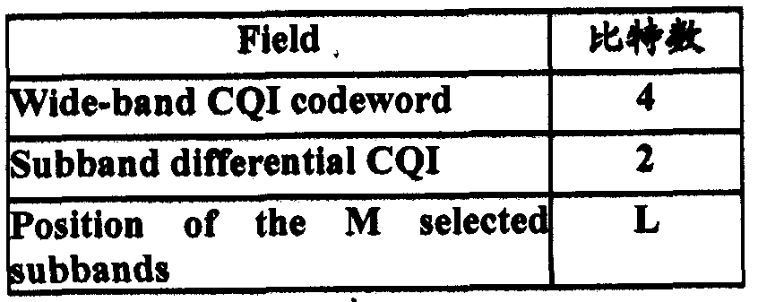

表 4
反馈模式 3-0为 "高层配置子带无 ΡΜΓ 的方式, 包含一个宽带的 CQI 信息 (4bits)和 N个差分的子带 CQI信息 (每个 2bits) , 如表 5所示:


表 6
在 PUSCH中, RI信息单独编码、 CQI + PMI信息单独编码, ACK或者 NACK信息也是单独编码, 这些上行控制信息一起与上行数据进行复用, 如 图 la所示。
复用和交织之后,进行上行数据符号至物理资源的映射,先映射 CQI/PMI 信息, 再在剩余资源映射上行数据。 ACK/NACK以及 RI信息是通过对上行 数据进行打孔映射的, 在导频两侧的四列符号先时域后频域从低频到高频放 置 ACK/NACK、 紧挨着 ACK/NACK的四列符号先时域后频域从低频到高频 映射 RI信息, 如图 lb所示。
在 LTE R8系统中, PUSCH中的非周期的 CQI/PMI/RI发送是通过 DCI Format 0中的 lbit CQI Request( CQI请求)信息触发的。 UE查收到 DCI format 0中该信息位置位 1,则按照前述预先配置的反馈模式组织相关的 CQI/PMI/RI 信息插入 PUSCH中发送, 否则不发送。 LTE R9中反馈模式的定义和 LTE R8 相同, 这里不再详细说明。
对于先进的长期演进( LTE-Advanced, LTE-A ) 系统, 为支持比 LTE系 统更宽的系统带宽, 比如 100MHz, 需要通过将多个 LTE栽波 (又称成员栽波) 的资源连接起来使用, 具体有两种方式: 将多个连续的 LTE载波进行聚合,
为 LTE-A提供更大的传输带宽;将多个不连续的 LTE栽波进行聚合,为 LTE-A 提供更大的传输带宽, 图 2给出了不连续栽波聚合的例子。
目前标准化组织的研究倾向为, 对于栽波聚合系统设计的共识是每个栽 波上的设计保持与 LTE Release 8尽量一致,从而保证 R8的 UE能够在每一个 成员载波上正常工作。
目前 LTE-A系统研究需求已经制定, 最大支持 5个成员栽波的聚合, 并 且, 一个 UE最大支持在 5个成员栽波上同时接》l 发送数据,
在载波聚合的研究中, 已经决定支持上下行非对称以及对称的栽波聚合。 对称和非对称的栽波聚合可以是系统角度配置的, 即系统中支持上下行对称 或非对称的栽波配置; 也可以是基于 UE进行分配的, 即一个 UE被分配为上 下行对称或非对称的栽波配置。 同时, 在栽波聚合的研究中, 也有一些提案 提出上下行栽波之间的配对问题, 如图 3a和 3b所示, 上行栽波和下行载波 之间有箭头连接表示两者存在配对关系, 一个下行栽波可以与一个或多个上 行栽波配对, 反之一个上行栽波也可以与一个或多个下行栽波配对。 这一配 对关系可以 ^^于系统的 (即系统中仅存在一组配对关系), 也可以是基于 UE 的 (即不同用户可以配置不同的配对关系)。
综上所述, 在 LTE-A系统中, 由于有限的频谱资源, 分配频谱资源时, 釆用多个载波部分聚合的技术, 其中多个栽波部分可能连续或者非连续的分 布在频谱资源上, 而且每个栽波部分的特性应符合目前 LTE标准中的基本要 求。 为了在 LTE-A栽波聚合系统中有效的执行栽波调度和链路自适应过程, 基站需要获得 UE测量的多个栽波的信道信息反馈, 以此进行多载波调度。其 中信道信息可以包括, 例如 RI信息, 宽带 CQI/PMI信息, 子带 CQI信息等。 但是, LTE Rel-8/9协议仅支持单栽波的信道信息反馈, 在 LTE-A栽波聚合情 况下多载波的非周期信道信息反馈的尚未有设计方案给出。 发明内容
本发明提供一种反馈多栽波信道信息的方法及装置, 用以实现多栽波的
非周期信道信息的反馈。
本发明实施例提供的一种反馈多栽波信道信息的方法, 包括:
UE在多个下行栽波上进行信道信息测量;
UE收到基站发送的反馈信道信息的触发指示后,根据获得的需要测量和 反馈的下行栽波集合, 将测量的相应的下行栽波的信道信息发送给基站。
本发明实施例提供的一种反馈多栽波信道信息的装置, 包括:
第一接收单元, 用于接收基站发送的需要测量和反馈的下行载波集合; 第二接收单元, 用于接收基站发送的反馈信道信息的触发指示; 测量单元, 用于在接收基站发送的反馈信道信息的触发指示后, 根据所 述需要测量和反饿的下行栽波集合, 进行信道测量;
反馈单元, 用于将测量的下行栽波的信道信息发送给基站。
本发明实施例提供的一种调度信道信息反馈的方法, 包括:
基站通知 UE需要测量和反馈的下行链路栽波集合;
基站向该 UE发送用于触发测量下行信道信息的消息, 所述下行信道信 息为所迷下行链路栽波集合中下行链路栽波的信道信息;
基站接收 UE测量的下行栽波的信道信息。
本发明实施例提供的一种调度信道信息反馈的装置, 包括:
第一发送单元, 用于通知 UE需要测量和反馈的下行链路栽波集合; 第二发送单元, 用于向该 UE发送用于触发测量下行信道信息的消息, 所述下行信道信息为所述下行链路栽波集合中下行链路栽波的信道信息; 接收单元, 用于接收 UE测量的下行栽波的信道信息。
本发明实施例中, UE在多个下行栽波上进行信道信息测量; UE收到基 站发送的反馈信道信息的触发指示后, 根据获得的需要测量和反馈的下行栽 波集合, 将测量的相应的下行栽波的信道信息发送给基站, 进而实现多栽波 信道信息的反馈。 发明内容
图 la为单栽波系统中 UCI与上行数据复用过程示意图;
图 lb 为单栽波系统中上行控制信息在上行物理资源的映射示意图; 图 2为栽波聚合示意图;
图 3a为上下行非对称聚合以及栽波配对示意图; 图 3b为上下行对称聚 合以及载波配对示意图;
图 4为本发明实施例为实现调度反馈信道信息, 基站侧执行的方法流程 示意图;
图 5为本发明实施例为实现反馈信道信息, UE侧执行的方法流程示意图; 图 6为本发明实施例实现调度反馈信道信息的装置结构示意图; 图 7为本发明实施例实现反馈信道信息的装置结构示意图;
图 8a为本发明实施例一的多栽波的信道质量信息与上行数据复用过程示 意图;
图 8b为本发明实施例一的多栽波信道信息反馈映射的示意图;
图 9a为本发明实施例二的多载波的信道盾量信息与上行数据复用过程示 意图;
图 9b为本发明实施例二的多载波信道信息反馈映射的示意图;
图 10a为本发明实施例三的多载波的信道盾量信息与上行数据复用过程 示意图;
图 10b为本发明实施例三的多栽波信道信息反馈映射的示意图。 具体实施方式
在本发明实施例中, 为了实现多栽波信道信息反馈,基站预先通知 UE需 要测量和反馈的下行链路栽波集合; 基站向该 UE发送用于触发测量下行信 道信息的消息, 以触发 UE对下行栽波的信道进行测量; UE收到基站发送的 反馈信道信息的触发指示后, 根据获得的需要测量和反馈的下行栽波集合将 测量的对应的下行载波的信道信息发送给基站。
参见图 4所示, 本发明为实现调度多栽波信道信息的反馈, 基站侧执行
的方法包括以下步骤:
步驟 401: 基站通知 UE需要测量和反馈的下行链路栽波集合。
基站可以通过高层信令向该 UE发送下行链路栽波集合。
步骤 402: 基站向该 UE发送用于触发测量下行信道信息的消息, 所述下 行信道信息为所述下行链路栽波集合中下行链路栽波的信道信息;
所述用于触发测量下行信道信息的消息可以为 DCI ( Downlink Control Information , 下行控制信息) 消息, 比如为 DCI格式 0。
步骤 403: 基站接收 UE测量的下行栽波的信道信息。
步骤 403 中, 将提取的物理资源上的数据符号进行解交织、 解复用和解 码, 得到每个下行栽波的信道信息。
参见图 5所示, 本发明为实现调度多栽波信道信息的反馈, UE侧执行的 方法包括以下步骤:
步骤 501: UE在多个下行栽波上进行信道信息测量。
步骤 502: UE收到基站发送的反馈信道信息的触发指示后, 根据获得的 需要测量和反馈的下行栽波集合, 将测量得到的对应下行栽波的信道信息发 送给基站。
所述需要测量和反馈的下行栽波集合可以是基站通过高层信令配置给 UE的, 比如: 基站预先发送高层信令给 UE, 其中含有需要测量和反馈的下 行栽波集合, 高层信令例如可以是 RRC (Radio Resource Control, 无线资源控 制)信令。
步骤 502 的一种发送方式是: 所述下行栽波的信道信息可以包括若干种 类的信道反馈信息, 而且如果在所述反馈信道信息的触发指示中可以包括载 波编号指示信息, 用于指示每种下行载波的信道信息反馈所占用的上行栽 波, 因此, 所述 UE将测量的下行栽波的信道信息可以通过对应的上行栽波 发送给基站。
所迷下行栽波的信道信息可以包括: CQI、 PMI和 RI三种信道反馈信息 中的一种或几种.
步骤 502 的另一种发送方式是: 如果在所述反馈信道信息的触发指示中 没有明确载波编号指示信息, 则所述 UE接收基站通知的下行栽波和上行载 波的配对情况信息, UE 可以将测量的下行栽波的信道信息通过对应的下行 栽波配对的上行栽波发送给基站。
所述反馈信道信息的触发指示可以为 DCI格式 0。
步骤 502中可 UE可以将测量的下行栽波的信道信息与需要发送的上行数 据进行复用、 交织处理; 将交织处理后得到的上行数据符号映射到相应的物 理资源上发送,
UE将测量的下行栽波的信道信息与需要发送的上行数据进行复用、 交 织处理可以包括艮多种实现方式:
第一种: 将经过信道编码和速率匹配后的业务数据进行码块级联处理, 并将每个下行栽波的 CQI/PMI信息单独进行信道编码; 将单独经过信道编码 用; 将经过复用处理后的数据、 经过单独编码的每个下行栽波的 RI信息以及 ACK/NACK信息单独编码后进行交织处理。
因此, 进行上行数据符号到物理资源映射时, 首先在物理资源上以 RE ( Resource Element, 资源单元)为单位, 以先时域后频域的方式顺序映射各 个载波单独的 CQI/PMI信息, 每个载波的 CQI/PMI信息占用的资源单元不 同, 在剩余物理资源映射上行数据, 并将 ACK/NACK和 RI信息通过对上行 数据进行打孔映射到物理资源上。 比如: RI信息按照 LTE R8 已经规定的规 则映射在 DMRS ( Demodulation Reference Signal, 上行专用导频) 两侧的 Single carrier SC-FDMA ( Frequency Division Multiple Access , 单栽波频分复 用)符号上, 不同栽波的 RI信息从低频至高频顺序映射在不同的资源单元, 且, 每个栽波的 RI信息所占用的资源单元不同。
第二种方式: 将经过信道编码和速率匹配后的业务数据进行码块级联处 理, 并将所述下行载波集合中的下行载波的 CQI/PMI信息进行联合编码; 将 经过联合编码的下行栽波的 CQI/PMI信息以及经过码块级联处理后的业务数
据进行复用; 将经过复用处理后的数据、 经过联合编码的下行栽波的 RI信息 以及经过单独编码的 ACK/NACK信息进行交织处理。 因此, 进行上行数据 符号到物理资源映射时, 首先在物理资源上以 RE 为单位, 以先时域后频域 的方式顺序映射各个栽波联合的 CQI/PMI信息, 各个载波的 CQI/PMI信息占 用的资源单元相同, 在剩余物理资源映射上行数据, 并将 ACK/NACK和 RI 信息通过对上行数据进行打孔映射到物理资源上, 且, 各个栽波联合的 RI信 息所占用的资源单元相同。
第三种: 将经过信道编码和速率匹配后的业务数据进行码块级联处理, 并将所述下行载波集合中下行栽波的 CQI/PMI信息进行联合编码; 将经过联 复用; 将经过复用处理后的数据、 经过单独编码的每个下行载波的 RI信息以 及经过单独编码的 ACK/NACK信息进行交织处理。 进行上行数据符号到物 理资源映射时, 首先在物理资源上以 RE 为单位, 以先时域后频域的方式顺 序映射各个栽波联合的 CQI/PMI信息, 各个栽波的 CQI/PMI信息占用的资源 单元相同, 在剩余物理资源映射上行数据, 并将 ACK/NACK和 RI信息通过 对上行数据进行打孔映射到物理资源上, 且, 每个栽波的 RI信息所占用的资 源单元不同。
参见图 6所示, 本发明实施例的一种调度信道信息反馈的装置结构示意 图, 包括: 第一发送单元 61、 第二发送单元 62和接收单元 63。
第一发送单元 61, 用于通知 UE需要测量和反馈的下行链路栽波集合; 第二发送单元 62, 用于向该 UE发送用于触发测量下行信道信息的消 息, 所述下行信道信息为所述下行链路栽波集合中下行链路栽波的信道信 息;
接收单元 63, 用于接收 UE测量的下行栽波的信道信息。
第一发送单元 61, 用于通过高层信令向该 UE发送下行链路栽波集合。 所述高层信令可以为 RRC信令。 所述用于触发测量下行信道信息的消息 可以为 DCI消息。
所述接收单元 63, 可以将提取的物理资源上的数据符号进行解交织、 解 复用和解码, 得到每个下行栽波的信道信息。
参见图 7 所示, 本发明实施例的一种反馈多栽波信道信息的装置, 包 括:
第一接收单元 71 , 用于接收基站发送的需要测量和反馈的下行栽波集 合;
第二接收单元 72, 用于接收基站发送的反馈信道信息的触发指示; 测量单元 73, 用于在多个下行栽波上进行信道信息测量; 进行信道测 量;
反馈单元 74, 用于在接收基站发送的反馈信道信息的触发指示后, 根据 所述需要测量和反馈的下行栽波集合, 将测量的对应的下行栽波的信道信息 发送给基站。
所述第一接收单元 71, 用于是从接收到的基站发送的高层信令中获得需 要测量和反馈的下行栽波集合。
所述下行栽波的信道信息包括若干种类的信道反馈信息, 所述反馈信道 信息的触发指示中包括栽波编号指示信息, 用于指示每种下行栽波的信道信 息反馈所占用的上行载波, 则所述反馈单元 74, 用于将测量的下行栽波的信 道信息通过对应的上行栽波发送给基站。
所述下行栽波的信道信息包括: CQI、 PMI和 RI三种信道反馈信息中的 一种或几种。
所述反馈单元, 用于根据基站通知的下行栽波和上行栽波的配对情况信 息, 将测量的下行栽波的信道信息通过对应的下行栽波配对的上行栽波发送 给基站。 所述反馈信道信息的触发指示为下行控制信息 DCI格式 0。
所述反馈单元 74, 可以将测量的下行栽波的信道信息与需要发送的上行 数据进行复用、 交织处理; 将交织处理后得到的上行数据符号映射到相应的 物理资源上发送。
所述反馈单元 74, 可以将经过信道编码和速率匹配后的业务数据进行码
块级联处理, 并将每个下行栽波的 CQI/PMI信息单独进行信道编码; 将单独 经过信道编码的每个下行栽波的 CQI/PMI信息以及经过码块级联处理后的业 务数据进行复用; 将经过复用处理后的数据、 经过单独编码的每个下行载波 的 RI信息以及 ACK/NACK信息单独编码后进行交织处理。 所述反馈单元 74 进行上行数据符号到物理资源映射时, 首先在物理资源上以 RE 为单位, 以 先时域后频域的方式顺序映射各个栽波单独的 CQI/PMI信息, 每个栽波的 CQI/PMI信息占用的资源单元不同, 在剩余物理资源映射上行数据, 并将 所述反馈单元 74, 用于将经过信道编码和速率匹配后的业务数据进行码 块级联处理, 并将所述下行栽波集合中的下行栽波的 CQI/PMI信息进行联合 编码; 将经过联合编码的下行栽波的 CQI/PMI信息以及经过码块级联处理后 的业务数据进行复用; 将经过复用处理后的数据、 经过联合编码的下行载波 的 RI信息以及经过单独编码的 ACK/NACK信息进行交织处理。
所述反债单元 74进行上行数据符号到物理资源映射时, 首先在物理资源 上以 RE为单位, 以先时域后频域的方式顺序映射各个栽波联合的 CQI/PMI 信息, 各个载波的 CQI/PMI信息占用的资源单元相同, 在剩余物理资源映射 上行数据, 并将 ACK/NACK和 RI信息通过对上行数据进行打孔映射到物理 资源上, 且, 各个栽波联合的 RI信息所占用的资源单元相同,
所述反馈单元 74, 用于将经过信道编码和速率匹配后的业务数据进行码 块级联处理, 并将所述下行栽波集合中下行栽波的 CQI/PMI信息进行联合编 码; 将经过联合编码的下行栽波的 CQI/PMI信息以及经过码块级联处理后的 业务数据进行复用; 将经过复用处理后的数据、 经过单独编码的每个下行栽 波的 RI信息以及经过单独编码的 ACK/NACK信息进行交织处理。
所述反馈单元 74进行上行数据符号到物理资源映射时, 首先在物理资源 上以 RE为单位, 以先时域后频域的方式顺序映射各个栽波联合的 CQI/PMI 信息, 各个载波的 CQI/PMI信息占用的资源单元相同, 在剩余物理资源映射 上行数据, 并将 ACK/NACK和 RI信息通过对上行数据进行打孔映射到物理
资源上, 且, 每个载波的 RI信息所占用的资源单元不同。
下面举实施例详细说明本发明的技术方案。
在本发明实施例中, LTE-A系统中, 当 UE配置了进行载波聚合时,使用 非周期的 CQI/PMI/RI反馈需要支持多栽波。 首先基站需要为不同的 DL CC ( Down Link Component Carrier, 下行链路成员栽波)配置非周期反馈模式, 各个 CC的反馈模式可以相同或不同, 具体的模式与 LTE R8/9相同。
在基站需要调度 UE对多个 DL CC的信道信息进行反馈时, 基站可以通 并在 DCI format 0中使用 lbit CQI Request信令触发该集合内的所有 CC的 CQI/PMI/m反馈; 同时, DCI format 0中的 CIF (Carrier Indication Field, 栽波 编号指示)用于指示 CQI/PMI/RI反馈是在哪个 UL CC上发送; 如果 CIF不存 在,则在与 DCI Format 0所在的 DL CC配对的 UL CC发送反馈信息。其中高 层信令可以使用 UE专属的 RRC信令。 UE根据 DCI format 0的触发在高层配 置的 UL CC ( Up Link Component Carrier, 上行链路成员栽波)反馈相应的 DL CC集合的 CQI/PMI/RI信息。
将 DCI Format 0中的 CQI request信令扩展至多比特, 用于指示一次非周 期反馈具体需要包含哪些 DL CC的 CQI/PMI/RI信息, 例如 LTE-A支持最多 5个 DL CC聚合, 那么使用 5bits的 CQI request信息采用位图 bitmap方式指 示一次非周期反馈具体包含哪些 DL CC的信道信息。 即: 所述需要测量和反 馈的下行栽波集合,在所述 DCI格式 0的信道质量指示符 CQI请求信令中扩 展的多个比特上, 采用位图 bitmap方式指示。
基站调度 UE进行非周期信道信息反馈时, 在一个 UL CC内反馈与其配 对的所有 DL CC的信道信息。
当 UE确定需要反馈的 DL CC集合后, UE需要将反馈信息与上行数据进 行复用。 具体做法是基于 LTE R8的基础上进行了多栽波的扩展。 如图 8a所 示, 将经过信道编码和速率匹配后的业务数据进行码块级联处理, 并将每个 下行载波的 CQI/PMI信息单独进行信道编码; 将单独经过信道编码的每个下
行栽波的 CQI/PMI信息以及经过码块级联处理后的业务数据进行复用; 将经 过复用处理后的数据、 经过单独编码的每个下行栽波的 RI 信息以及 ACK7NACK信息单独编码后进行交织处理。
如图 8b所示。 在映射过程中, 根据高层配置的反馈模式, DL CC集合内 的每一个 DL CC的 CQI/PMI信息单独编码,具体编码方式与 LTE R8/R9保持 相同, 然后统一与上行数据进行复用操作, 复用保证 CQI/PMI信息在上行数 据之前, 且不同 DL CC的 CQI/PMI信息进行顺序映射 (先时域后频域), 数据 与控制复用后的数据序列与各个 DL CC的 RI信息进入信道交织器,交织器的 输出保证 RI仍然位于与 LTE R8相同的符号位置上,且, 每个栽波的 RI信息 所占用的资源单元不同, 每个载波的 CQI/PMI信息占用的资源单元不同。 比 如: 不同栽波的 RI信息从低频至高频顺序映射在不同的资源单元。
在上面的例子中, 各个栽波的 CQI/PMI信息是单独编码的, 同时各个栽 波 RI信息也是单独编码的。实际上各个栽波的 CQI/PMI信息也可以是联合编 码处理, 同时各个栽波的 RI信息也可以是联合编码处理的。但 CQI/PMI信息 与 RI信息之间一定是单独编码的, 这是为了保证 RI信息更高的可靠性。
参见图 9a和 9b所示, 各个栽波的 CQI/PMI信息联合编码、 同时各个栽 波的 RI信息联合编码。
参见图 9a所示在本实施例中, 可以将经过信道编码和速率匹配后的业务 数据进行码块级联处理, 并将所述下行栽波集合中的下行栽波的 CQI/PMI信 息进行联合编码; 将经过联合编码的下行栽波的 CQI/PMI信息以及经过码块 级联处理后的业务数据进行复用; 将经过复用处理后的数据、 经过联合编码 的下行栽波的 RI信息以及经过单独编码的 ACK/NACK信息进行交织处理。
参见图 9b所示, 在映射过程中, 进行上行数据符号到物理资源映射时, 首先在物理资源上以 RE 为单位, 以先时域后频域的方式顺序映射各个载波 联合的 CQI/PMI信息, 各个栽波的 CQI/PMI信息占用的资源单元相同, 在剩 余物理资源映射上行数据, 并将 ACK/NACK和 RI信息通过对上行数据进行 打孔映射到物理资源上, 且, 各个栽波联合的 RI信息所占用的资源单元相
同。
参见图 10a和 10b所示, 各个载波的 CQI/PMI信息联合编码、 同时各个 栽波的 RI信息单独编码。
参见图 10a所示, 第三种: 将经过信道编码和速率匹配后的业务数据进 行码块级联处理, 并将所述下行栽波集合中下行栽波的 CQI/PMI信息进行联 合编码; 将经过联合编码的下行栽波的 CQI/PMI信息以及经过码块级联处理 后的业务数据进行复用; 将经过复用处理后的数据、 经过单独编码的每个下 行载波的 RI信息以及经过单独编码的 ACK NACK信息进行交织处理。
参见图 10b所示,在映射过程中, 首先在物理资源上以 RE为单位, 以先 时域后频域的方式顺序映射各个栽波联合的 CQI/PMI信息, 各个栽波的 CQI/PMI信息占用的资源单元相同, 在剩余物理资源映射上行数据, 并将 ACK/NACK和 RI信息通过对上行数据进行打孔映射到物理资源上, 且, 每 个载波的 RI信息所占用的资源单元不同。
在本发明实施例中, 可以使用非周期 PUSCH反馈多栽波的 CQI/PMI/RI 信息, 并且可以将多栽波信道信息与上行数椐复用后发送给基站。 其中, 各 个 CC的 CQI/PMI信息可以单独编码, 同时各个 CC的 RI信息单独编码; 各 个 CC的 CQI PMI信息也可以联合编码, 同时各个 CC的 RI信息联合编鸡; 各个 CC的 CQI/PMI信息还可以联合编码,同时各个 CC的 RI信息单独编码。
本领域内的技术人员应明白, 本发明的实施例可提供为方法、 系统、 或 计算机程序产品。 因此, 本发明可采用完全硬件实施例、 完全软件实施例、 或结合软件和硬件方面的实施例的形式。 而且, 本发明可采用在一个或多个 其中包含有计算机可用程序代码的计算机可用存储介盾 (包括但不限于磁盘 存储器、 CD-ROM、 光学存储器等)上实施的计算机程序产品的形式。
本发明是参照根据本发明实施例的方法、 设备(系统)、 和计算机程序产 品的流程图和 /或方框图来描述的。 应理解可由计算机程序指令实现流程图 和 /或方框图中的每一流程和 /或方框、 以及流程图和 /或方框图中的流程 和 /或方框的结合。 可提供这些计算机程序指令到通用计算机、 专用计算机、
嵌入式处理机或其他可编程数据处理设备的处理器以产生一个机器, 使得通 过计算机或其他可编程数据处理设备的处理器执行的指令产生用于实现在流 程图一个流程或多个流程和 /或方框图一个方框或多个方框中指定的功能的 装置。
这些计算机程序指令也可存储在能引导计算机或其他可编程数据处理设 备以特定方式工作的计算机可读存储器中, 使得存储在该计算机可读存储器 中的指令产生包括指令装置的制造品, 该指令装置实现在流程图一个流程或 多个流程和 /或方框图一个方框或多个方框中指定的功能。
这些计算机程序指令也可装栽到计算机或其他可编程数据处理设备上, 使得在计算机或其他可编程设备上执行一系列操作步骤以产生计算机实现的 处理, 从而在计算机或其他可编程设备上执行的指令提供用于实现在流程图 一个流程或多个流程和 /或方框图一个方框或多个方框中指定的功能的步 骤。
尽管已描述了本发明的优选实施例, 但本领域内的技术人员一旦得知了 基本创造性概念, 则可对这些实施例作出另外的变更和修改。 所以, 所附权 利要求意欲解释为包括优选实施例以及落入本发明范围的所有变更和修改。
显然, 本领域的技术人员可以对本发明进行各种改动和变型而不脱离本 发明的精神和范围。 这样, 倘若本发明的这些修改和变型属于本发明权利要 求及其等同技术的范围之内, 则本发明也意图包含这些改动和变型在内。
Claims
1、一种反馈多栽波信道信息的方法,其特征在于,该方法包括以下步骤: 终端在多个下行载波上进行信道信息测量;
终端收到基站发送的反馈信道信息的触发指示后, 根据获得的需要测量 和反馈的下行栽波集合, 将测量的相应下行栽波的信道信息发送给基站。
2、 根据权利要求 1所述的方法, 其特征在于, 所述需要测量和反馈的下 行载波集合是从接收到的基站发送的髙层信令中获得。
3、 根据权利要求 1所述的方法, 其特征在于, 所述下行栽波的信道信息 包括若干种类的信道反馈信息, 所述反馈信道信息的触发指示中包括栽波编 号指示信息, 用于指示每种下行栽波的信道信息反馈所占用的上行栽波, 则 站; 或者,
终端还接收基站通知的下行栽波和上行栽波的配对情况信息, 则所述终 送给基站。
4、 根据权利要求 1所述的方法, 其特征在于, 所述反馈信道信息的触发 指示为下行控制信息 DCI格式 0。
5、 根据权利要求 4所述的方法, 其特征在于, 所述需要测量和反馈的下 行栽波集合,在所述 DCI格式 0的信道质量指示符 CQI请求信令中扩展的多 个比特上, 采用位图 bitmap方式指示。
6、 根据权利要求 1~5任一所述的方法, 其特征在于, 所述下行栽波的信 道信息包括: 信道盾量指示符 CQI、预编码矩阵指示符 PMI和秩指示 RI三种 信道反馈信息中的一种或几种。
7、 根据权利要求 6所述的方法, 其特征在于, 终端将测量的下行栽波的 信道信息发送给基站, 包括:
终端将测量的下行栽波的信道信息与需要发送的上行数据进行复用、 交 织处理;
8、 根据权利要求 7所述的方法, 其特征在于, 终端将测量的下行栽波的 信道信息与需要发送的上行数据进行复用、 交织处理, 包括:
将经过信道编码和速率匹配后的业务数据进行码块级联处理, 并将每个 下行栽波的 CQI/P 信息单独进行信道编码;
将单独经过信道编码的每个下行栽波的 CQI/PMI信息以及经过码块级联 处理后的业务数据进行复用;
将经过复用处理后的数据、 经过单独编码的每个下行栽波的 RI信息以及 ACK/NACK信息单独编码后进行交织处理。
9、 根据权利要求 8所述的方法, 其特征在于, 将交织处理后得到的上行 数据符号映射到相应的物理资源上发送, 包括:
进行上行数据符号到物理资源映射时, 首先在物理资源上以资源单元 RE 为单位, 以先时域后频域的方式顺序映射各个栽波单独的 CQI/PMI信息, 每 个栽波的 CQI/PMI信息占用的资源单元不同,在剩余物理资源映射上行数据, 并将 ACK/NACK和 RI信息通过对上行数据进行打孔映射到物理资源上。
10、 根据权利要求 9所述的方法, 其特征在于, RI信息按照 LTE R8的 规则映射在上行专用导频 DMRS两侧的单栽波频分复用 SC-FDMA符号上, 不同载波的 RI信息从低频至高频顺序映射在不同的资源单元, 且, 每个载波 的 RI信息所占用的资源单元不同。
11、 根据权利要求 7所述的方法, 其特征在于, 终端将测量的下行栽波 的信道信息与需要发送的上行数据进行复用、 交织处理, 包括:
将经过信道编码和速率匹配后的业务数据进行码块级联处理, 并将所述 下行栽波集合中的下行栽波的 CQI/PMI信息进行联合编码;
将经过联合编码的下行栽波的 CQI/PMI信息以及经过码块级联处理后的 业务数据进行复用;
将经过复用处理后的数据、 经过联合编码的下行栽波的 RI信息以及经过 单独编码的 ACK/NACK信息进行交织处理。
12、 根据权利要求 11所述的方法, 其特征在于, 将交织处理后得到的上 行数据符号映射到相应的物理资源上发送, 包括:
进行上行数据符号到物理资源映射时, 首先在物理资源上以 RE为单位, 以先时域后频域的方式顺序映射各个栽波联合的 CQI/PMI信息, 各个栽波联 合编码后的 CQI/PMI信息占用的资源单元相同, 在剩余物理资源映射上行数 据,并将 ACK/NACK和 RI信息通过对上行数据进行打孔映射到物理资源上, 且, 各个栽波联合编码后的 RI信息所占用的资源单元相同。
13、 根据权利要求 7所述的方法, 其特征在于, 终端将测量的下行栽波 的信道信息与需要发送的上行数据进行复用、 交织处理, 包括:
将经过信道编码和速率匹配后的业务数据进行码块级联处理, 并将所述 下行载波集合中下行栽波的 CQI/PMI信息进行联合编码;
将经过联合编码的下行载波的 CQI/PMI信息以及经过码块级联处理后的 业务数据进行复用;
将经过复用处理后的数据、 经过单独编码的每个下行栽波的 RI信息以及 经过单独编码的 ACK/NACK信息进行交织处理。
14、 根据权利要求 13所述的方法, 其特征在于, 将交织处理后得到的上 行数据符号映射到相应的物理资源上发送, 包括:
进行上行数据符号到物理资源映射时, 首先在物理资源上以 RE为单位, 以先时域后频域的方式顺序映射各个载波联合编码的 CQI/PMI信息, 各个栽 波联合编码的 CQI/PMI信息占用的资源单元相同, 在剩余物理资源映射上行 数据, 并将 ACK/NACK和 RI信息通过对上行数据进行打孔映射到物理资源 上, 且, 每个栽波单独编码的 RI信息所占用的资源单元不同。
15、 一种反馈多栽波信道信息的装置, 其特征在于, 该装置包括: 第一接收单元, 用于接收基站发送的需要测量和反馈的下行载波集合; 第二接收单元, 用于接收基站发送的反馈信道信息的触发指示; 测量单元, 用于在多个下行栽波上进行信道信息测量; 进行信道测量; 反馈单元, 用于在接收基站发送的反馈信道信息的触发指示后, 根据所 述需要测量和反馈的下行栽波集合, 将测量的对应的下行栽波的信道信息发 送给基站。
16、 根据权利要求 15所述的装置, 其特征在于, 所述第一接收单元, 用 于是从接收到的基站发送的高层信令中获得需要测量和反馈的下行栽波集 合。
17、 根据权利要求 15所述的装置, 其特征在于, 所述下行栽波的信道信 息包括若干种类的信道反馈信息, 所述反馈信道信息的触发指示中包括栽波 编号指示信息, 用于指示每种下行栽波的信道信息反馈所占用的上行栽波, 则所述反馈单元, 用于将测量的下行栽波的信道信息通过对应的上行栽 波发送给基站。
18、 根据权利要求 15所述的装置, 其特征在于, 所述反馈单元, 用于根 据基站通知的下行栽波和上行栽波的配对情况信息, 将测量的下行栽波的信 道信息通过对应的下行载波配对的上行栽波发送给基站。
19、 根据权利要求 15所述的装置, 其特征在于, 所述反馈信道信息的触 发指示为下行控制信息 DCI格式 0。
20、 根椐权利要求 15〜19任一所述的装置, 其特征在于, 所述下行栽波 的信道信息包括: CQL PMI和 RI三种信道反馈信息中的一种或几种。
21、 根据权利要求 20所述的装置, 其特征在于, 所述反馈单元, 用于将 测量的下行载波的信道信息与需要发送的上行数据进行复用、 交织处理; 将 交织处理后得到的上行数据符号映射到相应的物理资源上发送。
22、 根据权利要求 21所述的装置, 其特征在于, 所述反馈单元, 用于将 经过信道编码和速率匹配后的业务数据进行码块级联处理, 并将每个下行栽 波的 CQI/PMI信息单独进行信道编码; 将单独经过信道编码的每个下行栽波 的 CQI/PMI信息以及经过码块级联处理后的业务数据进行复用; 将经过复用 处理后的数据、 经过单独编码的每个下行栽波的 RI信息以及 ACK/NACK信 息单独编码后进行交织处理。
23、 根据权利要求 22所述的装置, 其特征在于, 所述反馈单元, 用于进 行上行数据符号到物理资源映射时, 首先在物理资源上以 RE为单位, 以先时 域后频域的方式顺序映射各个栽波单独的 CQI/PMI 信息, 每个栽波的 CQI/PMI信息占用的资源单元不同, 在剩余物理资源映射上行数据, 并将 ACK/NACK和 RI信息通过对上行数据进行打孔映射到物理资源上。
24、 根据权利要求 23所述的装置, 其特征在于, 将 RI信息按照 LTE R8 规定的规则映射在上行 DMRS两侧的 SC-FDMA符号上,不同栽波的 RI信息 从低频至高频顺序映射在不同的资源单元, 且, 每个载波的 RI信息所占用的 资源单元不同,
25、 根据权利要求 22所述的装置, 其特征在于, 所述反馈单元, 用于将 经过信道编码和速率匹配后的业务数据进行码块级联处理, 并将所述下行栽 波集合中的下行栽波的 CQI/PMI信息进行联合编码; 将经过联合编码的下行 载波的 CQI/PMI信息以及经过码块级联处理后的业务数据进行复用; 将经过 复用处理后的数据、 经过联合编码的下行载波的 RI信息以及经过单独编码的 ACK/NACK信息进行交织处理。
26、 根据权利要求 25所述的装置, 其特征在于, 所述反馈单元, 用于进 行上行数据符号到物理资源映射时, 首先在物理资源上以 RE为单位, 以先时 域后频域的方式顺序映射各个栽波联合编码的 CQI/PMI信息, 各个载波的 CQI/PMI信息占用的资源单元相同, 在剩余物理资源映射上行数据, 并将 ACK/NACK和 RI信息通过对上行数据进行打孔映射到物理资源上, 且, 各 个栽波联合编码的 RI信息所占用的资源单元相同。
27、 根据权利要求 22所述的装置, 其特征在于, 所述反馈单元, 用于将 经过信道编码和速率匹配后的业务数据进行码块级联处理, 并将所述下行栽 波集合中下行栽波的 CQI/PMI信息进行联合编码; 将经过联合编码的下行载 波的 CQI/PMI信息以及经过码块级联处理后的业务数据进行复用; 将经过复 用处理后的数据、 经过单独编码的每个下行栽波的 RI信息以及经过单独编码 的 ACK/NACK信息进行交织处理。
28、 根据权利要求 27所述的装置, 其特征在于, 所述反馈单元, 用于进 行上行数据符号到物理资源映射时, 首先在物理资源上以 RE为单位, 以先时 域后频域的方式顺序映射各个栽波联合的 CQI/PMI 信息, 各个栽波的 CQI/PMI信息占用的资源单元相同, 在剩余物理资源映射上行数据, 并将 ACK/NACK和 RI信息通过对上行数据进行打孔映射到物理资源上, 且, 每 个载波的 RI信息所占用的资源单元不同。
29、 一种调度信道信息反馈的方法, 其特征在于, 该方法包括以下步骤: 基站通知终端需要测量和反馈的下行链路栽波集合;
基站向该终端发送用于触发测量下行信道信息的消息, 所迷下行信道信 息为所述下行链路载波集合中下行链路栽波的信道信息;
基站接收终端测量的下行栽波的信道信息。
30、 根据权利要求 29所述的方法, 其特征在于, 基站通知终端需要测量 和反馈的下行链路栽波集合, 包括:
基站通过高层信令向该终端发送下行链路栽波集合。
31、 根据权利要求 30所述的方法, 其特征在于, 所述高层信令为 RRC 信令。
32、 根据权利要求 29所述的方法, 其特征在于, 所述用于触发测量下行 信道信息的消息为 DCI消息。
33、 根据权利要求 29所述的方法, 其特征在于, 基站接收终端测量的下 行栽波的信道信息, 包括:
将提取的物理资源上的数据符号进行解交织、 解复用和解码, 得到每个 下行栽波的信道信息。
34、 一种调度信道信息反馈的装置, 其特征在于, 该装置包括: 第一发送单元, 用于通知终端需要测量和反馈的下行链路栽波集合; 第二发送单元, 用于向该终端发送用于触发测量下行信道信息的消息, 所述下行信道信息为所述下行链路栽波集合中下行链路栽波的信道信息; 接收单元, 用于接收终端测量的下行栽波的信道信息。
35、 根据权利要求 34所述的装置, 其特征在于, 第一发送单元, 用于通 过高层信令向该终端发送下行链路栽波集合。
36、 根据权利要求 35 所述的装置, 其特征在于, 所述高层信令为 RRC 信令。
37、 根据权利要求 34所述的装置, 其特征在于, 所述用于触发测量下行 信道信息的消息为 DCI消息。
38、 根据权利要求 34所述的装置, 其特征在于, 所述接收单元, 用于将 提取的物理资源上的数据符号进行解交织、 解复用和解码, 得到每个下行载 波的信道信息。
Priority Applications (2)
| Application Number | Priority Date | Filing Date | Title |
|---|---|---|---|
| EP10841989.6A EP2525598B1 (en) | 2010-01-11 | 2010-12-31 | Method and apparatus for feeding back multi-carrier channel information |
| US13/521,662 US9148248B2 (en) | 2010-01-11 | 2010-12-31 | Method and device for feeding back channel information of a plurality of carriers |
Applications Claiming Priority (2)
| Application Number | Priority Date | Filing Date | Title |
|---|---|---|---|
| CN201010033773.1 | 2010-01-11 | ||
| CN201010033773.1A CN102082625B (zh) | 2010-01-11 | 2010-01-11 | 一种反馈多载波信道信息的方法及装置 |
Publications (1)
| Publication Number | Publication Date |
|---|---|
| WO2011082646A1 true WO2011082646A1 (zh) | 2011-07-14 |
Family
ID=44088388
Family Applications (1)
| Application Number | Title | Priority Date | Filing Date |
|---|---|---|---|
| PCT/CN2010/080575 Ceased WO2011082646A1 (zh) | 2010-01-11 | 2010-12-31 | 一种反馈多载波信道信息的方法及装置 |
Country Status (4)
| Country | Link |
|---|---|
| US (1) | US9148248B2 (zh) |
| EP (1) | EP2525598B1 (zh) |
| CN (1) | CN102082625B (zh) |
| WO (1) | WO2011082646A1 (zh) |
Families Citing this family (23)
| Publication number | Priority date | Publication date | Assignee | Title |
|---|---|---|---|---|
| WO2011120432A1 (en) | 2010-03-31 | 2011-10-06 | Huawei Technologies Co., Ltd. | Method and apparatus of communication |
| CN108900288B (zh) | 2010-04-06 | 2023-09-05 | 北京璟石知识产权管理有限公司 | 信道状态信息的传输方法、装置及计算机可读存储介质 |
| WO2012015154A1 (ko) | 2010-07-26 | 2012-02-02 | 엘지전자 주식회사 | 다중 반송파 정합을 지원하는 무선 접속 시스템에서 비주기적 채널상태정보 피드백 방법 |
| CN102291764A (zh) * | 2011-08-05 | 2011-12-21 | 电信科学技术研究院 | 配置测量信息和进行上报的方法、系统及设备 |
| CN102291223B (zh) * | 2011-08-05 | 2014-03-12 | 电信科学技术研究院 | 信道状态信息反馈指示及反馈方法和设备 |
| CN102263613B (zh) * | 2011-08-08 | 2018-04-20 | 中兴通讯股份有限公司 | 一种信道状态信息反馈方法和装置 |
| BR112014001492A2 (pt) * | 2011-08-10 | 2017-02-14 | Fujitsu Ltd | sistema para relatar informações sobre o estado do canal, equipamento de usuário e estação base |
| EP2739107B1 (en) * | 2012-11-28 | 2019-01-02 | Samsung Electronics Co., Ltd | Method and apparatus for performing communication in a wireless communication system |
| KR102117024B1 (ko) | 2012-11-28 | 2020-06-01 | 삼성전자 주식회사 | 무선 통신 시스템의 통신 방법 및 장치 |
| CN103905165B (zh) * | 2012-12-28 | 2017-10-31 | 电信科学技术研究院 | 应答反馈信息的发送和接收方法及设备 |
| CN104125040A (zh) * | 2013-04-28 | 2014-10-29 | 华为技术有限公司 | 一种上行控制信息的传输方法及用户设备 |
| CN104135355A (zh) * | 2013-05-03 | 2014-11-05 | 索尼公司 | 通信装置、通信系统和通信方法 |
| CN104184560A (zh) * | 2013-05-24 | 2014-12-03 | 中兴通讯股份有限公司 | 信道状态信息反馈方法和终端 |
| US10433200B2 (en) * | 2014-12-09 | 2019-10-01 | Lg Electronics Inc. | Method for terminal for reporting channel status information in wireless communication system supporting carrier aggregation, and apparatus for the method |
| EP3282629B1 (en) * | 2015-04-08 | 2020-09-09 | LG Electronics Inc. | Method for reporting channel state and apparatus therefor |
| CN112994865B (zh) * | 2015-07-30 | 2024-05-31 | 苹果公司 | 用于通信的装置、方法和计算机可读介质 |
| CN113949484B (zh) * | 2015-08-14 | 2023-04-11 | 中兴通讯股份有限公司 | Dmrs端口或映射关系的通知、确定方法及装置 |
| US11412534B2 (en) | 2016-11-04 | 2022-08-09 | Qualcomm Incorporated | System and method for mapping uplink control information |
| CN110999238B (zh) * | 2017-06-15 | 2022-09-27 | 株式会社Ntt都科摩 | 用户终端以及无线通信方法 |
| CN110166183B (zh) | 2018-02-12 | 2022-07-29 | 华为技术有限公司 | 指示方法,网络设备及用户设备 |
| CN110972157B (zh) * | 2018-09-28 | 2021-10-15 | 华为技术有限公司 | 信息处理方法和终端设备 |
| WO2020167180A1 (en) * | 2019-02-15 | 2020-08-20 | Telefonaktiebolaget Lm Ericsson (Publ) | Acknowledgement signaling for radio access networks |
| US11877173B2 (en) * | 2020-05-20 | 2024-01-16 | Qualcomm Incorporated | Optimization of channel quality indicator (CQI) feedback for multiple component carriers |
Citations (3)
| Publication number | Priority date | Publication date | Assignee | Title |
|---|---|---|---|---|
| CN101005343A (zh) * | 2006-01-20 | 2007-07-25 | 华为技术有限公司 | 一种多载波信道资源的分配方法及系统 |
| WO2008127166A2 (en) * | 2007-04-13 | 2008-10-23 | Telefonaktiebolaget Lm Ericsson (Publ) | Multi-carrier cqi feedback method and apparatus |
| CN101621359A (zh) * | 2008-07-04 | 2010-01-06 | 华为技术有限公司 | 一种发送信道质量指示的方法、装置及系统 |
Family Cites Families (8)
| Publication number | Priority date | Publication date | Assignee | Title |
|---|---|---|---|---|
| US20080219370A1 (en) * | 2007-03-06 | 2008-09-11 | Texas Instruments Incorporated | User equipment feedback structures for mimo ofdma |
| US8457235B2 (en) * | 2007-06-25 | 2013-06-04 | Lg Electronics Inc. | Method of transmitting feedback data in multiple antenna system |
| KR100925444B1 (ko) | 2008-05-27 | 2009-11-06 | 엘지전자 주식회사 | 상향링크 채널을 통해 데이터와 제어 정보를 포함하는 상향링크 신호를 전송하는 방법 |
| US8406171B2 (en) * | 2008-08-01 | 2013-03-26 | Texas Instruments Incorporated | Network MIMO reporting, control signaling and transmission |
| KR101638900B1 (ko) * | 2008-08-05 | 2016-07-12 | 엘지전자 주식회사 | 무선 통신 시스템에서 하향링크 멀티 캐리어에 대한 제어정보를 전송하는 방법 |
| US8483076B2 (en) * | 2008-08-18 | 2013-07-09 | Qualcomm Incorporated | A-periodic PUCCH transmission on PUSCH |
| KR101678686B1 (ko) * | 2009-05-14 | 2016-11-24 | 엘지전자 주식회사 | 무선 통신 시스템에서 cqi 전송 방법 및 장치 |
| CN101594209A (zh) * | 2009-06-18 | 2009-12-02 | 中兴通讯股份有限公司 | 反馈状态的发送方法及终端 |
-
2010
- 2010-01-11 CN CN201010033773.1A patent/CN102082625B/zh active Active
- 2010-12-31 EP EP10841989.6A patent/EP2525598B1/en active Active
- 2010-12-31 US US13/521,662 patent/US9148248B2/en active Active
- 2010-12-31 WO PCT/CN2010/080575 patent/WO2011082646A1/zh not_active Ceased
Patent Citations (3)
| Publication number | Priority date | Publication date | Assignee | Title |
|---|---|---|---|---|
| CN101005343A (zh) * | 2006-01-20 | 2007-07-25 | 华为技术有限公司 | 一种多载波信道资源的分配方法及系统 |
| WO2008127166A2 (en) * | 2007-04-13 | 2008-10-23 | Telefonaktiebolaget Lm Ericsson (Publ) | Multi-carrier cqi feedback method and apparatus |
| CN101621359A (zh) * | 2008-07-04 | 2010-01-06 | 华为技术有限公司 | 一种发送信道质量指示的方法、装置及系统 |
Also Published As
| Publication number | Publication date |
|---|---|
| EP2525598A4 (en) | 2013-05-15 |
| US9148248B2 (en) | 2015-09-29 |
| EP2525598B1 (en) | 2015-02-18 |
| CN102082625B (zh) | 2014-10-22 |
| CN102082625A (zh) | 2011-06-01 |
| US20130039197A1 (en) | 2013-02-14 |
| EP2525598A1 (en) | 2012-11-21 |
Similar Documents
| Publication | Publication Date | Title |
|---|---|---|
| WO2011082646A1 (zh) | 一种反馈多载波信道信息的方法及装置 | |
| US20240064748A1 (en) | Method and apparatus for uplink control signaling with massive carrier aggregation | |
| JP6851440B2 (ja) | 複数キャリアのチャネル状態情報の伝送 | |
| KR102722627B1 (ko) | 무선 통신 시스템에서 기준 신호 송수신 방법 및 장치 | |
| CN109478979B (zh) | 无线蜂窝通信系统中设置多个dmrs结构的方法和设备 | |
| JP6019091B2 (ja) | アップリンク制御情報のためのユーザ機器、基地局装置、および集積回路 | |
| US20230111063A1 (en) | Method and apparatus for transmitting or receiving reference signal in wireless communication system | |
| KR102316775B1 (ko) | 무선 셀룰라 통신 시스템에서 전송시간구간 감소를 위한 송수신 방법 및 장치 | |
| CN107196743B (zh) | 在无线通信系统中控制上行链路控制信息的方法和装置 | |
| CN105490781B (zh) | 传输控制信息的方法、用户设备和基站 | |
| CN102959890B (zh) | 载波聚合中用于信道状态反馈的系统和方法 | |
| CN113765629B (zh) | 无线通信系统中的基站和终端及其信号发送和接收方法 | |
| CN104054292B (zh) | 用于通过上行链路发送控制信息的方法和装置 | |
| CN115765927A (zh) | 用于多流传输的方法和设备 | |
| CN115134062B (zh) | 无线蜂窝通信系统中设置多个dmrs结构的方法和设备 | |
| KR20230163533A (ko) | 물리적 업링크 제어 채널(pucch)에 대한 혼합된 우선순위들을 갖는 업링크 제어 정보(uci)의 다중화 | |
| KR20140009995A (ko) | 무선 통신 시스템에서 단말이 기지국으로 채널 상태 정보를 전송하는 방법 및 이를 위한 장치 | |
| WO2012057480A2 (ko) | 무선 통신 시스템에서 제어 정보를 송신하는 방법 및 이를 위한 장치 | |
| KR20220135577A (ko) | 무선 통신 시스템에서 상향링크 채널 전송을 위한 방법 및 장치 |
Legal Events
| Date | Code | Title | Description |
|---|---|---|---|
| 121 | Ep: the epo has been informed by wipo that ep was designated in this application |
Ref document number: 10841989 Country of ref document: EP Kind code of ref document: A1 |
|
| NENP | Non-entry into the national phase |
Ref country code: DE |
|
| WWE | Wipo information: entry into national phase |
Ref document number: 13521662 Country of ref document: US |
|
| WWE | Wipo information: entry into national phase |
Ref document number: 2010841989 Country of ref document: EP |