WO2011083794A1 - 無線基地局装置、移動端末装置及び無線通信方法 - Google Patents
無線基地局装置、移動端末装置及び無線通信方法 Download PDFInfo
- Publication number
- WO2011083794A1 WO2011083794A1 PCT/JP2011/050035 JP2011050035W WO2011083794A1 WO 2011083794 A1 WO2011083794 A1 WO 2011083794A1 JP 2011050035 W JP2011050035 W JP 2011050035W WO 2011083794 A1 WO2011083794 A1 WO 2011083794A1
- Authority
- WO
- WIPO (PCT)
- Prior art keywords
- channel quality
- orthogonalization
- csi
- base station
- reference signal
- Prior art date
- Legal status (The legal status is an assumption and is not a legal conclusion. Google has not performed a legal analysis and makes no representation as to the accuracy of the status listed.)
- Ceased
Links
Images
Classifications
-
- H—ELECTRICITY
- H04—ELECTRIC COMMUNICATION TECHNIQUE
- H04J—MULTIPLEX COMMUNICATION
- H04J11/00—Orthogonal multiplex systems, e.g. using WALSH codes
- H04J11/0023—Interference mitigation or co-ordination
- H04J11/005—Interference mitigation or co-ordination of intercell interference
- H04J11/0056—Inter-base station aspects
-
- H—ELECTRICITY
- H04—ELECTRIC COMMUNICATION TECHNIQUE
- H04J—MULTIPLEX COMMUNICATION
- H04J11/00—Orthogonal multiplex systems, e.g. using WALSH codes
- H04J11/0023—Interference mitigation or co-ordination
- H04J11/005—Interference mitigation or co-ordination of intercell interference
-
- H—ELECTRICITY
- H04—ELECTRIC COMMUNICATION TECHNIQUE
- H04J—MULTIPLEX COMMUNICATION
- H04J11/00—Orthogonal multiplex systems, e.g. using WALSH codes
- H04J11/0023—Interference mitigation or co-ordination
- H04J11/005—Interference mitigation or co-ordination of intercell interference
- H04J11/0053—Interference mitigation or co-ordination of intercell interference using co-ordinated multipoint transmission/reception
-
- H—ELECTRICITY
- H04—ELECTRIC COMMUNICATION TECHNIQUE
- H04L—TRANSMISSION OF DIGITAL INFORMATION, e.g. TELEGRAPHIC COMMUNICATION
- H04L25/00—Baseband systems
- H04L25/02—Details ; arrangements for supplying electrical power along data transmission lines
- H04L25/0202—Channel estimation
- H04L25/0224—Channel estimation using sounding signals
- H04L25/0226—Channel estimation using sounding signals sounding signals per se
-
- H—ELECTRICITY
- H04—ELECTRIC COMMUNICATION TECHNIQUE
- H04L—TRANSMISSION OF DIGITAL INFORMATION, e.g. TELEGRAPHIC COMMUNICATION
- H04L5/00—Arrangements affording multiple use of the transmission path
- H04L5/0001—Arrangements for dividing the transmission path
- H04L5/0003—Two-dimensional division
- H04L5/0005—Time-frequency
- H04L5/0007—Time-frequency the frequencies being orthogonal, e.g. OFDM(A) or DMT
- H04L5/0012—Hopping in multicarrier systems
-
- H—ELECTRICITY
- H04—ELECTRIC COMMUNICATION TECHNIQUE
- H04L—TRANSMISSION OF DIGITAL INFORMATION, e.g. TELEGRAPHIC COMMUNICATION
- H04L5/00—Arrangements affording multiple use of the transmission path
- H04L5/0001—Arrangements for dividing the transmission path
- H04L5/0026—Division using four or more dimensions, e.g. beam steering or quasi-co-location [QCL]
-
- H—ELECTRICITY
- H04—ELECTRIC COMMUNICATION TECHNIQUE
- H04L—TRANSMISSION OF DIGITAL INFORMATION, e.g. TELEGRAPHIC COMMUNICATION
- H04L5/00—Arrangements affording multiple use of the transmission path
- H04L5/003—Arrangements for allocating sub-channels of the transmission path
- H04L5/0032—Distributed allocation, i.e. involving a plurality of allocating devices, each making partial allocation
- H04L5/0035—Resource allocation in a cooperative multipoint environment
-
- H—ELECTRICITY
- H04—ELECTRIC COMMUNICATION TECHNIQUE
- H04L—TRANSMISSION OF DIGITAL INFORMATION, e.g. TELEGRAPHIC COMMUNICATION
- H04L5/00—Arrangements affording multiple use of the transmission path
- H04L5/003—Arrangements for allocating sub-channels of the transmission path
- H04L5/0048—Allocation of pilot signals, i.e. of signals known to the receiver
-
- H—ELECTRICITY
- H04—ELECTRIC COMMUNICATION TECHNIQUE
- H04L—TRANSMISSION OF DIGITAL INFORMATION, e.g. TELEGRAPHIC COMMUNICATION
- H04L5/00—Arrangements affording multiple use of the transmission path
- H04L5/003—Arrangements for allocating sub-channels of the transmission path
- H04L5/0048—Allocation of pilot signals, i.e. of signals known to the receiver
- H04L5/0051—Allocation of pilot signals, i.e. of signals known to the receiver of dedicated pilots, i.e. pilots destined for a single user or terminal
-
- H—ELECTRICITY
- H04—ELECTRIC COMMUNICATION TECHNIQUE
- H04L—TRANSMISSION OF DIGITAL INFORMATION, e.g. TELEGRAPHIC COMMUNICATION
- H04L5/00—Arrangements affording multiple use of the transmission path
- H04L5/003—Arrangements for allocating sub-channels of the transmission path
- H04L5/0058—Allocation criteria
- H04L5/0073—Allocation arrangements that take into account other cell interferences
-
- H—ELECTRICITY
- H04—ELECTRIC COMMUNICATION TECHNIQUE
- H04W—WIRELESS COMMUNICATION NETWORKS
- H04W24/00—Supervisory, monitoring or testing arrangements
- H04W24/10—Scheduling measurement reports ; Arrangements for measurement reports
-
- H—ELECTRICITY
- H04—ELECTRIC COMMUNICATION TECHNIQUE
- H04L—TRANSMISSION OF DIGITAL INFORMATION, e.g. TELEGRAPHIC COMMUNICATION
- H04L27/00—Modulated-carrier systems
- H04L27/26—Systems using multi-frequency codes
- H04L27/2601—Multicarrier modulation systems
-
- H—ELECTRICITY
- H04—ELECTRIC COMMUNICATION TECHNIQUE
- H04L—TRANSMISSION OF DIGITAL INFORMATION, e.g. TELEGRAPHIC COMMUNICATION
- H04L5/00—Arrangements affording multiple use of the transmission path
- H04L5/0001—Arrangements for dividing the transmission path
- H04L5/0028—Variable division
-
- H—ELECTRICITY
- H04—ELECTRIC COMMUNICATION TECHNIQUE
- H04L—TRANSMISSION OF DIGITAL INFORMATION, e.g. TELEGRAPHIC COMMUNICATION
- H04L5/00—Arrangements affording multiple use of the transmission path
- H04L5/003—Arrangements for allocating sub-channels of the transmission path
- H04L5/0053—Allocation of signalling, i.e. of overhead other than pilot signals
- H04L5/0057—Physical resource allocation for CQI
-
- H—ELECTRICITY
- H04—ELECTRIC COMMUNICATION TECHNIQUE
- H04L—TRANSMISSION OF DIGITAL INFORMATION, e.g. TELEGRAPHIC COMMUNICATION
- H04L5/00—Arrangements affording multiple use of the transmission path
- H04L5/0091—Signalling for the administration of the divided path, e.g. signalling of configuration information
- H04L5/0092—Indication of how the channel is divided
-
- H—ELECTRICITY
- H04—ELECTRIC COMMUNICATION TECHNIQUE
- H04W—WIRELESS COMMUNICATION NETWORKS
- H04W28/00—Network traffic management; Network resource management
- H04W28/02—Traffic management, e.g. flow control or congestion control
- H04W28/04—Error control
-
- H—ELECTRICITY
- H04—ELECTRIC COMMUNICATION TECHNIQUE
- H04W—WIRELESS COMMUNICATION NETWORKS
- H04W48/00—Access restriction; Network selection; Access point selection
- H04W48/08—Access restriction or access information delivery, e.g. discovery data delivery
-
- H—ELECTRICITY
- H04—ELECTRIC COMMUNICATION TECHNIQUE
- H04W—WIRELESS COMMUNICATION NETWORKS
- H04W88/00—Devices specially adapted for wireless communication networks, e.g. terminals, base stations or access point devices
- H04W88/02—Terminal devices
-
- H—ELECTRICITY
- H04—ELECTRIC COMMUNICATION TECHNIQUE
- H04W—WIRELESS COMMUNICATION NETWORKS
- H04W88/00—Devices specially adapted for wireless communication networks, e.g. terminals, base stations or access point devices
- H04W88/08—Access point devices
Definitions
- the present invention relates to a radio base station apparatus, a mobile terminal apparatus, and a radio communication method.
- the reference signal is arranged to:: (RB Resource Block) ( Reference Signal RS) resource blocks.
- RB Resource Block Reference Signal RS
- the downlink signal can be synchronously detected by receiving the reference signal in the mobile terminal device (Non-patent Document 1).
- the reference signal is scrambled (randomized by a known signal sequence) by a cell-specific scrambling signal.
- LTE-A LTE-Advanced
- DM-RS demodulation reference signal
- CSI-RS channel quality measurement reference signal
- the demodulation reference signal is used for demodulation of a physical downlink shared channel (PDSCH). This demodulation reference signal is subjected to precoding similar to PDSCH and transmitted to the mobile terminal apparatus.
- the channel quality measurement reference signal is used to measure channel quality information (Channel State Indicator) that the mobile terminal apparatus feeds back to the radio base station apparatus.
- the LTE system employs MIMO (Multiple Input Multiple Output) transmission using a plurality of transmission / reception antennas in the radio base station apparatus in order to realize higher speed transmission.
- MIMO Multiple Input Multiple Output
- the LTE-A system since maximum 8 antenna transmission is supported in the downlink, it is necessary to consider orthogonalization between the transmission antennas of the radio base station apparatus.
- the LTE-A system since multi-cell coordinated transmission is performed, it is necessary to consider orthogonalization between cells.
- the LTE-A system requires interference estimation with higher accuracy than the LTE system. Therefore, in the LTE-A system, it is necessary to design the configuration of a downlink channel quality measurement reference signal so as to satisfy such a requirement.
- the present invention has been made in view of such points, and a radio base that transmits and receives downlink channel quality measurement reference signals in consideration of orthogonalization between transmitting antennas, orthogonalization between cells, and high-precision interference estimation.
- An object is to provide a station apparatus, a mobile terminal apparatus, and a wireless communication method.
- the radio base station apparatus includes a generation unit that generates a channel quality measurement reference signal and a non-orthogonalization process for the channel quality measurement reference signal so as to be non-orthogonal between at least some of the cells. And a non-orthogonalizing means for transmitting signal generation means for transmission antennas, wherein the channel quality measurement reference signals of the transmission signals generated by the respective transmission signal generation means are orthogonalized to each other for physical downlink sharing. It is characterized by transmitting on a channel.
- the mobile terminal apparatus of the present invention comprises: a receiving unit that receives a downlink signal including non-orthogonalization control information and a channel quality measurement reference signal; and the channel quality measurement reference signal using the non-orthogonalization control information. And means for measuring channel quality using the channel quality measurement reference signal.
- the radio communication method includes a step of generating a channel quality measurement reference signal in a radio base station apparatus, and at least a part of the reference signals for channel quality measurement so as to be non-orthogonal between some cells.
- a step of performing non-orthogonalization processing a step of orthogonalizing the channel quality measurement reference signal between transmission antennas, and transmitting the signal together with non-orthogonalization control information to the mobile terminal device;
- Receiving a downlink signal including control information for channel and the reference signal for channel quality measurement extracting the reference signal for channel quality measurement using the control information for non-orthogonalization, and the reference signal for channel quality measurement And the step of measuring the channel quality using.
- the present invention it is possible to transmit and receive a downlink channel quality measurement reference signal in consideration of orthogonalization between transmission antennas, orthogonalization between cells, and highly accurate interference estimation.
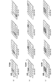
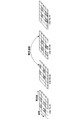
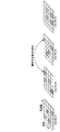
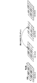
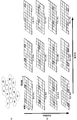
- (A)-(c) is a figure for demonstrating the orthogonalization method of CSI-RS in embodiment of this invention. It is a figure for demonstrating the non-orthogonalization of CSI-RS by shifting. It is a figure for demonstrating the non-orthogonalization of CSI-RS by hopping. It is a figure for demonstrating the non-orthogonalization of CSI-RS by scrambling.
- (A) is a figure which shows a cell structure
- (b) is a figure which shows the example of a combination of non-orthogonalization and orthogonalization. It is a figure which shows the radio
- the radio base station apparatus since the radio base station apparatus employs MIMO transmission using a plurality of transmission / reception antennas, transmission antennas in the same cell must be orthogonalized.
- the LTE system or LTE-A system is a system that repeats the frequency for each cell.
- In order to measure the reception quality in consideration of interference in the mobile terminal device at the cell edge basically, non-orthogonalization (random Should be).
- non-orthogonalization random Should be
- the essence of the present invention is to generate a channel quality measurement reference signal, perform non-orthogonal processing on the channel quality measurement reference signal so as to be non-orthogonal between at least some cells, and transmit signals.
- Channel quality measurement reference signals are orthogonalized, and downlink channel quality measurement reference signals are transmitted in consideration of orthogonalization between transmit antennas, orthogonalization between cells, and high-precision interference estimation. is there.
- CSI-RS channel quality measurement reference signal
- Examples of a method for orthogonalizing CSI-RS include time division multiplexing, frequency division multiplexing, and code division multiplexing methods shown in FIGS. These methods may be employed individually or two or more methods may be combined.
- FIG. 1 (a) is a diagram showing a case where CSI-RS is time division multiplexed (TDM).
- TDM time division multiplexed
- a plurality of CSI-RSs are multiplexed using different OFDM symbols, and data is punctured so that the CSI-RSs do not interfere with other data.
- the CSI-RS transmitted by the transmission antenna (or cell) # 1 is arranged in the innermost OFDM symbol in the second subcarrier from the left, and the second subcarrier from the left. Puncture other OFDM symbols on the carrier (OFDM symbols on which CSI-RS transmitted by other transmission antennas are multiplexed).
- the CSI-RS transmitted by the transmission antenna (or cell) # 2 is arranged in the second OFDM symbol from the back in the second subcarrier from the left, and another OFDM in the second subcarrier from the left Puncture symbols (OFDM symbols on which CSI-RS transmitted by other transmitting antennas are multiplexed).
- the CSI-RS transmitted by the transmitting antenna (or cell) # 3 is arranged in the third OFDM symbol from the back in the second subcarrier from the left, and another OFDM in the second subcarrier from the left Puncture symbols (OFDM symbols on which CSI-RS transmitted by other transmitting antennas are multiplexed).
- the CSI-RS to be transmitted by transmission antenna (or cell) # 4 is arranged in the frontmost OFDM symbol in the second subcarrier from the left, and another OFDM symbol in the second subcarrier from the left (OFDM symbol multiplexed with CSI-RS transmitted by other transmitting antenna) is punctured.
- the CSI-RS is orthogonalized between transmission antennas and does not interfere with other data.
- the puncture process is a desirable process and is not an essential process.
- FIG. 1B is a diagram illustrating a case where CSI-RS is frequency division multiplexed (FDM).
- FDM frequency division multiplexed
- a plurality of CSI-RSs are multiplexed using different subcarriers, and data is punctured so that the CSI-RSs do not interfere with other data.
- the CSI-RS transmitted by the transmission antenna (or cell) # 1 is arranged in the innermost OFDM symbol in the second subcarrier from the left, and the most in the other subcarriers.
- a back OFDM symbol an OFDM symbol in which CSI-RS transmitted by another transmitting antenna is multiplexed
- is punctured is punctured.
- the CSI-RS transmitted by the transmitting antenna (or cell) # 2 is arranged in the innermost OFDM symbol in the third subcarrier from the left, and the innermost OFDM symbol (others in other subcarriers) Puncture the CSI-RS multiplexed OFDM symbol) transmitted by the transmission antennas of the first and second transmission antennas.
- the CSI-RS to be transmitted by transmitting antenna (or cell) # 3 is arranged in the OFDM symbol from the back to the back in the fourth subcarrier from the left, and the backmost OFDM symbol in the other subcarrier (OFDM symbol multiplexed with CSI-RS transmitted by other transmitting antenna) is punctured.
- the CSI-RS to be transmitted by the transmitting antenna (or cell) # 4 is arranged in the innermost OFDM symbol in the fifth subcarrier from the left, and the innermost OFDM symbol (others in the other subcarriers) Puncture the CSI-RS multiplexed OFDM symbol) transmitted by the transmission antennas of the first and second transmission antennas.
- the CSI-RS is orthogonalized between transmission antennas and does not interfere with other data.
- the puncture process is a desirable process and is not an essential process.
- FIG. 1 (c) is a diagram showing a case where CSI-RS is code division multiplexed (CDM).
- code division multiplexing a plurality of CSI-RSs are arranged in the same OFDM symbol in the time / frequency domain, and are multiplexed using orthogonal codes between transmission antennas (or cells).
- the CSI-RS transmitted by transmitting antennas (or cells) # 1 to # 4 is divided into two OFDM symbols from the back on the second subcarrier from the left, and the third from the left.
- the subcarriers are arranged in four OFDM symbols including two OFDM symbols from the back, and are orthogonalized between transmitting antennas using orthogonal codes. In this case, other OFDM symbols are not punctured. Since these four OFDM symbols are orthogonalized by orthogonal codes, CSI-RS is orthogonalized between transmitting antennas.
- examples of the orthogonal code include a Walsh code.
- TDM, FDM, CDM orthogonalization methods
- CSI-RSs are arranged in different OFDM symbols and / or subcarriers, time-multiplexed and / or frequency-multiplexed, and transmission antennas (or cells) are orthogonalized with orthogonal codes.
- non-orthogonalizing (randomizing) CSI-RS between cells will be described.
- de-orthogonalizing CSI-RS non-orthogonal processing
- the shifting, hopping, and scrambling methods shown in FIGS. These methods may be employed individually or two or more methods may be combined.
- FIG. 2 is a diagram for explaining non-orthogonalization of CSI-RS by shifting. In shifting, each CSI-RS is mapped so as not to collide (do not interfere) in the time domain and the frequency domain.
- the CSI-RS transmitted in cell # 1 is arranged in the first and third OFDM symbols from the back in the second subcarrier from the left and the fourth subcarrier from the left.
- the CSI-RS transmitted in cell # 2 is arranged in the first and third OFDM symbols from the back in the third subcarrier from the left and the fifth subcarrier from the left.
- the CSI-RS transmitted in cell # 3 is arranged in the second and fourth OFDM symbols from the back in the second subcarrier from the left and the fourth subcarrier from the left.
- the CSI-RS transmitted in cell # 4 is arranged in the second and fourth OFDM symbols from the back in the third subcarrier from the left and the fifth subcarrier from the left. In this way, CSI-RS collisions between cells are avoided. In this case, the OFDM symbol is not punctured.
- this method is a method with high interference estimation accuracy.
- FIG. 3 is a diagram for explaining non-orthogonalization of CSI-RS by hopping.
- each CSI-RS is mapped randomly in the time domain and the frequency domain (Pseudo random).
- the CSI-RS transmitted in cell # 1 is the second and third OFDM symbols in the second subcarrier from the left, and the second from the back in the fourth subcarrier from the left.
- the OFDM symbol is arranged in the OFDM symbol and the frontmost OFDM symbol in the fifth subcarrier from the left.
- the CSI-RS transmitted in cell # 2 is divided into the frontmost OFDM symbol in the second subcarrier from the left, the backmost OFDM symbol in the third subcarrier from the left, and four from the left.
- the CSI-RS transmitted in cell # 3 is the second OFDM symbol from the back in the second subcarrier from the left, the third OFDM symbol from the back in the third subcarrier from the left, and the left To the last and frontmost OFDM symbols in the fifth subcarrier.
- the CSI-RS transmitted in cell # 4 is the second and first OFDM symbol from the back in the third subcarrier from the left, and the second and first from the back in the fifth subcarrier from the left. Arranged in the OFDM symbol before the count. In this way, the arrangement of CSI-RSs between cells is randomized. In this hopping, there is a case where there is a collision such as CSI-RS transmitted in cell # 2 in FIG. 3 and CSI-RS transmitted in cell # 3. Even in this case, the OFDM symbol is not punctured.
- mapping since CSI-RSs are randomly arranged, there are many arrangement patterns. For this reason, the number of cell repetitions can be increased compared to shifting.
- FIG. 4 is a diagram for explaining non-orthogonalization of CSI-RS by scrambling.
- each CSI-RS is arranged in the same OFDM symbol in the time / frequency domain, and is multiplied by a non-orthogonal code (scrambling code) that differs between cells.
- the CSI-RS transmitted in cell # 1 is transmitted in the innermost and third OFDM symbols in the second subcarrier from the left and the innermost and third in the fourth subcarrier from the left. And is made non-orthogonal between cells using different scrambling codes. In this case, other OFDM symbols are not punctured. Since these four OFDM symbols are randomized with different non-orthogonal codes, the CSI-RS becomes non-orthogonal between cells.
- Scrambling can be easily combined with shifting and hopping.
- shifting can be performed so that CSI-RSs are arranged in different OFDM symbols between cells, and different scrambling codes can be combined for each cell to combine shifting and scrambling.
- Hopping can be performed such that CSI-RS is arranged in a symbol, and scrambling codes different from each cell can be multiplied to combine hopping and scrambling, and CSI-RS is arranged in different OFDM symbols between cells.
- Shifting, hopping, and scrambling can be combined by shifting and hopping in this manner and multiplying by a different scrambling code for each cell.
- non-orthogonalization may be performed by shifting and hopping so that CSI-RSs are arranged in different OFDM symbols between cells.
- control signaling is required.
- shifting a shifting number (shifting identification information) representing a shifting pattern is signaled.
- hopping a hopping number (hopping identification information) representing a hopping pattern is signaled.
- scrambling a scrambling code is signaled.
- the scrambling code number, the shifting number, and the hopping number are referred to as non-orthogonalization control information.
- the orthogonalization control information includes the resource to be used and the orthogonal multiplexing number (orthogonal resource number (orthogonal resource identification information)).
- non-orthogonalized control information and orthogonalized control information may be notified as common control information or may be notified as individual control information. Further, the number of bits required for the control information can be reduced by associating with the cell ID.
- FIG. 5A is a diagram illustrating a cell configuration
- FIG. 5B is a diagram illustrating a combination example of non-orthogonalization and orthogonalization.
- the mode shown in FIG. 5B is a mode of combination of orthogonalization by FDM and non-orthogonalization by shifting.
- the present invention is not limited to this mode, and includes a mode in which non-orthogonalization is performed by orthogonalization or shifting using FDM and another orthogonalization method or other non-orthogonalization method.
- the cell configuration as shown in FIG. 5A is a cell configuration in which a cell group having an orthogonal multiplexing number of 3 is four. That is, this cell configuration is a cell configuration having cell groups 1 to 4 having an orthogonal multiplexing number of 3 (A to C). In such a cell configuration, while making orthogonal between some cells, non-orthogonal between other cells, and randomizing the entire interference.
- the cell groups (1 to 4) are made non-orthogonal, and the cells (A to C) in the cell group are made orthogonal. That is, between cells 1A, 1B, and 1C, a plurality of CSI-RSs are multiplexed using different subcarriers, and the CSI-RSs are orthogonalized by puncturing the data so that they do not interfere with other data. It has become. Similarly, by multiplexing a plurality of CSI-RSs using different subcarriers between the cells 2A, 2B, and 2C, and puncturing the data so that the CSI-RS does not interfere with other data. Orthogonalized.
- the CSI-RSs are mapped so as not to collide (do not interfere) in the time domain and the frequency domain.
- mapping between the cell 1B, the cell 2B, the cell 3B, and the cell 4B is performed so that the CSI-RSs do not collide (do not interfere) in the time domain and the frequency domain.
- the CSI-RSs are mapped between the cell 1C, the cell 2C, the cell 3C, and the cell 4C so that they do not collide (do not interfere) in the time domain and the frequency domain.
- the non-orthogonal processing is performed on the CSI-RS so that at least some of the cells are non-orthogonal to each other.
- the CSI-RSs of signals transmitted from the respective transmission antennas are orthogonalized.
- transmission modes that are orthogonalized between transmitting antennas and non-orthogonal between cells, or orthogonalized between transmitting antennas and non-orthogonalized between cells A transmission mode of a combination of / orthogonalization can be realized.
- a downlink channel quality measurement reference signal can be transmitted and received in consideration of orthogonalization between transmission antennas, orthogonalization between cells, and highly accurate interference estimation.
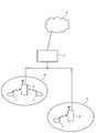
- FIG. 6 is a diagram showing a radio communication system having radio base station apparatuses and mobile terminal apparatuses according to the embodiment of the present invention.
- the wireless communication system is a system to which, for example, E-UTRA (Evolved UTRA and UTRAN) is applied.
- the radio communication system includes a radio base station apparatus (eNB: eNodeB) 2 (2 1 , 2 2 ... 2 l , l is an integer of l> 0) and a plurality of mobile terminal apparatuses communicating with the radio base station apparatus 2 (UE) 1 n (1 1 , 1 2 , 1 3 ,... 1 n , n is an integer of n> 0).
- the radio base station device 2 is connected to an upper station, for example, an access gateway device 3, and the access gateway device 3 is connected to the core network 4.
- the mobile terminal 1 n communicates with the radio base station apparatus 2 by E-UTRA in the cell 5 (5 1 , 5 2 ).
- the present embodiment shows two cells, the present invention can be similarly applied to three or more cells. Since each mobile terminal device (1 1 , 1 2 , 1 3 ,... 1 n ) has the same configuration, function, and state, the following description will be given as the mobile terminal device 1 n unless otherwise specified. To proceed.
- OFDM Orthogonal Frequency Division Multiple Access
- SC-FDMA Single Carrier Frequency Division Multiple Access
- OFDM is a multi-carrier transmission scheme that performs communication by dividing a frequency band into a plurality of narrow frequency bands (subcarriers) and mapping data to each subcarrier.
- SC-FDMA is a single carrier transmission scheme in which frequency bands are divided for each terminal, and a plurality of terminals use different frequency bands to reduce interference between terminals.
- a physical downlink shared channel (PDSCH) shared by each mobile terminal device 1 n and a physical downlink control channel (PDCCH) are used.
- the physical downlink control channel is also called a downlink L1 / L2 control channel.
- User data that is, a normal data signal is transmitted through the physical downlink shared channel.
- downlink scheduling information DL Scheduling Information
- acknowledgment information ACK / NACK
- uplink scheduling grant UL Scheduling Grant
- TPC command Transmission Power Control Command
- the downlink scheduling information includes, for example, the ID of a user who performs communication using a physical downlink shared channel, and information on the transport format of the user data, that is, data size, modulation scheme, retransmission control (HARQ: Hybrid ARQ). And downlink resource block allocation information.
- HARQ Hybrid ARQ
- the uplink scheduling grant includes, for example, the ID of a user who performs communication using the physical uplink shared channel, information on the transport format of the user data, that is, information on the data size and modulation scheme, This includes resource block allocation information, information related to uplink shared channel transmission power, and the like.
- the uplink resource block corresponds to a frequency resource and is also called a resource unit.
- the delivery confirmation information (ACK / NACK) is delivery confirmation information related to the uplink shared channel.
- the contents of the acknowledgment information are expressed by either an acknowledgment (ACK: Acknowledgement) indicating that the transmission signal has been properly received or a negative acknowledgment (NACK: Negative Acknowledgement) indicating that the transmission signal has not been properly received. Is done.
- a physical uplink shared channel (PUSCH) shared by each mobile terminal device 1 n and a physical uplink control channel (PUCCH) are used.
- User data that is, a normal data signal is transmitted through the physical uplink shared channel.
- the physical uplink control channel transmits downlink quality information and physical downlink shared channel delivery confirmation information to be used for downlink shared physical channel scheduling processing, adaptive modulation / demodulation, and encoding processing.
- a scheduling request for requesting uplink shared channel resource allocation (Scheduling Request), a release request for persistent scheduling (Release Request), etc. May be sent.
- the resource allocation of the uplink shared channel means that the radio base station can perform communication using the uplink shared channel in the subsequent subframe using the physical downlink control channel of a certain subframe. This means that the device notifies the mobile terminal device.
- the mobile terminal apparatus 1 n communicates with the optimal radio base station apparatus.
- the mobile terminal device 1 1, 1 2 communicates with the radio base station apparatus 2 1
- the mobile terminal device 1 3 is communicating with the radio base station apparatus 2 2.
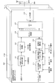
- FIG. 7 is a diagram showing a configuration of the radio base station apparatus according to the embodiment of the present invention. Although only the transmission unit is illustrated in FIG. 7, this radio base station apparatus naturally includes a reception unit that receives and processes an uplink signal.
- Each transmission signal generation unit 21 includes a shared channel signal generation unit 211 that generates a shared channel signal, a puncture processing unit 212 that punctures the shared channel signal, a CSI-RS sequence generation unit 213 that generates a CSI-RS sequence, A time / frequency mapping unit 214 that maps the CSI-RS to the time domain / frequency domain, a multiple RB selection unit 215 that selects a resource block (RB) for shifting and / or hopping the CSI-RS, and a shared channel signal Multiplexer 216 that multiplexes signals including CSI-RS, IFFT unit 217 that performs IFFT (Inverse Fast Fourier Transform) on the multiplexed signal, and CP addition that adds CP (Cyclic Prefix) to the signal after IFFT
- the main part is composed of the part 218.
- the shared channel signal generation unit 211 generates a shared channel signal (a signal transmitted by PDSCH) using downlink transmission data.
- Shared channel signal generation section 211 generates a shared channel signal based on the CSI measurement value measured by the radio base station apparatus using CSI-RS included in the uplink signal.
- the shared channel signal generation unit 211 outputs the generated shared channel signal to the puncture processing unit 212.
- the puncture processing unit 212 performs puncture processing on the generated shared channel signal. As shown in FIGS. 1 (a), 1 (b), and 5 (b), the puncturing process is performed between CSI-RS and shared channel signals (transmission data) arranged in RBs between transmission antennas and between some cells. ) To the shared channel signal.
- the puncture processing units 212 of the transmission signal generation units 21 # 1 to 21 # N have three CSI-RS orthogonal multiplexing numbers (A to C in the case of FIG. 5) included in the orthogonal resource information (orthogonal resource number). ) To puncture the shared channel signal.
- the puncturing processing unit 212 performs puncturing processing on the shared channel signal so that the CSI-RS and the shared channel signal (transmission data) do not interfere between cells or between transmission antennas based on the CSI-RS orthogonal multiplexing number.
- the puncture processing unit 212 outputs the shared channel signal after the puncture processing to the channel multiplexing unit 216.
- the CSI-RS sequence generation unit 213 generates a CSI-RS to be multiplexed on the RB.
- the CSI-RS sequence generator 213 scrambles the CSI-RS as a non-orthogonal process
- the CSI-RS is scrambled with a scrambling code based on the scrambling code number as shown in FIG. To do.
- the CSI-RS sequence generation unit 213 performs orthogonal code based on orthogonal code numbers between transmitting antennas and between cells to be orthogonalized, as shown in FIG. 1 (c). Then, the CSI-RS is orthogonalized using the orthogonal multiplexing number included in the orthogonal resource number.
- CSI-RS sequence generation section 213 outputs CSI-RS to time / frequency mapping section 214.
- the time / frequency mapping unit 214 maps the CSI-RS to the time domain / frequency domain in the RB.
- the time / frequency mapping unit 214 uses the number of orthogonal multiplexing included in the orthogonal resource number as shown in FIGS. 1 (a) and 1 (b).
- CSI-RS is orthogonalized.
- the time / frequency mapping unit 214 shifts and / or hops the CSI-RS based on the shifting number and / or the hopping number when performing shifting and / or hopping as the non-orthogonalization process.
- Time / frequency mapping section 214 outputs the mapped signal to multiplexed RB selection section 215.
- the multiplexing RB selection unit 215 selects which RB of the radio frame is multiplexed. Multiplex RB selection unit 215 selects where in the radio frame a signal including CSI-RS is multiplexed based on the shifting number and / or hopping number when shifting and / or hopping as non-orthogonalization processing. To do. Multiplex RB selection section 215 outputs an RB-selected signal including CSI-RS to channel multiplexing section 216.
- the channel multiplexing unit 216 performs channel multiplexing on the common channel signal and the signal including CSI-RS.
- Channel multiplexing section 216 outputs the channel-multiplexed signal to IFFT section 217.
- the IFFT unit 217 performs IFFT on the channel multiplexed signal and converts it into a time domain signal.
- IFFT section 217 outputs the signal after IFFT to CP adding section 218.
- CP adding section 218 adds a CP to the signal after IFFT.
- Signals to which CPs are added by the transmission signal generation units 21 # 1 to 21 # N are transmitted from the transmission antennas 22 # 1 to 22 # N to the mobile terminal apparatuses on the downlink (downlink physical shared channel), respectively.
- the time / frequency mapping unit 214 performs orthogonalization. Process.
- the CSI-RS sequence generation unit 213 performs the orthogonalization process.
- time / frequency mapping unit 214 and CSI-RS sequence generation The unit 213 performs orthogonalization processing.
- the time / frequency mapping unit 214 and the multiple RB selection unit 215 perform the non-orthogonal processing.
- the CSI-RS sequence generation unit 213 performs the non-orthogonal process.
- the CSI-RS sequence generation unit 213, the time / frequency mapping unit 214, and the multiplexed RB The selection unit 215 performs non-orthogonalization processing.
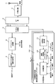
- FIG. 8 is a diagram showing a configuration of the mobile terminal apparatus according to the embodiment of the present invention.
- the mobile terminal apparatus shown in FIG. 8 includes a receiving antenna 11, a CP removing unit 12 that removes a CP from a received signal, an FFT unit 13 that performs an FFT (Fast Fourier Transform) on the CP removed signal, a shared channel signal, and a CSI.
- FFT Fast Fourier Transform
- a channel dividing unit 14 that divides a signal including RS, a depuncture processing unit 15 that depunctures a shared channel signal, a shared channel demodulation / decoding unit 16 that demodulates and decodes the depunctured shared channel signal, and a radio base CSI information generation units 17 # 1 to 17 # N that are provided corresponding to the transmission antennas of the station apparatus and obtain CSI measurement values from signals including CSI-RS are mainly configured.
- FIG. 8 only the CSI information generation unit 17 # 1 corresponding to the transmission antenna # 1 of the radio base station apparatus is illustrated in detail.
- Each of the CSI information generation units 17 # 1 to 17 # N demultiplexes the multiple RB extraction unit 171 that extracts RBs for shifting and / or hopping the CSI-RS, and the CSI-RS mapped in the time domain / frequency domain. It mainly comprises a time / frequency demapping unit 172 for mapping and a CSI measuring unit 173 for measuring CSI using the demapped CSI-RS.
- the signal transmitted from the radio base station apparatus on the downlink is received via the reception antenna 11 of the mobile terminal apparatus.
- CP removing section 12 removes the CP from the received signal.
- CP removing section 12 outputs the signal after CP removal to FFT section 13.
- the FFT unit 13 performs FFT on the signal after CP removal and converts it to a frequency domain signal.
- the FFT unit 13 outputs the signal after the FFT to the channel dividing unit 14.
- the channel division unit 14 divides the common channel signal and the signal including CSI-RS into channels.
- the channel division unit 14 outputs the channel-divided signal to the depuncture processing unit 15.
- the depuncture processing unit 15 performs depuncture processing on the shared channel signal that has been divided into channels.
- the depuncture processing unit 15 depunctures the shared channel signal based on the CSI-RS orthogonal multiplexing number (A to C in the case of FIG. 5) included in the orthogonal resource information (orthogonal resource number). .
- the depuncture processing unit 15 outputs the shared channel signal after the depuncture processing to the shared channel signal demodulation / decoding unit 16.
- the shared channel signal demodulation / decoding unit 16 demodulates and decodes the depunctured shared channel signal to obtain received data.
- the multiple RB extraction unit 171 extracts the RBs that have been shifted and / or hopped from the radio frame.
- Multiplex RB extraction section 171 extracts a signal including CSI-RS from a radio frame based on the shifting number and / or hopping number when shifting and / or hopping as non-orthogonalization processing.
- Multiplex RB extraction section 171 outputs an RB-extracted signal including CSI-RS to time / frequency demapping section 172.
- the time / frequency demapping unit 172 demaps the CSI-RS from the time domain / frequency domain in the RB.
- the time / frequency demapping unit 172 performs demapping using the number of orthogonal multiplexing included in the orthogonal resource number when time multiplexing and / or frequency multiplexing is adopted as the orthogonalization processing.
- the time / frequency demapping unit 172 demaps the CSI-RS based on the shifting number and / or the hopping number when the shifting and / or hopping is adopted as the non-orthogonalization process.
- the time / frequency demapping unit 172 outputs the demapped signal to the CSI measurement unit 173.
- the CSI measurement unit 173 measures channel quality using the demapped (extracted) CSI-RS, and outputs a CSI measurement value.
- CSI measurement section 173 descrambles and extracts CSI-RS with a scrambling code based on the scrambling code number.
- the CSI measurement unit 173 uses an orthogonal code based on an orthogonal code number and an orthogonal multiplexing number included in an orthogonal resource number between transmission antennas and between cells to be orthogonalized. Extract CSI-RS.
- the downlink signal includes control information for non-orthogonalization and / or control information for orthogonalization.
- the control information for non-orthogonalization includes a scrambling code number, a shifting number, and / or a hopping number.
- the orthogonalization control information includes an orthogonal resource number and an orthogonal code number including the resource to be used and the orthogonal multiplexing number.
- the resource to be used means cells (A to C) when described with reference to FIG. Therefore, the resource to be used is identification information indicating that the resource to be used is any one of A to C in the predetermined cell groups 1 to 4.
- the control information for non-orthogonalization and / or control information for orthogonalization may be notified from the radio base station apparatus to the mobile terminal apparatus through a broadcast channel (BCH) and transmitted as an L1 / L2 control signal. Or may be notified in an upper layer.
- BCH broadcast channel
- the scrambling code number which is control information for non-orthogonalization
- the shifting number and / or hopping number is sent to the time / frequency demapping unit 172 and the multiple RB extraction unit 171.
- the orthogonal resource number which is control information for orthogonalization
- the orthogonal code number which is the control information for orthogonalization is sent to the CSI measurement unit 173.
- the CSI-RS orthogonal multiplexing number is sent to the depuncture processing unit 15.
- a radio communication method in the radio base station apparatus and mobile terminal apparatus having the above configuration will be described.
- a CSI-RS is generated in a radio base station apparatus, and non-orthogonal processing is performed on the CSI-RS so that they are non-orthogonal between at least some cells.
- RS is orthogonalized between transmitting antennas and transmitted to the mobile terminal device together with the control information.
- the mobile terminal device receives the downlink signal including the control information and CSI-RS, and extracts the CSI-RS using the control information. Then, channel quality is measured using CSI-RS.
- the CSI-RS is multiplied by a scrambling code corresponding to the scrambling number, and a plurality of CSI-RSs are mapped so as to be multiplexed on different subcarriers between transmission antennas and between some cells.
- each CSI-RS is mapped between cells so as not to collide (do not interfere) in the time domain and the frequency domain to be non-orthogonalized (shifting).
- the shared channel signal is punctured so that CSI-RS and data do not interfere with each other between transmission antennas and between some cells.
- Such a shared channel signal and CSI-RS are channel-multiplexed, and this multiplexed signal is transmitted to the mobile terminal apparatus in the downlink.
- control information for non-orthogonalization and control information for orthogonalization are also transmitted to the mobile terminal apparatus in the downlink.
- the shared channel signal and the CSI-RS are divided, the shared channel signal is depunctured and demodulated and decoded, and the CSI-RS is demapped and extracted. Then, the channel quality is measured using CSI-RS to obtain a CSI measurement value.
- the CSI-RSs are non-orthogonally processed so as to be non-orthogonal between the cells, and the CSI-RS is transmitted between the transmission antennas and between some cells. By making orthogonal, it is possible to transmit a downlink channel quality measurement reference signal in consideration of orthogonalization between transmission antennas, orthogonalization between cells, and highly accurate interference estimation.
- the present invention is not limited to the above embodiment, and can be implemented with various modifications.
- the number of transmitting antennas and the number of cells are examples, and are not limited to this.
- the number of processing units and the processing procedure in the above description can be changed as appropriate without departing from the scope of the present invention.
- Each element shown in the figure represents a function, and each functional block may be realized by hardware or software. Other modifications can be made without departing from the scope of the present invention.
- the present invention is useful for an LTE-A system radio base station apparatus, mobile terminal apparatus, and radio communication method.
Landscapes
- Engineering & Computer Science (AREA)
- Signal Processing (AREA)
- Computer Networks & Wireless Communication (AREA)
- Power Engineering (AREA)
- Mobile Radio Communication Systems (AREA)
Abstract
Description
上述したように、無線基地局装置においては、複数の送受信アンテナを用いるMIMO伝送を採用しているので、同一セル内の送信アンテナ間は直交化する必要がある。LTEシステムやLTE-Aシステムは、1セル毎に周波数を繰り返すシステムであり、セル端にある移動端末装置において干渉を考慮した受信品質を測定するためには、基本的には非直交化(ランダム化)するべきである。しかしながら、マルチセル協調送信やセル間干渉調整の特性を改善させるためには、マルチセル協調送信やセル間干渉調整に関わるセル間では直交化することが望ましいと考えられる。
1)送信アンテナ間で直交化、セル間で非直交化
2)送信アンテナ間で直交化、セル間で非直交化/直交化の組み合わせ
ここで、2)の状態において、直交化するセルは、マルチセル協調送信やセル間干渉調整に関わるセルである。
下りリンクについては、各移動端末装置1nで共有される物理下りリンク共有チャネル(PDSCH:Physical Downlink Shared Channel)と、物理下りリンク制御チャネル(PDCCH:Physical Downlink Control Channel)とが用いられる。物理下りリンク制御チャネルは下りL1/L2制御チャネルとも呼ばれる。上記物理下りリンク共有チャネルにより、ユーザデータ、すなわち、通常のデータ信号が伝送される。また、物理下りリンク制御チャネルにより、下りスケジューリング情報(DL Scheduling Information)、送達確認情報(ACK/NACK)、上りスケジューリンググラント(UL Scheduling Grant)、TPCコマンド(Transmission Power Control Command)などが伝送される。下りスケジューリング情報には、例えば、物理下りリンク共有チャネルを用いて通信を行うユーザのIDや、そのユーザデータのトランスポートフォーマットの情報、すなわち、データサイズ、変調方式、再送制御(HARQ:Hybrid ARQ)に関する情報や、下りリンクのリソースブロックの割り当て情報などが含まれる。
本発明の無線通信方法においては、無線基地局装置において、CSI-RSを生成し、少なくとも一部のセル間で互いに非直交となるようにCSI-RSに対して非直交化処理し、CSI-RSを送信アンテナ間で直交化させ、制御情報と共に移動端末装置に送信し、移動端末装置において、制御情報及びCSI-RSを含む下りリンク信号を受信し、制御情報を用いてCSI-RSを抽出し、CSI-RSを用いてチャネル品質を測定する。
Claims (13)
- チャネル品質測定用参照信号を生成する生成手段と、少なくとも一部のセル間で互いに非直交となるように前記チャネル品質測定用参照信号に対して非直交化処理する非直交化手段と、を具備する送信信号生成手段を送信アンテナ分備えており、各送信信号生成手段で生成された送信信号の前記チャネル品質測定用参照信号を互いに直交化させて下り物理共有チャネルで送信することを特徴とする無線基地局装置。
- 前記チャネル品質測定用参照信号を一部のセル間で互いに直交化させて下り物理共有チャネルで送信することを特徴とする請求項1記載の無線基地局装置。
- マルチセル協調送信又は干渉調整に関わるセル間で直交化するように前記チャネル品質測定用参照信号に対して直交化処理することを特徴とする請求項1又は請求項2記載の無線基地局装置。
- 前記送信信号生成手段は、前記下り物理共有チャネルで送信するデータに対してパンクチャ処理するパンクチャ処理手段を有することを特徴とする請求項1記載の無線基地局装置。
- 前記非直交化処理は、スクランブリングと、シフティング及び/又はホッピングとにより行われることを特徴とする請求項1記載の無線基地局装置。
- 前記直交化処理は、時間分割多重、周波数分割多重、及び/又はコード分割多重で行われることを特徴とする請求項1記載の無線基地局装置。
- 非直交化用制御情報及びチャネル品質測定用参照信号を含む下りリンク信号を受信する受信手段と、前記非直交化用制御情報を用いて前記チャネル品質測定用参照信号を抽出し、前記チャネル品質測定用参照信号を用いてチャネル品質を測定する手段と、を具備することを特徴とする移動端末装置。
- 前記非直交化用制御情報はスクランブリングコード番号、シフティング番号及び/又はホッピング番号であることを特徴とする請求項7記載の移動端末装置。
- 前記下りリンク信号は、使用するリソース及び直交多重数を含む直交化用制御情報を含むことを特徴とする請求項7又は請求項8記載の移動端末装置。
- 下り物理共有チャネルで送信されたデータに対してデパンクチャ処理するデパンクチャ処理手段を有することを特徴とする請求項7記載の移動端末装置。
- 無線基地局装置において、チャネル品質測定用参照信号を生成する工程と、少なくとも一部のセル間で互いに非直交となるように前記チャネル品質測定用参照信号に対して非直交化処理する工程と、前記チャネル品質測定用参照信号を送信アンテナ間で直交化させ、非直交化用制御情報と共に移動端末装置に送信する工程と、前記移動端末装置において、前記非直交化用制御情報及び前記チャネル品質測定用参照信号を含む下りリンク信号を受信する工程と、前記非直交化用制御情報を用いて前記チャネル品質測定用参照信号を抽出し、前記チャネル品質測定用参照信号を用いてチャネル品質を測定する工程と、を具備することを特徴とする無線通信方法。
- 前記無線基地局装置において、マルチセル協調送信又は干渉調整に関わるセル間で直交化するように前記チャネル品質測定用参照信号に対して直交化処理することを特徴とする請求項11記載の無線通信方法。
- 前記無線基地局装置において、下り物理共有チャネルで送信するデータに対してパンクチャ処理し、前記移動端末装置において、前記下り物理共有チャネルで送信されたデータに対してデパンクチャ処理することを特徴とする請求項11又は請求項12記載の無線通信方法。
Priority Applications (9)
| Application Number | Priority Date | Filing Date | Title |
|---|---|---|---|
| EP21154277.4A EP3832942A1 (en) | 2010-01-05 | 2011-01-05 | Radio base station apparatus, mobile terminal device and wireless communication method |
| BR112012016562A BR112012016562A2 (pt) | 2010-01-05 | 2011-01-05 | aparelho de estação de base de rádio, dispositivo de terminal móvel e método de comunicação sem fio |
| US13/519,918 US9215026B2 (en) | 2010-01-05 | 2011-01-05 | Radio base station apparatus, mobile terminal device and wireless communication method |
| RU2012129726/07A RU2537978C2 (ru) | 2010-01-05 | 2011-01-05 | Базовая радиостанция, мобильный терминал и способ беспроводной связи |
| PH1/2012/501342A PH12012501342A1 (en) | 2010-01-05 | 2011-01-05 | Radio base station apparatus, mobile terminal device and wireless communication method |
| EP20110731792 EP2523376A1 (en) | 2010-01-05 | 2011-01-05 | Radio base station apparatuses, mobile terminal apparatuses and wireless communication method |
| KR1020127017346A KR101428736B1 (ko) | 2010-01-05 | 2011-01-05 | 무선기지국장치, 이동단말장치 및 무선통신방법 |
| AU2011204235A AU2011204235B2 (en) | 2010-01-05 | 2011-01-05 | Radio base station apparatus, mobile terminal device and wireless communication method |
| CN201180005447.2A CN102714564B (zh) | 2010-01-05 | 2011-01-05 | 无线基站装置、移动终端装置、无线通信方法和无线通信系统 |
Applications Claiming Priority (2)
| Application Number | Priority Date | Filing Date | Title |
|---|---|---|---|
| JP2010-000773 | 2010-01-05 | ||
| JP2010000773A JP5230663B2 (ja) | 2010-01-05 | 2010-01-05 | 無線基地局装置、移動端末装置及び無線通信方法 |
Publications (1)
| Publication Number | Publication Date |
|---|---|
| WO2011083794A1 true WO2011083794A1 (ja) | 2011-07-14 |
Family
ID=44305530
Family Applications (1)
| Application Number | Title | Priority Date | Filing Date |
|---|---|---|---|
| PCT/JP2011/050035 Ceased WO2011083794A1 (ja) | 2010-01-05 | 2011-01-05 | 無線基地局装置、移動端末装置及び無線通信方法 |
Country Status (10)
| Country | Link |
|---|---|
| US (1) | US9215026B2 (ja) |
| EP (3) | EP3832942A1 (ja) |
| JP (1) | JP5230663B2 (ja) |
| KR (1) | KR101428736B1 (ja) |
| CN (1) | CN102714564B (ja) |
| AU (1) | AU2011204235B2 (ja) |
| BR (1) | BR112012016562A2 (ja) |
| PH (1) | PH12012501342A1 (ja) |
| RU (1) | RU2537978C2 (ja) |
| WO (1) | WO2011083794A1 (ja) |
Cited By (2)
| Publication number | Priority date | Publication date | Assignee | Title |
|---|---|---|---|---|
| WO2013042883A1 (ko) * | 2011-09-20 | 2013-03-28 | 엘지전자 주식회사 | 무선 통신 시스템에서 링크 품질을 측정하는 방법 이를 위한 장치 |
| WO2013168542A1 (ja) * | 2012-05-10 | 2013-11-14 | 株式会社エヌ・ティ・ティ・ドコモ | 無線通信システム、基地局装置、ユーザ端末、及び無線通信方法 |
Families Citing this family (19)
| Publication number | Priority date | Publication date | Assignee | Title |
|---|---|---|---|---|
| US8559999B2 (en) * | 2006-05-29 | 2013-10-15 | Telefonaktiebolaget Lm Ericsson (Publ) | Channel quality prediction in HSDPA systems |
| RU2486687C2 (ru) * | 2010-02-17 | 2013-06-27 | ЗетТиИ (ЮЭсЭй) ИНК. | Способы и системы для csi-rs-передачи в системах по усовершенствованному стандарту lte |
| EP2489228B1 (en) | 2010-02-24 | 2017-04-05 | ZTE Corporation | Methods and systems for csi-rs resource allocation in lte-advance systems |
| CN102437987B (zh) | 2010-09-29 | 2015-09-16 | 中兴通讯股份有限公司 | 信道状态信息参考信号序列的生成和映射方法及装置 |
| CN103503332B (zh) * | 2011-05-04 | 2016-05-18 | Lg电子株式会社 | 在无线通信系统中发射/接收信道状态信息的方法和装置 |
| JP5864200B2 (ja) | 2011-05-20 | 2016-02-17 | 株式会社Nttドコモ | 受信装置、送信装置及び無線通信方法 |
| WO2013069345A1 (ja) * | 2011-11-07 | 2013-05-16 | 株式会社エヌ・ティ・ティ・ドコモ | 無線通信システム、基地局装置、移動端末装置、及び干渉測定方法 |
| JP5970170B2 (ja) * | 2011-11-07 | 2016-08-17 | 株式会社Nttドコモ | 無線通信システム、基地局装置、移動端末装置、及び干渉測定方法 |
| CN107181581B (zh) * | 2012-01-19 | 2021-06-01 | 太阳专利信托公司 | 用户设备和接收方法 |
| CN104253639B (zh) * | 2013-06-28 | 2017-12-01 | 华为技术有限公司 | 获取信道质量指示的方法及装置 |
| JP2015216449A (ja) * | 2014-05-08 | 2015-12-03 | ソニー株式会社 | 装置 |
| US10389477B2 (en) * | 2015-03-15 | 2019-08-20 | Qualcomm Incorporated | Devices and methods for facilitating a non-orthogonal underlay in wireless communications systems |
| EP3371906A4 (en) * | 2015-11-05 | 2019-06-26 | Nec Corporation | METHOD AND SYSTEM FOR DATA COMMUNICATION IN AN ADVANCED WIRELESS NETWORK |
| CN107370588B (zh) * | 2016-05-13 | 2021-04-20 | 华为技术有限公司 | 参考信号的发送方法及设备 |
| CN108282288B (zh) * | 2017-01-05 | 2021-01-15 | 华为技术有限公司 | 一种参考信号配置的方法、基站、用户设备和系统 |
| CN108347273B (zh) * | 2017-01-25 | 2021-06-29 | 华为技术有限公司 | 一种数据复用和数据解析方法、装置及系统 |
| US11310009B2 (en) * | 2017-05-05 | 2022-04-19 | Qualcomm Incorporated | Reference signal acquisition |
| GB2562117B (en) | 2017-05-05 | 2021-07-28 | Samsung Electronics Co Ltd | Phase tracking reference signal |
| WO2022246716A1 (en) * | 2021-05-27 | 2022-12-01 | Qualcomm Incorporated | Neural network assisted communication techniques |
Family Cites Families (9)
| Publication number | Priority date | Publication date | Assignee | Title |
|---|---|---|---|---|
| US5392287A (en) * | 1992-03-05 | 1995-02-21 | Qualcomm Incorporated | Apparatus and method for reducing power consumption in a mobile communications receiver |
| US7873710B2 (en) * | 2007-02-06 | 2011-01-18 | 5O9, Inc. | Contextual data communication platform |
| EP2176965B1 (en) * | 2007-07-16 | 2018-09-05 | Samsung Electronics Co., Ltd. | Apparatus and method for transmitting of channel quality indicator and acknowledgement signals in sc-fdma communication systems |
| JP2010000773A (ja) | 2007-09-28 | 2010-01-07 | Fujifilm Corp | フィルムの製造方法 |
| EP2454827B1 (en) * | 2009-06-19 | 2019-03-27 | BlackBerry Limited | Downlink reference signal for type ii relay |
| JP5198480B2 (ja) * | 2009-06-23 | 2013-05-15 | 株式会社エヌ・ティ・ティ・ドコモ | 無線基地局装置及び移動局装置、無線通信方法 |
| KR101237666B1 (ko) * | 2009-07-28 | 2013-02-26 | 엘지전자 주식회사 | 다중 입출력 통신 시스템에서 셀간 간섭을 제거하기 위한 기준신호 전송 방법 및 장치 |
| US20110244877A1 (en) * | 2009-10-08 | 2011-10-06 | Qualcomm Incorporated | Method and apparatus for using channel state information reference signal in wireless communication system |
| US20110317656A1 (en) * | 2009-12-23 | 2011-12-29 | Qualcomm Incorporated | Cluster-specific reference signals for communication systems with multiple transmission points |
-
2010
- 2010-01-05 JP JP2010000773A patent/JP5230663B2/ja not_active Expired - Fee Related
-
2011
- 2011-01-05 BR BR112012016562A patent/BR112012016562A2/pt not_active IP Right Cessation
- 2011-01-05 WO PCT/JP2011/050035 patent/WO2011083794A1/ja not_active Ceased
- 2011-01-05 PH PH1/2012/501342A patent/PH12012501342A1/en unknown
- 2011-01-05 EP EP21154277.4A patent/EP3832942A1/en active Pending
- 2011-01-05 AU AU2011204235A patent/AU2011204235B2/en not_active Ceased
- 2011-01-05 KR KR1020127017346A patent/KR101428736B1/ko not_active Expired - Fee Related
- 2011-01-05 EP EP20110731792 patent/EP2523376A1/en not_active Withdrawn
- 2011-01-05 EP EP15156298.0A patent/EP2890032A1/en not_active Withdrawn
- 2011-01-05 RU RU2012129726/07A patent/RU2537978C2/ru not_active IP Right Cessation
- 2011-01-05 CN CN201180005447.2A patent/CN102714564B/zh active Active
- 2011-01-05 US US13/519,918 patent/US9215026B2/en active Active
Non-Patent Citations (4)
| Title |
|---|
| ATSUSHI NAGATE ET AL.: "A Study on Resource Allocation Method Considering Inter-Sector Cooperative Transmission", PROCEEDINGS OF THE SOCIETY CONFERENCE OF IEICE, 2009 NEN_TSUSHIN (1), 1 September 2009 (2009-09-01), pages 394, XP008163833 * |
| HUAWEI: "Further design and evaluation on CSI-RS for LTE-A", 3GPP TSG RAN WG1 MEETING #59 R1- 094704, 9 November 2009 (2009-11-09), XP050389104 * |
| NTT DOCOMO: "CSI-RS Inter-cell Design Aspects", 3GPP TSG RAN WG1 MEETING #59BIS RL-100498, 18 January 2010 (2010-01-18), XP050418133 * |
| QUALCOMM EUROPE: "Details of CSI-RS", 3GPP TSG RAN WG1 #59 R1-094867, 9 November 2009 (2009-11-09), XP050597855 * |
Cited By (6)
| Publication number | Priority date | Publication date | Assignee | Title |
|---|---|---|---|---|
| WO2013042883A1 (ko) * | 2011-09-20 | 2013-03-28 | 엘지전자 주식회사 | 무선 통신 시스템에서 링크 품질을 측정하는 방법 이를 위한 장치 |
| US9648510B2 (en) | 2011-09-20 | 2017-05-09 | Lg Electronics Inc. | Method for measuring link quality in a wireless communication system and apparatus therefor |
| KR101907019B1 (ko) | 2011-09-20 | 2018-12-07 | 엘지전자 주식회사 | 무선 통신 시스템에서 링크 품질을 측정하는 방법 이를 위한 장치 |
| WO2013168542A1 (ja) * | 2012-05-10 | 2013-11-14 | 株式会社エヌ・ティ・ティ・ドコモ | 無線通信システム、基地局装置、ユーザ端末、及び無線通信方法 |
| JP2013236330A (ja) * | 2012-05-10 | 2013-11-21 | Ntt Docomo Inc | 無線通信システム、基地局装置、ユーザ端末、及び無線通信方法 |
| US9419760B2 (en) | 2012-05-10 | 2016-08-16 | Ntt Docomo, Inc. | Radio communication system, base station apparatus, user terminal, and radio communication method |
Also Published As
| Publication number | Publication date |
|---|---|
| KR20120101106A (ko) | 2012-09-12 |
| BR112012016562A2 (pt) | 2016-04-26 |
| EP3832942A1 (en) | 2021-06-09 |
| PH12012501342A1 (en) | 2012-12-17 |
| EP2523376A1 (en) | 2012-11-14 |
| JP5230663B2 (ja) | 2013-07-10 |
| AU2011204235B2 (en) | 2014-05-15 |
| US20120300653A1 (en) | 2012-11-29 |
| AU2011204235A1 (en) | 2012-07-26 |
| RU2537978C2 (ru) | 2015-01-10 |
| US9215026B2 (en) | 2015-12-15 |
| CN102714564B (zh) | 2016-03-23 |
| EP2890032A1 (en) | 2015-07-01 |
| RU2012129726A (ru) | 2014-02-20 |
| KR101428736B1 (ko) | 2014-08-11 |
| CN102714564A (zh) | 2012-10-03 |
| JP2011142406A (ja) | 2011-07-21 |
Similar Documents
| Publication | Publication Date | Title |
|---|---|---|
| JP5230663B2 (ja) | 無線基地局装置、移動端末装置及び無線通信方法 | |
| EP2827667B1 (en) | Terminal device, base station device, and integrated circuit | |
| EP2747320B1 (en) | Method and apparatus for transmitting uplink reference signal in wireless communication system | |
| JP5554799B2 (ja) | 無線基地局装置、ユーザ端末、無線通信システム及び無線通信方法 | |
| CN102714563B (zh) | 无线基站装置、移动终端装置、无线通信方法及无线通信系统 | |
| EP2779493A1 (en) | Wireless communication system, base station, mobile equipment, and interference measurement method | |
| US20140376484A1 (en) | Method and apparatus for transmitting uplink signal in wireless communication system | |
| US9438396B2 (en) | Radio communication system, mobile terminal apparatus, radio base station apparatus and radio communication method | |
| JP5970170B2 (ja) | 無線通信システム、基地局装置、移動端末装置、及び干渉測定方法 | |
| WO2013069538A1 (ja) | 無線通信システム、無線基地局装置、ユーザ端末及び無線通信方法 | |
| WO2014041888A1 (ja) | 無線通信システム、基地局装置、移動端末装置、及び干渉測定方法 | |
| EP2779740A1 (en) | Wireless communication system, wireless base station, user equipment, and wireless communication method | |
| US9780932B2 (en) | Radio communication system, mobile terminal apparatus, radio base station apparatus and radio communication method | |
| JP5781139B2 (ja) | 無線基地局装置、移動端末装置、無線通信システム及び無線通信方法 | |
| JP5599481B2 (ja) | 無線基地局装置、移動端末装置、無線通信方法及び無線通信システム |
Legal Events
| Date | Code | Title | Description |
|---|---|---|---|
| WWE | Wipo information: entry into national phase |
Ref document number: 201180005447.2 Country of ref document: CN |
|
| 121 | Ep: the epo has been informed by wipo that ep was designated in this application |
Ref document number: 11731792 Country of ref document: EP Kind code of ref document: A1 |
|
| WWE | Wipo information: entry into national phase |
Ref document number: 12012501342 Country of ref document: PH |
|
| ENP | Entry into the national phase |
Ref document number: 20127017346 Country of ref document: KR Kind code of ref document: A |
|
| WWE | Wipo information: entry into national phase |
Ref document number: 2011204235 Country of ref document: AU |
|
| NENP | Non-entry into the national phase |
Ref country code: DE |
|
| WWE | Wipo information: entry into national phase |
Ref document number: 6400/CHENP/2012 Country of ref document: IN |
|
| ENP | Entry into the national phase |
Ref document number: 2011204235 Country of ref document: AU Date of ref document: 20110105 Kind code of ref document: A |
|
| WWE | Wipo information: entry into national phase |
Ref document number: 2011731792 Country of ref document: EP |
|
| WWE | Wipo information: entry into national phase |
Ref document number: 2012129726 Country of ref document: RU |
|
| WWE | Wipo information: entry into national phase |
Ref document number: 13519918 Country of ref document: US |
|
| REG | Reference to national code |
Ref country code: BR Ref legal event code: B01A Ref document number: 112012016562 Country of ref document: BR |
|
| ENP | Entry into the national phase |
Ref document number: 112012016562 Country of ref document: BR Kind code of ref document: A2 Effective date: 20120704 |