WO2011086602A1 - 接合部材の製造方法及び摩擦攪拌接合装置 - Google Patents
接合部材の製造方法及び摩擦攪拌接合装置 Download PDFInfo
- Publication number
- WO2011086602A1 WO2011086602A1 PCT/JP2010/000204 JP2010000204W WO2011086602A1 WO 2011086602 A1 WO2011086602 A1 WO 2011086602A1 JP 2010000204 W JP2010000204 W JP 2010000204W WO 2011086602 A1 WO2011086602 A1 WO 2011086602A1
- Authority
- WO
- WIPO (PCT)
- Prior art keywords
- probe
- end point
- point position
- joining
- joined
- Prior art date
- Legal status (The legal status is an assumption and is not a legal conclusion. Google has not performed a legal analysis and makes no representation as to the accuracy of the status listed.)
- Ceased
Links
Images
Classifications
-
- B—PERFORMING OPERATIONS; TRANSPORTING
- B23—MACHINE TOOLS; METAL-WORKING NOT OTHERWISE PROVIDED FOR
- B23K—SOLDERING OR UNSOLDERING; WELDING; CLADDING OR PLATING BY SOLDERING OR WELDING; CUTTING BY APPLYING HEAT LOCALLY, e.g. FLAME CUTTING; WORKING BY LASER BEAM
- B23K20/00—Non-electric welding by applying impact or other pressure, with or without the application of heat, e.g. cladding or plating
- B23K20/12—Non-electric welding by applying impact or other pressure, with or without the application of heat, e.g. cladding or plating the heat being generated by friction; Friction welding
- B23K20/122—Non-electric welding by applying impact or other pressure, with or without the application of heat, e.g. cladding or plating the heat being generated by friction; Friction welding using a non-consumable tool, e.g. friction stir welding
- B23K20/123—Controlling or monitoring the welding process
- B23K20/124—Controlling or monitoring the welding process at the beginning or at the end of a weld
-
- B—PERFORMING OPERATIONS; TRANSPORTING
- B23—MACHINE TOOLS; METAL-WORKING NOT OTHERWISE PROVIDED FOR
- B23K—SOLDERING OR UNSOLDERING; WELDING; CLADDING OR PLATING BY SOLDERING OR WELDING; CUTTING BY APPLYING HEAT LOCALLY, e.g. FLAME CUTTING; WORKING BY LASER BEAM
- B23K20/00—Non-electric welding by applying impact or other pressure, with or without the application of heat, e.g. cladding or plating
- B23K20/12—Non-electric welding by applying impact or other pressure, with or without the application of heat, e.g. cladding or plating the heat being generated by friction; Friction welding
- B23K20/122—Non-electric welding by applying impact or other pressure, with or without the application of heat, e.g. cladding or plating the heat being generated by friction; Friction welding using a non-consumable tool, e.g. friction stir welding
- B23K20/123—Controlling or monitoring the welding process
-
- B—PERFORMING OPERATIONS; TRANSPORTING
- B23—MACHINE TOOLS; METAL-WORKING NOT OTHERWISE PROVIDED FOR
- B23K—SOLDERING OR UNSOLDERING; WELDING; CLADDING OR PLATING BY SOLDERING OR WELDING; CUTTING BY APPLYING HEAT LOCALLY, e.g. FLAME CUTTING; WORKING BY LASER BEAM
- B23K31/00—Processes relevant to this subclass, specially adapted for particular articles or purposes, but not covered by any single one of main groups B23K1/00 - B23K28/00
- B23K31/003—Processes relevant to this subclass, specially adapted for particular articles or purposes, but not covered by any single one of main groups B23K1/00 - B23K28/00 relating to controlling of welding distortion
-
- B—PERFORMING OPERATIONS; TRANSPORTING
- B23—MACHINE TOOLS; METAL-WORKING NOT OTHERWISE PROVIDED FOR
- B23K—SOLDERING OR UNSOLDERING; WELDING; CLADDING OR PLATING BY SOLDERING OR WELDING; CUTTING BY APPLYING HEAT LOCALLY, e.g. FLAME CUTTING; WORKING BY LASER BEAM
- B23K37/00—Auxiliary devices or processes, not specially adapted for a procedure covered by only one of the other main groups of this subclass
- B23K37/02—Carriages for supporting the welding or cutting element
- B23K37/0258—Electric supply or control circuits therefor
-
- B—PERFORMING OPERATIONS; TRANSPORTING
- B23—MACHINE TOOLS; METAL-WORKING NOT OTHERWISE PROVIDED FOR
- B23K—SOLDERING OR UNSOLDERING; WELDING; CLADDING OR PLATING BY SOLDERING OR WELDING; CUTTING BY APPLYING HEAT LOCALLY, e.g. FLAME CUTTING; WORKING BY LASER BEAM
- B23K37/00—Auxiliary devices or processes, not specially adapted for a procedure covered by only one of the other main groups of this subclass
- B23K37/02—Carriages for supporting the welding or cutting element
- B23K37/0282—Carriages forming part of a welding unit
Definitions
- the present invention relates to a method for manufacturing a joining member by friction stir welding two members to be joined by rotating a probe, and a friction stir welding apparatus.
- This friction stir welding method has the advantage that the joined parts are not melted by high heat during joining, and therefore, the members to be joined are less likely to be distorted or deformed.
- Patent Documents 1 and 2 As a technique for improving the joining reliability of this friction stir welding, there are techniques described in Patent Documents 1 and 2, for example.
- Patent Documents 1 and 2 can surely improve the bonding reliability, the bonding start point in the bonding portion and the probe start point position when forming the bonding start point, or the bonding There is a problem that there is a large amount of the oxide film remaining at the interface of the member to be joined between the end point and the probe end point position, and there is a problem that the reliability of joining remains uneasy.
- the present invention aims to provide a method for manufacturing a joining member and a friction stir welding apparatus capable of improving the joining reliability by paying attention to such problems of the prior art.
- the invention relating to the manufacturing method of the joining member for solving the above problems is
- a rotating probe is put into a joint portion of two members to be joined that are in contact with each other, and the joint member is manufactured by continuously friction stir welding the joint portion.
- the probe is moved from the probe start position, which is the position of the probe when forming the joining start point in the joined member, to the probe end position, which is the position of the probe when forming the joining end point in the joined member.
- the dwell process is performed at the probe start point position or the probe end point position, plastic flow around the probe start point position or the probe end point position advances, and friction stir welding is promoted.
- the oxide film at the interface of each member to be joined around the probe start point position or the probe end point position is significantly reduced, and the joining reliability around these positions can be further improved.
- the predetermined time is a time during which the distance corresponding to the outer diameter of the tip surface of the tool provided with the probe can be moved at a moving speed when the probe is moved from the probe start point position to the probe end point position. It may be the above. As described above, when the predetermined time is determined, the plastic flow around the probe start point position or the probe end point position can be plastically flowed at the same level or more as the plastic flow at the intermediate portion between the probe start point position and the probe end point position. it can.
- this end point position avoidance step is performed, the probe extraction hole formed at the probe extraction position moves away from the bonding end point, and the bonding reliability in the vicinity of the bonding end point can be improved.
- the probe extraction position may include an extraction position retention step of rotating the probe for a predetermined time.
- this drawing position retention step is performed, plastic flow around the probe drawing position is promoted, and the probe drawing hole formed at the probe drawing position becomes a smooth shape, and stress concentration on the probe drawing hole is alleviated. Can do.
- a predetermined distance may be returned from the probe end point position to the probe start point position side in the joint joining portion, and the position after the predetermined distance may be set as the probe extraction position.
- the probe at the probe end point position may be slightly pushed toward the bonded member side, and then the probe may be moved to the probe withdrawal position while maintaining the pushing amount of the probe.
- the invention relating to the friction stir welding apparatus for solving the above problems is
- a friction stir welding apparatus that puts a rotating probe into a joint planned portion of two members to be joined that are in contact with each other, and friction stir welds the joint planned portion
- a tool provided with the probe at the tip is mountable, and includes a mechanism unit that rotates and moves the mounted tool, and a control unit that controls the operation of the mechanism unit
- the control unit includes a probe start point position that is a position of the probe when forming a joining start point in the member to be joined and a probe end point that is a position of the probe when forming a joining end point in the member to be joined.
- An input / output means for receiving parameters including a position, a dwell time for rotating the tool at at least one of the probe start position and the probe end position, and the control received by the input / output means According to the parameter, the mechanism unit rotates the probe to the probe start point position, rotates the probe to the probe end point position, and at least one of the probe start point position and the probe end point position. Control execution means for executing the staying process for the time at the position.
- the dwell process is executed at the probe start point position or the probe end point position, plastic flow around the probe start point position or the probe end point position advances, and friction stir welding is promoted.
- the oxide film at the interface of each member to be joined around the probe start point position or the probe end point position is significantly reduced, and the joining reliability around these positions can be further improved.
- the input / output means, as the parameter, the moving speed when moving the probe from the probe start point position to the probe end point position, the outer diameter of the tip surface of the tool provided with the probe,
- the input time of the staying process is less than the time during which the diameter of the tip surface can be moved at the moving speed, the acceptance of the time is refused or a warning that the time is not appropriate is issued. May be. In this way, by issuing a warning or the like, the retention process time can be set to an appropriate time.
- the input / output means of the control unit receives a probe extraction position for extracting the probe from the member to be joined and a time for the extraction position retention process for rotating the tool at the probe extraction position, and executes control of the control unit.
- the means may cause the mechanism portion to execute the extraction position retention process for the time at the probe extraction position.
- plastic flow around the probe start point position or the probe end point position proceeds, so the oxide film at the interface of each member to be joined around these positions is significantly reduced, and the bonding reliability around these positions is increased.
- the sex can be increased.
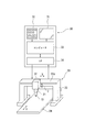
- the friction stir welding apparatus is equipped with a tool 10 having a probe provided at the tip, and a mechanism 20 that rotates and moves the tool 10, and controls the mechanism 20. And a control unit 30.
- the mechanism unit 20 includes a main shaft 21 on which the tool 10 is mounted, a main shaft holding head 22 that holds the main shaft 21 and a Y-direction guide 23 y that extends in the horizontal direction (Y direction). And a surface plate 24 on which the member to be joined is attached to the upper surface and moves the member to be joined in the X direction that is horizontal and perpendicular to the Y direction.
- the mechanism unit 20 further includes a hydraulic circuit, a power supply circuit, various sensors, and the like that drive each mechanism of the mechanism unit 20.
- the spindle holding head 22 holds a spindle 21 and rotates the spindle 21 (not shown), a Z-direction moving mechanism (not shown) that moves the spindle 21 in the vertical direction (Z direction), and a portal type.
- a Y-direction moving mechanism (not shown) that moves the main shaft 21 in the Y direction along the Y-direction guide 23y provided on the frame 23 is provided.
- the control unit 30 sends a control signal generated by the display 31, the input key 32, the computer 33, and the computer 33 to the hydraulic circuit and the power supply circuit of the mechanism unit 20, while receiving signals from various sensors of the mechanism unit 20.
- the input / output unit includes the display 31, the input key 32, and the computer 33
- the control execution unit includes the computer 33 and the interface 34.
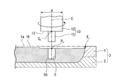
- the tool 10 includes a shoulder portion 12 having a circular shoulder surface 13 and a probe 11 protruding from the shoulder surface 13 of the shoulder portion 12. That is, the shoulder surface 13 forms the tip surface of the tool on which the probe 11 is provided.
- the shoulder portion 12 and the probe 11 rotate together, but they do not necessarily rotate together.
- the operator superimposes two members 1 and 2 on the surface plate 24 of the friction stir welding apparatus shown in FIG. 12, and fixes them using a jig or the like. Subsequently, the operator performs initial setting of the friction stir welding apparatus. In this initial setting, the origin of the tool 10 is adjusted and various parameters are input.
- the computer 33 causes the display 31 to display a parameter input screen.
- a probe length input field 31a As shown in FIG. 13, a probe length input field 31a, a probe diameter input field 31b, a shoulder diameter input field 31c which is the outer diameter of the shoulder surface, and a member to be joined are joined.
- the input field 31d of the probe start point position which is the position of the probe when forming the start point
- the input field 31e of the probe end point position which is the position of the probe when forming the joining end point on the member to be joined
- a certain probe extraction position input field 31f, a tool rotation speed input field 31g, a tool movement speed input field 31h, a dwell time input field 31i at the probe start point position, and a dwell process at the probe end point position At least a time input column 31j and a stay processing time input column 31k at the probe extraction position are displayed.
- the operator operates the input key 32 (FIG. 12) to input a numerical value in each of the parameter input fields described above. However, it is necessary to enter the residence time input field 31i at the probe start position, the residence time entry field 31j at the probe end position, and the residence time entry field 31k at the probe withdrawal position. However, in the following, it is assumed that the residence time is input to all the input fields 31i, 31j, 31k. Further, here, the positions inputted as probe positions such as the probe start point position, probe end point position, probe withdrawal position, etc. are the positions of the intersection Cp between the center line C of the probe 11 and the shoulder surface 13 as shown in FIG. It is. The position input as the probe position may be on the center line C of the probe 11 and the position of the tip of the probe 11.
- the staying process is executed at any of the probe start point position, the probe end point position, and the probe extraction position.
- the staying process is a process of accelerating the friction stirring of the member to be joined around the corresponding position without rotating the probe 11 while rotating the probe 11 at any of the above positions.
- the residence time is the time for which this residence process is performed.
- control unit 30 (FIG. 12) of the friction stir welding apparatus operates the mechanism unit 20 to start joining of the two members to be joined by friction stir welding.
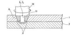
- the friction stir welding apparatus moves the probe 11 to the parameter start position Sp input by the parameter input process while rotating the probe 11. That is, the friction stir welding apparatus executes a process of inserting the probe 11 into the member to be joined.
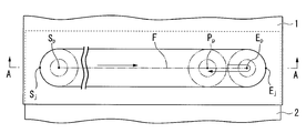
- FIG. 1 and FIGS. 2 to 8 used in the following description all show the state of the cross section along the line AA in FIG.
- the probe 11 is gradually inserted into the member 1 to be joined.
- the rotating probe 11 and the shoulder surface 13 come into contact with the member 1 to be bonded, frictional heat is generated between them, and the members 1 and 2 around the probe 11 plastically flow due to this frictional heat, and plasticity is generated.
- a flow region (or dynamic recrystallization region) A0 is formed.
- the probe start point Sp is used as a reference.
- the bonding strength in this portion becomes low.
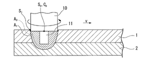
- the probe 11 immediately after the probe 11 reaches the probe start point Sp, the probe 11 is not moved to the probe end point Ep, but is rotated at the probe start point Sp for a predetermined time. A staying process that does not move is performed.
- the shoulder diameter d (FIG. 8), which is the outer diameter of the shoulder surface 13 input in the parameter input process, is moved at the tool moving speed v similarly input in the parameter input process. It is preferable that it is more than the time which takes. Specifically, although it depends on the tool moving speed or the like, for example, it is preferably 4 seconds or more.
- the friction stir time is (shoulder diameter) / (probe moving speed) in the intermediate portion between the probe start point Sp and the probe end point Ep within the planned joining portion. Therefore, in the present embodiment, the dwell time is set in order to ensure a friction stir time equal to or greater than that of the above-described intermediate portion even at the probe start point position Sp and the probe end point position Ep.
- the computer 33 determines that the input shoulder diameter d is less than the time required for moving at the previously input tool movement speed v, the computer 33 accepts the input residence time. Or flashes in the input fields 31i and 31j (FIG. 13) displayed on the display 31 to warn that the residence time is not appropriate.
- the tool 10 starts moving at the tool moving speed v toward the probe end point position Ep, and the main joining process is started.
- a point on the boundary between the plastic flow regions A 1 and A 2 after the dwell time ends and on the side opposite to the tool movement direction is the welding start point Sj.
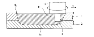
- the dwell process is executed at the probe end point Ep as well as the probe start point Sp.
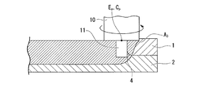
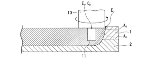
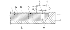
- the tool 10 slightly advances to the tip side of the probe 11 as shown in FIG. That is, in the tool 10, the probe 11 is slightly pushed into the bonded member 1. Then, the tool 10 starts moving at the tool moving speed toward the probe pulling position Pp.
- the probe extraction position Pp exists on the movement trajectory F of the probe 11 from the probe start point position Sp to the probe end point position Ep as shown in FIG.
- the level of the surface 1 b of the member 1 to be joined is higher than the level of the surface 1 a before the friction stir welding, in other words, the direction in which the probe 11 extends. It slightly changes in the thickness direction of the joining member 1. That is, when the friction stir welding is performed, the surface 1a of the member 1 to be joined sinks slightly.
- the shoulder surface 13 of the tool 10 is not moved unless the tool 10 is moved slightly in the direction in which the probe 11 extends at the probe end position Ep.
- the new surface 1b of the member 1 to be bonded is not sufficiently in contact, and frictional heat is not generated between the shoulder surface 13 and the new surface 1b of the member 1 to be bonded. Therefore, in this embodiment, when the dwell time at the probe end point Ep ends, the tool 10 is slightly moved in the direction in which the probe 11 extends, and the shoulder surface 13 of the tool 10 becomes a new surface of the member 1 to be joined. It is in sufficient contact with 1b.
- the probe position when the probe 11 moves in the extending direction is the same as the probe extraction position Pp in the direction in which the probe 11 extends. Therefore, the computer 33 (FIG. 12) of the friction stir welding apparatus obtains the distance t between the probe end point Ep and the probe withdrawal position Pp in the direction in which the probe 11 extends, and this distance t is calculated by the probe 11. The amount of movement in the extending direction.
- the tool 10 is slightly pushed into the bonded member 1 at the probe end point Ep, and then starts to move toward the probe extraction position Pp at the tool moving speed v as described above.
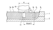
- the movement distance of the tool 10, that is, the distance D between the probe end point Ep and the probe extraction position Pp in the tool movement direction is half of the shoulder diameter d, that is, the shoulder radius d / 2 or more.
- the shoulder diameter is preferably d.
- the tool 10 in the end point position avoidance step, after the dwelling step at the probe end point position Ep is completed, the tool 10 is slightly pushed into the joined member 1 at the probe end point position Ep to the probe extraction position Pp. It is a process of moving. As shown in FIG. 7, the plastic flow region A 5 generated at the end point of the end point position avoiding step is more than the plastic flow region A 4 generated at the start point of the end point position avoiding step. 2 slightly spreads in the thickness direction. This is because the tool 10 is slightly pushed into the member 1 at the start of the end point position avoidance step.
- the staying process is also executed here. Since the probe 11 has already passed once and the friction stir welding has been performed once around the probe 11 at the probe extraction position Pp, as in the probe start point Sp and the probe end point Ep, No oxide film remains on the interface between the members 1 and 2.
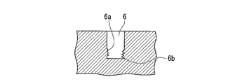
- the probe extraction hole 6 is inserted into the groove formed in the groove formed on the outer peripheral surface of the probe.
- the remainder 6a of the member remains on the inner peripheral surface of the probe extraction hole 6, and the corner shape between the tip end surface of the probe and the peripheral surface of the probe remains, and the inner peripheral surface of the probe extraction hole 6 is rough, and the probe extraction A corner 6b between the inner peripheral surface and the bottom surface of the hole 6 is also sharpened.
- the plastic fluidity of the member to be joined around the probe is not sufficient.
- the inner peripheral surface of the probe extraction hole 6 is roughened or the corner 6b between the inner peripheral surface and the bottom surface becomes sharp, stress is concentrated on the sharp corner or the like.
- the staying process is executed even at the probe extraction position Pp, and the plastic fluidity of the member to be joined around the probe 11 at the probe extraction position Pp is enhanced.
- the inner peripheral surface of the probe pulling hole 5 becomes smooth as shown in FIG.
- the corner 5b between the inner peripheral surface and the bottom surface is rounded. This is because the plastic fluidity of the member to be joined around the probe 11 has increased, and the residue of the member to be joined that has entered into the groove formed on the outer peripheral surface of the probe remains in the probe extraction hole 5 in the probe 11 extraction process. This is because it flows down along the peripheral surface.
- the staying time for example, half of the shoulder diameter d input by the parameter input process, that is, the shoulder radius d / 2, the tool movement input by the parameter input process. It is preferable that it is more than the time taken when moving at a speed. Specifically, although it depends on the tool moving speed or the like, for example, it is preferably 2 seconds or more.
- the dwell time when the dwell time is input to the dwell time input field 31k at the probe extraction position Pp in the parameter input process, the dwell time is half the d / 2 of the previously input shoulder diameter. If the computer 33 (FIG. 12) determines that it is less than the time required for moving at the tool movement speed input in, the computer 33 does not accept the input dwell time or is displayed on the display 31. The input field 31k is flashed to warn that the residence time is not appropriate.
- the bonding between the bonded member 1 and the bonded member 2 is completed, and the bonded member 3 is generated.
- the probe 11 is not pulled out at the probe end point Ep, but is pulled out from the probe end point Ep, so that no probe pull-out hole exists near the joining end point Ej. .
- it is possible to improve the bonding reliability in the vicinity of the bonding end point Ej.
- the staying process is also performed at the probe extraction position Pp, the plastic fluidity at the probe extraction position Pp is improved, and the inner surface of the probe extraction hole 5 is smooth and has no sharp corners. Stress concentration on the drawing hole 5 can be reduced.
- the staying process is executed at both the probe start point position Sp and the probe end point position Ep.
- the present invention is not limited to this, and is executed only at one of the positions. May be. For example, if a large load is not applied in the vicinity of the joining start point Sj and there is no need to increase the joining strength in the vicinity of the joining start point Sj, the staying process at the probe start point position Sp does not have to be performed.
- the staying process is performed even at the probe pulling position Pp. However, if it is not necessary to increase the bonding reliability in the vicinity of the probe pulling position Pp, the staying process at the probe pulling position Pp is performed. Need not be executed.
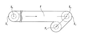
- the probe extraction position Pp is set on the movement trajectory F of the probe 11 from the probe start point position Sp to the probe end point position Ep. Is not required to be set on the movement trajectory F of the probe 11. For example, as shown in FIG. 11, the probe extraction position Pp may be set outside the movement trajectory F of the probe 11.
- the present invention is applied to the overlap bonding of two members to be bonded, but the present invention is not limited to this, for example, butt bonding of two members to be bonded.
- the present invention may be applied to.
- the present invention is a method for manufacturing a joining member, in which a rotating probe is placed in a joint portion of two members to be joined that are in contact with each other, and the joint portion is continuously friction stir welded to produce a joint member.
- a probe end point that is a position of the probe when forming a joining end point in the joined member from a probe starting point position that is the position of the probe when the joining start point is formed in the joined member.
- the present invention relates to a method for manufacturing a member. According to the present invention, it is possible to further improve the bonding reliability around the probe start point position or the probe end point position.
Landscapes
- Engineering & Computer Science (AREA)
- Mechanical Engineering (AREA)
- Physics & Mathematics (AREA)
- Optics & Photonics (AREA)
- Pressure Welding/Diffusion-Bonding (AREA)
Abstract
Description
互いに接している二つの被接合部材の接合予定部中に回転しているプローブを入れ、該接合予定部を連続的に摩擦攪拌接合して接合部材を製造する、接合部材の製造方法において、前記被接合部材中に接合始点を形成する際の前記プローブの位置であるプローブ始点位置から、該被接合部材中に接合終点を形成する際の該プローブの位置であるプローブ終点位置へ、該プローブを回転させつつ移動させる主接合工程と、前記プローブ始点位置と前記プローブ終点位置とのうちの少なくとも一方の位置で、所定時間だけ前記プローブを回転させる滞留工程と、を含む。
互いに接している二つの被接合部材の接合予定部中に回転させているプローブを入れ、該接合予定部を摩擦攪拌接合する摩擦攪拌接合装置において、
先端に前記プローブが設けられているツールが装着可能で、装着された該ツールを回転及び移動させる機構部と、前記機構部の動作を制御する制御部と、を備え、
前記制御部は、前記被接合部材中に接合始点を形成する際の前記プローブの位置であるプローブ始点位置と、該被接合部材中に接合終点を形成する際の該プローブの位置であるプローブ終点位置と、該プローブ始点位置と該プローブ終点位置との少なくとも一方の位置で、前記ツールを回転させる滞留処理の時間と、を含むパラメータを受け付ける入出力手段と、前記入出力手段が受け付けた前記制御パラメータに従って、前記機構部により、前記プローブを回転させつつ前記プローブ始点位置に位置させ、該プローブを回転させつつ前記プローブ終点位置へ移動させ、前記プローブ始点位置と前記プローブ終点位置との前記少なくとも一方の位置で前記時間分だけ前記滞留処理を実行させる制御実行手段と、を有している。
続いて、オペレータは、摩擦攪拌接合装置の初期設定を行う。この初期設定では、ツール10の原点合わせや、各種パラメータの入力処理を行う。
11 プローブ
12 ショルダ部
13 ショルダ面
20 機構部
30 制御部
Sj 接合始点
Ej 接合終点
Sp プローブ始点位置
Ep プローブ終点位置
Pp プローブ引抜位置
Claims (9)
- 互いに接している二つの被接合部材の接合予定部中に回転しているプローブを入れ、該接合予定部を連続的に摩擦攪拌接合して接合部材を製造する、接合部材の製造方法において、
前記被接合部材中に接合始点を形成する際の前記プローブの位置であるプローブ始点位置から、該被接合部材中に接合終点を形成する際の該プローブの位置であるプローブ終点位置へ、該プローブを回転させつつ移動させる主接合工程と、
前記プローブ始点位置と前記プローブ終点位置とのうちの少なくとも一方の位置で、所定時間だけ前記プローブを回転させる滞留工程と、
を含む接合部材の製造方法。 - 請求項1に記載の接合部材の製造方法において、
前記所定時間は、前記プローブ始点位置から前記プローブ終点位置へ前記プローブを移動させる際の移動速度で、該プローブが設けられているツールの先端面の外径分の距離を移動できる時間以上である接合部材の製造方法。 - 請求項1及び2のいずれか一項に記載の接合部材の製造方法において、
前記主接合工程を実施した後、前記プローブ終点位置から外れた位置であるプローブ引抜位置へ、前記プローブを回転させつつ移動させる終点位置回避工程と、
前記プローブ引抜位置で、前記プローブを前記被接合部材から引き抜く引抜工程と、
を含む接合部材の製造方法。 - 請求項3に記載の接合部材の製造方法において、
前記プローブ引抜位置で、所定時間だけ前記プローブを回転させる引抜位置滞留工程を含む
接合部材の製造方法。 - 請求項3及び4のいずれか一項に記載の接合部材の製造方法において、
前記終点位置回避工程では、前記接合予定部内で、前記プローブ終点位置から前記プローブ始点位置側へ所定距離戻り、該所定距離戻った位置を前記プローブ引抜位置とする接合部材の製造方法。 - 請求項5に記載の接合部材の製造方法において、
前記終点位置回避工程では、前記プローブ終点位置の該プローブを被接合部材側へわずかに押し込んでから、該プローブの押し込み量を維持しつつ、該プローブを前記プローブ引抜位置へ移動させる接合部材の製造方法。 - 互いに接している二つの被接合部材の接合予定部中に回転させているプローブを入れ、該接合予定部を摩擦攪拌接合する摩擦攪拌接合装置において、
先端に前記プローブが設けられているツールが装着可能で、装着された該ツールを回転及び移動させる機構部と、
前記機構部の動作を制御する制御部と、
を備え、
前記制御部は、
前記被接合部材中に接合始点を形成する際の前記プローブの位置であるプローブ始点位置と、該被接合部材中に接合終点を形成する際の該プローブの位置であるプローブ終点位置と、該プローブ始点位置と該プローブ終点位置との少なくとも一方の位置で、前記ツールを回転させる滞留処理の時間と、を含むパラメータを受け付ける入出力手段と、
前記入出力手段が受け付けた前記制御パラメータに従って、前記機構部により、前記プローブを回転させつつ前記プローブ始点位置に位置させ、該プローブを回転させつつ前記プローブ終点位置へ移動させ、前記プローブ始点位置と前記プローブ終点位置との前記少なくとも一方の位置で前記時間分だけ前記滞留処理を実行させる制御実行手段と、を有している摩擦攪拌接合装置。 - 請求項7に記載の摩擦攪拌接合装置において、
前記入出力手段は、
前記パラメータとして、前記プローブ始点位置から前記プローブ終点位置へ前記プローブを移動させる際の移動速度と、前記プローブが設けられているツールの先端面の外径と、を受け付け、
入力された前記滞留処理の前記時間が、前記移動速度で前記先端面の径を移動できる時間未満の時には、該時間の受け付けを拒否する、又は該時間が適切でない旨の警告を発する摩擦攪拌接合装置。 - 請求項7及び8のいずれか一項に記載の摩擦攪拌接合装置において、
前記制御部の入出力手段は、プローブを被接合部材から引き抜くプローブ引抜位置と、該プローブ引抜位置で前記ツールを回転させる引抜位置滞留処理の時間と、を受け付け、
前記制御部の制御実行手段は、前記機構部により、前記プローブ引抜位置で前記時間分だけ前記引抜位置滞留処理を実行させる摩擦攪拌接合装置。
Priority Applications (8)
| Application Number | Priority Date | Filing Date | Title |
|---|---|---|---|
| PCT/JP2010/000204 WO2011086602A1 (ja) | 2010-01-15 | 2010-01-15 | 接合部材の製造方法及び摩擦攪拌接合装置 |
| KR1020127002015A KR20120046200A (ko) | 2010-01-15 | 2010-01-15 | 접합 부재의 제조 방법 및 마찰 교반 접합 장치 |
| KR1020147009036A KR101598733B1 (ko) | 2010-01-15 | 2010-01-15 | 접합 부재의 제조 방법 및 마찰 교반 접합 장치 |
| JP2011549745A JP5345223B2 (ja) | 2010-01-15 | 2010-01-15 | 接合部材の製造方法及び摩擦攪拌接合装置 |
| US13/386,959 US8701969B2 (en) | 2010-01-15 | 2010-01-15 | Determining friction stir welding dwell time to produce a joined member |
| EP10842963.0A EP2524760B1 (en) | 2010-01-15 | 2010-01-15 | Method for producing joint member by friction stir welding |
| CN201080031462.XA CN102470479B (zh) | 2010-01-15 | 2010-01-15 | 接合构件的制造方法及摩擦搅拌接合装置 |
| KR1020137027870A KR101455561B1 (ko) | 2010-01-15 | 2010-01-15 | 접합 부재의 제조 방법 및 마찰 교반 접합 장치 |
Applications Claiming Priority (1)
| Application Number | Priority Date | Filing Date | Title |
|---|---|---|---|
| PCT/JP2010/000204 WO2011086602A1 (ja) | 2010-01-15 | 2010-01-15 | 接合部材の製造方法及び摩擦攪拌接合装置 |
Publications (1)
| Publication Number | Publication Date |
|---|---|
| WO2011086602A1 true WO2011086602A1 (ja) | 2011-07-21 |
Family
ID=44303909
Family Applications (1)
| Application Number | Title | Priority Date | Filing Date |
|---|---|---|---|
| PCT/JP2010/000204 Ceased WO2011086602A1 (ja) | 2010-01-15 | 2010-01-15 | 接合部材の製造方法及び摩擦攪拌接合装置 |
Country Status (6)
| Country | Link |
|---|---|
| US (1) | US8701969B2 (ja) |
| EP (1) | EP2524760B1 (ja) |
| JP (1) | JP5345223B2 (ja) |
| KR (3) | KR101598733B1 (ja) |
| CN (1) | CN102470479B (ja) |
| WO (1) | WO2011086602A1 (ja) |
Cited By (3)
| Publication number | Priority date | Publication date | Assignee | Title |
|---|---|---|---|---|
| WO2015125659A1 (ja) * | 2014-02-18 | 2015-08-27 | スズキ株式会社 | 摩擦撹拌接合方法および摩擦撹拌接合体 |
| JP2017205774A (ja) * | 2016-05-17 | 2017-11-24 | 東芝機械株式会社 | 摩擦撹拌接合方法および摩擦撹拌接合装置 |
| US10307859B2 (en) | 2014-10-10 | 2019-06-04 | Mitsubishi Heavy Industries Engineering, Ltd. | Joint part determination method and joint material manufacturing method |
Families Citing this family (10)
| Publication number | Priority date | Publication date | Assignee | Title |
|---|---|---|---|---|
| WO2011125376A1 (ja) * | 2010-04-02 | 2011-10-13 | 本田技研工業株式会社 | 異種材接合体及びその接合方法 |
| DE102010032402A1 (de) * | 2010-07-27 | 2012-02-02 | Airbus Operations Gmbh | Verfahren zum Verbinden von zwei Luftfahrzeugrumpfsegmenten mittels Rührreibschweißen |
| JP5826141B2 (ja) * | 2012-09-18 | 2015-12-02 | 本田技研工業株式会社 | 摩擦撹拌接合方法 |
| JP2014094409A (ja) | 2012-10-10 | 2014-05-22 | Nippon Light Metal Co Ltd | 伝熱板の製造方法及び摩擦攪拌接合方法 |
| CN104718045B (zh) * | 2012-12-19 | 2017-09-15 | 三菱重工业株式会社 | 接合材料的制造方法及接合用夹具 |
| JP6836153B2 (ja) * | 2017-01-26 | 2021-02-24 | アイシン精機株式会社 | 摩擦攪拌接合方法 |
| GB2593273A (en) * | 2020-01-14 | 2021-09-22 | Bae Systems Plc | Friction stir welding process |
| EP3851238A1 (en) * | 2020-01-14 | 2021-07-21 | BAE SYSTEMS plc | Method, product and apparatus |
| KR102849081B1 (ko) * | 2020-05-29 | 2025-08-21 | 카와사키 주코교 카부시키 카이샤 | 마찰 교반 점 접합 장치 및 이음새 구조 |
| JP7526466B2 (ja) * | 2020-06-25 | 2024-08-01 | 京浜ラムテック株式会社 | 金属構造体の製造方法 |
Citations (6)
| Publication number | Priority date | Publication date | Assignee | Title |
|---|---|---|---|---|
| JP2002001551A (ja) * | 2000-06-19 | 2002-01-08 | Kawasaki Heavy Ind Ltd | 摩擦撹拌接合の仮付け方法 |
| JP2003080380A (ja) * | 2001-09-12 | 2003-03-18 | Hitachi Ltd | 摩擦攪拌接合装置と接合方法及び加工装置と加工法 |
| JP2005095951A (ja) | 2003-09-26 | 2005-04-14 | Mitsubishi Heavy Ind Ltd | Fsw重ね合わせ継手の接合方法およびfsw重ね合わせ継手 |
| JP2006007327A (ja) * | 2005-08-09 | 2006-01-12 | Mitsubishi Heavy Ind Ltd | 摩擦攪拌接合方法とその接合装置およびその摩擦接合体 |
| JP2006026701A (ja) * | 2004-07-16 | 2006-02-02 | Mitsubishi Heavy Ind Ltd | 摩擦撹拌接合法 |
| JP2007289976A (ja) | 2006-04-21 | 2007-11-08 | Honda Motor Co Ltd | 摩擦攪拌接合による接合部材の製造方法および摩擦攪拌接合部材 |
Family Cites Families (9)
| Publication number | Priority date | Publication date | Assignee | Title |
|---|---|---|---|---|
| US7642465B2 (en) * | 1994-06-20 | 2010-01-05 | Cooper Technologies Company | Visual latching indicator arrangement for an electrical bushing and terminator |
| JP3070735B2 (ja) * | 1997-07-23 | 2000-07-31 | 株式会社日立製作所 | 摩擦攪拌接合方法 |
| US6745929B1 (en) * | 1998-06-16 | 2004-06-08 | Hitachi, Ltd. | Method of manufacturing structural body and structural body |
| SE522075C2 (sv) * | 2001-10-23 | 2004-01-13 | Svensk Kaernbraenslehantering | Förfarande för friktionsomröringssvetsning |
| JP4331038B2 (ja) * | 2004-03-31 | 2009-09-16 | 住友軽金属工業株式会社 | 摩擦攪拌点接合装置 |
| US7275675B1 (en) * | 2004-08-20 | 2007-10-02 | United States Of America As Represented By The Administrator Of The National Aeronautics And Space Administration | Friction stir weld tools |
| US7703654B2 (en) * | 2004-11-17 | 2010-04-27 | The Boeing Company | Counter-rotating spindle for friction stir welding |
| WO2008023500A1 (en) * | 2006-08-21 | 2008-02-28 | Osaka University | Process for working metal members and structures |
| US20090294511A1 (en) * | 2008-05-30 | 2009-12-03 | Vanderbilt University | Lateral position detection for friction stir systems |
-
2010
- 2010-01-15 KR KR1020147009036A patent/KR101598733B1/ko not_active Expired - Fee Related
- 2010-01-15 KR KR1020127002015A patent/KR20120046200A/ko not_active Ceased
- 2010-01-15 KR KR1020137027870A patent/KR101455561B1/ko not_active Expired - Fee Related
- 2010-01-15 EP EP10842963.0A patent/EP2524760B1/en active Active
- 2010-01-15 CN CN201080031462.XA patent/CN102470479B/zh active Active
- 2010-01-15 JP JP2011549745A patent/JP5345223B2/ja active Active
- 2010-01-15 US US13/386,959 patent/US8701969B2/en active Active
- 2010-01-15 WO PCT/JP2010/000204 patent/WO2011086602A1/ja not_active Ceased
Patent Citations (6)
| Publication number | Priority date | Publication date | Assignee | Title |
|---|---|---|---|---|
| JP2002001551A (ja) * | 2000-06-19 | 2002-01-08 | Kawasaki Heavy Ind Ltd | 摩擦撹拌接合の仮付け方法 |
| JP2003080380A (ja) * | 2001-09-12 | 2003-03-18 | Hitachi Ltd | 摩擦攪拌接合装置と接合方法及び加工装置と加工法 |
| JP2005095951A (ja) | 2003-09-26 | 2005-04-14 | Mitsubishi Heavy Ind Ltd | Fsw重ね合わせ継手の接合方法およびfsw重ね合わせ継手 |
| JP2006026701A (ja) * | 2004-07-16 | 2006-02-02 | Mitsubishi Heavy Ind Ltd | 摩擦撹拌接合法 |
| JP2006007327A (ja) * | 2005-08-09 | 2006-01-12 | Mitsubishi Heavy Ind Ltd | 摩擦攪拌接合方法とその接合装置およびその摩擦接合体 |
| JP2007289976A (ja) | 2006-04-21 | 2007-11-08 | Honda Motor Co Ltd | 摩擦攪拌接合による接合部材の製造方法および摩擦攪拌接合部材 |
Non-Patent Citations (1)
| Title |
|---|
| See also references of EP2524760A4 |
Cited By (3)
| Publication number | Priority date | Publication date | Assignee | Title |
|---|---|---|---|---|
| WO2015125659A1 (ja) * | 2014-02-18 | 2015-08-27 | スズキ株式会社 | 摩擦撹拌接合方法および摩擦撹拌接合体 |
| US10307859B2 (en) | 2014-10-10 | 2019-06-04 | Mitsubishi Heavy Industries Engineering, Ltd. | Joint part determination method and joint material manufacturing method |
| JP2017205774A (ja) * | 2016-05-17 | 2017-11-24 | 東芝機械株式会社 | 摩擦撹拌接合方法および摩擦撹拌接合装置 |
Also Published As
| Publication number | Publication date |
|---|---|
| EP2524760B1 (en) | 2019-06-19 |
| KR20140050118A (ko) | 2014-04-28 |
| JPWO2011086602A1 (ja) | 2013-05-16 |
| CN102470479A (zh) | 2012-05-23 |
| KR101455561B1 (ko) | 2014-10-27 |
| EP2524760A4 (en) | 2016-12-21 |
| US8701969B2 (en) | 2014-04-22 |
| KR20130122028A (ko) | 2013-11-06 |
| JP5345223B2 (ja) | 2013-11-20 |
| KR101598733B1 (ko) | 2016-02-29 |
| US20120125522A1 (en) | 2012-05-24 |
| CN102470479B (zh) | 2015-07-29 |
| KR20120046200A (ko) | 2012-05-09 |
| EP2524760A1 (en) | 2012-11-21 |
Similar Documents
| Publication | Publication Date | Title |
|---|---|---|
| JP5345223B2 (ja) | 接合部材の製造方法及び摩擦攪拌接合装置 | |
| JP6777226B2 (ja) | 接合方法 | |
| JP5102063B2 (ja) | ステッチパルス溶接方法 | |
| JP5222283B2 (ja) | 軌道の終りで引き込み格納自在ピンを格納させる、引き込み格納自在ピンの付いた装置を用いた摩擦攪拌による溶接方法 | |
| JP5222105B2 (ja) | 狭開先溶接方法及び狭開先溶接装置 | |
| CN107427962A (zh) | 激光叠焊方法 | |
| US12533748B2 (en) | Laser welding device and laser welding method | |
| CN104070251B (zh) | 具有自动接线功能的线放电加工机 | |
| JP2019098377A (ja) | 液冷ジャケットの製造方法 | |
| TW200932416A (en) | Stitch pulse welding apparatus | |
| JP6596655B2 (ja) | レーザ溶接制御方法及びレーザ溶接システム | |
| CN208374479U (zh) | 一种激光-搅拌复合深熔焊接厚板系统 | |
| JP2020075283A (ja) | 摩擦撹拌接合装置 | |
| JP2015131444A (ja) | 金属部材と樹脂部材との接合方法および該方法において使用される金属部材と樹脂部材とからなる接合部材セット | |
| JP2013018044A (ja) | 摩擦撹拌接合工具の移動方法 | |
| JP2007289976A (ja) | 摩擦攪拌接合による接合部材の製造方法および摩擦攪拌接合部材 | |
| JP2009034722A (ja) | レーザ溶接方法 | |
| KR100823551B1 (ko) | 파이프 자동용접장치 및 그 용접방법 | |
| CN113441831B (zh) | 一种双轴肩搅拌摩擦焊接方法 | |
| JP6330760B2 (ja) | 金属部材と樹脂部材との接合方法 | |
| JP2001287054A (ja) | 摩擦撹拌接合方法 | |
| JPS6087986A (ja) | 摩擦圧接方法及び装置 | |
| JP2022157179A (ja) | 摩擦攪拌接合装置及び接合ツールの挿入方法 | |
| JP2022170231A (ja) | 摩擦攪拌接合装置及び接合ツールの挿入量制限方法 | |
| JP7002689B1 (ja) | ロボット型摩擦攪拌接合装置及びその接合ツールの挿入方法 |
Legal Events
| Date | Code | Title | Description |
|---|---|---|---|
| WWE | Wipo information: entry into national phase |
Ref document number: 201080031462.X Country of ref document: CN |
|
| 121 | Ep: the epo has been informed by wipo that ep was designated in this application |
Ref document number: 10842963 Country of ref document: EP Kind code of ref document: A1 |
|
| WWE | Wipo information: entry into national phase |
Ref document number: 2011549745 Country of ref document: JP |
|
| WWE | Wipo information: entry into national phase |
Ref document number: 13386959 Country of ref document: US |
|
| ENP | Entry into the national phase |
Ref document number: 20127002015 Country of ref document: KR Kind code of ref document: A |
|
| WWE | Wipo information: entry into national phase |
Ref document number: 2010842963 Country of ref document: EP |
|
| NENP | Non-entry into the national phase |
Ref country code: DE |