WO2011086635A1 - 自動分析装置 - Google Patents
自動分析装置 Download PDFInfo
- Publication number
- WO2011086635A1 WO2011086635A1 PCT/JP2010/007179 JP2010007179W WO2011086635A1 WO 2011086635 A1 WO2011086635 A1 WO 2011086635A1 JP 2010007179 W JP2010007179 W JP 2010007179W WO 2011086635 A1 WO2011086635 A1 WO 2011086635A1
- Authority
- WO
- WIPO (PCT)
- Prior art keywords
- probe
- sample
- liquid
- dispensing
- automatic analyzer
- Prior art date
- Legal status (The legal status is an assumption and is not a legal conclusion. Google has not performed a legal analysis and makes no representation as to the accuracy of the status listed.)
- Ceased
Links
Images


Classifications
-
- B—PERFORMING OPERATIONS; TRANSPORTING
- B01—PHYSICAL OR CHEMICAL PROCESSES OR APPARATUS IN GENERAL
- B01L—CHEMICAL OR PHYSICAL LABORATORY APPARATUS FOR GENERAL USE
- B01L3/00—Containers or dishes for laboratory use, e.g. laboratory glassware; Droppers
- B01L3/02—Burettes; Pipettes
- B01L3/0241—Drop counters; Drop formers
- B01L3/0262—Drop counters; Drop formers using touch-off at substrate or container
-
- G—PHYSICS
- G01—MEASURING; TESTING
- G01N—INVESTIGATING OR ANALYSING MATERIALS BY DETERMINING THEIR CHEMICAL OR PHYSICAL PROPERTIES
- G01N35/00—Automatic analysis not limited to methods or materials provided for in any single one of groups G01N1/00 - G01N33/00; Handling materials therefor
- G01N35/10—Devices for transferring samples or any liquids to, in, or from, the analysis apparatus, e.g. suction devices, injection devices
- G01N35/1009—Characterised by arrangements for controlling the aspiration or dispense of liquids
- G01N35/1011—Control of the position or alignment of the transfer device
-
- B—PERFORMING OPERATIONS; TRANSPORTING
- B01—PHYSICAL OR CHEMICAL PROCESSES OR APPARATUS IN GENERAL
- B01L—CHEMICAL OR PHYSICAL LABORATORY APPARATUS FOR GENERAL USE
- B01L2200/00—Solutions for specific problems relating to chemical or physical laboratory apparatus
- B01L2200/14—Process control and prevention of errors
- B01L2200/143—Quality control, feedback systems
- B01L2200/146—Employing pressure sensors
-
- B—PERFORMING OPERATIONS; TRANSPORTING
- B01—PHYSICAL OR CHEMICAL PROCESSES OR APPARATUS IN GENERAL
- B01L—CHEMICAL OR PHYSICAL LABORATORY APPARATUS FOR GENERAL USE
- B01L2300/00—Additional constructional details
- B01L2300/08—Geometry, shape and general structure
- B01L2300/0832—Geometry, shape and general structure cylindrical, tube shaped
- B01L2300/0838—Capillaries
-
- B—PERFORMING OPERATIONS; TRANSPORTING
- B01—PHYSICAL OR CHEMICAL PROCESSES OR APPARATUS IN GENERAL
- B01L—CHEMICAL OR PHYSICAL LABORATORY APPARATUS FOR GENERAL USE
- B01L3/00—Containers or dishes for laboratory use, e.g. laboratory glassware; Droppers
- B01L3/50—Containers for the purpose of retaining a material to be analysed, e.g. test tubes
- B01L3/502—Containers for the purpose of retaining a material to be analysed, e.g. test tubes with fluid transport, e.g. in multi-compartment structures
- B01L3/5023—Containers for the purpose of retaining a material to be analysed, e.g. test tubes with fluid transport, e.g. in multi-compartment structures with a sample being transported to, and subsequently stored in an absorbent for analysis
-
- G—PHYSICS
- G01—MEASURING; TESTING
- G01N—INVESTIGATING OR ANALYSING MATERIALS BY DETERMINING THEIR CHEMICAL OR PHYSICAL PROPERTIES
- G01N35/00—Automatic analysis not limited to methods or materials provided for in any single one of groups G01N1/00 - G01N33/00; Handling materials therefor
- G01N35/02—Automatic analysis not limited to methods or materials provided for in any single one of groups G01N1/00 - G01N33/00; Handling materials therefor using a plurality of sample containers moved by a conveyor system past one or more treatment or analysis stations
- G01N35/04—Details of the conveyor system
- G01N2035/0439—Rotary sample carriers, i.e. carousels
- G01N2035/0453—Multiple carousels working in parallel
-
- Y—GENERAL TAGGING OF NEW TECHNOLOGICAL DEVELOPMENTS; GENERAL TAGGING OF CROSS-SECTIONAL TECHNOLOGIES SPANNING OVER SEVERAL SECTIONS OF THE IPC; TECHNICAL SUBJECTS COVERED BY FORMER USPC CROSS-REFERENCE ART COLLECTIONS [XRACs] AND DIGESTS
- Y10—TECHNICAL SUBJECTS COVERED BY FORMER USPC
- Y10T—TECHNICAL SUBJECTS COVERED BY FORMER US CLASSIFICATION
- Y10T436/00—Chemistry: analytical and immunological testing
- Y10T436/25—Chemistry: analytical and immunological testing including sample preparation
- Y10T436/25625—Dilution
Definitions
- the present invention relates to an automatic analyzer that automatically performs analysis of components of biological samples such as blood and urine, and more particularly to an automatic analyzer that collects a liquid from a sample container or a reagent container and dispenses it into a reaction container. .
- samples samples and reagents
- the tip of the sample probe is cut diagonally, and the sample probe is pressed against the bottom of the reaction vessel and dispensed through the sample pump to ensure reliable reaction. Dispensing to the bottom of the container.
- Patent Document 1 discloses a method for achieving minute dispensing with high accuracy by optimally controlling the distance between the probe tip and the bottom of the container for the purpose of dispensing minute amounts of about 10 ⁇ L.
- the sample probe tip that is cut obliquely to the bottom of the reaction vessel is contacted each time, and the sample is dispensed. Therefore, the tip of the sample probe and the bottom surface of the reaction vessel may be damaged, leading to reduced dispensing accuracy.
- the tip diameter of the sample probe is thin and sharp, and the bottom of the reaction vessel and the tip of the sample probe are easily damaged. In order to perform stable and accurate dispensing, it is necessary to realize a minute dispensing without damaging the bottom of the reaction vessel or the tip of the sample probe.
- the sample dispensing operation is performed with the sample probe pressed against the bottom surface of the reaction vessel (when the sample probe is pressed), if the sample probe rises after sample dispensing, the sample adheres to the side of the sample probe, and the sample is taken home. May lead to In addition, when the sample probe is pushed up, it returns to its original state (non-bending state) when it is raised, so that the sample probe vibrations scatter the sample attached to the side surface of the sample probe and the cutting tip to the side surface of the reaction vessel. There is. As a result, the set dispensing amount is not dispensed.
- An object of the present invention is to provide an automatic analyzer capable of maintaining a minute dispensing accuracy without damaging the tip of a sample probe or the bottom of a reaction container and without attaching a sample to a side surface of the sample probe. .
- the configuration of the present invention for achieving the above object is as follows.
- a probe that sucks and discharges liquid, a container that stores liquid discharged from the probe, and a syringe that discharges the liquid divided into a plurality of times when the liquid sucked by the probe is discharged to the container
- an automatic analyzer equipped with a mechanism.
- the liquid means a sample or a reagent
- the container means a reaction container on the reaction analysis unit.
- the sample discharge operation can be performed without bringing the tip of the sample probe into contact with the bottom surface of the reaction vessel. Since the tip of the sample probe and the bottom of the reaction container are not brought into contact with each other, the probe and the reaction container are not damaged, so that the life can be extended.
- the dispensed amount of the set discharge amount cannot be discharged to the bottom surface of the reaction container, but is attached to the side surface of the sample probe and brought home.
- the drop can be prevented by wetting and spreading the sample on the side surface of the reaction container by the first discharge, and the reliability can be improved.
- FIG. 1 Schematic diagram of a general automatic analyzer. Take the sample back on the side of the sample probe. Explanatory drawing of sample wetting spread. A two-stage discharge method. The size of the liquid ball that can be made on the sample probe. Discharge method when using liquid level detection and pressure change. Three-stage discharge method. Explanatory drawing of a discharge state. Pressure waveform when the discharge rate is small. Pressure waveform for large discharge volume.
- FIG. 1 shows an outline of a general automatic analyzer in which the present invention is implemented. Since the function of each part is well-known, detailed description is omitted.
- the sampling arm 2 of the sampling mechanism 1 moves up and down and rotates. Using the sample probe 3 attached to the sampling arm 2, the sample in the sample container 101 arranged on the sample disk 102 rotating left and right is sucked and reacted. It is configured to dispense into the container 5.
- the sample container 101 is placed on the sample disk 102 in a universal arrangement in which the sample container 101 can be placed directly on the sample disk 102 or on the test tube (not shown). In general, a structure that can cope with the above is applicable.
- reagent bottles 112 corresponding to a plurality of analysis items to be analyzed are arranged.
- the reagent dispensing probe 110 attached to the movable arm dispenses a predetermined amount of reagent from the reagent bottle 112 to the reaction container 5.
- the sample probe 3 performs a sample suction operation and a dispensing operation in accordance with the operation of the sample syringe pump 107.
- the reagent dispensing probe 110 performs a reagent aspirating operation and a dispensing operation in accordance with the operation of the reagent pump 111.
- Analysis items to be analyzed for each sample are input from an input device such as a keyboard 121 or a CRT 118 screen. The operation of each unit in this automatic analyzer is controlled by the computer 103.
- the sample container 101 is transferred to the sample suction position, and the sample probe 3 is lowered into the stopped sample container.
- a detection signal is output from the liquid level detection circuit 151, and based on this, the computer 103 stops the lowering operation of the driving unit of the sampling arm 2. Control. Next, after a predetermined amount of sample is sucked into the sample probe 3, the sample probe 3 rises to the top dead center.
- the pressure detection circuit 153 uses the signal from the pressure sensor 152 to detect the pressure fluctuation in the channel during the suction operation between the sample probe 3 and the sample pump 107 channel. If an abnormality is detected in the pressure fluctuation during the suction, there is a high possibility that the predetermined amount is not sucked, so an alarm is added to the analysis data.
- the sampling arm 2 pivots horizontally, the sample probe 3 is lowered at the position of the reaction vessel 5 on the reaction disk 4, and the sample held in the reaction vessel 5 is dispensed.
- the reaction container 5 containing the sample is moved to the reagent addition position, a reagent corresponding to the corresponding analysis item is added from the reagent dispensing probe 110.
- the liquid level of the sample in the sample container 101 and the reagent in the reagent bottle 112 is detected.
- the mixture in the reaction vessel to which the sample and the reagent are added is stirred by the stirring mechanism 113.
- the reaction container containing the mixture is transferred to the photometer 115, and the luminescence value or absorbance of each mixture is measured by a photomultiplier tube or photometer as a measuring means.
- the light emission signal or the light reception signal enters the computer 103 via the interface 104 via the A / D converter 116, and the concentration of the analysis item is calculated.
- the analysis result is printed out to the printer 117 via the interface 104 or output to the CRT 118 and stored in the memory 122.
- the reaction vessel 5 is washed at the position of the reaction vessel washing mechanism 119.
- the cleaning pump 120 supplies cleaning water to the reaction container and discharges waste liquid from the reaction container.
- three rows of container holding portions are formed so that three rows of sample vessels 101 can be set concentrically on the sample disk 102, and one sample suction position by the sample probe 3 is provided in each row. It is set one by one.
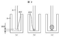
- a method may be considered in which a minute gap 202 is provided at the bottom surface of the reaction vessel 201 and the tip of the sample probe 3 and discharged, and the sample probe 3 is raised before the discharged sample rises to the side surface of the sample probe 3.
- the sample cannot be spotted accurately on the bottom surface 201 of the reaction container, and the sample that should have been discharged may move to the side surface of the sample probe 3 and bring the sample back.
- the discharged sample does not fully adjust to the reaction vessel bottom surface 201, and the sample probe 3 is moved toward the sample probe 3 as shown in FIG. It may be left behind.
- a very small amount of sample is discharged, a larger amount of sample remains on the side surface of the sample probe 3 than the amount of sample discharged to the reaction vessel bottom surface 201, which may cause a decrease in dispensing accuracy. Absent.
- FIG. 4A the first sample discharge is performed with a minute gap 202 opened between the sample probe 3 and the reaction vessel bottom surface 201 (FIG. 4B).
- the sample discharge amount is set to be equal to or less than the dispensing amount determined from the limit liquid ball holding height 203 that can be held by the sample probe 3 shown in FIG.
- the distance of the gap 202 from 201 is controlled to be not more than the limit liquid ball holding height 203 (FIG. 5) that can be held by the sample probe 3 shown in FIG.
- the sample may rise to the side of the sample probe 3 ( (C) on the side of the sample probe 3 in FIG. 2 (c). Dispensing accuracy occurs when the sample is discharged for the second time and thereafter, the sample is not spotted on the bottom surface 201, and when the sample probe 3 is raised, the sample is scattered on the side surface of the reaction container 5. This is because it may cause trouble.
- the actual limit liquid ball holding height 203 formed at the tip of the sample probe 3 is smaller than the limit liquid ball holding height.
- the gap 202 between the tip of the sample probe 3 and the bottom surface 201 of the reaction vessel needs to be set to be small in accordance with the size of the actual limit liquid ball holding height 203 formed at the tip of the sample probe 3.
- the size of the liquid ball 204 that can be held at the tip of the sample probe 3 varies depending on the diameter and sample type of the tip of the sample probe 3.
- the limit liquid ball holding height that can be held at the tip of the sample probe 3 Is 0.3 mm, it can be seen that the gap 202 between the tip of the sample probe 3 and the bottom surface 201 of the reaction vessel must be controlled to 0.3 mm or less.
- a predetermined value can be used as the viscosity of the sample, or a pressure gauge 152 or the like is incorporated in a part of the flow path connected to the sample probe, and information on the viscosity of the sample is obtained from the pressure waveform when the sample is sucked. You can also get It is also possible to classify the aspirated sample into serum, urine, control specimen, etc., and perform the sample probe 3 descending control with the optimum gap 202 according to the sample type, thereby controlling the gap 202.
- the sample probe 3 when the sample probe 3 having an outer diameter of ⁇ 0.4 mm is used and the required discharge amount is set to 1 ⁇ L, the sample probe 3 is controlled so that the gap 202 with the reaction vessel bottom surface 201 is stopped at 0.3 mm or less.
- the length of the tube of the sample probe 3 from the sample pump 107 is 1 meter, and the discharge speed of the sample discharged from the tip of the sample probe 3 of the sample pushed out from the syringe pump 107 is 1 ⁇ L / s to 50 ⁇ L / s.
- the sample should be equivalent to water and serum.
- the sample When a sample of 0.04 ⁇ L is discharged to the reaction container bottom surface 201 by the first discharge, the sample is sufficiently wetted and spread on the reaction container bottom surface 201 as shown in FIG. Wait until the wetting and spreading starts, and then dispense the remaining 0.96 ⁇ L of sample as the second discharge. Since the second discharge is performed after the sample is sufficiently wetted and spread on the reaction vessel bottom surface 201 by the first discharge, the sample does not rise on the side surface of the sample probe 3 as shown in FIG. Under the conditions evaluated here, the waiting time required until the sample fully wets and spreads on the bottom surface 201 of the reaction container after the completion of the first discharge operation at the discharge speed of 5 ⁇ L / s to 25 ⁇ L / s for both sample water and serum. The time needs 10 ms or more.
- the second discharge is performed while maintaining the gap 202, the contact area between the side surface of the sample probe 3 and the discharged sample increases as shown in FIG. 4E, and the sample adheres to the side surface of the sample probe 3. Therefore, it is desirable that the second discharge is performed while raising the sample probe 3 as shown in FIG. 4D, and the discharge is performed without attaching the sample to the side surface of the sample probe 3.
- the waiting time until the first discharge and wetting spread is 10 ms or more.
- the tube length of the sample probe 3 and the suction discharge are performed from the sample pump 107.
- the time from the end of the discharge operation of the syringe pump 107 until the sample in the sample probe 3 completely stops depends on the apparatus configuration.
- the waiting time for the discharged sample to spread on the bottom surface 201 of the reaction vessel varies depending on the apparatus configuration.
- the sample probe 3 when the sample probe 3 is lowered in advance with the liquid ball 204 at the tip of the sample probe 3 in the first discharge, the sample probe 3 is held at the tip of the sample probe 3 as shown in FIG. 6B.
- the liquid ball 204 contacts the reaction vessel bottom surface 201.
- the liquid level detection circuit 151 detects the capacitance that changes when the liquid ball 204 comes into contact with the reaction vessel bottom surface 201 and stops the descent of the sample probe 3, the tip between the sample probe 3 and the reaction vessel bottom surface 201 is stopped. It is possible to optimize the distance.
- the sample held at the tip of the sample probe 3 waits until the sample sufficiently wets and spreads on the reaction vessel bottom surface 201 as shown in FIG.
- the sample is discharged up to the set discharge amount.
- the sample probe 3 can be prevented from adhering to the side surface of the sample probe 3 by raising the sample probe 3 as shown in FIG.
- Measurement is performed by the pressure sensor 152 or the like arranged on the sample probe 3 flow path, and the descent of the sample probe 3 is stopped. A certain period of time is provided until the sample held at the tip of the sample probe 3 by the first discharge sufficiently wets and spreads on the bottom surface 201 of the reaction vessel as shown in FIG. Discharge to the set discharge amount in the second discharge. Also in this case, as shown in FIG. 6D, the second discharge is performed while raising the sample probe 3, thereby enabling discharge without attaching the sample to the side surface of the sample probe 3.
- the pressure sensor 152 is arranged on the sample probe 3 flow path as in the previous embodiment.
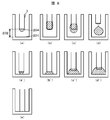
- the liquid ball 204 is first attached to the lower surface of the sample probe 3 as shown in FIG. If the discharge is continued, typically, when the discharge amount exceeds the volume shown in Table 1 or Table 2, it rises to the side surface of the sample probe 3 as shown in FIG. When the discharge is continued and typically exceeds 5 microliters, a droplet shape is formed covering the side surface and the lower surface of the sample probe 3 as shown in FIG. When the discharge is further continued, typically, when it exceeds 15 microliters, the droplet falls as shown in FIG.
- FIGS. 8E When the same amount as the conditions of (a) to (d) is being discharged and the gap 202 is small and the droplet 204 is in contact with the bottom surface 201 of the reaction vessel, FIGS. It becomes a droplet shape like '). Further, when the gap 202 is very small, as shown in FIG. 8E, the clogging occurs and the liquid is not discharged from the sample probe 3.
- a pressure difference called a Laplace pressure is generated between the outside and inside of the droplet due to the surface tension, which is determined by the surface tension of the liquid and the curvature of the surface shape.
- the curvature of the droplet surface is different, so that the state is determined by measuring the pressure with the pressure sensor 152. Can be determined. Further, the state of (e) is high because the liquid is blocked in the sample probe 3, and can be easily discriminated by measuring the pressure with the pressure sensor 152.
- Some methods can be considered depending on how much amount is discharged and pressure is measured, and what kind of operation is selected after pressure measurement.
- the first method is to stop the discharge at the discharge amount shown in FIG. 8A or 8A and measure the pressure. If the pressure measurement result shows that the pressure can be determined to be in the state (a), the sample probe 3 is lowered to the state (a ′). If the pressure can be determined to be the state (e), the sample probe 3 is raised to the state (a ′). After the state (a ′) is reached, the second and subsequent discharges are started, and sample discharge is performed up to the set discharge amount.
- the pressure since the pressure is detected by temporarily stopping the discharge before the droplet rises on the side surface of the probe, the pressure can be detected in a stationary state, and the state can be accurately determined.
- the pressures in the state (a) and the state (a ′) are compared, the difference in the curvature of the droplet shape is large and the difference in the Laplace pressure is large.
- the state can be determined with reliability.
- the liquid stops before the liquid rises on the side surface of the probe and drops are brought into contact with the bottom surface of the reaction container. It is possible to provide an automatic analyzer capable of high-precision analysis.
- the probe is lowered or raised according to the determined result, so even if the gap between the probe and the reaction container fluctuates, the discharge result is not affected and high reliability is achieved.
- An automatic analyzer capable of high-precision analysis by dispensing can be provided.
- the discharge is stopped at the discharge amount shown in FIG. 8B or 8B ', and the pressure is measured.
- the pressure is measured.
- the sample probe 3 is lowered to the state (b ′).
- the pressure can be determined to be the state (e)
- the sample probe 3 is raised to the state (b ′).
- the predetermined discharge amount is larger than the first discharge amount, the second and subsequent discharges are performed thereafter.
- FIG. 9 shows an example of the measurement result of pressure when operating under these conditions. There is a clear difference in pressure between the state (b ′) in which the liquid droplet is in contact and the state in (b) where the liquid droplet is not in contact, and discrimination is possible.
- FIG. 10 shows an example of the pressure measurement result when the discharge amount exceeds (b) or (b ′) and reaches the discharge amount (c) or (c ′). In this case, since the pressure difference between the contact state and the non-contact state is small, the determination becomes difficult.
- the pressure in the state of (b) and the state of (b ′) is compared, the difference in curvature of the droplet shape is large, and the difference in Laplace pressure is large.
- the state can be determined with high reliability.
- an automatic analyzer that can perform analysis at a high speed because the time required for dispensing is short. Can be provided.
- the pressure is detected by temporarily stopping, so that the Laplace pressure difference is small as shown in FIG.
- an automatic analyzer that can perform highly accurate analysis by dispensing with high reliability Can provide.
- the discharge is temporarily stopped and the pressure is measured. Therefore, it is added after confirming that the droplet is in contact with the bottom surface of the reaction vessel.
- the probe can be raised while discharging, and the amount of liquid adhering to the side surface of the probe can be reduced, so that highly accurate dispensing can be realized.
- a predetermined discharge amount is discharged without being divided, the pressure is measured after discharge, the state of the droplet is determined, and a corresponding operation based on the result is performed. is there.
- the gap 202 is appropriate, the state after the end of discharge becomes one of FIGS. 8A 'to 8D' depending on the predetermined discharge amount. If the gap 202 is larger than appropriate, one of FIGS. 8A to 8D is obtained. If the gap 202 is too small, the state shown in FIG. The state is determined from the pressure and the corresponding action is performed.
- Specific countermeasure operations include controlling the height of the probe to move to an appropriate position, or warning the abnormality and canceling the subsequent operation.
- the state of the droplet can be determined by pressure detection, it can be dealt with, so that even if the height of the probe fluctuates, it can be dispensed correctly and a highly accurate analyzer can be provided. There is.
- the discharge is performed by one discharge without dividing, the time required for dispensing can be shortened, and an automatic analyzer with high throughput can be provided.
- the sample probe 3 When the first discharge is performed by the above method, the sample is wetted and spread on the bottom surface 201 of the reaction vessel, and the sample probe 3 is discharged without being raised by the second discharge, the sample probe is as shown in FIG. It is conceivable that the contact area between the three side surfaces and the discharged sample increases, and the sample adhesion to the side surfaces of the sample probe 3 increases when the sample probe 3 is pulled up. As described above, it is effective to discharge while raising the sample probe 3 in order to reduce the sample adhesion to the side surface of the sample probe 3. However, when the sample discharge amount is large, the sample viscosity may be reduced due to the viscosity of the sample.
- the third discharge operation is performed while the sample probe 3 is further raised by the third discharge as shown in FIG.
- the viscosity of the sample is measured by the pressure sensor 152 or the like installed on the pipe of the sample probe 3, and the sample is wetted on the reaction vessel bottom surface 201 by the first discharge.
- the discharge operation is divided into three discharges.
- the present invention does not strictly define the number of discharges according to the discharge amount.
- the set discharge amount may be divided into several times. In a field where a sample is dispensed in a minute amount using a probe or a tip and dispensing accuracy is required, the range of use is not limited to an automatic analyzer.
Landscapes
- Chemical & Material Sciences (AREA)
- Health & Medical Sciences (AREA)
- Analytical Chemistry (AREA)
- Chemical Kinetics & Catalysis (AREA)
- Physics & Mathematics (AREA)
- Life Sciences & Earth Sciences (AREA)
- Clinical Laboratory Science (AREA)
- Biochemistry (AREA)
- General Health & Medical Sciences (AREA)
- General Physics & Mathematics (AREA)
- Immunology (AREA)
- Pathology (AREA)
- Automatic Analysis And Handling Materials Therefor (AREA)
Abstract
空の反応容器にサンプルを吐出する際にサンプルプローブ先端を反応容器の底に接触させないで分注動作を行い、サンプルプローブと反応容器の長寿命化を図ると共に、安定した分注精度でサンプルの分注ができる自動分析装置を提供する。 反応容器に分注時、サンプルプローブと反応容器底面に一定の隙間を設け、設定吐出量を一度に吐出するのではなく、設定吐出量を分割して吐出を行い、1回目の吐出で反応容器底面に吐出したサンプルが濡れ広がる時間を設け、サンプルが反応容器底面に濡れ広がった後に、2回目以降の吐出を行うことで、サンプルプローブへの持ち帰りのない、安定した分注精度でサンプルの分注ができることを可能とした。
Description
本発明は、血液,尿等の生体試料の成分の分析を自動的に実行する自動分析装置に係り、特に、試料容器や試薬容器から液体を採取して反応容器に分注する自動分析装置に関する。
自動分析装置において、正確な測定を行うためにサンプルや試薬(以下、簡略のために単にサンプルとのみ称す)は確実に反応容器底面に分注することが必須であり、サンプルの空分注、持ち帰りがあってはならない。従来のサンプルを反応容器に分注する分注機構では、サンプルプローブ先端を斜めにカットし、サンプルプローブを反応容器底面に押し付けた状態でサンプル用ポンプを介して分注することにより、確実に反応容器底面に分注を行っている。
また、特許文献1には、10μL程度の微量分注を目的として、プローブ先端と容器底面との距離を最適に制御することで精度良い微量分注を達成する方法が開示されている。
上記従来技術には、以下の欠点がある。
まず、反応容器の底に斜めにカットされたサンプルプローブ先端を毎回接触させて試料を分注するため、サンプルプローブの先端や反応容器の底面がダメージを受け、分注精度低下につながることがある。特に最近はサンプル分注量が1μL以下と少ない量で分注精度を維持するためにサンプルプローブ先端径が細く尖がっており、反応容器の底やサンプルプローブ先端がダメージを受けやすい。安定した正確な分注を行うためには、反応容器の底やサンプルプローブ先端にダメージを与えずに、微量分注を実現することが必要である。
また、反応容器底面にサンプルプローブを押し付けた状態(しなっている状態)でサンプル分注動作を行うため、サンプル分注後にサンプルプローブが上昇すると、サンプルプローブ側面にサンプルが付着し、サンプルの持ち帰りにつながることがある。また、サンプルプローブが押し付けられた状態から上昇時に元の状態(しなりの無い状態)に戻ることによりサンプルプローブの振動がサンプルプローブ側面、カット先端部についたサンプルを反応容器側面へ飛散らせることがある。結果として設定分注量を分注していないことになる。
更に、特許文献1に開示された方法により、サンプルプローブ先端と反応容器底面との間に微小な隙間を設けて微量分注を行った場合であっても、サンプルの微量ゆえに反応容器底面に接触しても反応容器底面に確実に点着とまではいかず、結果としてサンプルプローブ先端に付着したまま持ち帰られることもあった。
上記問題は、微量分注になるほど影響が大きくなり、測定結果の信頼性に影響を及ぼすことが多い。本発明の目的は、サンプルプローブの先端や反応容器の底のダメージを与えず、且つ、サンプルプローブ側面へのサンプル付着をさせずに微量分注精度が維持できる自動分析装置を提供することにある。
上記目的を達成するための本発明の構成は以下の通りである。
液体を吸引・吐出するプローブと、前記プローブから吐出される液体を収容する容器と、前記プローブが吸引した液体を前記容器に吐出する際に、前記液体を複数回に分割して吐出をさせるシリンジ機構と、を備えた自動分析装置。
ここで、液体とはサンプルや試薬などを、容器とは反応分析部上の反応容器を意味する。
本発明によれば、サンプルプローブ先端を反応容器底面に接触させることなく、サンプル吐出動作が可能となる。サンプルプローブ先端と反応容器の底を接触させないので、プローブや反応容器にダメージを与えないので長寿命化が図ることができる。
また、隙間を設けて吐出する時に起こる、サンプルを反応容器底面に吐出したときに、設定吐出量を反応容器底面に吐出できずにサンプルプローブ側面に付着させて持ち帰ってしまうことによる分注精度の低下を、1回目の吐出で反応容器側面にサンプルを濡れ広がらせることで、防止することが可能となり信頼性の向上を図ることができる。
以下、図面を用いて本発明の実施例を説明する。
図1に本発明が実施される一般的な自動分析装置の概略を示す。各部の機能は公知のものであるため、詳細についての記述は省略する。サンプリング機構1のサンプリングアーム2は上下すると共に回転し、サンプリングアーム2に取り付けられたサンプルプローブ3を用いて、左右に回転するサンプルディスク102に配置された試料容器101内の試料を吸引し、反応容器5へ分注するように構成されている。本図からもわかるように試料容器101のサンプルディスク102上への配置はサンプルディスク102上へ直接配置する場合や試験管(図示は無い)上に試料容器101を載せることも可能なユニバーサルな配置に対応可能な構造のものが一般的である。
回転自在な試薬ディスク125上には分析対象となる複数の分析項目に対応する試薬ボトル112が配置されている。可動アームに取り付けられた試薬分注プローブ110は、試薬ボトル112から反応容器5へ所定量の試薬を分注する。
サンプルプローブ3は、サンプル用シリンジポンプ107の動作に伴ってサンプルの吸引動作、及び分注動作を実行する。試薬分注プローブ110は、試薬用ポンプ111の動作に伴って試薬の吸引動作、及び分注動作を実行する。各試料のために分析すべき分析項目は、キーボード121、又はCRT118の画面のような入力装置から入力される。この自動分析装置における各ユニットの動作はコンピュータ103により制御される。
サンプルディスク102の間欠回転に伴って試料容器101はサンプル吸引位置へ移送され、停止中の試料容器内にサンプルプローブ3が降下される。その下降動作に伴ってサンプルプローブ3の先端が試料の液面に接触すると液面検出回路151から検出信号が出力され、それに基づいてコンピュータ103がサンプリングアーム2の駆動部の下降動作を停止するよう制御する。次にサンプルプローブ3内に所定量の試料を吸引した後、サンプルプローブ3は上死点まで上昇する。サンプルプローブ3が試料を所定量吸引している間は、サンプルプローブ3とサンプル用ポンプ107流路間の吸引動作中の流路内圧力変動を圧力センサ152からの信号を用い圧力検出回路153で監視し、吸引中の圧力変動に異常を発見した場合は所定量吸引されていない可能性が高いため、当該分析データに対しアラームを付加する。
次にサンプリングアーム2が水平方向に旋回し反応ディスク4上の反応容器5の位置でサンプルプローブ3を下降し反応容器5内へ保持していた試料を分注する。試料が入った反応容器5が試薬添加位置まで移動された時に、該当する分析項目に対応した試薬が試薬分注プローブ110から添加される。サンプル、及び試薬の分注に伴って試料容器101内の試料、及び試薬ボトル112内の試薬の液面が検出される。試料、及び試薬が加えられた反応容器内の混合物は、攪拌機構113により攪拌される。混合物が収納された反応容器が光度計115に移送され、各混合物の発光値、或いは吸光度が測定手段としての光電子増倍管、或いは光度計により測定される。発光信号或いは受光信号は、A/D変換器116を経由しインターフェース104を介してコンピュータ103に入り、分析項目の濃度が計算される。分析結果は、インターフェース104を介してプリンタ117に印字出力するか、又はCRT118に画面出力すると共に、メモリ122に格納される。測光が終了した反応容器5は、反応容器洗浄機構119の位置にて洗浄される。洗浄用ポンプ120は、反応容器へ洗浄水を供給すると共に、反応容器から廃液を排出する。図1の例では、サンプルディスク102に同心円状に3列の試料容器101がセットできるように3列の容器保持部が形成されており、サンプルプローブ3による試料吸引位置が各々の列に1個ずつ設定されている。
以上が自動分析装置の一般的な動作である。
サンプルの分注精度向上を図るためには、サンプルプローブ3側面にサンプルを付着させずに吐出する必要がある。そのためには、反応容器底面201とサンプルプローブ3先端に微小な隙間202を設けて吐出し、吐出したサンプルがサンプルプローブ3側面にせり上がる前にサンプルプローブ3を上昇させる方法が考えられる。しかし、前記吐出方法にはサンプルを反応容器底面201に正確に点着できずに、吐出したはずのサンプルがサンプルプローブ3側面に移動してしまいサンプルを持ち帰ってしまうことがあった。
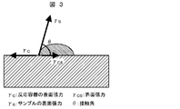
図2を用いて、サンプルプローブ3先端と反応容器底面201との間に微小な隙間202を設けて(図2(a))吐出する際に起こるサンプル持ち帰りについて説明する。平面上に存在している液滴(図3の状態)における界面張力のつりあいは、以下の数式が成り立つ。
(数式1)
γC=γCS+γScosθ
図2(a)のように隙間202を設けた状態でサンプルを吐出した際(図2(b))、反応容器底面201にサンプルが接触すると、反応容器底面201とサンプル間の界面構造が変化し、界面張力γCSが小さくなる。
(数式2)
cosθ=(γC-γCS)/γS
数式1の変形により数式2が成り立ち、γCおよびγSが一定であればγCSが小さくなるにつれてcosθは大きくなる。0°≦θ≦180°のため、cosθが大きくなると接触角θが小さくなりサンプルが反応容器底面201に濡れ広がることが分かる。このサンプルの濡れ広がりには、反応容器底面201とサンプル間の界面構造の変化による、界面エネルギーが低下する待ち時間を要する。この待ち時間は液体と反応容器底面201の表面の化学組成に依存するため、分注する液体の種類や、反応容器の材質,形状等によって最適な待ち時間は異なると考えられる。
仮に吐出したサンプルが反応容器底面201に濡れ広がる前にサンプルプローブ3を上昇させると、吐出されたサンプルが反応容器底面201に十分に馴染まず、図2(c)のようにサンプルプローブ3側に残ってしまうことが考えられる。特に微量のサンプルを吐出する場合は、反応容器底面201に吐出されるサンプルの量よりも、サンプルプローブ3側面に残るサンプルの量が多く残ってしまうために、分注精度低下の原因につながりかねない。
上記問題に鑑み、本発明の実施形態の一つを図4に示す。図4(a)のようにサンプルプローブ3と反応容器底面201との間に微小な隙間202を開けた状態で1回目のサンプル吐出を行う(図4(b))。このときの(1回目のサンプル吐出時)におけるサンプル吐出量は図5に示すサンプルプローブ3で保持可能な限界液玉保持高さ203から定まる分注量以下とし、サンプルプローブ3先端と反応容器底面201との隙間202の距離は、図5に示すサンプルプローブ3で保持可能な限界液玉保持高さ203(図5)以下となるよう制御する。仮に、1回目のサンプル吐出時にサンプルプローブ3先端で保持可能な限界液玉保持高さ203以上の大きさに相当する液体を吐出すると、サンプルプローブ3側面にサンプルがせり上がってしまうことがあり(図2(c)のサンプルプローブ3側)、2回目以降のサンプル吐出時に反応容器底面201に対するサンプルの点着不良、サンプルプローブ3上昇時に反応容器5側面へのサンプル飛散などを生じ、分注精度に支障をきたすことがあるためである。
1回目の吐出量を前記限界液玉保持高さよりも少ない吐出量に設定した場合は、サンプルプローブ3先端に作られる実際の限界液玉保持高さ203は限界液球保持高さよりも小さくなるので、サンプルプローブ3先端と反応容器底面201の隙間202は、サンプルプローブ3先端に作られる実際の限界液玉保持高さ203の大きさに合わせて小さくなるように設定する必要がある。
図5や表1,表2に示すようにサンプルプローブ3先端の直径及びサンプル種類によってサンプルプローブ3先端で保持できる液玉204の大きさは異なってくる。例えば、表1の外径φ0.4mmのサンプルプローブ3を用いると、粘性等の性状が水相当のサンプルを吸引,吐出する場合には、サンプルプローブ3先端で保持可能な限界液玉保持高さが0.3mmなので、サンプルプローブ3先端と反応容器底面201の隙間202は0.3mm以下に制御しなければならないことがわかる。


サンプルの粘性は、予め定められた値を用いることもできるし、サンプルプローブにつながる流路の一部に圧力計152等を組込み、サンプルを吸引するときの圧力波形等からサンプルの粘性等に関する情報を得ることもできる。吸引したサンプルを、血清,尿,コントロール検体等に種類分けを行い、サンプル種別に合わせて最適な隙間202でサンプルプローブ3下降制御を行い、隙間202を制御させることも可能である。
ここで、外径φ0.4mmのサンプルプローブ3を使用し、必要吐出量を1μLとした場合、サンプルプローブ3を反応容器底面201との隙間202を0.3mm以下で止めるように制御し、サンプル吐出を2回に分割して行う場合を考える。サンプル用ポンプ107からサンプルプローブ3のチューブ長の長さを1メートル、シリンジ用ポンプ107から押し出されるサンプルのサンプルプローブ3先端から吐出されるサンプルの吐出速度は1μL/s~50μL/sとし、評価サンプルを水相当,血清相当とする。
1回目の吐出で0.04μLのサンプルを反応容器底面201に吐出をした場合、1回目の吐出後、図4(c)のようにサンプルが反応容器底面201に十分に濡れ広がるまで、もしくはサンプルの濡れ広がりが始まるまで待ってから、残りのサンプル0.96μLを2回目の吐出として分注する。1回目の吐出で反応容器底面201にサンプルを十分に濡れ広がらせてから2回目の吐出を行っているので、図2(c)のようにサンプルプローブ3側面にサンプルがせり上がることはない。ここで評価した条件下においてはサンプル水相当,血清相当共に、吐出速度5μL/s~25μL/sにおいて、1回目の吐出動作終了後にサンプルが反応容器底面201に十分に濡れ広がるまでに必要な待ち時間は10ms以上必要である。
2回目の吐出で隙間202を維持したまま吐出すると、図4(e)のようにサンプルプローブ3側面と吐出したサンプルの接触面積が増加し、サンプルプローブ3側面へサンプルが付着してしまう。そのため、2回目の吐出では、図4(d)のようにサンプルプローブ3を上昇させながら行い、サンプルプローブ3の側面にサンプルを付着させない吐出を行うことが望ましい。上記記載した吐出条件において、1回目に吐出し、濡れ広がるまでの待ち時間は10ms以上必要としたが、実際の装置構成においては、サンプル用ポンプ107からサンプルプローブ3のチューブ長さ,吸引吐出するサンプルの種別,サンプルプローブ3先端からの吐出速度、等により、シリンジ用ポンプ107の吐出動作終了後からサンプルプローブ3内のサンプルが完全に停止するまでの時間等は装置構成により異なる。
従って、吐出したサンプルが反応容器底面201に濡れ広がる待ち時間は装置構成により異なる。
図6を用いて本発明の他の実施例を説明する。
図6(a)のように、1回目の吐出で予めサンプルプローブ3先端に液玉204がある状態でサンプルプローブ3を下降させると図6(b)のように、サンプルプローブ3先端に保持した液玉204が反応容器底面201に接触する。液玉204が反応容器底面201に接触したときに変化する静電容量を液面検出回路151で検知してサンプルプローブ3の下降を停止させれば、サンプルプローブ3先端と反応容器底面201との距離を最適にすることが可能となる。その後、サンプルプローブ3先端に保持していたサンプルが図6(c)のように反応容器底面201に十分に濡れ広がるまで、もしくはサンプルの濡れ広がりが始まるまで待ってから、2回目の吐出を行い、設定した吐出量までサンプル吐出を行う。2回目の吐出においては、図6(d)のようにサンプルプローブ3を上昇させながら行うことによって、サンプルプローブ3側面へのサンプル付着を防ぐことができる。
液玉204と反応容器底面201との接触を検出する他の方法としては、反応容器底面201へのサンプルの広がりを圧力値変化から検知する方法がある。図6(a)のように、1回目の吐出で予めサンプルプローブ3先端に液玉204がある状態でサンプルプローブ3を下降させると図6(b)のように予め作った液玉204が反応容器底面201に接触する。図6(b)から図6(c)の状態に変化する(液玉204が反応容器の底面201に濡れ広がる)とき、サンプルプローブ3流路内の圧力が変化するので、そのとき圧力変化をサンプルプローブ3流路上に配置してある圧力センサ152等で測定し、サンプルプローブ3の下降を停止させる。1回目の吐出でサンプルプローブ3先端に保持していたサンプルが図6(c)のように反応容器底面201に十分に濡れ広がるまで、もしくはサンプルの濡れ広がりが始まるまで、ある一定の時間を設け2回目の吐出で設定吐出量まで吐出を行う。この場合も、図6(d)のように2回目の吐出はサンプルプローブ3を上昇させながら行うことで、サンプルプローブ3の側面にサンプルを付着させない吐出が可能となる。
図8を用いて本発明の他の実施例を説明する。
本実施例の構成は、前実施例と同じく、サンプルプローブ3流路上に圧力センサ152を配置している。
サンプルプローブ3先端と、反応容器底面201との間の隙間202が小さくない場合に吐出を開始すると、液球204はまず図8(a)のようにサンプルプローブ3の下面に付着している。吐出を続けると、典型的には吐出量が表1または表2に示した体積を越えると図8(b)のようにサンプルプローブ3の側面にせり上がる。更に吐出を続け、典型的には5マイクロリットルを越えると、図8(c)に示したようにサンプルプローブ3の側面と下面を包んだ液滴形状となる。更に吐出を続けると、典型的には15マイクロリットルを越えると、図8(d)のように液滴は落下する。(a)から(d)の条件と同じ量を吐出している状態で、隙間202が小さく液滴204が反応容器底面201に接触している場合は、それぞれ図8(a′)~(d′)のような液滴形状となる。また、隙間202がごく小さい場合は、図8(e)のように閉塞が生じて液がサンプルプローブ3から吐出されない状態になる。
液滴の外部と内部の間には表面張力のためラプラス圧と呼ばれる圧力差が生じており、それは液体の表面張力の大きさと、表面形状の曲率で決定される。図8の(a)~(d),(a′)~(d′)のそれぞれの状態で、液滴表面の曲率が異なるので、圧力センサ152で圧力を測定することにより、どの状態であるかが判別可能である。また(e)の状態は、液がサンプルプローブ3内で閉塞されているので圧力が高くなり、圧力センサ152での圧力測定により容易に判別ができる。
本実施例の動作は、サンプルプローブ3から一定量の液を吐出後、圧力センサ152で圧力を測定し、その結果に応じてその後の動作を変えるようにする。
どれだけの量を吐出してから圧力測定するか、および圧力測定してからどういう動作を選択するかでいくつかの方式が考えられる。
第1方式としては、図8(a)または(a′)となる吐出量で吐出を止めて、圧力を測定することである。圧力測定結果、(a)の状態と判断できる圧力であった場合は、サンプルプローブ3を下降して(a′)の状態にする。(e)の状態と判断できる圧力であった場合は、サンプルプローブ3を上昇させて、(a′)の状態にする。(a′)の状態になってから2回目以降の吐出を開始し、設定した吐出量までサンプル吐出を行う。
本実施例の第1方式の場合、液滴がプローブ側面にせり上がる前に吐出を一旦止めて圧力を検出するので、静止した状態で圧力検知ができ、状態の判別が正確に行える。
また本実施例の第1方式の場合、(a)の状態と(a′)の状態の圧力の比較を行うので、液滴形状の曲率の違いが大きく、ラプラス圧の差が大きいので、高い信頼性で状態の判別ができる。
また本実施例の第1方式の場合、プローブ側面に液がせり上がる前に停止して液滴を反応容器底面に接触させるので、プローブ側面が濡れてしまうことによる分注量の変動を避けることが可能であり、高精度の分析が可能な自動分析装置を提供できる。
また本実施例の第1方式の場合、判別した結果に応じてプローブを下降または上昇するので、プローブと反応容器の隙間の大きさが変動しても吐出結果に影響せず、高い信頼性の分注により高精度の分析が可能な自動分析装置を提供できる。
また本実施例の第1方式の場合、プローブの高さの制御精度が低くても調整されるので、プローブの高さ制御の機構を簡略化でき、低コストの自動分析装置を提供できる。
本実施例の第2方式は、図8(b)または(b′)となる吐出量で吐出を止めて、圧力を測定する。圧力測定結果、(b)の状態と判断できる圧力であった場合は、サンプルプローブ3を下降して(b′)の状態にする。(e)の状態と判断できる圧力であった場合は、サンプルプローブ3を上昇させて、(b′)の状態にする。所定の吐出量が1回目の吐出量より多い場合は、その後2回目以降の吐出を行う。
図9は本条件で動作させた場合の圧力の測定結果の例である。液滴が接触している(b′)の状態と、非接触の(b)の状態では圧力に明確な差があり、判別が可能である。なお、(b)または(b′)となる吐出量を超えて、(c)または(c′)となる吐出量まで吐出した場合の圧力測定結果の例が図10である。この場合、接触状態と非接触状態との圧力差は小さいので、判別は難しくなる。
本実施例の第2方式の場合も、吐出を一旦止めて圧力を検知するので、第1方式とほぼ同じ効果が得られる。
また、本実施例の第2方式の場合、(b)の状態と(b′)の状態の圧力の比較を行うので、液滴形状の曲率の違いが大きく、ラプラス圧の差が大きいので、高い信頼性で状態の判別ができる。
また、本方式の第2方式の場合は、第1方式と違い(a)の状態で一旦停止することはないので、分注に要する時間が短くて済み、高速で分析ができる自動分析装置が提供できる。
また、本実施例の第2方式の場合は、所定の吐出量が5マイクロリットル以上のように大きい場合に、一旦止めて圧力を検出するため、図10のようにラプラス圧の差が小さい条件でなく、図9のようにラプラス圧の差が大きい条件で液滴が反応容器の底面に接触しているかどうかを判定できるので、信頼性の高い分注により高精度の分析ができる自動分析装置を提供できる。
さらに本実施例の第2方式では、所定の吐出量が多い場合に、一旦吐出を停止して圧力を測定するので、液滴が反応容器の底面に接触している状態を確認してから追加吐出をさせながらプローブを上昇させることができ、プローブ側面に液が付着する量を少なくし、高精度な分注が実現可能である。
また、本実施例の第2方式の場合、圧力測定により液滴が反応容器の底部に接触していないと判断した場合には、何らかの異常があると見なし、続く動作を停止させて警告を発するように制御することも可能である。
本実施例の第3方式としては、所定の吐出量を分割せずに吐出し、吐出後に圧力を測定して、液滴の状態を判別して、その結果に基づいた対応動作をさせることである。隙間202が適正であった場合は、吐出終了後の状態は所定の吐出量の大小により図8(a′)~(d′)のいずれかになる。隙間202が適正より大きかった場合は、図8(a)~(d)のいずれかになる。隙間202が小さ過ぎた場合は図8(e)の状態になる。どの状態になっているかを圧力から判別し、対応動作をする。具体的な対応動作は、プローブの高さを制御して適性位置に移動することや、異常を警告して引き続く動作を取りやめることなどである。
本実施例の第3方式においても、圧力検知により液滴の状態を判別して対応できるので、プローブの高さに変動が生じても正しく分注ができ、高精度の分析装置が提供できる効果がある。
また本実施例の第3方式においては、吐出を分割せずに1回の吐出で行うので、分注に要する時間が短くて済み、高い処理能力の自動分析装置が提供可能である。
次に吐出設定量が多い場合における本発明の実施例を説明する。
上記方法で1回目の吐出を行い、反応容器底面201にサンプルを濡れ広がらせたあと、2回目の吐出でサンプルプローブ3を上昇させないで吐出を行うと、図7(a)のようにサンプルプローブ3側面と吐出したサンプルの接触面積が増加し、サンプルプローブ3を引き上げたときにサンプルプローブ3側面へのサンプル付着が増えてしまうことが考えられる。サンプルプローブ3側面へのサンプル付着を低減させるために、サンプルプローブ3を上昇させながら吐出することが有効であると上記で説明したが、サンプル吐出量が多い場合は、サンプルの粘性等によりサンプルの吐出速度が変化し、吐出設定量の全てを吐出するのに必要な時間とサンプルプローブ上昇時間の関係が不安定となる可能性があるためである。つまり、サンプルプローブ3を上昇させながら吐出をしても、吐出したサンプルの液面高さの上昇速度がサンプルプローブ上昇速度よりも遅いためにサンプルプローブ3先端からサンプルが飛散することや、サンプルプローブ上昇速度よりもサンプル液高さの上昇速度が早いためにサンプルプローブ3側面にサンプル付着してしまうことが考えられる。
この問題を解決する手段を、図7(b)~(d)を用いて説明する。図7(b)のように1回目の吐出で反応容器底面201にサンプルを濡れ広がらせるまで待った後、図7(c)のように2回目の吐出で、サンプルプローブ3を吐出させながら上昇させることでサンプルプローブ側面への付着は低減できる。反応容器の断面積が大きい場合などは、1回目の高さと同じ位置で2回目の吐出を行い、吐出終了後にサンプルプローブ3を上昇させても、2回目に吐出する設定量をサンプルプローブ側面にせり上がらない設定量にすることでサンプルプローブ側面への付着は低減できる。
2回目の吐出が終了してから、図7(d)のように3回目の吐出で、さらにサンプルプローブ3を上昇させながら3回目の吐出動作を行う。
このように段階的にサンプルプローブを上昇させながら吐出を行うことで、吐出設定量が多い場合であってもサンプルプローブ3側面へのサンプル付着を低減でき、分注精度を向上させることができる。
本実施形態においても、サンプルを吸引するときにサンプルプローブ3の配管上に設置された圧力センサ152等でサンプルの粘性等を測定しておき、1回目の吐出で反応容器底面201にサンプルを濡れ広がらせた後、2回目の吐出でサンプルプローブ3を上昇させながら動作させるときに、サンプルプローブ3の上昇速度をサンプル種別によって変え、サンプルプローブ3側面にサンプルを付着させない方法も考えられる。
本実施例では、自動分析装置の一例として吐出動作を3回に分けて吐出する例としたが、本発明は吐出量に応じて吐出する回数を厳密に規定するものではなく、吐出量やサンプル種類によっては設定吐出量を何回かに分けて行っても良い。プローブやチップを使用してサンプルの微量分注を行い、分注精度を必要とする分野においては使用範囲が自動分析装置に制限されるものではない。
1 サンプリング機構
2 サンプリングアーム
3 サンプルプローブ
4 反応ディスク
5 反応容器
101 試料容器
102 サンプルディスク
103 コンピュータ
104 インターフェース
107 サンプル用ポンプ
110 試薬分注プローブ
111 試薬用ポンプ
112 試薬ボトル
113 攪拌機構
115 光度計
116 A/D変換器
117 プリンタ
118 CRT
119 反応容器洗浄機構
120 洗浄用ポンプ
121 キーボード
122 メモリ
125 試薬ディスク
151 液面検出回路
152 圧力センサ
153 圧力検出回路
201 反応容器底面
202 隙間
203 限界液玉保持高さ
204 液玉
2 サンプリングアーム
3 サンプルプローブ
4 反応ディスク
5 反応容器
101 試料容器
102 サンプルディスク
103 コンピュータ
104 インターフェース
107 サンプル用ポンプ
110 試薬分注プローブ
111 試薬用ポンプ
112 試薬ボトル
113 攪拌機構
115 光度計
116 A/D変換器
117 プリンタ
118 CRT
119 反応容器洗浄機構
120 洗浄用ポンプ
121 キーボード
122 メモリ
125 試薬ディスク
151 液面検出回路
152 圧力センサ
153 圧力検出回路
201 反応容器底面
202 隙間
203 限界液玉保持高さ
204 液玉
Claims (11)
- 液体を吐出するプローブと、
前記プローブから吐出される液体を収容する容器と、
前記液体を複数回に分割して前記プローブが吐出するよう制御するシリンジ機構と、
複数回に分割した吐出のうち、最初の吐出時に前記プローブから吐出された試料が前記容器の底面と接触するよう、前記プローブ先端と前記容器の底面との距離を制御するプローブ駆動機構と、
を備えたことを特徴とする自動分析装置。 - 請求項1記載の自動分析装置において、
前記プローブ駆動機構は、前記最初の吐出後、次の吐出を開始するまでの間には前記プローブ先端と前記容器の底面との間の距離を一定に保つよう制御することを特徴とする自動分析装置。 - 請求項1記載の自動分析装置において、
前記プローブ駆動機構は、少なくとも前記シリンジ機構が最後の吐出を行っている最中に、前記プローブを上昇させるよう制御することを特徴とする自動分析装置。 - 請求項1記載の自動分析装置において、
前記シリンジ機構は、
前記プローブ駆動機構が前記プローブの先端と前記容器の底面とが一定の距離を保った状態で液体を前記容器へ分注する第一の分注制御方法と、
前記プローブ駆動機構が前記プローブを駆動させている状態で液体を前記容器へ分注する第二の分注制御方法と、
を含む複数の制御方法を有することを特徴とする自動分析装置。 - 請求項4記載の自動分析装置において、
前記第一の分注制御方法による分注の後に前記第二の分注制御方法による分注を行う場合には、前記プローブ駆動機構は、前記第一の分注制御方法による分注と、前記第二の分注制御方法による分注との間に待ち時間を設けることを特徴とする自動分析装置。 - 請求項4記載の自動分析装置において、
前記シリンジ機構は、前記プローブ駆動機構が前記プローブ先端と前記容器の底面との間に一定の距離を設けて静止する前に所定量の液体を吐出して前記プローブ先端に液玉を作成する第三の分注制御方法を有し、
前記プローブ先端の液玉が前記容器の底面に接触することによる前記プローブ先端と前記容器の底面との間の静電容量変化を検出する検出回路を備えたことを特徴とする自動分析装置。 - 液体を吐出するプローブと、
前記プローブから吐出される液体を収容する容器と、
前記液体を1以上の複数回に分割して前記プローブが吐出するよう制御するシリンジ機構と、
前記プローブと前記シリンジ機構とを連通する配管内の圧力を検知する圧力センサとを備え,
複数回に分割した吐出のうち、最初の吐出後に前記圧力センサの検出値に基づいて,前記プローブの動作を制御することを特徴とする自動分析装置。 - 請求項4記載の自動分析装置において、
前記プローブと前記シリンジ機構とを連通する配管内の圧力を検知する圧力センサとを備え,
前記プローブ駆動機構は、前記プローブが液体を吸引した際の前記圧力センサの検出値に基づいて、前記プローブの動作を制御することを特徴とする自動分析装置。 - 請求項8記載の自動分析装置において、
前記プローブ駆動機構は、前記圧力センサの検出値に基づいて、前記第一の分注制御方法における前記一定の距離もしくは分注する前記液体の量、前記第二の分注制御方法における前記プローブの上昇速度もしくは分注する前記液体の量、前記第三の分注制御方法における前記プローブ先端に生成する液玉の大きさ、の少なくともいずれかを制御することを特徴とする自動分析装置。 - 液体を吐出するプローブと、
前記プローブから吐出される液体を収容する容器と、を備えた自動分析装置の制御方法であって、
前記プローブの先端と前記容器の底面とが一定の距離を保った状態で前記液体を分注する第一の分注制御方法と、
前記プローブを駆動させている状態で前記液体を分注する第二の分注制御方法と、を有し、
前記プローブから前記容器へ液体を分注する際には前記第一及び第二の分注制御方法を用いて複数回に分割した液体を段階的に分注することを特徴とする自動分析装置の制御方法。 - 請求項10記載の自動分析装置の制御方法において、
前記第一の分注制御方法による分注の後に前記第二の分注制御方法による分注を行う場合には、前記第一の分注制御方法による分注と、前記第二の分注制御方法による分注との間に待ち時間を設けることを特徴とする自動分析装置の制御方法。
Priority Applications (4)
| Application Number | Priority Date | Filing Date | Title |
|---|---|---|---|
| EP10842995.2A EP2525230A4 (en) | 2010-01-13 | 2010-12-10 | AUTOMATIC ANALYZER |
| JP2011549765A JP5686744B2 (ja) | 2010-01-13 | 2010-12-10 | 自動分析装置 |
| CN201080061011.0A CN102695957B (zh) | 2010-01-13 | 2010-12-10 | 自动分析装置 |
| US13/521,094 US20130064737A1 (en) | 2010-01-13 | 2010-12-10 | Automatic analyzer |
Applications Claiming Priority (2)
| Application Number | Priority Date | Filing Date | Title |
|---|---|---|---|
| JP2010004509 | 2010-01-13 | ||
| JP2010-004509 | 2010-01-13 |
Publications (1)
| Publication Number | Publication Date |
|---|---|
| WO2011086635A1 true WO2011086635A1 (ja) | 2011-07-21 |
Family
ID=44303942
Family Applications (1)
| Application Number | Title | Priority Date | Filing Date |
|---|---|---|---|
| PCT/JP2010/007179 Ceased WO2011086635A1 (ja) | 2010-01-13 | 2010-12-10 | 自動分析装置 |
Country Status (5)
| Country | Link |
|---|---|
| US (1) | US20130064737A1 (ja) |
| EP (1) | EP2525230A4 (ja) |
| JP (1) | JP5686744B2 (ja) |
| CN (1) | CN102695957B (ja) |
| WO (1) | WO2011086635A1 (ja) |
Cited By (2)
| Publication number | Priority date | Publication date | Assignee | Title |
|---|---|---|---|---|
| WO2017110488A1 (ja) * | 2015-12-25 | 2017-06-29 | 日本電子株式会社 | 自動分析装置および自動分析方法 |
| JP2023081180A (ja) * | 2021-11-30 | 2023-06-09 | キヤノンメディカルシステムズ株式会社 | 自動分析装置 |
Families Citing this family (16)
| Publication number | Priority date | Publication date | Assignee | Title |
|---|---|---|---|---|
| JP5850625B2 (ja) * | 2011-03-02 | 2016-02-03 | シスメックス株式会社 | 分析装置及び位置確認方法 |
| JP5761753B2 (ja) * | 2011-09-20 | 2015-08-12 | 株式会社日立ハイテクノロジーズ | 自動分析装置及びその動作不良判定方法 |
| JP2013076674A (ja) * | 2011-09-30 | 2013-04-25 | Fujifilm Corp | 分注装置および吸引ノズル位置制御方法 |
| CN103900997B (zh) * | 2012-12-28 | 2018-12-18 | 深圳迈瑞生物医疗电子股份有限公司 | 样本分析仪及检测采样针排液的方法及装置 |
| ES2970108T3 (es) | 2013-03-15 | 2024-05-27 | Abbott Lab | Analizadores de diagnóstico con carruseles de pretratamiento y métodos relacionados |
| JP6351703B2 (ja) | 2013-03-15 | 2018-07-04 | アボット・ラボラトリーズAbbott Laboratories | 垂直配置カルーセルを有する自動診断分析装置および関連方法 |
| WO2014144627A1 (en) | 2013-03-15 | 2014-09-18 | Abbott Laboratories | Automated diagnostic analyzers having rear accessible track systems and related methods |
| NL2011710C2 (en) * | 2013-10-31 | 2015-05-04 | F G J Lammertink Beheer B V | Device for cleaning a stylus of a measuring probe. |
| JP6346072B2 (ja) * | 2014-11-18 | 2018-06-20 | 日本電子株式会社 | 自動分析装置および自動分析装置における棒状部材の昇降動作方法 |
| CN106610435B (zh) * | 2015-10-23 | 2019-11-29 | 株式会社岛津制作所 | 自动进样器的控制方法及控制装置 |
| CN105548117B (zh) * | 2016-01-05 | 2018-11-06 | 苏州市职业大学 | 一种带试管高度检测的原子荧光光度计 |
| WO2019060716A1 (en) * | 2017-09-25 | 2019-03-28 | Freenome Holdings, Inc. | SAMPLE EXTRACTION METHODS AND SYSTEMS |
| CN109406247A (zh) * | 2018-10-26 | 2019-03-01 | 杭州依美洛克医学科技有限公司 | 用于载物片实验液的排出装置 |
| CN111054459A (zh) * | 2020-01-10 | 2020-04-24 | 珠海市银科医学工程股份有限公司 | 药敏板自动微量加药机 |
| CN113804910A (zh) * | 2020-06-15 | 2021-12-17 | 深圳迈瑞生物医疗电子股份有限公司 | 微量样本加样方法、装置、样本分析仪及可读存储介质 |
| CN114054115B (zh) * | 2020-07-31 | 2023-06-23 | 深圳市帝迈生物技术有限公司 | 加样方法及其装置、计算机存储介质及样本分析装置 |
Citations (7)
| Publication number | Priority date | Publication date | Assignee | Title |
|---|---|---|---|---|
| JPH0337569A (ja) * | 1989-07-04 | 1991-02-18 | Fuji Photo Film Co Ltd | 液体の点着方法 |
| JPH06324058A (ja) * | 1993-05-11 | 1994-11-25 | Olympus Optical Co Ltd | 分注装置 |
| JPH07239334A (ja) * | 1994-02-25 | 1995-09-12 | Fuji Photo Film Co Ltd | 液体の混合方法 |
| JPH11344498A (ja) * | 1998-06-01 | 1999-12-14 | Aloka Co Ltd | ノズル装置 |
| JP2001091524A (ja) * | 1999-09-28 | 2001-04-06 | Aloka Co Ltd | 分注方法及び分注装置 |
| JP2003172744A (ja) * | 2001-12-07 | 2003-06-20 | Mitsubishi Heavy Ind Ltd | 非接触型微量液滴下方法及び装置 |
| JP2003344426A (ja) | 2002-05-22 | 2003-12-03 | Aloka Co Ltd | 分注装置 |
Family Cites Families (11)
| Publication number | Priority date | Publication date | Assignee | Title |
|---|---|---|---|---|
| US5143849A (en) * | 1991-03-21 | 1992-09-01 | Eastman Kodak Company | Tip to surface spacing for optimum dispensing controlled by a detected pressure change in the tip |
| JP3365806B2 (ja) * | 1993-02-25 | 2003-01-14 | オリンパス光学工業株式会社 | 自動分注装置 |
| JP3310380B2 (ja) * | 1993-05-10 | 2002-08-05 | オリンパス光学工業株式会社 | 分注装置 |
| US6270726B1 (en) * | 1999-09-30 | 2001-08-07 | Dpc Cirrus, Inc. | Tube bottom sensing for small fluid samples |
| JP3674503B2 (ja) * | 2000-11-28 | 2005-07-20 | 株式会社日立製作所 | 自動分析装置及び自動分析装置の液面検出方法 |
| US7482939B2 (en) * | 2005-11-15 | 2009-01-27 | Roche Molecular Systems, Inc. | Electrical drop surveillance |
| KR100817086B1 (ko) * | 2006-07-21 | 2008-03-26 | 삼성전자주식회사 | 비전도성 모세관 노즐을 구비한 전하집중 방식 액적디스펜싱 장치 |
| JP2008058163A (ja) * | 2006-08-31 | 2008-03-13 | Hitachi High-Technologies Corp | 自動分析装置 |
| EP2136911A2 (en) * | 2007-01-19 | 2009-12-30 | Biodot, Inc. | Systems and methods for high speed array printing and hybridization |
| JP4966913B2 (ja) * | 2007-05-15 | 2012-07-04 | 株式会社日立ハイテクノロジーズ | 液体分注装置 |
| JP4538477B2 (ja) * | 2007-08-31 | 2010-09-08 | 株式会社日立ハイテクノロジーズ | 自動分析装置 |
-
2010
- 2010-12-10 CN CN201080061011.0A patent/CN102695957B/zh active Active
- 2010-12-10 EP EP10842995.2A patent/EP2525230A4/en not_active Ceased
- 2010-12-10 US US13/521,094 patent/US20130064737A1/en not_active Abandoned
- 2010-12-10 WO PCT/JP2010/007179 patent/WO2011086635A1/ja not_active Ceased
- 2010-12-10 JP JP2011549765A patent/JP5686744B2/ja active Active
Patent Citations (7)
| Publication number | Priority date | Publication date | Assignee | Title |
|---|---|---|---|---|
| JPH0337569A (ja) * | 1989-07-04 | 1991-02-18 | Fuji Photo Film Co Ltd | 液体の点着方法 |
| JPH06324058A (ja) * | 1993-05-11 | 1994-11-25 | Olympus Optical Co Ltd | 分注装置 |
| JPH07239334A (ja) * | 1994-02-25 | 1995-09-12 | Fuji Photo Film Co Ltd | 液体の混合方法 |
| JPH11344498A (ja) * | 1998-06-01 | 1999-12-14 | Aloka Co Ltd | ノズル装置 |
| JP2001091524A (ja) * | 1999-09-28 | 2001-04-06 | Aloka Co Ltd | 分注方法及び分注装置 |
| JP2003172744A (ja) * | 2001-12-07 | 2003-06-20 | Mitsubishi Heavy Ind Ltd | 非接触型微量液滴下方法及び装置 |
| JP2003344426A (ja) | 2002-05-22 | 2003-12-03 | Aloka Co Ltd | 分注装置 |
Non-Patent Citations (1)
| Title |
|---|
| See also references of EP2525230A4 * |
Cited By (3)
| Publication number | Priority date | Publication date | Assignee | Title |
|---|---|---|---|---|
| WO2017110488A1 (ja) * | 2015-12-25 | 2017-06-29 | 日本電子株式会社 | 自動分析装置および自動分析方法 |
| JP2023081180A (ja) * | 2021-11-30 | 2023-06-09 | キヤノンメディカルシステムズ株式会社 | 自動分析装置 |
| JP7773353B2 (ja) | 2021-11-30 | 2025-11-19 | キヤノンメディカルシステムズ株式会社 | 自動分析装置 |
Also Published As
| Publication number | Publication date |
|---|---|
| JPWO2011086635A1 (ja) | 2013-05-16 |
| EP2525230A4 (en) | 2016-09-07 |
| JP5686744B2 (ja) | 2015-03-18 |
| CN102695957A (zh) | 2012-09-26 |
| US20130064737A1 (en) | 2013-03-14 |
| EP2525230A1 (en) | 2012-11-21 |
| CN102695957B (zh) | 2014-10-08 |
Similar Documents
| Publication | Publication Date | Title |
|---|---|---|
| JP5686744B2 (ja) | 自動分析装置 | |
| JP5122949B2 (ja) | 分注量検出方法および吸液モニタ型分注装置 | |
| US9228946B2 (en) | Analyzer, method for determining a dispensed liquid amount, and non-transitory computer readable medium | |
| CN104487851B (zh) | 自动分析装置 | |
| JP5975434B2 (ja) | 自動分析装置 | |
| JP6854292B2 (ja) | 自動分析装置 | |
| US9052300B2 (en) | Methods, systems, and apparatus to determine a clot carryout condition upon probe retraction during sample aspiration and dispensing | |
| CN103765222A (zh) | 自动分析装置及其动作不良判定方法 | |
| JP5210902B2 (ja) | 自動分析装置及び自動分析装置を用いた分析方法 | |
| JP5222771B2 (ja) | 自動分析装置 | |
| US6890761B2 (en) | Automatic analyzer | |
| JP7243607B2 (ja) | 生化学分析装置および生化学分析方法 | |
| JP3907819B2 (ja) | 液面検知装置 | |
| JP5941692B2 (ja) | 自動分析装置 | |
| JP5222784B2 (ja) | 液体のサンプリング方法、及び自動分析装置 | |
| JP6509218B2 (ja) | 自動分析装置 | |
| JP4045211B2 (ja) | 自動分析装置 | |
| US12332258B2 (en) | Dispensing device and method | |
| JP2000266765A (ja) | 自動分析装置 | |
| JPH02243960A (ja) | 分析装置の分注器操作方式 | |
| JP2014157073A (ja) | 自動分析装置 | |
| JP7167037B2 (ja) | 自動分析装置および検体分注機構の異常検出方法 | |
| JP2015057614A (ja) | 自動分析装置 | |
| JP2001337093A (ja) | 尿自動分析装置 | |
| JP2003254983A (ja) | 液面検知装置及びこれを用いた自動分析装置 |
Legal Events
| Date | Code | Title | Description |
|---|---|---|---|
| 121 | Ep: the epo has been informed by wipo that ep was designated in this application |
Ref document number: 10842995 Country of ref document: EP Kind code of ref document: A1 |
|
| WWE | Wipo information: entry into national phase |
Ref document number: 2011549765 Country of ref document: JP |
|
| WWE | Wipo information: entry into national phase |
Ref document number: 2010842995 Country of ref document: EP |
|
| NENP | Non-entry into the national phase |
Ref country code: DE |
|
| WWE | Wipo information: entry into national phase |
Ref document number: 13521094 Country of ref document: US |