WO2011086961A1 - 内燃機関の制御装置 - Google Patents
内燃機関の制御装置 Download PDFInfo
- Publication number
- WO2011086961A1 WO2011086961A1 PCT/JP2011/050084 JP2011050084W WO2011086961A1 WO 2011086961 A1 WO2011086961 A1 WO 2011086961A1 JP 2011050084 W JP2011050084 W JP 2011050084W WO 2011086961 A1 WO2011086961 A1 WO 2011086961A1
- Authority
- WO
- WIPO (PCT)
- Prior art keywords
- internal combustion
- engine
- combustion engine
- fuel injection
- output shaft
- Prior art date
- Legal status (The legal status is an assumption and is not a legal conclusion. Google has not performed a legal analysis and makes no representation as to the accuracy of the status listed.)
- Ceased
Links
Images


Classifications
-
- F—MECHANICAL ENGINEERING; LIGHTING; HEATING; WEAPONS; BLASTING
- F02—COMBUSTION ENGINES; HOT-GAS OR COMBUSTION-PRODUCT ENGINE PLANTS
- F02D—CONTROLLING COMBUSTION ENGINES
- F02D41/00—Electrical control of supply of combustible mixture or its constituents
- F02D41/02—Circuit arrangements for generating control signals
- F02D41/04—Introducing corrections for particular operating conditions
- F02D41/06—Introducing corrections for particular operating conditions for engine starting or warming up
- F02D41/062—Introducing corrections for particular operating conditions for engine starting or warming up for starting
- F02D41/065—Introducing corrections for particular operating conditions for engine starting or warming up for starting at hot start or restart
-
- F—MECHANICAL ENGINEERING; LIGHTING; HEATING; WEAPONS; BLASTING
- F02—COMBUSTION ENGINES; HOT-GAS OR COMBUSTION-PRODUCT ENGINE PLANTS
- F02N—STARTING OF COMBUSTION ENGINES; STARTING AIDS FOR SUCH ENGINES, NOT OTHERWISE PROVIDED FOR
- F02N11/00—Starting of engines by means of electric motors
- F02N11/08—Circuits specially adapted for starting of engines
- F02N11/0814—Circuits specially adapted for starting of engines comprising means for controlling automatic idle-start-stop
- F02N11/0844—Circuits specially adapted for starting of engines comprising means for controlling automatic idle-start-stop with means for restarting the engine directly after an engine stop request, e.g. caused by change of driver mind
-
- F—MECHANICAL ENGINEERING; LIGHTING; HEATING; WEAPONS; BLASTING
- F02—COMBUSTION ENGINES; HOT-GAS OR COMBUSTION-PRODUCT ENGINE PLANTS
- F02N—STARTING OF COMBUSTION ENGINES; STARTING AIDS FOR SUCH ENGINES, NOT OTHERWISE PROVIDED FOR
- F02N2200/00—Parameters used for control of starting apparatus
- F02N2200/02—Parameters used for control of starting apparatus said parameters being related to the engine
- F02N2200/022—Engine speed
-
- Y—GENERAL TAGGING OF NEW TECHNOLOGICAL DEVELOPMENTS; GENERAL TAGGING OF CROSS-SECTIONAL TECHNOLOGIES SPANNING OVER SEVERAL SECTIONS OF THE IPC; TECHNICAL SUBJECTS COVERED BY FORMER USPC CROSS-REFERENCE ART COLLECTIONS [XRACs] AND DIGESTS
- Y02—TECHNOLOGIES OR APPLICATIONS FOR MITIGATION OR ADAPTATION AGAINST CLIMATE CHANGE
- Y02T—CLIMATE CHANGE MITIGATION TECHNOLOGIES RELATED TO TRANSPORTATION
- Y02T10/00—Road transport of goods or passengers
- Y02T10/10—Internal combustion engine [ICE] based vehicles
- Y02T10/40—Engine management systems
Definitions
- the present invention relates to a control device for an internal combustion engine that stops engine operation based on establishment of an automatic stop condition and starts the internal combustion engine based on establishment of a restart condition.
- Patent Document 1 discloses that an automatic stop of an internal combustion engine is performed when conditions such as a vehicle traveling speed being equal to or lower than a predetermined value and a brake pedal being depressed by a driver are satisfied. What is judged to be satisfied is described. In the control device for an internal combustion engine of Patent Document 1, the fuel injection is stopped based on the determination that the automatic stop condition is satisfied, and the internal combustion engine is automatically stopped.
- control device detects that the brake pedal is not depressed, it determines that the restart condition of the internal combustion engine is satisfied, drives the starter and restarts fuel injection to start the internal combustion engine.
- the fuel injection amount is increased in anticipation that part of the injected fuel adheres to the intake passage and the wall surface of the combustion chamber (wall surface adhesion).
- An object of the present invention is to provide a control device for an internal combustion engine that can suppress deterioration of exhaust properties at the time when the internal combustion engine in a transient state is restarted.
- an aspect of the present invention provides a control device for an internal combustion engine.
- the control device includes an output shaft, a constantly meshing starter, a fuel injection valve, and a weight reduction correction unit.
- the control device stops the operation of the engine based on the establishment of the automatic stop condition, and restarts the operation of the engine based on the establishment of the restart condition.
- the control device restarts the engine operation based on the establishment of the restart condition after the automatic stop condition is established, the rotation of the output shaft is reduced to a speed at which the engine cannot be returned to the autonomous operation.
- the reduction correction unit is a fuel injection amount at start-up when the engine operation is restarted as compared with a case where the rotation of the output shaft is completely stopped when the internal combustion engine is in the transient state when the restart condition is satisfied Correct the weight loss.
- FIG. 1 is a schematic configuration diagram showing an in-line four-cylinder internal combustion engine to which an embodiment according to the present invention is applied.
- the flowchart which shows the procedure about the restart process of the control apparatus of the internal combustion engine of FIG.
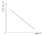
- the graph which shows the relationship between an engine speed and a 1st correction coefficient.
- the graph which shows the relationship between an intake pressure and a 2nd correction coefficient.
- the graph which shows the relationship between an engine speed and a 1st correction value.
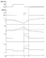
- 6 is a timing chart showing an example of the fuel injection amount and the change in the air-fuel ratio of the air-fuel mixture when restarting the internal combustion engine in a transient state.
- FIG. 1 in an internal combustion engine 10 mounted on a vehicle, four cylinders # 1, # 2, # 3, and # 4 arranged in series have intake air in these cylinders # 1 to # 4. And an exhaust pipe 12 through which exhaust gas is exhausted from the cylinders # 1 to # 4 are connected.
- Each of the intake pipe 11 and the exhaust pipe 12 branches corresponding to the cylinders # 1 to # 4.
- the intake pipe 11 is provided upstream of the branch point with a throttle valve 13 for adjusting the inflow air amount and an air flow meter 14 for measuring the inflow air amount.
- a fuel injection valve 16 for injecting fuel in the delivery pipe 15 is connected to a branched portion of the intake pipe 11. These fuel injection valves 16 inject fuel into the intake ports 19 corresponding to the cylinders # 1 to # 4.
- Each cylinder # 1 to # 4 is provided with a spark plug 24 for igniting the air-fuel mixture.
- the internal combustion engine 10 is provided with a starter 25.
- the starter 25 rotates the engine output shaft 17 using the electric power supplied from the battery 26 when the ignition switch is turned on.
- the starter 25 is a constant mesh starter. Specifically, the pinion gear 20 of the starter 25 always meshes with the ring gear 22 connected to the engine output shaft 17 via the one-way clutch 21.
- the rotational force of the starter 25 is transmitted to the engine output shaft 17 via the one-way clutch 21.
- the one-way clutch 21 is disengaged and the ring gear 22 stops rotating while being engaged with the pinion gear 20 of the starter 25.
- the internal combustion engine 10 and the vehicle on which the engine 10 is mounted are provided with various sensors for detecting the engine operating state and the vehicle running state.
- These sensors include the air flow meter 14, the vehicle speed sensor 27, the coolant temperature sensor 28, the battery current sensor 29, the accelerator operation amount sensor 30, the brake pedal sensor 31, the intake pressure sensor 32, the rotational speed sensor 33, and the cam angle sensor 34.
- the intake pressure sensor 32 is provided downstream of the throttle valve 13 in the intake pipe 11.
- the rotation speed sensor 33 outputs a pulse signal at every predetermined rotation angle of the engine output shaft 17.
- the cam angle sensor 34 outputs a signal corresponding to the rotational phase of a camshaft (not shown) that rotates 1/2 while the engine output shaft 17 rotates once.
- the detection signals of the air flow meter 14 and the sensors 27 to 34 are taken into an electronic control device 35 as a control device.
- the electronic control unit 35 includes an arithmetic processing unit (CPU), a program memory (ROM), a data memory (RAM), and the like, and executes various controls such as control of the fuel injection valve 16 and the starter 25.
- the electronic control unit 35 calculates the engine rotation speed NE based on the output signal from the rotation speed sensor 33. Further, the electronic control unit 35 grasps the crank angle CA based on the output signals from the rotational speed sensor 33 and the cam angle sensor 34 and executes cylinder discrimination, and based on the result, the fuel for the cylinders # 1 to # 4 is determined.
- the engine speed NE and the intake pressure PM are parameters that change in a time-corresponding manner with the change in the flow rate of the intake air. The flow rate of the intake air increases as the engine speed NE increases or the intake pressure PM decreases.
- the electronic control unit 35 also executes control related to so-called economy running in which the operation state of the vehicle on which the internal combustion engine 10 is mounted and the operation of the internal combustion engine 10 are automatically stopped and restarted according to the operation.
- the electronic control unit 35 executes an automatic stop process when the internal combustion engine 10 is in an operating state, for example, when an automatic stop condition for the internal combustion engine 10 is satisfied because the vehicle temporarily stops due to a signal or the like.
- the electronic control unit 35 determines that the automatic stop condition for the internal combustion engine 10 is satisfied when all of these conditions are satisfied based on the detection signals from the sensors 27 to 34.
- Various threshold values used for determining whether or not the automatic stop condition is satisfied are obtained in advance by experiments or the like, and are stored in a program memory (ROM) included in the electronic control unit 35.
- the meshing starter 25 When the restart condition is satisfied, the meshing starter 25 is always driven, and accordingly, the engine output shaft 17 is rotated and the internal combustion engine 10 is restarted. Thereafter, when the internal combustion engine 10 starts autonomous operation through restart by the starter 25, the rotation of the starter 25 is stopped and the drive is ended.
- the electronic control unit 35 can reduce the fuel consumption of the internal combustion engine 10 by automatically stopping and restarting the engine operation in accordance with the operation state or vehicle operation of the internal combustion engine 10 or the vehicle.
- the internal combustion engine 10 is completely stopped, that is, the restart condition is satisfied without taking sufficient time to stop the rotation of the engine output shaft, etc.
- the engine is restarted before the engine is stopped.
- the engine rotational speed of the internal combustion engine 10 is within a range that can be restored to autonomous operation, that is, the fuel injection and ignition corresponding to the engine operating state are resumed without applying the rotational force to the engine output shaft 17 by the starter 25. If the autonomous operation can be resumed by doing this, the internal combustion engine 10 is returned to the autonomous operation without driving the starter 25.
- This restart process is executed on condition that the engine speed NE is equal to or less than a predetermined value A when the restart condition is satisfied.
- step S10 the electronic control unit 35 performs a process of determining whether or not the internal combustion engine 10 is completely stopped, that is, whether or not the engine output shaft 17 is not rotating. At this time, the electronic control unit 35 determines that the internal combustion engine 10 has completely stopped if no signal is input to the electronic control unit 35 from the rotation speed sensor 33 in step S10 (YES in step S10). On the other hand, if a signal is input from rotation speed sensor 33 to electronic control device 35 at predetermined intervals, it is determined that internal combustion engine 10 is in a transient state (NO in step S10).
- step S11 the electronic control unit 35 determines that the engine output shaft 17 is completely stopped.
- the electronic control unit 35 proceeds to step S11 and stops the internal combustion engine 10 based on detection signals from the rotational speed sensor 33 and the cam angle sensor 34.
- Is stored that is, the crank angle CA when the engine output shaft 17 is stopped is stored.
- the electronic control unit 35 calculates the fuel injection amount Qs according to the crank angle CA (step S12).
- the first map in which the relationship between the crank angle CA and the starting basic injection amount Q is referred to is referred to, and the latest crank angle at which fuel can be injected based on the crank angle CA stored in step S11. Is determined, and the starting basic injection amount Q is calculated based on the crank angle.
- the electronic control unit 35 sets the calculated basic injection amount Q at start to the fuel injection amount Qs, and then proceeds to step S13.
- the electronic control unit 35 selects fixed ignition timing setting control that sets the fixed ignition timing regardless of the engine operating state such as the engine speed NE as the ignition timing control mode (step S13).
- step S14 cylinders # 1 to # 4 for which fuel injection is performed first are specified by performing cylinder discrimination, and fuel injection is performed at a predetermined time.
- step S14 the amount of fuel calculated in step S12 is injected.
- step S15 the fixed ignition timing setting control selected in step S13 is executed, and ignition is executed when a predetermined fixed ignition timing is reached.
- the fixed ignition timing is set to be retarded from the ignition timing during steady operation in order to reduce vibration at the time of starting.
- the restart process is temporarily ended. Note that the starter 25 is also driven at a predetermined time with the start of execution of the restart process.
- step S10 determines whether the engine output shaft 17 is rotating and the internal combustion engine 10 is in a transient state. If it is determined in step S10 that the engine output shaft 17 is rotating and the internal combustion engine 10 is in a transient state, the process proceeds to step S16 to detect the crank angle CA. Then, the process proceeds to step S17, and the nearest crank angle at which fuel can be injected is obtained based on the crank angle CA, and the fuel injection amount Qs corresponding to the crank angle, the engine rotational speed NE, and the intake pressure PM is calculated. .
- the above-described first map is referred to, and the starting basic injection amount Q corresponding to the crank angle CA is calculated.
- the starting basic injection amount Q is set in consideration of the amount of adhesion to the wall surface of the intake pipe 11. Further, the second map shown in FIG.
- the first correction coefficient K1 corresponding to the engine speed NE is calculated.
- the third correction coefficient K2 corresponding to the intake pressure PM is calculated with reference to the third map shown in FIG. Then, the fuel injection amount Qs is calculated from the following equation (1).
- the first correction coefficient K1 in the second map is set so as to satisfy the condition of 0 ⁇ K1 ⁇ 1 and to become smaller as the engine speed NE becomes higher. This is because the higher the engine rotational speed NE is, the larger the flow rate of the intake air is, and the amount of wall surface adhesion described above is reduced to secure fuel that contributes to combustion. Therefore, the first correction coefficient increases as the engine rotational speed NE increases. K1 is set to be small.
- the second correction coefficient K2 in the third map is set so as to satisfy the condition of 0 ⁇ K2 ⁇ 1 and become smaller as the intake pressure PM becomes lower. This is because, as the intake pressure PM is lower, the flow rate of the intake air is larger, and the amount of wall surface adhesion described above is reduced to secure fuel that contributes to combustion. Therefore, the second correction coefficient K2 becomes smaller as the intake pressure PM becomes lower. It is set to be smaller.
- step S17 the fuel injection amount Qs calculated in step S17 is decreased as the engine rotational speed NE is increased, and is decreased as the intake pressure PM is decreased.
- the process performed in step S17 is a process performed by the weight reduction correction unit of the electronic control device 35.
- step S18 the electronic control unit 35 selects ignition timing variable setting control for changing the ignition timing in accordance with the engine speed NE and the intake pressure PM as the ignition timing control mode. Thereafter, the process proceeds to step S14, where the electronic control unit 35 performs cylinder discrimination based on the crank angle CA detected in step S16, identifies cylinders # 1 to # 4 that perform fuel injection first, and identifies them. Fuel injection is executed for cylinders # 1 to # 4. At this time, the amount of fuel calculated in step S17 is injected into the identified cylinders # 1 to # 4.
- step S15 the ignition timing variable setting control is executed to set the start timing fire timing according to the engine speed NE and the intake pressure PM.
- control is performed so that the ignition timing is at least advanced with respect to the fixed ignition timing.
- the first correction value KL1 corresponding to the engine speed NE is calculated with reference to the fourth map shown in FIG.
- the second correction value KL2 corresponding to the intake pressure PM is calculated with reference to the fifth map shown in FIG.
- the first correction value KL1 in the fourth map is set to increase as the engine speed NE increases.
- the second correction value KL2 in the fifth map is set so as to increase as the intake pressure PM decreases.
- the first correction value KL1 and the second correction value KL2 are subtracted from the calculated start timing fire timing to correct the start timing fire timing to the advance side.
- the advance angle correction amount with respect to the start timing fire timing is set to be larger as the engine speed NE is higher.
- the advance angle correction amount with respect to the start ignition timing is set to be larger as the intake pressure PM is lower. Therefore, by executing the ignition timing variable setting control, it is possible to achieve the starting ignition timing at which a large engine output can be obtained while avoiding the occurrence of knocking. Note that the processing performed in step S15 when the internal combustion engine 10 is in a transient state is processing performed by the ignition timing correction unit of the electronic control device 35.
- FIG. 7 illustrates various engine states in the case where the restart condition is satisfied and the restart is performed when the internal combustion engine 10 is in a transient state.
- the fuel injection is stopped when the automatic stop condition is satisfied at time t1 from the state in which the internal combustion engine 10 is operating autonomously. Then, after time t1, the engine rotational speed NE decreases and the intake pressure PM increases. Thereafter, at time t2, since the depression of the brake pedal is released, the automatic stop condition is not satisfied and the restart condition is satisfied. Although the engine speed NE at this time does not reach “0” but is smaller than the predetermined value A, the internal combustion engine 10 cannot return to autonomous operation only by restarting fuel injection. Therefore, when the restart condition is satisfied at time t2, the starter 25 is driven, and the rotation of the engine output shaft 17 is assisted.
- the fuel injection amount Qs is reduced accordingly. Therefore, from time t2 to time t3, the fuel injection amount Qs indicated by the solid line in FIG. 7 is smaller than the fuel injection amount at the time of normal start indicated by the two-dot chain line in FIG. If the same amount of fuel is injected from the time t2 to the time t3 as in the case of starting from the engine stop state, the air-fuel mixture in the cylinders # 1 to # 4 is in an over-rich state as indicated by a two-dot chain line in FIG.
- the basic injection amount Q at start-up is corrected to decrease based on the engine rotational speed NE and the intake pressure PM that change in time and correlate with the change in the flow velocity of the intake air.
- the calculated fuel injection amount Qs is adapted to the flow velocity of the intake air flowing downstream of the intake pipe 11. Therefore, even when starting the internal combustion engine 10 in a transient state, the air-fuel ratio of the air-fuel mixture is in the vicinity of the stoichiometric ratio as shown by the solid line in FIG.
- This embodiment has the following advantages. (1) When starting the internal combustion engine 10 in a transient state with the starter 25, the electronic control unit 35 calculates the fuel injection amount Qs at the start based on the engine rotational speed NE and the intake pressure PM. At this time, the electronic control unit 35 corrects the starting basic injection amount Q so as to decrease as the engine speed NE increases or the intake pressure PM decreases. Therefore, even when the internal combustion engine 10 is in a transient state at the start and air flows in the intake pipe 11 and the cylinders # 1 to # 4, the amount of fuel mixed with the intake air is less than the intake air amount. It can be suppressed that the air-fuel mixture becomes excessively rich due to being excessive. That is, when starting the internal combustion engine 10 in a transient state, it is possible to suppress the deterioration of exhaust properties.
- the air flow meter 14 is provided near the upstream side of the intake pipe 11, when detecting the flow velocity of the intake air sucked into the cylinders # 1 to # 4 based on the measurement result by the air flow meter 14, the air flow meter Due to the time during which the intake air flows from 14 to the intake port, the detection accuracy is lowered. In particular, the lower the engine speed NE, the longer the time it takes for the intake air to reach the intake port from the air flow meter 14, so that the detection accuracy of the flow rate of the intake air is significantly reduced in the transient state of the internal combustion engine 10.
- the electronic control unit 35 in the present embodiment is based on the engine starting speed based on the engine rotational speed NE and the intake pressure PM that change in time and correlate with the change in the flow rate of the intake air.
- the injection amount Q is corrected to decrease. Therefore, in the present embodiment, even when the internal combustion engine 10 in a transient state is started, the fuel injection amount Qs is sucked more than when the flow rate of the intake air is detected from the measurement result of the air flow meter 14 and the reduction is corrected. Reduced weight can be corrected to match the air flow rate accurately.
- the electronic control unit 35 injects fuel into the intake port 19 by the fuel injection valve 16 when the internal combustion engine 10 is started.
- fuel is injected into the intake port 19
- a part of the fuel adheres to the wall surface in the intake pipe 11 before being introduced into the cylinders # 1 to # 4.
- the amount of wall surface adhesion tends to be larger than when fuel is directly injected into the inside.
- the fluctuation range of the wall surface adhering amount that changes in accordance with the flow velocity of the intake air also increases as compared with the case where fuel is directly injected into the cylinders # 1 to # 4, and the air-fuel mixture may become overrich.
- the embodiment described above can also be implemented in a form appropriately changed as follows.
- the starting basic injection amount Q is corrected to decrease based on both the intake pressure PM and the engine rotational speed NE.
- the fuel injection amount is decreased based on either the intake pressure PM or the engine rotational speed NE. It may be corrected. That is, the starting basic injection amount Q may be corrected to be reduced by using a correction value based on the engine speed NE without considering the intake pressure PM, or the intake pressure without considering the engine speed NE.
- the starting basic injection amount Q may be corrected to decrease by using a correction value based on PM. And even if it is a case where fuel injection quantity is calculated by performing such reduction
- the reduction correction value when correcting the basic injection amount Q at start-up may be a fixed value. That is, instead of performing the reduction correction according to the intake pressure PM and the engine speed NE, a predetermined reduction correction value may be subtracted from the starting basic injection quantity Q to obtain the fuel injection quantity Qs. Even if the reduction correction value is set to a fixed value in this way, the fuel injection amount Qs can be reduced compared to the fuel injection amount when the engine output shaft 17 is completely restarted. Therefore, it is possible to suppress the deterioration of exhaust properties when starting the internal combustion engine 10 in a transient state.
- the starting basic injection amount Q may be set to a fixed value without changing the starting basic injection amount Q in accordance with the crank angle CA.
- the fuel injection amount Qs calculated at that time may be a fixed value. That is, instead of calculating the starting basic injection amount Q according to the crank angle CA, a predetermined fixed value may be set as the starting basic injection amount Q.
- the control for correcting the ignition timing at the starting time to the advance side is executed based on both the engine speed NE and the intake pressure PM. For example, either one of the engine speed NE and the intake pressure PM is executed.
- ignition timing variable setting control for correcting the starting ignition timing to the advance side may be performed.
- the ignition timing may be advanced by using a correction value based on the engine speed NE without considering the intake pressure PM, or the intake pressure PM without considering the engine speed NE.
- the starting ignition timing may be advanced using a correction value based on the above. Even when the ignition timing at the starting time is corrected in this way, it is possible to suppress a decrease in engine output when starting the internal combustion engine 10 in a transient state.
- the ignition timing may be corrected by setting the advance correction amount as a fixed value without considering parameters such as the engine speed NE and the intake pressure PM.
- the present invention may be applied not only to the internal combustion engine 10 that performs port injection at the start, but also to the internal combustion engine 10 that performs in-cylinder injection at the start.
- the automatic stop and restart conditions of the internal combustion engine 10 are not limited to the conditions exemplified in the embodiment. For example, if the restart condition is satisfied when a key start operation is performed, the restart is executed. Good.
- SYMBOLS 10 Internal combustion engine, 16 ... Fuel injection valve, 17 ... Engine output shaft, 25 ... Starter, 32 ... Intake pressure sensor, 33 ... Rotational speed sensor, 35 ... Electronic control device as a control device.
Landscapes
- Engineering & Computer Science (AREA)
- Chemical & Material Sciences (AREA)
- Combustion & Propulsion (AREA)
- Mechanical Engineering (AREA)
- General Engineering & Computer Science (AREA)
- Electrical Control Of Air Or Fuel Supplied To Internal-Combustion Engine (AREA)
- Control Of Vehicle Engines Or Engines For Specific Uses (AREA)
- Electrical Control Of Ignition Timing (AREA)
- Output Control And Ontrol Of Special Type Engine (AREA)
Abstract
内燃機関の制御装置が開示される。制御装置は、機関出力軸と常時噛み合い式のスタータと燃料噴射弁と減量補正部とを備える。制御装置は、自動停止条件の成立後に再始動条件の成立に基づき機関の運転を再開するとき、前記機関出力軸の回転が機関を自律運転に復帰させることが不可能な速度にまで低下したものの完全に停止していない過渡状態に前記機関がある場合には、前記スタータを用いて前記機関出力軸を回転駆動するとともに前記燃料噴射弁による燃料噴射を再開する。減量補正部は、前記再始動条件が成立したときに内燃機関が前記過渡状態にある場合には前記出力軸の回転が完全に停止した場合と比較して機関運転再開時の始動時燃料噴射量を減量補正する。
Description
本発明は、自動停止条件の成立に基づいて機関運転を停止させる一方、再始動条件の成立に基づいて内燃機関を始動させる内燃機関の制御装置に関する。
内燃機関の制御装置としては、例えば、所定の条件が成立した場合に内燃機関の運転を自動的に停止させ、また、前記条件が不成立になった場合、すなわち再始動条件が成立した場合に再び内燃機関を始動させる、自動停止及び再始動機能を有するものが知られている。こうした内燃機関の制御装置として、特許文献1には、車両の走行速度が所定以下であること、及び運転者によりブレーキペダルが踏まれていること等の条件が成立したとき、内燃機関の自動停止条件が成立したと判断するものが記載されている。特許文献1の内燃機関の制御装置では、自動停止条件が成立したという判断のもとに燃料噴射を停止して、内燃機関を自動停止させる。その後、同制御装置は、ブレーキペダルが踏まれていないことを検出すると、内燃機関の再始動条件が成立したと判断し、スタータを駆動するとともに燃料噴射を再開して内燃機関を始動させる。なお、こうした再始動時においては噴射燃料の一部が吸気通路や燃焼室の壁面に付着すること(壁面付着)を見込んで燃料噴射量が増量されている。
ところで、一般的なスタータとしては、非駆動時にはスタータのピニオンギヤと機関出力軸に組み付けられたリングギヤとが噛み合っておらず、駆動時にだけピニオンギヤがリングギヤに噛み合って機関出力軸に回転力を伝達するものが挙げられる。一方、上述した自動始動及び再始動機能を有する内燃機関では、特許文献2に記載されるような常時噛み合い式のスタータが採用される場合が多い。常時噛み合い式のスタータでは、そのピニオンギヤとリングギヤとが常に噛み合った状態にあり、始動時には係合状態となったワンウェイクラッチを介してリングギヤから機関出力軸に回転力が伝達される。そして、内燃機関が自律運転の可能な状態に移行し、機関出力軸の回転速度がリングギヤの回転速度を上回るようになるとワンウェイクラッチが解放状態となり、スタータによるリングギヤの駆動が停止される。その後は、ワンウェイクラッチが解放状態に維持されるため、リングギヤの回転が停止した状態のままで機関出力軸が回転するようになる。こうした内燃機関のスタータとして常時噛み合い式のスタータを採用した場合には一般的なスタータを採用した場合に比べて機関始動に要する時間を短縮することができる。
ところで、特許文献2に記載された装置のように、内燃機関の自動停止及び再始動を行う場合には、内燃機関が過渡状態にあるとき、すなわち機関出力軸の回転がスタータによる補助がなければ自律運転に復帰できない速度に達したものの完全に停止していないときに再始動が実行されることも考えられる。そして、このときの再始動でも、機関出力軸が完全に停止している状態の内燃機関をスタータによって始動する場合と同様に、上述したような燃料噴射量の増量が行われる。ところがこの場合、内燃機関の吸気系及び燃焼室には吸入空気の流れが生じており、その流れによって燃焼室に流入する噴射燃料の量が多くなるため、機関出力軸の回転が完全に停止したときと比較して壁面付着量が減少するようになる。その結果、過渡状態の内燃機関を再始動する際には、混合気がオーバーリッチ状態となって排気性状の悪化を招くおそれがある。
本発明の目的は、過渡状態の内燃機関を再始動する際に、このときの排気性状の悪化を抑制できる内燃機関の制御装置を提供することにある。
上記目的を達成するため、本発明の態様では、内燃機関の制御装置が提供される。制御装置は、出力軸と常時噛み合い式のスタータと燃料噴射弁と減量補正部とを備える。制御装置は、自動停止条件の成立に基づいて前記機関の運転を停止する一方、再始動条件の成立に基づいて前記機関の運転を再開する。制御装置は、前記自動停止条件の成立後に前記再始動条件の成立に基づき機関の運転を再開するとき、前記出力軸の回転が機関を自律運転に復帰させることが不可能な速度にまで低下したものの完全に停止していない過渡状態に前記機関がある場合には、前記スタータを用いて前記出力軸を回転駆動するとともに前記燃料噴射弁による燃料噴射を再開する。減量補正部は、前記再始動条件が成立したときに内燃機関が前記過渡状態にある場合には前記出力軸の回転が完全に停止した場合と比較して機関運転再開時の始動時燃料噴射量を減量補正する。
上記目的を達成するため、本発明の態様では、内燃機関の制御装置が提供される。制御装置は、出力軸と常時噛み合い式のスタータと燃料噴射弁と減量補正部とを備える。制御装置は、自動停止条件の成立に基づいて前記機関の運転を停止する一方、再始動条件の成立に基づいて前記機関の運転を再開する。制御装置は、前記自動停止条件の成立後に前記再始動条件の成立に基づき機関の運転を再開するとき、前記出力軸の回転が機関を自律運転に復帰させることが不可能な速度にまで低下したものの完全に停止していない過渡状態に前記機関がある場合には、前記スタータを用いて前記出力軸を回転駆動するとともに前記燃料噴射弁による燃料噴射を再開する。減量補正部は、前記再始動条件が成立したときに内燃機関が前記過渡状態にある場合には前記出力軸の回転が完全に停止した場合と比較して機関運転再開時の始動時燃料噴射量を減量補正する。
以下、本発明の一実施形態について、図1~図7を参照して説明する。
図1に示すように、車両に搭載される内燃機関10において、その直列に配列された4つのシリンダ#1,#2,#3,#4には、これらシリンダ#1~#4に吸入空気を供給する吸気管11、及び同シリンダ#1~#4から排気が排出される排気管12がそれぞれ接続されている。これら吸気管11及び排気管12の各々は、シリンダ#1~#4にそれぞれ対応して分岐している。吸気管11にはこの分岐点よりも上流に、その流入空気量を調量するスロットルバルブ13と、同流入空気量を計測するエアフローメータ14とが設けられている。また、吸気管11における分岐した部分には、デリバリパイプ15内の燃料を噴射するための燃料噴射弁16がそれぞれ接続されている。これら燃料噴射弁16はシリンダ#1~#4に対応する吸気ポート19に燃料を噴射する。また、各シリンダ#1~#4には混合気に着火するための点火プラグ24が設けられている。
図1に示すように、車両に搭載される内燃機関10において、その直列に配列された4つのシリンダ#1,#2,#3,#4には、これらシリンダ#1~#4に吸入空気を供給する吸気管11、及び同シリンダ#1~#4から排気が排出される排気管12がそれぞれ接続されている。これら吸気管11及び排気管12の各々は、シリンダ#1~#4にそれぞれ対応して分岐している。吸気管11にはこの分岐点よりも上流に、その流入空気量を調量するスロットルバルブ13と、同流入空気量を計測するエアフローメータ14とが設けられている。また、吸気管11における分岐した部分には、デリバリパイプ15内の燃料を噴射するための燃料噴射弁16がそれぞれ接続されている。これら燃料噴射弁16はシリンダ#1~#4に対応する吸気ポート19に燃料を噴射する。また、各シリンダ#1~#4には混合気に着火するための点火プラグ24が設けられている。
また、内燃機関10には、スタータ25が設けられている。このスタータ25は、内燃機関10の運転が停止している場合、イグニッションスイッチがオンされたことを契機に、バッテリ26から供給される電力を用いて機関出力軸17を回転させる。このスタータ25は、常時噛み合い式のスタータである。具体的には、スタータ25のピニオンギヤ20は、ワンウェイクラッチ21を介して機関出力軸17に連結されたリングギヤ22と常に噛み合っている。内燃機関10の始動時には、スタータ25の回転力がワンウェイクラッチ21を介して機関出力軸17に伝達される。一方、機関運転中には、ワンウェイクラッチ21が解放状態となりリングギヤ22はスタータ25のピニオンギヤ20と噛み合った状態のままその回転が停止している。
図1に示されるように、内燃機関10や該機関10が搭載される車両には、機関運転状態や車両走行状態を検出する各種センサが設けられている。これらセンサには、上述したエアフローメータ14、車速センサ27、冷却水温センサ28、バッテリ電流センサ29、アクセラレータ操作量センサ30、ブレーキペダルセンサ31、吸気圧センサ32、回転速度センサ33、カム角センサ34が含まれる。吸気圧センサ32は吸気管11においてスロットルバルブ13よりも下流に設けられている。回転速度センサ33は機関出力軸17の所定回転角毎にパルス信号を出力する。カム角センサ34は機関出力軸17が一回転する間に1/2回転するカムシャフト(図示略)の回転位相に対応した信号を出力する。そして、これらエアフローメータ14及びセンサ27~34の検出信号は制御装置としての電子制御装置35に取り込まれる。
電子制御装置35は、演算処理装置(CPU)やプログラムメモリ(ROM)、データメモリ(RAM)等を有し、燃料噴射弁16やスタータ25の制御等、各種制御を実行する。電子制御装置35は回転速度センサ33からの出力信号に基づき機関回転速度NEを算出する。また、電子制御装置35は回転速度センサ33及びカム角センサ34からの出力信号に基づきクランク角CAを把握して気筒判別を実行するとともに、その結果に基づいて各シリンダ#1~#4に対する燃料噴射時期及び点火時期を設定する。機関回転速度NE及び吸気圧PMは、吸入空気の流速の変化と時間的に一致しするように且つ相関的に変化するパラメータである。吸入空気の流速は、機関回転速度NEが高くなるか、若しくは吸気圧PMが低くなるほど増大する。
また、電子制御装置35は、内燃機関10を搭載した車両の運転状態や、その操作に応じて内燃機関10の運転を自動的に停止及び再始動させる、いわゆるエコノミーランニングに係る制御も実行する。
次に、このエコノミーランニングに係る制御について以下に説明する。電子制御装置35は、内燃機関10が運転状態にあるときに、例えば、信号待ち等で車両が一時的に停止したことによって内燃機関10の自動停止条件が成立すると、自動停止処理を実行する。
上記自動停止条件としては、
・アクセラレータ操作量が「0」であること(アクセルペダルが踏み込まれていないこと)
・車両の走行速度が所定速度以下であること
・ブレーキペダルが踏み込まれていること
・機関冷却水の温度が所定温度以上であること
・バッテリ26の充電量が所定値以上であること
等が挙げられる。とくに、本実施形態においては、電子制御装置35が各センサ27~34からの検出信号に基づいてこうした条件が全て成立したときに、内燃機関10の自動停止条件が成立したと判断する。なお、自動停止条件の成立判断に用いられる各種閾値は、予め実験等によって求められ、電子制御装置35が備えるプログラムメモリ(ROM)に記憶されている。
・アクセラレータ操作量が「0」であること(アクセルペダルが踏み込まれていないこと)
・車両の走行速度が所定速度以下であること
・ブレーキペダルが踏み込まれていること
・機関冷却水の温度が所定温度以上であること
・バッテリ26の充電量が所定値以上であること
等が挙げられる。とくに、本実施形態においては、電子制御装置35が各センサ27~34からの検出信号に基づいてこうした条件が全て成立したときに、内燃機関10の自動停止条件が成立したと判断する。なお、自動停止条件の成立判断に用いられる各種閾値は、予め実験等によって求められ、電子制御装置35が備えるプログラムメモリ(ROM)に記憶されている。
自動停止処理が実行されると、燃料噴射弁16によるシリンダ#1~#4内に対する燃料噴射及び点火プラグ24による点火が停止され、機関運転が停止される。
他方、機関運転が停止しているときに、内燃機関10を再始動させる条件が成立すると内燃機関10を始動する。この再始動条件としては、
・ブレーキペダルが踏み込まれていないこと
・アクセルペダルの操作量が「0」でないこと
・バッテリ26の充電量が所定値未満に低下したこと
等が挙げられ、本実施形態においては、各センサ27~34の検出信号に基づいて電子制御装置35がこうした条件のいずれかが成立したと判断したときに、内燃機関10の再始動条件が成立したと判断する。
他方、機関運転が停止しているときに、内燃機関10を再始動させる条件が成立すると内燃機関10を始動する。この再始動条件としては、
・ブレーキペダルが踏み込まれていないこと
・アクセルペダルの操作量が「0」でないこと
・バッテリ26の充電量が所定値未満に低下したこと
等が挙げられ、本実施形態においては、各センサ27~34の検出信号に基づいて電子制御装置35がこうした条件のいずれかが成立したと判断したときに、内燃機関10の再始動条件が成立したと判断する。
再始動条件が成立すると、常時噛み合い式のスタータ25が駆動され、これに伴い機関出力軸17が回転されて内燃機関10が再始動される。その後、スタータ25による再始動を経て内燃機関10が自律運転を開始すると、スタータ25の回転が停止されてその駆動を終了する。このように電子制御装置35は、内燃機関10あるいは車両の運転状態や車両操作に応じて、機関運転を自動停止及び再始動させることで、内燃機関10の燃料消費量の低減を可能としている。
ところで、自動停止条件が成立して自動停止処理が実行されても、例えば内燃機関が完全停止、すなわち機関出力軸の回転が停止するのに足るだけの時間をおかずに再始動条件が成立する等して、機関停止状態になる前に機関を再始動する場合がある。このとき、内燃機関10の機関回転速度が自律運転に復帰可能な範囲であれば、すなわちスタータ25によって機関出力軸17に回転力を付与しなくとも機関運転状態に応じた燃料噴射及び点火を再開することにより自律運転を再開することができるのであれば、スタータ25を駆動せずに内燃機関10を自律運転に復帰させる。機関出力軸17の回転が自律運転に復帰できない速度にまで低下しているときには、内燃機関10が過渡状態にあると判断して再始動処理を実行し、スタータ25を駆動するとともに始動時の燃料噴射量を制御する。
以下に、電子制御装置35にて実行されるこうした再始動処理の手順について図2を参照して説明する。なお、この再始動処理は、再始動条件が成立したときに、機関回転速度NEが所定値A以下であることを条件として実行される。
まず、電子制御装置35は、ステップS10において、内燃機関10が完全に停止しているか否か、すなわち機関出力軸17が回転していないか否かを判断する処理を行う。このとき、電子制御装置35は、ステップS10において、回転速度センサ33から同電子制御装置35に所定期間信号が入力されなければ、内燃機関10が完全に停止したと判断する(ステップS10においてYES)一方、回転速度センサ33から所定間隔で信号が同電子制御装置35に入力されていれば内燃機関10が過渡状態であると判断する(ステップS10においてNO)。電子制御装置35は、機関出力軸17が完全に停止していると判断すると、ステップS11に移行して、回転速度センサ33及びカム角センサ34による検出信号に基づいて、内燃機関10が停止している位置、すなわち機関出力軸17が停止したときのクランク角CAを記憶する。そして、電子制御装置35はクランク角CAに応じた燃料噴射量Qsを算出する(ステップS12)。具体的には、クランク角CAと始動時基本噴射量Qとの関係が対応付けられた第1マップが参照され、ステップS11で記憶したクランク角CAに基づいて燃料を噴射可能な直近のクランク角を決定するとともにそのクランク角に基づいて始動時基本噴射量Qが算出される。電子制御装置35は、算出した始動時基本噴射量Qを燃料噴射量Qsとした後、ステップS13に移行する。電子制御装置35は、点火時期制御モードとして、機関回転速度NE等の機関運転状態とは無関係に固定点火時期を設定する固定点火時期設定制御を選択する(ステップS13)。
次に、ステップS14では、気筒判別を行って初めに燃料噴射を行うシリンダ#1~#4を特定し、所定の時期に燃料噴射を行う。ステップS14では、ステップS12で算出した量の燃料が噴射される。ステップS15においては、ステップS13において選択された固定点火時期設定制御を実行し、所定の固定点火時期に至ると点火を実行する。固定点火時期は、始動時の振動を低減するため、定常運転時の点火時期よりも遅角側に設定されている。ステップS15の処理が終了すると、再始動処理が一旦終了する。なお、再始動処理の実行開始に伴って、所定の時期にスタータ25も駆動される。
一方、ステップS10において、機関出力軸17が回転しており内燃機関10が過渡状態にあると判断すると、ステップS16に移行して、クランク角CAを検出する。そして、ステップS17に移行して、そのクランク角CAに基づいて燃料を噴射可能な直近のクランク角を求め、同クランク角、機関回転速度NE、吸気圧PMに応じた燃料噴射量Qsを算出する。この処理では、前述の第1マップが参照され、クランク角CAに応じた始動時基本噴射量Qが算出される。始動時基本噴射量Qは、吸気管11の壁面に対する付着分を見込んで設定される。また、図3に示す第2マップが参照され、機関回転速度NEに応じた第1補正係数K1が算出される。さらに、図4に示す第3マップが参照され、吸気圧PMに応じた第2補正係数K2が算出される。そして、下式(1)から燃料噴射量Qsが算出される。
Qs=Q・K1・K2・・・(1)
図3に示すように、第2マップにおける第1補正係数K1は、0<K1<1という条件を満たし、かつ機関回転速度NEが高くなるほど小さくなるように設定されている。これは、機関回転速度NEが高いときほど吸入空気の流速が大きくなり、上述した壁面付着量が減少して燃焼に寄与する燃料が確保されるため、機関回転速度NEが高くなるほど第1補正係数K1は小さくなるように設定されている。
図3に示すように、第2マップにおける第1補正係数K1は、0<K1<1という条件を満たし、かつ機関回転速度NEが高くなるほど小さくなるように設定されている。これは、機関回転速度NEが高いときほど吸入空気の流速が大きくなり、上述した壁面付着量が減少して燃焼に寄与する燃料が確保されるため、機関回転速度NEが高くなるほど第1補正係数K1は小さくなるように設定されている。
また、図4に示すように、第3マップにおける第2補正係数K2は、0<K2<1という条件を満たし、かつ吸気圧PMが低くなるほど小さくなるように設定されている。これは、吸気圧PMが低いときほど吸入空気の流速が大きくなり、上述した壁面付着量が減少して燃焼に寄与する燃料が確保されるため、吸気圧PMが低くなるほど第2補正係数K2は小さくなるように設定されている。
そのため、ステップS17において算出される燃料噴射量Qsは、機関回転速度NEが高くなるほど減量されるとともに、吸気圧PMが低くなるほど減量される。なお、内燃機関10が過渡状態にある場合、ステップS17で行われる処理は、電子制御装置35の減量補正部が行う処理である。
次に、ステップS18に移行すると、電子制御装置35は、点火時期制御モードとして、機関回転速度NE及び吸気圧PMに応じて点火時期を変更する点火時期可変設定制御を選択する。その後、ステップS14に移行して、電子制御装置35はステップS16で検出したクランク角CAに基づいて気筒判別を行い、燃料噴射を初めに行うシリンダ#1~#4を特定し、その特定されたシリンダ#1~#4に対して燃料噴射を実行する。このとき、ステップS17で算出した量の燃料が、特定されたシリンダ#1~#4に噴射される。
次に、ステップS15では、点火時期可変設定制御を実行することで、機関回転速度NE及び吸気圧PMに応じた始動時点火時期を設定する。この点火時期可変設定制御では、点火時期が少なくとも固定点火時期よりも進角側となるように制御される。具体的には、図5に示す第4マップを参照して、機関回転速度NEに応じた第1補正値KL1を算出する。また、図6に示す第5マップを参照して、吸気圧PMに応じた第2補正値KL2を算出する。第4マップにおける第1補正値KL1は、機関回転速度NEが高くなるほど大きくなるように設定されている。また、第5マップにおける第2補正値KL2は、吸気圧PMが低くなるほど大きくなるように設定されている。これは、機関回転速度NEが高いときほど、若しくは吸気圧PMが低いときほど点火時期を進角側にしなければ、混合気が燃焼してシリンダ#1~#4内で火炎伝播の広がる時期が圧縮行程の上死点よりも後になってしまうためである。
そして、点火時期可変設定制御が実行されたとき、算出された始動時点火時期に対して第1補正値KL1及び第2補正値KL2を減算して、始動時点火時期を進角側に補正する。本実施形態の点火時期可変設定制御では、機関回転速度NEが高くなるほど始動時点火時期に対する進角補正量が大きくなるように設定される。また、点火時期可変設定制御では、吸気圧PMが低くなるほど、始動点火時期に対する進角補正量が大きくなるように設定される。そのため、点火時期可変設定制御を実行することで、ノッキングの発生を回避しつつ大きな機関出力が得られる始動時点火時期にすることができる。なお、内燃機関10が過渡状態である場合にステップS15で行われる処理は、電子制御装置35の点火時期補正部が行う処理である。
次に、再始動処理を実行した場合の動作例について図7を参照して説明する。図7については、内燃機関10が過渡状態のときに再始動条件が成立し再始動を行う場合における各種機関状態を例示している。
図7に示すように、内燃機関10が自律運転している状態から、時刻t1において自動停止条件が成立すると燃料噴射が停止される。すると、時刻t1以降、機関回転速度NEが低下するとともに、吸気圧PMが上昇する。その後、時刻t2になると、ブレーキペダルの踏み込みが解除されたため、自動停止条件が不成立になるとともに再始動条件が成立する。このときの機関回転速度NEは「0」に至ってはいないものの所定値Aよりも小さいため、燃料噴射を再開するだけでは内燃機関10が自律運転に復帰できない状態になっている。そのため、時刻t2で再始動条件が成立すると、スタータ25が駆動されて、機関出力軸17の回転が補助される。時刻t2から時刻t3の間、機関回転速度NEが増大するとともに吸気圧PMが低下することで、吸入空気の流速(=吸気管11を流通する単位断面積当たりの吸入空気の流量)も大きくなるが、その分、燃料噴射量Qsは減量される。そのため、時刻t2から時刻t3において、図7の実線で示す燃料噴射量Qsは、図7の二点鎖線で示す通常始動時の燃料噴射量よりも減少する。仮に、時刻t2から時刻t3において、機関停止状態から始動する場合と同量の燃料を噴射すると、シリンダ#1~#4内における混合気は図7の二点鎖線で示すようにオーバーリッチ状態になる。しかし、本実施形態では、吸入空気の流速の変化と時間的に一致するように且つ相関的に変化する機関回転速度NE及び吸気圧PMに基づいて始動時基本噴射量Qを減量補正するため、算出された燃料噴射量Qsは吸気管11の下流側を流れる吸入空気の流速に適合している。したがって、過渡状態にある内燃機関10を始動する際においても、図7の実線で示すように混合気の空燃比はストイキ比の付近にある。
なお、時刻t3になると、スタータ25の駆動は停止されるが、このときには機関回転速度NEが所定値Aよりも高くなっているため、時刻t3以降、内燃機関10は自律運転を再開する。
本実施形態は以下の利点を有する。
(1)電子制御装置35は、過渡状態にある内燃機関10をスタータ25によって始動する場合、機関回転速度NE及び吸気圧PMに基づいて始動時の燃料噴射量Qsを算出する。この際、電子制御装置35は、機関回転速度NEが高くなるほど、若しくは吸気圧PMが低くなるほど、始動時基本噴射量Qを減量補正する。したがって、始動時に内燃機関10が過渡状態になっており吸気管11やシリンダ#1~#4内に空気の流れが生じていても、吸入空気と混合される燃料量が吸入空気量に対して過剰になって、混合気がオーバーリッチ状態になることを抑制できる。すなわち、過渡状態の内燃機関10を始動する際に、排気性状が悪化することを抑制できる。
(1)電子制御装置35は、過渡状態にある内燃機関10をスタータ25によって始動する場合、機関回転速度NE及び吸気圧PMに基づいて始動時の燃料噴射量Qsを算出する。この際、電子制御装置35は、機関回転速度NEが高くなるほど、若しくは吸気圧PMが低くなるほど、始動時基本噴射量Qを減量補正する。したがって、始動時に内燃機関10が過渡状態になっており吸気管11やシリンダ#1~#4内に空気の流れが生じていても、吸入空気と混合される燃料量が吸入空気量に対して過剰になって、混合気がオーバーリッチ状態になることを抑制できる。すなわち、過渡状態の内燃機関10を始動する際に、排気性状が悪化することを抑制できる。
また、エアフローメータ14は吸気管11の上流寄りに設けられているため、エアフローメータ14による計測結果に基づいてシリンダ#1~#4内に吸入される吸入空気の流速を検出する場合、エアフローメータ14から吸気ポートまでの間を吸入空気が流通する時間に起因して、検出精度は低くなる。とくに、機関回転速度NEが低いほど吸入空気がエアフローメータ14から吸気ポートに達するまでに要する時間も長くなるため、内燃機関10の過渡状態では、吸入空気の流速の検出精度は顕著に低くなる。これに対して、本実施形態における電子制御装置35は、吸入空気の流速の変化と時間的に一致するように且つ相関的に変化する機関回転速度NE及び吸気圧PMに基づいて、始動時基本噴射量Qを減量補正する。したがって、本実施形態では、過渡状態にある内燃機関10を始動するときであっても、エアフローメータ14の計測結果から吸入空気の流速を検出して減量補正する場合よりも燃料噴射量Qsが吸入空気の流速に精度よく適合するように減量補正できる。
(2)再始動要求時のクランク角CAに基づいて燃料噴射可能な直近のクランク角を求め、同クランク角に基づいて始動時基本噴射量Qを算出するようにしている。したがって、内燃機関10を始動するために過不足ない燃料噴射量Qsにすることができ、燃費を向上させることができる。
(3)内燃機関10が過渡状態になっているときに再始動条件が成立し、スタータ25による始動が行われる場合、点火時期は進角側に補正される。この際、機関回転速度NEが高いほど、若しくは吸気圧PMが低いほど始動時点火時期の進角補正量を大きくする。したがって、通常の機関始動時のように点火時期を遅角側に設定して機関運転を再開する場合に比べて、機関出力の低下を抑制して本来の加速性能を維持することができ、機関回転速度NE及び吸気圧PMに応じた適正な機関出力を得ることができる。
(4)電子制御装置35は、内燃機関10の始動時に燃料噴射弁16によって吸気ポート19内に燃料を噴射する。そして、吸気ポート19内に燃料が噴射されると、その燃料の一部はシリンダ#1~#4内に導入されるまでに吸気管11内の壁面に付着するため、シリンダ#1~#4内に直接燃料を噴射する場合よりも、壁面付着量が多くなる傾向にある。このため、吸入空気の流速に応じて変化する壁面付着量の変動幅もシリンダ#1~#4内に直接燃料を噴射する場合と比較して多くなり、混合気がオーバーリッチ状態となる可能性も高いものとなるが、本実施形態では、混合気がオーバーリッチ状態となることを好適に抑制することができるようになる。
上述した実施の形態は、以下のように適宜変更した形態にて実施することもできる。
始動時基本噴射量Qを吸気圧PM及び機関回転速度NEの双方に基づいて減量補正するようにしたが、例えば、吸気圧PM及び機関回転速度NEのいずれか一方に基づいて燃料噴射量を減量補正してもよい。すなわち、吸気圧PMについては考慮せずに機関回転速度NEに基づいた補正値を用いて始動時基本噴射量Qを減量補正してもよいし、機関回転速度NEについては考慮せずに吸気圧PMに基づいた補正値を用いて始動時基本噴射量Qを減量補正してもよい。そして、このような減量補正を行って燃料噴射量を算出した場合であっても、過渡状態の内燃機関10を始動する際に排気性状が悪化することを抑制できる。
始動時基本噴射量Qを吸気圧PM及び機関回転速度NEの双方に基づいて減量補正するようにしたが、例えば、吸気圧PM及び機関回転速度NEのいずれか一方に基づいて燃料噴射量を減量補正してもよい。すなわち、吸気圧PMについては考慮せずに機関回転速度NEに基づいた補正値を用いて始動時基本噴射量Qを減量補正してもよいし、機関回転速度NEについては考慮せずに吸気圧PMに基づいた補正値を用いて始動時基本噴射量Qを減量補正してもよい。そして、このような減量補正を行って燃料噴射量を算出した場合であっても、過渡状態の内燃機関10を始動する際に排気性状が悪化することを抑制できる。
始動時基本噴射量Qを減量補正する際の減量補正値を固定値にしてもよい。すなわち、吸気圧PMや機関回転速度NEに応じた減量補正を行う代わりに、始動時基本噴射量Qに対して所定の減量補正値を減算して、燃料噴射量Qsとしてもよい。そして、このように減量補正値を固定値にしても、機関出力軸17が完全に停止している状態から再始動する際の燃料噴射量と比較して、燃料噴射量Qsを減量することができるため、過渡状態の内燃機関10を始動する際に排気性状が悪化することを抑制できる。
始動時基本噴射量Qを算出する際、クランク角CAに応じて始動時基本噴射量Qを変更することなく、例えば、始動時基本噴射量Qを固定値にしてもよい。
機関出力軸17が完全に停止している内燃機関10をスタータ25を駆動して再始動する場合において、そのときに算出される燃料噴射量Qsを固定値にしてもよい。すなわち、クランク角CAに応じた始動時基本噴射量Qを算出する代わりに、所定の固定値を始動時基本噴射量Qとして設定してもよい。
機関出力軸17が完全に停止している内燃機関10をスタータ25を駆動して再始動する場合において、そのときに算出される燃料噴射量Qsを固定値にしてもよい。すなわち、クランク角CAに応じた始動時基本噴射量Qを算出する代わりに、所定の固定値を始動時基本噴射量Qとして設定してもよい。
点火時期可変設定制御では機関回転速度NE及び吸気圧PMの双方に基づいて始動時点火時期を進角側に補正する制御を実行したが、例えば、機関回転速度NE及び吸気圧PMのいずれか一方に基づいて始動時点火時期を進角側に補正する点火時期可変設定制御を行うようにしてもよい。すなわち、吸気圧PMについては考慮せずに機関回転速度NEに基づいた補正値を用いて始動時点火時期を進角補正してもよいし、機関回転速度NEについては考慮せずに吸気圧PMに基づいた補正値を用いて始動時点火時期を進角補正してもよい。このようにして始動時点火時期を進角補正した場合であっても、過渡状態の内燃機関10を始動する際に機関出力が低下することを抑制できる。
また、機関回転速度NEや吸気圧PM等のパラメータを考慮せずに、進角補正量を固定値として、始動時点火時期を補正するようにしてもよい。
本発明を、始動時にポート噴射を行う内燃機関10に限らず、始動時に筒内噴射を行う内燃機関10に適用してもよい。
本発明を、始動時にポート噴射を行う内燃機関10に限らず、始動時に筒内噴射を行う内燃機関10に適用してもよい。
内燃機関10の自動停止及び再始動条件は実施形態にて例示した条件に限らず、例えば、キー始動操作が行われた場合に再始動条件が成立したとして、再始動を実行するようにしてもよい。
10…内燃機関、16…燃料噴射弁、17…機関出力軸、25…スタータ、32…吸気圧センサ、33…回転速度センサ、35…制御装置としての電子制御装置。
Claims (7)
- 出力軸と常時噛み合い式のスタータと燃料噴射弁とを備える内燃機関の制御装置であって、自動停止条件の成立に基づいて前記機関の運転を停止する一方、再始動条件の成立に基づいて前記機関の運転を再開し、前記自動停止条件の成立後に前記再始動条件の成立に基づき機関の運転を再開するとき、前記出力軸の回転が機関を自律運転に復帰させることが不可能な速度にまで低下したものの完全に停止していない過渡状態に前記機関がある場合には、前記スタータを用いて前記出力軸を回転駆動するとともに前記燃料噴射弁による燃料噴射を再開する制御装置において、
前記再始動条件が成立したときに内燃機関が前記過渡状態にある場合には前記出力軸の回転が完全に停止した場合と比較して機関運転再開時の始動時燃料噴射量を減量補正する減量補正部を備える、内燃機関の制御装置。 - 前記減量補正部は、前記再始動条件が成立したときの前記出力軸の回転速度が高いときほど始動時燃料噴射量の減量補正量を大きくする、請求項1に記載の内燃機関の制御装置。
- 前記減量補正部は、前記再始動条件が成立したときの吸気圧が低いときほど始動時燃料噴射量の減量補正量を大きくする、請求項1又は請求項2に記載の内燃機関の制御装置。
- 前記再始動条件が成立したときに内燃機関が前記過渡状態にある場合には内燃機関の運転が完全に停止した場合と比較して機関運転再開時の始動時点火時期を進角側に補正する点火時期補正部を備える、請求項1~請求項3のいずれか一項に記載の内燃機関の制御装置。
- 前記点火時期補正部は、前記再始動条件が成立したときの機関回転速度が高いときほど始動時点火時期の補正量を大きく設定する、請求項4に記載の内燃機関の制御装置。
- 前記点火時期補正部は前記再始動条件が成立したときの吸気圧が低いときほど始動時点火時期の補正量を大きく設定する、請求項4又は請求項5に記載の内燃機関の制御装置。
- 前記燃料噴射弁は内燃機関の吸気通路に燃料を噴射するように配置される、請求項1~6のいずれか一項に記載の内燃機関の制御装置。
Priority Applications (2)
| Application Number | Priority Date | Filing Date | Title |
|---|---|---|---|
| CN201180005678.3A CN102725500B (zh) | 2010-01-13 | 2011-01-06 | 内燃机的控制装置 |
| EP11732831.0A EP2525065B1 (en) | 2010-01-13 | 2011-01-06 | Internal combustion engine control device |
Applications Claiming Priority (2)
| Application Number | Priority Date | Filing Date | Title |
|---|---|---|---|
| JP2010005193A JP5381733B2 (ja) | 2010-01-13 | 2010-01-13 | 内燃機関の制御装置 |
| JP2010-005193 | 2010-01-13 |
Publications (1)
| Publication Number | Publication Date |
|---|---|
| WO2011086961A1 true WO2011086961A1 (ja) | 2011-07-21 |
Family
ID=44304234
Family Applications (1)
| Application Number | Title | Priority Date | Filing Date |
|---|---|---|---|
| PCT/JP2011/050084 Ceased WO2011086961A1 (ja) | 2010-01-13 | 2011-01-06 | 内燃機関の制御装置 |
Country Status (4)
| Country | Link |
|---|---|
| EP (1) | EP2525065B1 (ja) |
| JP (1) | JP5381733B2 (ja) |
| CN (1) | CN102725500B (ja) |
| WO (1) | WO2011086961A1 (ja) |
Families Citing this family (5)
| Publication number | Priority date | Publication date | Assignee | Title |
|---|---|---|---|---|
| JP5968771B2 (ja) * | 2012-12-07 | 2016-08-10 | 日立オートモティブシステムズ株式会社 | 内燃機関の燃料噴射制御装置 |
| JP5994801B2 (ja) * | 2014-02-28 | 2016-09-21 | トヨタ自動車株式会社 | 内燃機関の停止始動制御装置 |
| JP6287889B2 (ja) * | 2015-02-19 | 2018-03-07 | トヨタ自動車株式会社 | 多気筒内燃機関の制御装置 |
| JP6418206B2 (ja) * | 2016-08-10 | 2018-11-07 | トヨタ自動車株式会社 | エンジンの始動制御装置 |
| JP7666350B2 (ja) * | 2022-02-09 | 2025-04-22 | トヨタ自動車株式会社 | 車両の制御装置 |
Citations (7)
| Publication number | Priority date | Publication date | Assignee | Title |
|---|---|---|---|---|
| JPS58162738A (ja) * | 1982-03-16 | 1983-09-27 | ロ−ベルト・ボツシユ・ゲゼルシヤフト・ミツト・ベシユレンクテル・ハフツング | 自己点火式内燃機関の電子燃料供給量制御装置 |
| JP2002339781A (ja) * | 2001-05-17 | 2002-11-27 | Toyota Motor Corp | 車両用エンジンの制御装置 |
| JP2003065191A (ja) * | 2001-08-28 | 2003-03-05 | Toyota Motor Corp | 内燃機関の始動制御装置 |
| JP2008223674A (ja) * | 2007-03-14 | 2008-09-25 | Mazda Motor Corp | 手動変速機付き車両用エンジンの自動停止装置 |
| JP2008267297A (ja) * | 2007-04-20 | 2008-11-06 | Fujitsu Ten Ltd | エコラン制御装置及びエンジン再始動方法 |
| JP2009299598A (ja) * | 2008-06-13 | 2009-12-24 | Toyota Motor Corp | エンジンの制御装置 |
| JP2010112354A (ja) * | 2008-11-10 | 2010-05-20 | Toyota Motor Corp | 車載内燃機関の制御装置 |
Family Cites Families (3)
| Publication number | Priority date | Publication date | Assignee | Title |
|---|---|---|---|---|
| JP3571014B2 (ja) * | 2001-08-30 | 2004-09-29 | 本田技研工業株式会社 | 内燃機関の自動停止始動制御装置 |
| JP4589214B2 (ja) * | 2005-01-13 | 2010-12-01 | トヨタ自動車株式会社 | 内燃機関の始動制御装置 |
| DE102007060019B3 (de) * | 2007-12-13 | 2009-04-23 | Continental Automotive Gmbh | Verfahren und Vorrichtung zum Steuern einer Brennkraftmaschine im Stopp/Start-Betrieb |
-
2010
- 2010-01-13 JP JP2010005193A patent/JP5381733B2/ja not_active Expired - Fee Related
-
2011
- 2011-01-06 WO PCT/JP2011/050084 patent/WO2011086961A1/ja not_active Ceased
- 2011-01-06 EP EP11732831.0A patent/EP2525065B1/en not_active Not-in-force
- 2011-01-06 CN CN201180005678.3A patent/CN102725500B/zh not_active Expired - Fee Related
Patent Citations (7)
| Publication number | Priority date | Publication date | Assignee | Title |
|---|---|---|---|---|
| JPS58162738A (ja) * | 1982-03-16 | 1983-09-27 | ロ−ベルト・ボツシユ・ゲゼルシヤフト・ミツト・ベシユレンクテル・ハフツング | 自己点火式内燃機関の電子燃料供給量制御装置 |
| JP2002339781A (ja) * | 2001-05-17 | 2002-11-27 | Toyota Motor Corp | 車両用エンジンの制御装置 |
| JP2003065191A (ja) * | 2001-08-28 | 2003-03-05 | Toyota Motor Corp | 内燃機関の始動制御装置 |
| JP2008223674A (ja) * | 2007-03-14 | 2008-09-25 | Mazda Motor Corp | 手動変速機付き車両用エンジンの自動停止装置 |
| JP2008267297A (ja) * | 2007-04-20 | 2008-11-06 | Fujitsu Ten Ltd | エコラン制御装置及びエンジン再始動方法 |
| JP2009299598A (ja) * | 2008-06-13 | 2009-12-24 | Toyota Motor Corp | エンジンの制御装置 |
| JP2010112354A (ja) * | 2008-11-10 | 2010-05-20 | Toyota Motor Corp | 車載内燃機関の制御装置 |
Also Published As
| Publication number | Publication date |
|---|---|
| EP2525065A1 (en) | 2012-11-21 |
| CN102725500B (zh) | 2016-05-18 |
| EP2525065B1 (en) | 2018-11-28 |
| JP5381733B2 (ja) | 2014-01-08 |
| CN102725500A (zh) | 2012-10-10 |
| JP2011144730A (ja) | 2011-07-28 |
| EP2525065A4 (en) | 2017-07-12 |
Similar Documents
| Publication | Publication Date | Title |
|---|---|---|
| EP2309110B1 (en) | Engine stoppage control device | |
| EP2420663B1 (en) | Automatic stop/start control device for internal combustion engine | |
| JP2002130015A (ja) | 筒内噴射式内燃機関の燃料噴射制御装置 | |
| JP2006183630A (ja) | 内燃機関及びその始動方法 | |
| US8033267B2 (en) | Control apparatus for an engine | |
| JP2010223008A (ja) | 内燃機関の自動停止始動制御装置 | |
| JP5381733B2 (ja) | 内燃機関の制御装置 | |
| JP2006207575A (ja) | 内燃機関及びその制御方法 | |
| JP2010138795A (ja) | 内燃機関の制御装置 | |
| JP5360500B2 (ja) | エンジン自動停止始動制御装置 | |
| JP2010185433A (ja) | 内燃機関の触媒暖機制御装置 | |
| JP5637222B2 (ja) | 内燃機関の制御装置 | |
| CN105863858A (zh) | 发动机起动装置 | |
| JP3859733B2 (ja) | 内燃機関の燃料噴射制御装置 | |
| JP2010112354A (ja) | 車載内燃機関の制御装置 | |
| JP4244824B2 (ja) | 内燃機関の燃料噴射制御装置 | |
| JP2012036767A (ja) | 多気筒内燃機関の異常判定装置 | |
| JP5059043B2 (ja) | エンジン停止始動制御装置 | |
| US9624894B2 (en) | Automatic stopping and restarting device of internal combustion engine | |
| JP2009185771A (ja) | 内燃機関の燃料噴射制御装置 | |
| JP6052076B2 (ja) | 内燃機関の燃料噴射制御装置 | |
| JP6287347B2 (ja) | エンジン制御装置 | |
| JP5812617B2 (ja) | 内燃機関の制御装置 | |
| JP6153342B2 (ja) | 内燃機関の制御装置 | |
| JP2009133204A (ja) | 内燃機関の制御装置 |
Legal Events
| Date | Code | Title | Description |
|---|---|---|---|
| WWE | Wipo information: entry into national phase |
Ref document number: 201180005678.3 Country of ref document: CN |
|
| DPE1 | Request for preliminary examination filed after expiration of 19th month from priority date (pct application filed from 20040101) | ||
| WWE | Wipo information: entry into national phase |
Ref document number: 1674/MUMNP/2012 Country of ref document: IN |
|
| WWE | Wipo information: entry into national phase |
Ref document number: 2011732831 Country of ref document: EP |
|
| NENP | Non-entry into the national phase |
Ref country code: DE |