WO2011087123A1 - アンテナ装置およびアンテナシステム - Google Patents
アンテナ装置およびアンテナシステム Download PDFInfo
- Publication number
- WO2011087123A1 WO2011087123A1 PCT/JP2011/050675 JP2011050675W WO2011087123A1 WO 2011087123 A1 WO2011087123 A1 WO 2011087123A1 JP 2011050675 W JP2011050675 W JP 2011050675W WO 2011087123 A1 WO2011087123 A1 WO 2011087123A1
- Authority
- WO
- WIPO (PCT)
- Prior art keywords
- antenna device
- antenna
- root
- radiating element
- straight
- Prior art date
- Legal status (The legal status is an assumption and is not a legal conclusion. Google has not performed a legal analysis and makes no representation as to the accuracy of the status listed.)
- Ceased
Links
Images




















Classifications
-
- H—ELECTRICITY
- H01—ELECTRIC ELEMENTS
- H01Q—ANTENNAS, i.e. RADIO AERIALS
- H01Q1/00—Details of, or arrangements associated with, antennas
- H01Q1/12—Supports; Mounting means
- H01Q1/22—Supports; Mounting means by structural association with other equipment or articles
- H01Q1/24—Supports; Mounting means by structural association with other equipment or articles with receiving set
- H01Q1/241—Supports; Mounting means by structural association with other equipment or articles with receiving set used in mobile communications, e.g. GSM
- H01Q1/242—Supports; Mounting means by structural association with other equipment or articles with receiving set used in mobile communications, e.g. GSM specially adapted for hand-held use
- H01Q1/243—Supports; Mounting means by structural association with other equipment or articles with receiving set used in mobile communications, e.g. GSM specially adapted for hand-held use with built-in antennas
-
- H—ELECTRICITY
- H01—ELECTRIC ELEMENTS
- H01Q—ANTENNAS, i.e. RADIO AERIALS
- H01Q1/00—Details of, or arrangements associated with, antennas
- H01Q1/27—Adaptation for use in or on movable bodies
- H01Q1/32—Adaptation for use in or on road or rail vehicles
- H01Q1/325—Adaptation for use in or on road or rail vehicles characterised by the location of the antenna on the vehicle
-
- H—ELECTRICITY
- H01—ELECTRIC ELEMENTS
- H01Q—ANTENNAS, i.e. RADIO AERIALS
- H01Q1/00—Details of, or arrangements associated with, antennas
- H01Q1/36—Structural form of radiating elements, e.g. cone, spiral, umbrella; Particular materials used therewith
-
- H—ELECTRICITY
- H01—ELECTRIC ELEMENTS
- H01Q—ANTENNAS, i.e. RADIO AERIALS
- H01Q1/00—Details of, or arrangements associated with, antennas
- H01Q1/36—Structural form of radiating elements, e.g. cone, spiral, umbrella; Particular materials used therewith
- H01Q1/38—Structural form of radiating elements, e.g. cone, spiral, umbrella; Particular materials used therewith formed by a conductive layer on an insulating support
-
- H—ELECTRICITY
- H01—ELECTRIC ELEMENTS
- H01Q—ANTENNAS, i.e. RADIO AERIALS
- H01Q21/00—Antenna arrays or systems
- H01Q21/30—Combinations of separate antenna units operating in different wavebands and connected to a common feeder system
-
- H—ELECTRICITY
- H01—ELECTRIC ELEMENTS
- H01Q—ANTENNAS, i.e. RADIO AERIALS
- H01Q7/00—Loop antennas with a substantially uniform current distribution around the loop and having a directional radiation pattern in a plane perpendicular to the plane of the loop
-
- H—ELECTRICITY
- H01—ELECTRIC ELEMENTS
- H01Q—ANTENNAS, i.e. RADIO AERIALS
- H01Q1/00—Details of, or arrangements associated with, antennas
- H01Q1/27—Adaptation for use in or on movable bodies
- H01Q1/32—Adaptation for use in or on road or rail vehicles
- H01Q1/325—Adaptation for use in or on road or rail vehicles characterised by the location of the antenna on the vehicle
- H01Q1/3291—Adaptation for use in or on road or rail vehicles characterised by the location of the antenna on the vehicle mounted in or on other locations inside the vehicle or vehicle body
-
- H—ELECTRICITY
- H01—ELECTRIC ELEMENTS
- H01Q—ANTENNAS, i.e. RADIO AERIALS
- H01Q9/00—Electrically-short antennas having dimensions not more than twice the operating wavelength and consisting of conductive active radiating elements
- H01Q9/04—Resonant antennas
- H01Q9/16—Resonant antennas with feed intermediate between the extremities of the antenna, e.g. centre-fed dipole
- H01Q9/28—Conical, cylindrical, cage, strip, gauze, or like elements having an extended radiating surface; Elements comprising two conical surfaces having collinear axes and adjacent apices and fed by two-conductor transmission lines
- H01Q9/285—Planar dipole
Definitions
- the present invention relates to an antenna device and an antenna system used for transmission / reception of radio waves in a VHF broadcast band and a UHF terrestrial digital broadcast band.
- An antenna has been used for a long time as a device for converting a high-frequency current into an electromagnetic wave or converting an electromagnetic wave into a high-frequency current.
- Antennas are classified into linear antennas, planar antennas, three-dimensional antennas, and the like based on their shapes, and linear antennas are classified into dipole antennas, monopole antennas, loop antennas, and the like based on their structures.
- the dipole antenna disclosed in Non-Patent Document 1 is a linear antenna having a very simple structure, and is widely used even today as a base station antenna or the like.
- a rod-shaped monopole antenna is generally used as a receiving antenna for portable devices.
- the monopole antenna only needs to be half as long as the dipole antenna (ie, ⁇ / 4), and can be configured to be relatively small.
- a monopole antenna in principle, requires an infinitely wide conductor plate, but a very narrow conductor plate is substituted for portable devices.
- Such a monopole antenna for a portable device is also called a “rod antenna” or a “whipped antenna”.
- the radiation electric field on the upper surface of the conductor plate is equal to the directivity of the dipole antenna.
- rod antennas with a telescopic structure are widely known. This rod antenna can exhibit its performance when it is extended, and it is convenient when it is shortened.
- a planar antenna feeding pin is configured by a telescopic rod antenna, and electrical connection / separation between the rod antenna lead conductor and the planar antenna patch conductor is performed.
- Those that enable operation as a circularly polarized antenna and a linearly polarized antenna have been proposed.
- a “helical antenna” in which an antenna wire is spirally wound around a rod is known.
- an antenna using a conductive wire that is longer than a wavelength has a wide usable band. For this reason, the helical antenna can be reduced in size while maintaining a wide band due to the winding structure.
- the flexible antenna is hard to break and has flexibility (safety).
- Such portable device antenna devices operate at 470 MHz to 770 MHz, and few devices can cover all channels in terrestrial digital broadcasting alone.
- Such a situation also applies to a moving body antenna mounted on a moving body such as an automobile.
- terrestrial digital broadcasting is a broadcasting system that divides a 6 megahertz band into 13 segments.
- “One Seg” described above is a one-segment partial reception service that distributes video, audio, and data for mobile phones and mobile terminals using only one segment in the middle of the 13 segments. (Sat) has started.
- the 1Seg program service is basically the same as a program for ordinary TV receivers distributed using 12 segments, and you can watch popular programs that you are familiar with on your home TV even when you are away from home. Can do.
- the antenna device can be installed in a wide variety of receivers such as a car navigation system, a personal computer, and a dedicated portable TV in addition to a mobile phone. In this case, it is possible to receive high-quality video compared to the one-segment type.
- a one-seg antenna device has been put into practical use as an antenna device for terrestrial digital broadcasting for portable devices.
- the extendable rod antenna lacks flexibility, there is a problem that it is broken from the base when it receives an impact, or a user or an object is easily hit. In addition, the structure is complicated and the manufacturing cost is high.
- the helical antenna can be flexible (safe) without being broken by using a flexible soft material for the core rod.
- the helical antenna can be bent freely at any part, but has disadvantages such as gain reduction and deterioration of radiation efficiency. Especially when bending occurs due to vibration, the coil winding interval of the antenna conductor becomes uneven. , Accompanied by impedance change.
- an object of the present invention is to transmit / receive either a low frequency band side radio wave or a high frequency band side radio wave such as a VHF broadcasting band or a UHF terrestrial digital broadcasting band, while being a small antenna that can be mounted on a portable device or the like. Even if it is a case, it is providing the antenna apparatus which can aim at the expansion of a usable band by implement
- Another object of the present invention is to provide an antenna device and an antenna system having the same characteristics that can be mounted on a moving body.
- an antenna device includes a radiating element having a conductive path continuous from one end to the other end and having feeding portions formed at both ends of the conductive path.
- the radiating element includes a first root portion that is one end side of the conductive path, a second root portion that is the other end side of the conductive path, and the first root portion.
- the inventor of the present application realizes a high radiation gain for each radio wave and improves the VSWR characteristics regardless of whether the radio wave on the low frequency band side or the radio wave on the high frequency band side is transmitted / received.
- the structure of the antenna device that can be used has been found.
- a high radiation gain can be obtained as in the case of a loop antenna device having a loop shape by forming feeding portions on both ends thereof. Can be realized.
- the radiating element includes a first root portion that is one end side of the conductive path, a second root portion that is the other end side of the conductive path, and the first root portion and the second root portion.
- the power feeding part is formed in the first root part and the second root part, and the first root part and the second root part are the power feeding part. And is formed in a first region which is a partial region of the region where the conductive path is formed. Further, rear end straight portions directly connected to the intermediate portion between the first root portion and the second root portion in the first region extend in directions opposite to each other, and A configuration in which at least one of the root portion and the second root portion is formed with a wide portion where a width at a position overlapping the power feed line connected to the power feed portion is wider than other positions. did.
- the VSWR value of the radiating element can be reduced, that is, the VSWR characteristics can be improved.
- the VSWR characteristic can be improved while realizing a high radiation gain of the radiating element, so that the usable area of the radiating element can be expanded.
- the antenna device of the present invention has the above-described configuration, and therefore, when installed in a portable device or a personal computer, the low frequency band side radio wave, the high frequency band side radio wave such as the VHF broadcast band and the UHF terrestrial digital broadcast band. Regardless of whether radio waves are transmitted or received, it is possible to increase the usable bandwidth by realizing a high radiation gain for each radio wave and improving the VSWR characteristics.
- FIG. 31 is a graph showing VSWR characteristics of the antenna devices of FIGS. 28, 29 and 30.
- FIG. It is a graph which shows the VSWR characteristic of the antenna apparatus of FIG. 28 when changing the thickness of a dielectric material. It is a graph which shows the radiation pattern of the antenna apparatus of FIG.
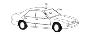
- FIG. 1 It is a perspective view which shows the state which arrange
- FIG. 1 It is a longitudinal cross-sectional view which shows the state by which the antenna apparatus of this Embodiment is arrange
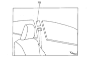
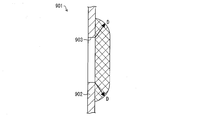
- FIG. 5 is a cross-sectional view of the main part of the vehicle body showing the arrangement range of the antenna device within a certain distance D from the window when the antenna device of the present embodiment is arranged in the vehicle. It is a block diagram which shows the schematic structure of the antenna system of this Embodiment.
- FIG. 48 is an explanatory diagram illustrating an arrangement state of the antenna device when the four antenna devices of the antenna system illustrated in FIG. 47 are arranged on the same plane to form a diversity configuration, and (a) is based on the antenna device.
- a state in which the antenna device is disposed at the first position (b) is a state in which the antenna device is rotated 90 degrees clockwise from the first position (rotated by 90 degrees around the y-axis) and is disposed in the second position, and (c) is an antenna device. Is rotated 180 degrees clockwise from the first position (rotated 180 degrees around the y axis) and placed at the third position, (d) is the antenna apparatus rotated 270 degrees clockwise from the first position (y axis) It is explanatory drawing which shows the state arrange
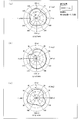
- FIG. 48 is a graph showing radiation patterns on the xy plane, the yz plane, and the zy plane in the 550 MHz band of the antenna device at the first position shown in FIG. 48A
- FIG. 48A is a graph showing the radiation pattern on the xy plane
- (B) is a graph which shows the radiation pattern of a yz surface
- (c) is a graph which shows the radiation pattern of a yz surface.
- 48 is a graph showing radiation patterns on the xy plane, yz plane, and zy plane in the 550 MHz band of the antenna device at the second position shown in FIG. 48B, and FIG.
- 48A is a graph showing the radiation pattern on the xy plane;
- (B) is a graph which shows the radiation pattern of a yz surface,
- (c) is a graph which shows the radiation pattern of a yz surface.
- 48 is a graph showing radiation patterns on the xy plane, the yz plane, and the zy plane in the 550 MHz band of the antenna device at the third position shown in FIG. 48C, and (a) is a graph showing the radiation pattern on the xy plane;
- B) is a graph which shows the radiation pattern of a yz surface,
- (c) is a graph which shows the radiation pattern of a yz surface.
- FIG. 48 is a graph showing radiation patterns on the xy plane, the yz plane, and the zy plane in the 550 MHz band of the antenna device at the fourth position shown in FIG. 48D
- FIG. 48A is a graph showing the radiation pattern on the xy plane
- (B) is a graph which shows the radiation pattern of a yz surface
- (c) is a graph which shows the radiation pattern of a yz surface.
- 49 is a graph showing radiation patterns on the xy plane, the yz plane, and the zy plane in the 550 MHz band when diversity is performed by the antenna device at the first position and the second position shown in FIGS.
- FIG. 1 is a graph showing the radiation pattern on the xy plane
- (b) is a graph showing the radiation pattern on the yz plane
- (c) is a graph showing the radiation pattern on the yz plane.
- 49 is a graph showing radiation patterns on the xy plane, the yz plane, and the zy plane in the 550 MHz band when diversity is performed by the antenna device from the first position to the third position shown in FIGS.
- (A) is a graph showing the radiation pattern on the xy plane
- (b) is a graph showing the radiation pattern on the yz plane
- (c) is a graph showing the radiation pattern on the yz plane.
- FIG. 49 is a graph showing radiation patterns on the xy plane, the yz plane, and the zy plane in the 550 MHz band when diversity is performed by the antenna device from the first position to the fourth position shown in FIGS.
- (A) is a graph showing the radiation pattern on the xy plane
- (b) is a graph showing the radiation pattern on the yz plane
- (c) is a graph showing the radiation pattern on the yz plane.
- FIG. 48 is an explanatory diagram showing an arrangement state of the antenna device when the four antenna devices of the antenna system shown in FIG.
- FIG. 47 are arranged in a state where they are rotated around the x axis to form a diversity configuration;
- the state where the antenna device is disposed at the first reference position (b) is the state where the antenna device is rotated 90 degrees around the x axis from the first position and is disposed at the second position, and (c) is the state where the antenna device is disposed at the second position.
- FIG. 48 is an explanatory diagram showing an arrangement state of the antenna device when the four antenna devices of the antenna system shown in FIG. 47 are arranged in a state of being rotated around the z axis to form a diversity configuration;
- the state where the antenna device is disposed at the first reference position (b) is the state where the antenna device is rotated 90 degrees around the z axis from the first position and is disposed at the second position, and (c) is the state where the antenna device is disposed at the second position.
- a state where the antenna device is rotated 180 degrees around the z-axis from the first position and disposed at the third position, and (d) is a state where the antenna device is rotated 270 degrees around the z-axis from the first position and disposed at the fourth position.
- FIG. 48 is a perspective view showing a state where four antenna devices are arranged on surfaces having different angles of a bumper of an automobile in the antenna system shown in FIG. 47.
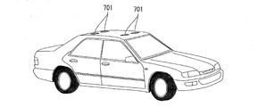
- 47 is a perspective view showing a state in which a plurality of antenna devices are arranged on the outer surface of the vehicle body of the automobile in the antenna system shown in FIG. 47, wherein (a) shows the antenna devices arranged on the roof top, bonnet and front bumper of the automobile.
- the perspective view which shows a state, (b) is a perspective view which shows the state by which the antenna apparatus is arrange
- 47 is a perspective view showing a state in which a plurality of antenna devices are arranged in a vehicle of the vehicle in the antenna system shown in FIG.
- FIG. 47 wherein (a) shows two antenna devices at the back of the roof of the vehicle (ceiling inside the vehicle).
- 47 is a perspective view showing a state in which a plurality of antenna devices are arranged at positions different from the positions shown in FIG. 60 in the vehicle in the antenna system shown in FIG. 47, wherein (a) shows the antenna device as a center pillar.
- FIG. 47 is a perspective view showing a state where four antenna devices are arranged on the roof top on the outer surface of the vehicle body.
- FIG. 48 is a perspective view showing a state in which a total of three antenna devices are arranged on the roof top and left and right front pillars on the outer surface of the vehicle body in the antenna system shown in FIG. 47.
- FIG. 47 is a perspective view showing a state where four antenna devices are arranged on the roof top on the outer surface of the vehicle body.
- FIG. 48 is a perspective view showing a state in which a total of three antenna devices are arranged on the roof top and left and right front pillars on the outer surface of the vehicle body in the antenna system shown in FIG. 47.
- 47 in the case where two to four antenna devices are dispersedly disposed on the outer surface of the vehicle body, and on any of the roof top, the left and right front pillars, and the left and right rear pillars. It is a perspective view which shows an example of an arrangement
- FIG. 47 is a perspective view showing a state in which a plurality of antenna devices are arranged on a pillar in a car of the automobile in the antenna system shown in FIG. 47, where (a) shows a state in which the antenna devices are arranged on the left and right rear pillars, respectively.
- a perspective view and (b) are perspective views which show the state which has arrange
- 47 is a perspective view showing a state in which a plurality of antenna devices are arranged on the back of the roof and the center pillar in the interior of the automobile in the antenna system shown in FIG. 47, (a) is the center in the vehicle width direction on the back of the roof.
- FIG. 7B is a perspective view showing a state in which the antenna device is arranged in the vicinity
- FIG. 5B is a perspective view showing a state in which the antenna device is arranged in the vicinity of the window and the center pillar on the back of the roof.
- FIG. 47 it is a perspective view which shows the state which has arrange
- FIG. 48 is a perspective view showing an arrangement state of the antenna device when diversity is performed by a plurality of antenna devices arranged on the outer surface of the automobile body and in the automobile in the antenna system shown in FIG. 47.
- FIG. 1 is a plan view showing a schematic configuration of the antenna device according to Embodiment 1 of the present invention.
- the antenna device 101 includes a radiating element 115.
- the radiating element 115 is formed on the surface of a base material having a flat surface, for example.
- the radiating element 115 has a conductive path continuous from one end to the other end. From the point of view of having a conductive path continuous from one end to the other, it can be said that the radiating element 115 is formed in a loop shape as in the known loop antenna device. And the radiation element 115 is arrange
- first root portion (one root portion) 117 a portion on one end side is a first root portion (one root portion) 117, and a portion on the other end side is a second root portion (the other root portion) 118. It has become.
- a part (first part) of the intermediate part between the first root part 117 and the second root part 118 of the conductive path constitutes the first radiating part 111 and the remaining part ( The second portion) constitutes the second radiating portion 112.
- the first root part 117 and the second root part 118 constitute a winding part (first area) 113.
- the radiating element 115 includes two root portions 117 and 118, and a first radiation portion 111 and a second radiation portion 112 between the root portions 117 and 118.
- the first radiating portion 111 has a meander shape (a meander line antenna shape, a meander shape portion), and the second radiating portion 112 has a linear shape.
- the size of the antenna device 101 is 70 mm in the left-right direction (Y-axis direction) in FIG. 1 and 30 mm in the vertical direction (X-axis direction) in FIG.
- the first and second root portions 117 and 118 of the radiating element 115 are formed with a power feeding portion 114.
- a power supply line 121 is connected to the power supply unit 114, and thereby the power is supplied from the power supply line 121 to the radiating element 115.
- the direction of taking out the first root part 117 of the radiating element 115 is leftward in FIG. 1 (the negative direction of the Y axis), and the second root part 118 of the radiating element 115 is taken out. Is the right direction in FIG. 1 (the positive direction of the Y axis). That is, the two directions of taking out are opposite to each other.
- the two root portions 117 and 118 of the radiating element 115 are taken out in the direction in which the first root portion 117 extends from the position of the power feeding portion 114 and the feed line 121 extends, that is, in the left direction in FIG. (The negative direction of the Y axis), and the second root portion 118 is opposite to the direction in which the power supply line 121 extends from the position of the power supply portion 114 (the left direction in FIG. 1).
- the extending direction of the first root part 117 extends from one end of the radiating element 115 to the left in FIG. 1 (negative direction of the Y axis) and upward (X Negative direction of the axis), right direction (positive direction of the Y axis), downward direction (positive direction of the X axis), left direction (negative direction of the Y axis, extraction direction), the second root part
- the extending direction of 118 is from the other end of the radiating element 115 to the right in FIG.
- antenna device 101 can realize a maximum radiation gain of 4 dBi in the 470 MHz to 860 MHz band by such a configuration of winding unit 113 surrounding power feeding unit 114.
- the first radiating portion 111 of the radiating element 115 is continuous with the first root portion 117 and has a meander shape including at least one folded pattern.
- the folding direction (X-axis direction in FIG. 1) of this meander-shaped folding pattern is perpendicular to the direction of taking out the first root portion 117 of the radiating element 115 in the winding portion 113.
- the second radiating portion 112 of the radiating element 115 has a linear shape.
- the extending direction (Y-axis direction in FIG. 1) of the linear shape (radiating portion 112) is parallel to the direction of taking out the second root portion 118 of the radiating element 115 in the winding portion 113.
- the meander-shaped folding direction of the first radiating portion 111 and the extending direction of the linear shape of the second radiating portion 112 are orthogonal to each other. ing.
- a feeding line 121 is arranged on the winding part 113, and is positioned below the feeding line 121 and overlaps with the feeding line 121.
- the line width of the first root portion 117 of the element 115 is wider than the line width at other positions that are not located below the feeder line 121.
- impedance matching can be realized in the power feeding unit 114.
- the pattern in which the line width is increased in this way is hereinafter referred to as an inductance matching pattern (wide portion) 116.
- a pattern with a wide line width is referred to as an inductance matching pattern (wide portion) 116 because the pattern with a wide line width is input to the antenna device 110. This is because it functions as an inductor having inductive reactance and changes the input impedance of the antenna device 101.
- the contribution to the input impedance of a pattern with a wide line width is not limited to the inductance. That is, a pattern with a wide line width may function as a capacitor having a capacitive reactance, and the input impedance of the antenna device 101 may be changed.
- the antenna device 101 can reduce the VSWR of the radiating element 115 by such an arrangement configuration of the inductance matching pattern 116. For this reason, the usable bandwidth in which the value of VSWR is equal to or less than the specified value can be expanded. Therefore, it is possible to realize a usable band including the band of the radio wave, regardless of whether the radio wave on the low frequency band side or the radio wave on the high frequency band side is transmitted / received.
- the configuration related to the inductance matching pattern 116 will be described later in detail with reference to FIG.
- the winding unit 113 includes the first root part 117 and the second root part 118 of the radiating element 115.
- One root portion 117 of the radiating element 115 includes a first straight portion extending leftward in FIG. 2 (a negative direction of the Y axis) from one end of the radiating element 115 and upward (in the X axis direction of FIG. 2).
- the second bent portion is connected to the first straight portion via a first bent portion extending in the negative direction and extends rightward in FIG. 2 (positive direction of the Y axis) from the first bent portion.
- the straight portion is connected to the second straight portion via a second bent portion that extends downward in FIG. 2 (the positive direction of the X axis), and from the second bent portion to the left in FIG. 2 (Y axis) And a third straight portion extending in the negative direction).
- the first root portion 117 of the radiating element 115 includes a first straight portion 117o1 extending leftward from one end of the radiating element 115 (a negative direction of the Y axis), and the first straight line.
- a first bent portion 117o2 extending upward from the end portion of the portion 117o1 (negative direction of the X axis), and extending rightward from the end portion of the first bent portion 117o2 (positive direction of the Y axis).
- the second straight portion 117o3, the second bent portion 117o4 extending downward (the positive direction of the X axis) from the end portion of the second straight portion 117o3, and the end of the second bent portion 117o4 And a third straight portion (rear end straight portion) 117o5 extending leftward from the portion (the negative direction of the Y axis).
- the first root portion 117 of the radiating element 115 is arranged such that the first to third straight portions 117o1, 117o3, 117o5 sequentially connected via the first and second bent portions 117o2, 117o4 are parallel to each other. It is formed in a rectangular spiral shape.
- the other root portion 118 of the radiating element 115 includes a fourth straight portion extending from the other end of the radiating element 115 rightward in FIG. 2 (positive direction of the Y axis), and downward (X Connected to the fourth straight part via a third bent part extending in the positive direction of the axis) and extending leftward in FIG. 2 (negative direction of the Y axis) from the third bent part. 5 and a fourth bent portion that extends upward (in the negative direction of the X axis) in FIG. 2 and is connected to the fifth straight portion through the fourth bent portion to the right in FIG. And a sixth straight portion extending in the positive direction of the Y-axis.
- the second root portion 118 of the radiating element 115 includes a fourth straight portion 118o1 extending rightward from the other end of the radiating element 115 (positive direction of the Y axis), and the fourth straight line.
- a third bent portion 118o2 extending downward from the end portion of the portion 118o1 (positive direction of the X axis), and extending leftward from the end portion of the third bent portion 118o2 (negative direction of the Y axis)
- a fifth straight portion 118o3, a fourth bent portion 118o4 extending upward (negative direction of the X axis) from the end of the fifth straight portion 118o3, and an end of the fourth bent portion 118o4
- a sixth straight part (rear end straight part) 118o5 extending rightward (positive direction of the Y-axis) from the part.
- the second root portion 118 of the radiating element 115 is also arranged so that the fourth to sixth straight portions 118o1, 118o3, 118o5 sequentially connected via the third and fourth bent portions 118o2, 118o4 are parallel to each other. It is formed in a rectangular spiral shape.
- the end of the first straight portion 117o1 in the first root portion 117 is in the width direction of the first straight portion 117o1 and in the direction of the fourth straight portion 118o1 of the second root portion 118.
- a protruding convex portion 117o11 is formed.
- Convex part 118o11 which protrudes in is formed.
- the convex portion 117o11 and the convex portion 118o11 are arranged so as to be adjacent to each other in the Y direction shown in FIG. 2 and to face in opposite directions in the X direction. Further, the first root portion 117 and the second root portion 118 are arranged in a rectangular spiral shape with the convex portions 117o11 and 118o11 as starting ends, that is, with the center of the spiral.
- the power supply to the first root portion 117 of the radiating element 115 is performed from the power supply portion 114 formed at the end thereof.
- the power supply to the second root portion 118 of the radiating element 115 is performed not from the end portion but from the power supply portion 114 formed in the middle of the third bent portion 118o2 of the root portion 118.
- the power feeding unit 114 includes a convex portion 117o11 of the first straight portion 117o1 in the first root portion 117, and a third bend in the second root portion 118 adjacent to the convex portion 117o11 in the Y direction. It arrange
- the power feeding line 121 is arranged in the left-right direction in FIG. 2, and the power feeding line 121 and the power feeding unit 114, that is, the power feeding line 121 and the first and second root parts 117 and 118 are connected.
- the configuration is realized.
- the outer conductor 122 of the coaxial cable constituting the power supply line 121 is connected to the first root portion 117 (the convex portion of the first straight portion 117 o 1) of the radiating element 115. 117o11), and the inner conductor 123 of the coaxial cable supplies power to the second root portion 118 of the radiating element 115 (intermediate portion of the third bent portion 118o2).
- the portion of the coaxial cable as the feeder 121 that is covered with the insulating outer shell and adjacent to the portion where the outer conductor 122 is exposed is the fourth straight portion. It is arrange
- a signal in a predetermined frequency band is transmitted through the inner conductor 123 of the coaxial cable constituting the power supply line 121 to the second root portion 118 of the radiating element 115.
- the ground potential is applied to the first root portion 117 of the radiating element 115 via the outer conductor 122 of the coaxial cable.
- the fourth straight portion 118o1 of the second root portion 118 of the radiating element 115 is formed with a convex portion 118o11 protruding in the width direction (vertical direction in FIG. 2, X direction) at the end portion.
- the above-described inductance matching pattern 116 is provided in the straight portion 118o1 by the convex portion 118o11.
- the inductance matching pattern 116 functions as an inductor in impedance matching between the power supply line 121 and the power supply unit 114. That is, a convex portion 118o11 is formed on the straight portion 118o1 of the second root portion 118, and the power supply line 121 is disposed on the convex portion 118o11.
- the part of the 4th straight part 118o1 in which the convex part 118o11 in which it is located under the feeder line 121 and overlaps with the feeder line 121 is formed is a line rather than the other part which is not located under the feeder line 121.
- the wide part is wide.
- the line width of the wide part may be wider than the minimum line width of the intermediate part of the radiating element 115. That is, “the other part that is not located below the feeder line 121” refers to a part of the intermediate part of the radiating element 115 that has the smallest line width.
- the line width of the wide portion is preferably 1.2 times or more and 4.5 times or less the diameter of the feeder line 121.
- the two root portions 117 and 118 of the radiating element 115 are drawn out in directions opposite to each other while surrounding the power feeding portion 114, and the first radiating portion 111 and the second radiating portion 112 shown in FIG. Are connected to each other.
- the two root portions 117 and 118 of the radiating element 115 can be accommodated in a relatively narrow rectangular area. Therefore, the above arrangement contributes to forming the peripheral portion of the power feeding unit 114 in a compact manner.
- FIG. 3 shows an antenna device 101 a that is a modification of the antenna device 101.
- a part of the intermediate portion thereof constitutes the first radiating portion 111a, and the other portion of the intermediate portion thereof constitutes the second radiating portion 112a, while the two root portions 117a and 118a thereof. Constitutes a winding part (first region) 113a.
- a part of the intermediate portion of the radiating element 115a has a meander shape including at least one folded pattern in the first radiating portion 111a.
- the folding direction of the meander-shaped folding pattern is perpendicular to the direction of taking out the first root portion 117a of the radiating element 115a in the winding portion 113a.
- the other part of the intermediate portion of the radiating element 115a also has a meander shape in the second radiating portion 112a.
- the extending direction of the meander shape is parallel to the direction of taking out the second root portion 118a of the radiating element 115a in the winding portion 113a.
- One root portion of the radiating element 115a includes a first straight portion extending leftward in FIG. 3 (negative Y-axis direction) from one end of the radiating element 115a and upward (negative X-axis) in FIG.
- the second straight line is connected to the first straight part through the first bent part extending in the direction of (b) and extends rightward (positive direction of the Y axis) in FIG. 3 from the first bent part. 3 and a second bent portion that extends downward in FIG. 3 (positive direction of the X axis) and is connected to the second straight portion from the second bent portion in FIG.
- a third straight portion extending in the negative direction.
- the first root portion 117a of the radiating element 115a includes a first straight line portion 117a1 extending leftward from one end of the radiating element 115a in FIG. 3 (the negative direction of the Y axis), and the first straight line portion 117a1.
- a first bent portion extending upward (a negative direction of the X axis) from the end of the portion 117a1, and a first bent portion extending rightward (a positive direction of the Y axis) from the end of the first bent portion.
- the other root portion of the radiating element 115a has a fourth linear portion extending rightward in FIG. 3 (positive direction of the Y axis) from the other end of the radiating element 115a, and downward (X axis) in FIG. Is connected to the fourth straight portion via a third bent portion extending in the positive direction), and extends from the third bent portion to the left in FIG. 3 (the negative direction of the Y axis). 3 and a fourth bent portion extending upward (in the negative direction of the X axis) in FIG. 3, and connected to the fifth straight portion from the fourth bent portion to the right (Y And a sixth straight portion extending in the positive direction of the shaft.
- the second root portion 118a of the radiating element 115a includes a fourth straight portion 118a1 extending rightward (positive direction of the Y axis) from the other end of the radiating element 115a, and the fourth straight line.
- a third bent portion extending downward from the end of the portion 118a1 (positive direction of the X axis), and a third bent portion extending leftward from the end of the third bent portion (negative direction of the Y axis).
- the power supply to the first root portion 117a of the radiating element 115a is performed from a power supply portion 114a formed in the middle of the first straight portion 117a1.
- the power supply to the second root portion 118a of the radiating element 115a is also performed from the power supply portion 114a formed in the middle of the fourth straight portion 118a1.
- the first root part 117a of the radiating element 115a has a convex part 117a11 projecting in the width direction (vertical direction in FIG. 3, X-axis direction, fourth linear part 118a1 direction). It has in the middle of the 1st straight part 117a1.
- the second root portion 118a of the radiating element 115a also has a convex portion 118a11 projecting in the width direction (vertical direction, X-axis direction, first linear portion 117a1 direction in FIG. 3) of the fourth linear portion 118a1. It has in the middle.
- each convex part 117a11, 118a11 of the two root parts 117a, 118a is arrange
- a configuration in which the power supply line 121a is arranged in the left-right direction (Y-axis direction) in FIG. 3 and the power supply line 121a and the power supply unit 114a are connected is realized.
- the line width of the portion where the portion covered with the insulating sheath of the power supply line 121a is disposed is the wide portion.
- the inductance matching pattern 116a is configured.
- FIG. 4 shows an antenna device 101 b which is a modification of the antenna device 101.
- the radiating element 115b is configured such that a part of the intermediate part thereof constitutes the first radiating part 111b and the other part of the intermediate part thereof constitutes the second radiating part 112b, while the two root parts 117b, 118b constitutes a winding part (first region) 113b. Further, the first radiating portion 111b has a meander shape, and the second radiating portion 112b also has a meander shape.
- One root portion of the radiating element 115b includes a first straight portion extending leftward in FIG. 4 (negative Y-axis direction) from one end of the radiating element 115b, and upward (negative X-axis) in FIG.
- the second straight line is connected to the first straight part via the first bent part extending in the direction of (b) and extends rightward in FIG. 4 (positive direction of the Y axis) from the first bent part. 4 and a second bent portion that extends downward in FIG. 4 (the positive direction of the X axis), and is connected to the second straight portion from the second bent portion in FIG.
- a third straight portion extending in the negative direction.
- the first root portion 117b of the radiating element 115b includes a first straight portion 117b1 extending leftward in FIG. 4 from the one end of the radiating element 115b (the negative direction of the Y axis) in FIG. A first bend extending from the end of one straight portion 117b1 (the negative direction of the X axis), and extending from the end of the first bend to the right (the positive direction of the Y axis).
- a second straight portion that exists a second bent portion that extends downward from the end of the second straight portion (positive direction of the X axis), and a leftward direction from the end of the second bent portion
- a third straight portion extending in the negative direction of the Y-axis.
- the other root portion of the radiating element 115b has a fourth linear portion extending rightward in FIG. 4 (positive direction of the Y axis) from the other end of the radiating element 115b, and downward (X axis) in FIG. Is connected to the fourth straight line portion via a third bent portion 119b extending in the positive direction), and extends from the third bent portion to the left in FIG. 4 (the negative direction of the Y axis). 5 and a fourth bent portion that extends upward (in the negative direction of the X-axis) in FIG. 4 and is connected to the fifth straight portion through the fourth bent portion to the right in FIG. And a sixth straight portion extending in the positive direction of the Y-axis.
- the second root portion 118b of the radiating element 115b includes a fourth straight portion 118b1 extending rightward (positive direction of the Y axis) from the other end of the radiating element 115b, and the fourth straight line.
- a third bent portion 119b extending downward from the end portion of the portion 118b1 (positive direction of the X axis), and extending leftward from the end portion of the third bent portion 119b (negative direction of the Y axis).
- the second root portion 118b of the radiating element 115b further includes a seventh straight portion 120b extending in the vertical direction (X-axis direction) in FIG.
- the seventh straight portion 120b is connected to the vicinity of the center of each of the fourth straight portion 118b1 and the fifth straight portion 118b3.
- the fourth straight portion 118b1 and the fifth straight portion 118b3 are replaced by the third bent portion 119b and the seventh straight portion. It is connected via both 120b.
- the antenna device 101b that achieves a wide band is realized by increasing the current path in the second root portion 118b of the radiating element 115b and increasing the resonance point.
- the power supply to the first root portion 117b of the radiating element 115b is performed from the power supply portion 114b formed at the end thereof.
- the power supply to the second root portion 118b of the radiating element 115b is performed not from the end portion but from the power supply portion 114b formed in the middle of the first straight line portion.
- the first root portion 117b of the radiating element 115b has a convex portion 117b11 projecting in the width direction (vertical direction in FIG. 4, the fourth straight portion 118b1 direction) as the first straight line.
- the second root portion 118b of the radiating element 115b has a convex portion 118b11 projecting in the width direction (vertical direction in FIG. 4, the first straight portion 117b1 direction) in the middle of the fourth straight portion 118b1. is doing.
- the convex portions 117b11 and 118b11 of the two root portions 117b and 118b are arranged so as to be adjacent to each other in the left-right direction in FIG. 4 (the extending direction of the feeder line 121b). By doing so, a configuration in which the power supply line 121b is arranged in the left-right direction in FIG. 4 and the power supply line 121b and the power supply unit 114b are connected is realized.
- the line width of the portion where the portion covered with the insulating sheath of the power supply line 121b is arranged is the wide portion.
- an inductance matching pattern 116b is configured.
- FIG. 5 shows an antenna device 101 c that is a modification of the antenna device 101.
- the first radiating portion 111c has a meander shape, and the second radiating portion 112c has a linear shape.
- the second radiating portion 112c is composed of two linear paths that are adjacent to each other, and the two linear paths are one end of each other and the other end of each other. They are connected to each other. That is, they are connected in parallel.
- the first radiating portion 111c has two straight paths 111c1 connected to the two straight paths constituting the second radiating section 112c.
- the two linear paths 111c1 included in the first radiating portion 111c are also connected to each other one end and each other end. That is, they are connected in parallel.
- the direction of taking out the first root portion 117c of the radiating element 115c is downward (the positive direction of the X axis) in FIG.
- the root 118c is taken out in the upward direction in FIG. 5 (the negative direction of the X axis). That is, the directions of taking out these two root portions 117c and 118c are opposite to each other.
- the two root portions 117c and 118c of the radiating element 115c are taken out from the first root portion 117c in the direction in which the feeder 121c extends, that is, in the downward direction in FIG. 5 (the positive direction of the X axis). ), And the second root portion 118c is opposite to the direction in which the feeder line 121c extends (downward in FIG. 5, positive direction of the X axis).
- the extending direction of the first root part 117c is upward (negative X-axis direction), rightward (Y-axis positive direction), downward (in FIG. X-axis positive direction, take-out direction), and the extending direction of the second root part 118 is downward (positive X-axis direction), leftward (negative Y-axis direction), upward (The negative direction of the X axis, the direction of taking out).
- the antenna device 101 can realize a minimum radiation gain of 1 dBi in the 470 MHz to 860 MHz band.
- the first root portion 117c of the radiating element 115c includes a first straight portion 117c1 extending upward from one end of the radiating element 115c (in the negative direction of the X axis) in FIG.
- a first bent portion 117c2 extending rightward from the end portion of the straight portion 117c1 (positive direction of the Y axis) and downward from the end portion of the first bent portion 117c2 (positive direction of the X axis)
- a second straight portion (rear end straight portion) 117c3 that extends.
- the first root portion 117c of the radiating element 115c is U-shaped so that the first straight portion 117c1 and the second straight portion 117c3 that are adjacent to each other via the first bent portion 117c2 are parallel to each other. It is formed so as to be bent.
- the second root portion 118c of the radiating element 115c and the third straight portion 118c1 extending downward from the other end of the radiating element 115c (positive direction of the X axis)
- a second bent portion 118c2 extending leftward from the end of the straight portion 118c1 (negative direction of the Y axis) and upward from the end of the second bent portion 118c2 (negative direction of the X axis)
- a fourth straight portion (rear end straight portion) 118c3 extending.
- the second root portion 118c of the radiating element 115c is also U-shaped so that the third straight portion 118c1 and the fourth straight portion 118c3 that are adjacent to each other through the second bent portion 118c2 are parallel to each other. It is formed so as to be bent.
- the power supply to the first root portion 117c of the radiating element 115c is performed from a power supply portion 114c formed in the middle of the first straight portion 117c1.
- the power supply to the second root portion 118c of the radiating element 115c is also performed from the power supply portion 114c formed in the middle of the third linear portion 118c1.
- the first root portion 117c of the radiating element 115c has a convex portion 117c11 that protrudes in the width direction (the left-right direction in FIG. 5, the Y-axis direction, and the third linear portion 118c1 direction). It has in the middle of the 1st straight part 117c1.
- the second root portion 118c of the radiating element 115c also has a convex portion 118c11 projecting in the width direction (the left-right direction in FIG. 5, the Y-axis direction, the first straight portion 117c1 direction) as its third straight portion 118c1. It has in the middle.
- each convex part 117c11, 118c11 of two root parts 117c, 118c is arrange
- a configuration in which the feeder line 121c is arranged in the vertical direction (X-axis direction) in FIG. 5 and the feeder line 121c and the feeder unit 114c are connected is realized.
- the line width of the portion where the portion covered with the insulating sheath of the power supply line 121 c is disposed is the wide portion.
- an inductance matching pattern 116c is configured.
- FIG. 6 shows an antenna device 101 d which is a modification of the antenna device 101.
- the radiating element 115d a part of the intermediate part thereof constitutes the first radiating part 111d, and the other part of the intermediate part thereof constitutes the second radiating part 112d, while the two root parts 117d and 118d are formed. Constitutes a winding part (first region) 113d.
- the first radiating portion 111d has a meander shape, and the second radiating portion 112d also has a meander shape.
- One root portion of the radiating element 115d includes a first straight portion extending upward (in the negative direction of the X axis) in FIG. 6 from one end of the radiating element 115d, and rightward (in the positive direction of the Y axis in FIG. 6).
- the second straight line is connected to the first straight part through the first bent part extending in the direction of (b) and extends downward (positive direction of the X axis) in FIG. 6 from the first bent part. Part.
- the first root portion 117d of the radiating element 115d in FIG. 6 includes a first straight portion 117d1 extending upward from one end of the radiating element 115d (in the negative direction of the X axis) and the first straight line.
- a first bent portion 117d2 extending rightward from the end portion of the portion 117d1 (positive direction of the Y axis), and extending downward from the end portion of the first bent portion 117d2 (positive direction of the X axis)
- the other root portion of the radiating element 115d has a third straight line portion extending downward (in the positive X-axis direction) in FIG. 6 from the other end of the radiating element 115d, and leftward (Y-axis in FIG. 6).
- a fourth bent portion extending upward (in the negative direction of the X axis) in FIG. 6 from the second bent portion, and connected to the third straight portion via a second bent portion extending in the negative direction). And a straight portion.
- the second root portion 118d of the radiating element 115d has a third straight portion 118d1 extending downward (positive direction of the X axis) from the other end of the radiating element 115d, and the third straight line.
- a second bent portion 118d2 extending leftward from the end of the portion 118d1 (negative direction of the Y-axis), and extending upward (negative direction of the X-axis) from the end of the second bent portion 118d2
- the power supply to the first root portion 117d of the radiating element 115d is performed from a power supply portion 114d formed at the end thereof.
- the power supply to the second root portion 118d of the radiating element 115d is also performed from the power supply portion 114d formed at the end thereof.
- the first root portion 117d of the radiating element 115d has a convex portion 117d11 that protrudes in the width direction (the left-right direction in FIG. 6, the Y-axis direction, and the third linear portion 118d1 direction).
- the first straight portion 117d1 is provided.
- the second root portion 118d of the radiating element 115d also has a convex portion 118d11 projecting in the width direction (the left-right direction in FIG. 6, the Y-axis direction, the first straight portion 117d1 direction) as its third straight portion 118d1.
- each convex part 117d11 and 118d11 of two root parts 117d and 118d are arrange
- a configuration is realized in which the feeder line 121d is arranged in the vertical direction (X-axis direction) in FIG. 6 and the feeder line 121d and the feeder portion 114d are connected.
- the inductance matching pattern 116d is configured by making the second bent portion 118d2 of the second root portion 118d of the radiating element 115d a wide portion.
- the second root portion 118 of the radiating element 115d can be made shorter than in the case of FIG. 5, and can be accommodated in a relatively narrow region. Therefore, the above arrangement contributes to the compact formation of the winding part 113d.
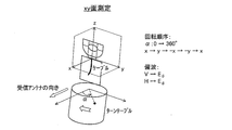
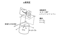
- the xy plane, the yz plane, and the zx plane are set as shown.
- the direction of the receiving antenna for measurement is sequentially in the xy plane so as to be the positive x-axis direction, the positive y-axis direction, the negative x-axis direction, the positive y-axis direction, and the positive x-axis direction.
- the rotation angle ⁇ of the turntable may be changed from 0 ° to 360 °.
- the antenna device 101a is disposed at a position indicated by the direction of the receiving antenna shown in FIG. 8, and is separated by a predetermined distance (for example, 3 m).
- the radiation characteristics of the yz plane and the zx plane are calculated in the same manner as described above.
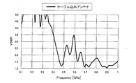
- FIG. 11 is a graph showing the VSWR characteristics of the antenna device 101a shown in FIG.
- FIG. 12 is a graph showing radiation patterns in the 470 MHz band and the 500 MHz band of the antenna device 101a shown in FIG.
- FIG. 12 shows a radiation pattern on the xy plane.
- FIG. 11 shows that VSWR can be suppressed to 3.5 or less in a band of 500 MHz or less in the terrestrial digital television band (470 MHz to 900 MHz).
- the meander shape (meander shape portion) of the first radiating portions 111 to 111d and the second radiating portions 112 to 112d are provided.
- the short-circuit member is not limited to being provided as an independent member, and for example, the conductive path forming the radiating element may be formed of the same material together with the conductive path.
- FIG. 13 to 15 are diagrams for explaining the second embodiment of the present invention.
- FIG. 13 is an example in which the inductance matching pattern is removed from the antenna device according to Embodiment 2 of the present invention
- FIG. 14 is an example in which the short-circuit member is removed from the antenna device according to Embodiment 2 of the present invention.
- FIG. 15 is a plan view showing a schematic configuration of the antenna apparatus according to Embodiment 2 of the present invention.
- symbol 116g in FIG. 15 show an inductance matching pattern.
- the radiation element 115g has a part of the middle part constituting the first radiation part 111g, and the other part of the middle part.
- a part constitutes the second radiating portion 112g, while the two root portions 117g and 118g constitute a winding portion (first region) 113g.
- a part of the intermediate portion of the radiating element 115g has a meander shape including at least one folding pattern in the first radiating portion 111g.
- the folding direction of the meander-shaped folding pattern is parallel to the direction of taking out the first root portion 117g of the radiating element 115g in the winding portion 113g.
- the other part of the intermediate portion of the radiating element 115g also has a meander shape in the second radiating portion 112g.
- the folding direction of the meander-shaped folding pattern is perpendicular to the direction of taking out the second root portion 118g of the radiating element 115g in the winding portion 113g.
- Short-circuit members 131g, 132g, 133g, and 134g are arranged in the meander shape of the first radiating portion 111g.
- the short-circuit member 131g is disposed in the meander shape of the second radiating portion 112g.
- the radiation element 115g can improve the radiation omnidirectionality of each radio wave in both cases of transmitting and receiving radio waves on the VHF band side and transmitting and receiving radio waves on the UHF band side. .
- the short-circuit members 131g to 134g are arranged in either meander shape of the first radiating portion 111g and the second radiating portion 112g, but of course the first radiating portion 111g. It may be disposed only within the meander shape of the second radiating portion 112g, or may be disposed only within the meander shape of the second radiating portion 112g.
- the positions and locations of the short-circuit members 131g to 134g may be determined so that the resonance point of the radiating element 115g is increased and the VSWR characteristics of the two root portions of the radiating element 115g in the power feeding unit 114g are stabilized. .
- the short-circuit members 131g to 134g are for short-circuiting the radiating element 115g, and for example, a conductive material such as a metal material can be used. Such short-circuit members 131g to 134g are in direct contact with the radiating element 115g to short-circuit the radiating element 115g.
- FIG. 16 is a graph showing the VSWR characteristics of the antenna device 101g shown in FIG.
- FIG. 17 is a graph showing a radiation pattern on the xy plane in the 550 MHz band of the antenna device 101g shown in FIG.
- FIG. 16 shows that VSWR can be suppressed to 3.5 or less in a band of 500 MHz or less in the terrestrial digital television band (470 MHz to 900 MHz).
- (With or without inductance matching pattern) 18 is a graph showing a radiation pattern on the xy plane in the 750 MHz band of the antenna device 101e shown in FIG. 13 and a radiation pattern on the xy plane in the 800 MHz band of the antenna device 101g shown in FIG.
- Presence / absence of short-circuit member and arrangement configuration of meander shape folding direction 19 shows the radiation pattern on the xy plane in the 700 MHz band of the antenna device 101f shown in FIG. 14, the radiation pattern on the xy plane in the 700 MHz band of the antenna device 101g shown in FIG. 15, and the antenna device 101h shown in FIG. It is a graph which shows the radiation pattern of the xy plane in 700 MHz band.
- a part of the intermediate portion of the radiating element 115h is the first radiating portion 111h, and the folding direction of the meander-shaped folding pattern is the first radiating element 115 in the winding portion 113h. It is parallel to the direction of taking out the root portion 117.
- the other part of the intermediate portion of the radiating element 115h is that the second radiating portion 112h has a folding direction of the meander-shaped folding pattern of the second root portion 118 of the radiating element 115 in the winding portion 113h. Parallel to the direction of removal.
- the meander-shaped folding direction of the first radiating portion 111h and the meander-shaped folding direction of the second radiating portion 112h are arranged and configured in parallel.
- the meander-shaped folding direction of the first radiating portion 111f and the second radiation is stabilized by being arranged and configured to be orthogonal to the meandering folding direction of the portion 112f.
- the antenna device when the antenna device is mounted on a conductor member made of a metal plate or the like, the influence from the conductor member is inevitable.
- the antenna device when the antenna device is mounted on the conductor member, the antenna device needs to be designed while considering the influence from the conductor member, unlike the case where the antenna device alone is in a vacuum free space.
- the short circuit member (short circuit part) is used, and the position and location which arrange
- the short-circuit member is not limited to being provided as an independent member.
- the conductive path forming the radiating element is formed of the same material together with the conductive path, and is integrated with the conductive path. It may be formed automatically.
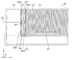
- FIG. 21 is a plan view showing a schematic configuration of the antenna device according to Embodiment 3 of the present invention. As shown in FIG. 21, the antenna device 201 includes a radiating element 215.
- the radiating element 215 has a conductive path continuous from one end to the other end, and is a single line. From the point of having a conductive path continuous from one end to the other, it can be said that it is formed in a loop shape. And the radiating element 215 is arrange
- the radiating element 215 includes a portion having a predetermined length from one end of the radiating element 215 (a portion corresponding to the winding portion 211 below) and a portion having a predetermined length from the other end (corresponding to the winding portion 211 below). Part) become the first and second root parts 225 and 226, respectively. The remaining part of the radiating element 215 excluding the two root parts 225 and 226 is an intermediate part.
- a part of the intermediate part constitutes a radiating part 212 having a meander shape (a meander-shaped part), and the remaining part of the intermediate part constitutes a first wide part 213 and a second wide part 214,
- the two root parts 225 and 226 constitute a winding part 211.
- the first wide portion 213 and the second wide portion 214 share a part of each other.
- the size of the antenna device 201 is 92 mm in the left-right direction (X-axis direction) in FIG. 21 and 52 mm in the vertical direction (Z-axis direction).
- a power feeding part 222 is formed on each of the two root parts 225 and 226 of the radiating element 215.
- Each of the two root portions 225 and 226 is supplied with power from a power supply line 221 connected to the power supply portion 222.
- the extraction direction of the first root portion 225 of the radiating element 215 is leftward in FIG. 21 (X axis negative direction), and the extraction direction of the second root portion 226 is rightward in FIG. 21 (X axis). Positive direction). That is, the two directions of taking out are opposite to each other.
- the two root portions 225 and 226 of the radiating element 215 are taken out from the first root portion 225 in the direction in which the feeder 221 extends, that is, in the left direction in FIG. 21 (negative direction of the X axis).
- the second root portion 226 is in the opposite direction to the direction in which the feeder line 221 extends.
- the extending direction of the first root part 225 is upward (positive direction of the Z axis) and leftward (from the one end of the radiating element 215).
- the extending direction of the other root part is downward (negative Z-axis direction) and rightward (positive X-axis direction, extraction direction) from the other end of the radiating element 215. That is, the second root portion 226 includes a second straight portion 226o1 extending downward and a second bent portion 226o2 (rear end straight portion) extending rightward from an end portion of the second straight portion 226o1.
- each of the two root parts 225 and 226 is rotated by 90 ° so as to surround the power feeding part 114.
- a part of the intermediate portion of the radiating element 215 has a meander shape including at least one folding pattern in the radiating portion 212.
- the folding direction (Z-axis direction) of the meander-shaped folding pattern is the direction of taking out the second root part 226 of the radiating element 215 in the winding part 211 (positive direction of the X axis), that is, the second direction. It is perpendicular to the direction of the bent portion 226o2 (rear end straight portion).
- the line width (the length in the X-axis direction) of the first wide portion 213 that is positioned below the power supply line 221 and overlaps the power supply line 221 is the same as that of the winding portion 211 and the radiation portion 212 of the radiating element 215. It is wider than the line width of the constituent parts. For this reason, impedance matching between the power supply unit 222 and the power supply line 221 can be realized.
- the second wide portion 214 is also wider than the line width of the portion constituting the winding portion 211 and the radiating portion 212 of the radiating element 215.
- the second wide portion 214 serves as the first wide portion 213. . That is, in this case, the line width (the length in the X-axis direction) of the second wide portion 214 that is positioned below the feeder line 221 and overlaps with the feeder line 221 is equal to the winding portion 211 of the radiating element 215 and the radiation. It can be said that the line width of the portion constituting the portion 212 is wider.
- a short-circuit member 231 is disposed in the meander shape of the radiating portion 212.
- the role of the short-circuit member 231 will be described below with reference to FIG.
- FIG. 22 is a schematic diagram showing a state in which the short-circuit member 331 is arranged in the radiating element 315 having a meander shape and a plurality of conductive paths are generated in the radiating element 315.
- the antenna device 301 has a radiating element 315 that is one line, and the radiating element 315 has a meander shape. That is, the radiating element 315 is meandered.
- a feed line is connected to the radiating element 315 at the feed unit 322.
- the short-circuit member 331 short-circuits, for example, two different points of the radiated element 315 that has been meandered.
- two straight portions extending in the vertical direction located at both ends of the short-circuit member 331 are short-circuited.
- the radiation element 315 includes a first path (first conductive path) indicated by a solid line corresponding to the first wavelength ⁇ 1 and a second path indicated by a broken line corresponding to the second wavelength ⁇ 2.
- a path (second conductive path) is formed.
- the meandering radiating element 315 is provided with the short-circuit member 331 so as to short-circuit a plurality of different points, thereby increasing the number of conductive paths having different lengths.
- the resonant frequency of the device 301 can be increased. Thereby, the VSWR characteristic of the antenna apparatus 301 in a use band can be improved.
- the antenna device when mounted on a conductor member, it is affected by the conductor member, so that the use band (for example, 470 MHz to 770 MHz for a terrestrial digital broadcast antenna for Japan, The VSWR characteristics at 470 MHz to 860 MH for a digital broadcasting antenna and 470 to 890 MHz for a terrestrial digital broadcasting antenna for Europe) may deteriorate (VSWR value increases).
- the use band for example, 470 MHz to 770 MHz for a terrestrial digital broadcast antenna for Japan
- the VSWR in the use band is provided by providing the shorting member 331 so as to short-circuit a plurality of different points in the meandering radiation element 315. It is possible to suppress deterioration of characteristics (increase in VSWR value). That is, in consideration of the influence from the conductor member, the position where the short-circuit member 331 short-circuits in the radiating element 315 is determined in the state where the dummy conductive member is disposed in the vicinity of the radiating element 315, and the short-circuit member 331 is disposed. As a result, the number of conductive paths having different lengths increases, and the resonance frequency of the antenna device 301 increases. As a result, even when the antenna device 301 is mounted on a conductor member, it is possible to suppress deterioration of the VSWR characteristics (increase in the VSWR value) in the use band due to the influence of the conductor member.
- the short-circuit member 231 is arranged in the meandering radiation section 212 as the short-circuit member 331 as described above. Determination of the position and location which arrange
- the arrangement of the short-circuit member 231 is smaller than that in the case where the short-circuit member 231 is not arranged in a state where the radiating element 215 is arranged on the metal plate via the dielectric, and at each frequency in the use band. Decide as follows. More preferably, the VSWR value at each frequency in the use band is determined to be 3.5 or less in a state where the radiating element 215 is disposed on the metal plate via the dielectric.
- the short-circuit member 231 is moved while monitoring the VSWR value in the use band. . And when the position where VSWR value becomes smaller than the case where the short circuit member is not arrange
- the short-circuit member 231 is for short-circuiting predetermined positions of the radiating element 215, and for example, a conductive material such as a metal material can be used.
- a conductive material such as a metal material can be used.
- the short-circuit member 231 directly contacts the radiating element 215 and short-circuits the radiating element 215.
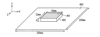
- an antenna device 401 was mounted on a metal plate 403 as a conductor member of 350 mm ⁇ 250 mm through a dielectric layer 402.
- the dielectric layer 402 will be described later. If the size of the antenna device 401 is about 100 mm ⁇ 50 mm, the antenna device 401 is mounted on a conductor member such as a hood of an automobile. It can also be obtained when installed.
- the antenna device 401 As the antenna device 401, the antenna device 201 shown in FIG. 21 and the antenna device 501 shown in FIG. 24 were used, and the VSWR characteristics were measured for each. Note that the antenna device 501 in FIG. 24 has the same configuration as the antenna device 201 in FIG. 21 except that the short-circuit member 231 provided in the antenna device 201 in FIG. 21 is not provided.
- FIG. 25 is a graph showing measurement results of the VSWR characteristics of the antenna device 201 and the antenna device 501.
- the graph “with short circuit member” is the measurement result of the antenna device 201
- the graph of “without short circuit member” is the measurement result of the antenna device 501.
- the thickness d of the dielectric layer 402 was 5 mm
- the relative dielectric constant ⁇ r was 1.
- the short circuit member 231 is arranged in the antenna device 201 to cause a short circuit, so that the VSWR is 3.5 in the band of 800 MHz or less in the terrestrial digital television band (470 MHz to 770 MHz). It can be seen that
- the inventors provide a dielectric layer 402 between the antenna device 401 and a metal plate 403 as a conductor member, thereby providing a gap between the antenna device 401 and the conductor member (metal plate 403). It has been found that an antenna device having VSWR characteristics that can withstand practical use can be realized even if the distance is reduced to about several millimeters. At this time, it is desirable to set the relative dielectric constant ⁇ r of the dielectric layer 402 to 1 or more and 10 or less. This is because if the relative dielectric constant ⁇ r is greater than 10, the reduction in radiation efficiency cannot be ignored.
- FIG. 26 shows the measurement results of the VSWR characteristics of the antenna device 401 at each thickness d when the thickness d of the dielectric layer 402 is changed.
- the antenna device 201 in FIG. 21 is used as the antenna device 401.
- d infinity is a condition that means that the distance between the antenna device 201 and the metal plate 403 is infinite, that is, the state where the metal plate 403 does not exist.
- d 0 mm is a condition that means a situation where the antenna device 201 is mounted so as to be in direct contact with the metal plate 403.
- the thickness d of the dielectric layer 402 between the antenna device 201 and the metal plate 403, that is, the distance between the antenna device 201 and the metal plate 403 should be 5 mm or more.
- VSWR can be suppressed to 3.5 or less in the band of 470 MHz to 770 MHz.
- the distance between the antenna device 201 and the metal plate 403 is 2 mm or more, the VSWR can be suppressed to 3.5 or less in a band of 470 MHz to 770 MHz except for some exceptional bands. It can be said.
- FIG. 27 is a graph showing a radiation pattern in the 550 MHz band of the antenna device 201 shown in FIG. (A) is a radiation pattern on the xy plane, (b) is a radiation pattern on the yz plane, and (c) is a radiation pattern on the zx plane.
- the thickness d of the dielectric layer 402 was 5 mm, and the relative dielectric constant ⁇ r was 1.
- the radiation omnidirectionality is realized in any of the radiation pattern on the xy plane, the radiation pattern on the yz plane, and the radiation pattern on the zz plane.
- FIG. 28 shows an antenna device 201 a that is a modification of the antenna device 201.
- the detailed description will be given of the parts different from the third embodiment, and the description of the same parts will be omitted.
- the size of the antenna device 201a is 83 mm in the left-right direction (X-axis direction) in FIG. 28 and 56 mm in the vertical direction (Z-axis direction).
- a power feeding part 222a is formed on each of the two root parts 225a and 226a of the radiating element 215a.
- Each of the two root portions 225a and 226a is supplied with power from a power supply line 221a connected to the power supply portion 222a.
- the first root portion 225a includes a first straight portion 225a1 and a first bent portion corresponding to the first straight portion 225o1 and the first bent portion 225o2 of the first root portion 225 shown in FIG. 225a2 (rear end straight portion).
- the second root portion 226a includes the second straight portion 226a1 and the second bent portion corresponding to the second straight portion 226o1 and the second bent portion 226o2 of the second root portion 226 shown in FIG. It has a portion 226a2 (rear end straight portion).
- the feeding line 221a extends in the negative direction of the Z axis in FIG. 28, unlike the feeding line 221 of the first embodiment.
- the direction in which the two root portions 225a and 226a of the radiating element 215a are taken out is orthogonal to the direction in which the feeder 221 extends.
- the first wide portion 213a is positioned below the feeder line 221a, and the line width (the length in the X-axis direction) of the portion overlapping the feeder line 221a is the winding portion 211a and the radiating portion of the radiating element 215a. It is wider than the line width of the portion constituting 212a.
- the feed line 221a may extend from the feed line 222a in the negative direction of the X axis.
- the short-circuit member 231a and the short-circuit member 232a are disposed in the meander shape of the radiation portion 212a.
- the roles of the short-circuit member 231a and the short-circuit member 232a are the same as those of the short-circuit member 231 of the third embodiment.
- the inventors mounted the antenna device 401 via the dielectric layer 402 on a 350 mm ⁇ 250 mm metal plate 403 as shown in FIG. 23, as in the third embodiment.
- the antenna device 401 As the antenna device 401, the antenna device 201a shown in FIG. 28, the antenna device 502 shown in FIG. 29, and the antenna device 503 shown in FIG. 30 were used, and the VSWR characteristics were measured for each of them.
- the antenna device 502 of FIG. 29 has the same configuration as the antenna device 201a of FIG. 28 except that the short-circuit member 232a of FIG. 28 is not disposed within the meander shape portion of the radiating portion 212a.
- 30 has the same configuration as the antenna device 201a of FIG. 28 except that the short-circuit member short-circuit members 231a and 232a of FIG. 28 are not arranged in the meander-shaped portion of the radiating portion 212a.
- FIG. 31 shows the measurement results of the VSWR characteristics of the antenna device 201a, the antenna device 502, and the antenna device 503.
- the graph “with short circuit member” is the measurement result of the antenna device 201a
- the graph “without short circuit member” is the measurement result of the antenna device 503
- the graph “without second short circuit member” is the antenna. It is a measurement result of the apparatus 502.
- the thickness d of the dielectric layer 402 was 5 mm
- the relative dielectric constant ⁇ r was 1.
- the VSWR can be suppressed to 3.5 or less in the low frequency band of the terrestrial digital television band (470 MHz to 770 MHz). I understand.
- the VSWR can be suppressed to 3.5 or less even in the high frequency band of the terrestrial digital television band (470 MHz to 770 MHz) by arranging the short-circuit member 232a and causing a short circuit.
- FIG. 32 shows the measurement results of the VSWR characteristics of the antenna device 401 at each thickness d when the thickness d of the dielectric layer 402 is changed.
- the antenna device 201 a in FIG. 28 is used as the antenna device 401.
- the VSWR can be suppressed to 3.5 or less in the band of 420 MHz to 870 MHz.
- FIG. 33 is a graph showing a radiation pattern in the 550 MHz band of the antenna device 201a shown in FIG. (A) is a radiation pattern on the xy plane, (b) is a radiation pattern on the yz plane, and (c) is a radiation pattern on the zx plane.
- the thickness d of the dielectric layer 402 was 5 mm, and the relative dielectric constant ⁇ r was 1.
- the radiation omnidirectionality is realized in any of the radiation pattern on the xy plane, the radiation pattern on the yz plane, and the radiation pattern on the zz plane.
- the receiving terminal can be installed in various receivers such as a car navigation system, a personal computer, and a dedicated portable TV in addition to a mobile phone.
- the antenna device of the present invention is very effective.
- metal plates such as a roof top 611, a bumper 612, a rear window 613, a door 614, a side mirror 615, a trunk 616, and a hood 617 are used. This is because it is essential to use the conductor member as the mounting place.
- the antenna device can be mounted in consideration of the influence from the conductor member even at such a mounting location.
- Each antenna device shown in the above embodiment can be disposed outside the automobile, that is, on the outer surface of the vehicle body as shown in FIG. 34, for example.
- each of the antenna devices described above can be arranged inside an automobile as shown in FIGS. 35 to 39, the antenna device is shown as an antenna device 701.
- the antenna device 701 refers to any one of the antenna devices shown in the above embodiments.
- the antenna device 701 constitutes an automobile antenna system by being arranged on the body of the automobile.
- FIG. 35 shows a state in which the antenna device 701 is arranged near the center in the vehicle width direction on the back of the roof (ceiling in the vehicle) of the vehicle.
- FIG. 36 shows a state where the antenna device 701 is disposed near the window on the back of the roof in the car.
- FIG. 37 shows a state in which the antenna device 701 is arranged on the center pillar in the car.
- FIG. 38 shows a state where the antenna device 701 is arranged on the rear pillar in the car.
- FIG. 39 shows a state where the antenna device 701 is arranged on the front pillar and the dashboard in the interior of the automobile.
- the antenna device 701 may be arranged on the outer surface of the interior material in the vehicle, or inside the interior material, that is, the metal material and the interior material of the vehicle body. It may be arranged between.
- the antenna device 701 When the antenna device 701 is disposed on the outer surface of the interior material in the vehicle, the antenna device 701 is attached to the surface of the interior material with an adhesive, for example. In this case, a distance of 2 mm or more can be easily ensured between the antenna device 701 and the metal material of the vehicle body due to the presence of the interior material.
- the outer surface and the surface of the interior material are the outer surfaces of the interior material, that is, the surfaces opposite to the surface of the interior material that faces the vehicle body member (body).
- FIG. 40 is a cross-sectional view of the pillar when the antenna device 701 is disposed between the metal material 802 and the interior material 803 in the pillar.
- the pillar 810 includes a metal material 802 that is a conductor and an interior material 803 made of synthetic resin, and a space is formed between the metal material 802 and the interior material 803.
- the metal material 802 has an arcuate cross-sectional shape, and the interior material 802 has a linear or arcuate cross-sectional shape.
- the antenna device 701 is attached to the inner surface 803a of the interior material 803 in the space portion. Further, the shortest separation distance L between the metal material 802 side surface of the antenna device 701 and the inner surface of the metal material 802 is 2 mm or more.
- FIGS. (A) is a perspective view showing a state immediately before the antenna device 701 is attached to the inner surface 803a of the interior material 803 in the vehicle, and (b) is an antenna device 701 attached to the inner surface 803a of the interior material 803 in the vehicle. It is a perspective view which shows a state. As shown in FIG. 41B, since the antenna device 701 has flexibility, it has a shape along the inner surface 803a of the interior material 803 and can be easily attached to the interior material 803.
- the antenna device 701 is arranged in the vehicle and on the outer surface of the vehicle in the vehicle body having the metal material 802 and the interior material 803 of the vehicle body.
- the arrangement of the antenna device 701 with respect to the metal member 802 and the interior member 803 of the vehicle body is summarized as shown in FIGS.
- FIG. 42 is a longitudinal sectional view showing a state in which the antenna device 701 is disposed on the outer surface of the interior material 803 in the interior of the automobile.
- FIG. 43 is a longitudinal sectional view showing a state where the antenna device 701 is disposed on the inner surface 803a of the interior material 803 in the interior of the automobile.
- FIG. 44 is a longitudinal sectional view showing a state in which the antenna device 701 is arranged on the inner surface of the metal member 802 of the vehicle body in the vehicle.
- FIG. 45 is a longitudinal sectional view showing a state where the antenna device 701 is arranged on the outer surface of the metal member 802 of the vehicle body outside the automobile.
- the antenna device 701 shows a case where both surfaces of the discharge element 702 in the antenna device 701 are coded with a dielectric film as a dielectric layer 711 made of PET, for example.
- the antenna device 701 can be regarded as a configuration including the dielectric layer 711.
- the dielectric layer 711 provides the antirust function of the discharge element 702.
- the thickness of the dielectric layer 711 is set to a predetermined thickness or more (2 mm or more)
- the dielectric layer 711 causes the discharge element 702 and the metal material to be disposed.
- a predetermined distance (2 mm or more) can be ensured between 802 and 802.
- the dielectric layers 711 on both sides of the discharge element 702 are formed. It can be omitted. 44, the dielectric layer 711 on the interior material 803 side of the discharge element 702 can be omitted. In the structure of FIG. 45, the dielectric layer 711 on the side opposite to the metal material 802 side of the discharge element 702 can be omitted. Can be omitted.
- the present embodiment shows a configuration in which the antenna device 701 is arranged in a car.
- the antenna device 701 in the configuration in which the antenna device 701 is disposed in the vehicle, for example, when the plurality of antenna devices 701 are disposed in the vehicle, it is possible to prevent the appearance of the vehicle from being damaged due to the arrangement of the antenna device 701. .
- the antenna device 701 when the antenna device 701 is disposed in the vehicle, the antenna device 701 is preferably disposed within a certain distance D from the opening of the vehicle body that communicates with the vehicle, such as an opening of a window or a roof. .
- the fixed distance D is 1 ⁇ of the longest wavelength ( ⁇ ) in the frequency of the use band of the antenna device 701, and more preferably 1 / 2 ⁇ .
- FIG. 46 is a cross-sectional view of the main part of the vehicle body 902 showing the range of the constant distance D from the window 903 which is the opening of the automobile 901.
- the range of the constant distance D is a region indicated by a mesh.
- the antenna device 701 when the antenna device 701 is disposed within a certain distance D from the opening of the vehicle body leading to the inside of the vehicle, the antenna device 701 can be in a receiving state with good electric field strength.
- terrestrial digital broadcast radio waves are incident laterally into the vehicle. Therefore, when the antenna device 701 is disposed within the range of the fixed distance D with respect to the window on the side of the vehicle body, a good reception state can be obtained for terrestrial digital broadcasting.
- the antenna system of this embodiment uses a plurality of antenna devices 701 as the diversity configuration among the antenna devices 701 shown in the above embodiments.
- the plurality of antenna devices 701 used in the antenna system may be all of the same configuration, different configurations from each other, or at least one configuration different.
- an antenna selection system and a maximum ratio combining system are generally known. Any of these may be sufficient as the antenna system of this Embodiment.
- FIG. 47 is a block diagram showing a schematic configuration of the antenna system 703 of the present embodiment.
- the antenna system 703 includes, for example, four antenna devices 701. Note that the number of antenna devices 701 is not limited to four, and may be plural. In this embodiment, the antenna system 703 is a maximum ratio combining method. Therefore, each antenna device 701 is connected to the combiner 705. The combiner 705 combines and takes out the output signals from the respective antenna devices 701 and supplies them to the tuner 706, for example.
- the antenna devices 701 may be arranged as shown in FIGS. 48A to 48D, for example. it can.
- (A) is a state in which the antenna device 701 is disposed at the first reference position
- (b) is a state in which the antenna device 701 is rotated 90 degrees clockwise from the first position (90 degrees around the y axis).
- (c) is a state in which the antenna device 701 is rotated 180 degrees clockwise from the first position (rotated 180 degrees around the y-axis) and is disposed at the third position
- (d) is illustrated in FIG.
- the antenna device 701 is rotated 270 degrees clockwise from the first position (rotated 270 degrees around the y-axis) and disposed at the fourth position.
- FIG. 49 shows radiation patterns on the xy plane, yz plane, and zy plane of the antenna apparatus 701 in the 550 MHz band in a state where the antenna apparatus 701 is arranged at the first position.
- (A) is a graph showing a radiation pattern on the xy plane of the antenna device 701
- (b) is a graph showing a radiation pattern on the yz plane of the antenna device 701
- (c) is a radiation pattern on the yz plane of the antenna device 701. It is a graph which shows.
- the radiation patterns on the xy plane, yz plane, and zy plane of the antenna apparatus 701 in the 550 MHz band in a state where the antenna apparatus 701 is disposed at the second position are as shown in FIG. (A) is a graph showing a radiation pattern on the xy plane of the antenna device 701, (b) is a graph showing a radiation pattern on the yz plane of the antenna device 701, and (c) is a radiation pattern on the yz plane of the antenna device 701. It is a graph which shows.
- the radiation pattern on the xy plane, yz plane, and zy plane of the antenna apparatus 701 in the 550 MHz band in a state where the antenna apparatus 701 is disposed at the third position is as shown in FIG. (A) is a graph showing a radiation pattern on the xy plane of the antenna device 701
- (b) is a graph showing a radiation pattern on the yz plane of the antenna device 701
- (c) is a radiation pattern on the yz plane of the antenna device 701. It is a graph which shows.
- FIG. 52 shows radiation patterns on the xy plane, yz plane, and zy plane of the antenna apparatus 701 in the 550 MHz band in a state where the antenna apparatus 701 is arranged at the fourth position.
- (A) is a graph showing a radiation pattern on the xy plane of the antenna device 701
- (b) is a graph showing a radiation pattern on the yz plane of the antenna device 701
- (c) is a radiation pattern on the yz plane of the antenna device 701. It is a graph which shows.
- the synthesizer 705 of the antenna system 703 shows a radiation pattern on the xy plane, the yz plane, and the zy plane of the antenna device 701 in the 550 MHz band. 53 is obtained.
- (A) is a graph showing a radiation pattern on the xy plane by the antenna device 701 at the first position and the second position, and (b) shows a radiation pattern on the yz plane by the antenna device 701 at the first position and the second position.
- Graph (c) is a graph showing a radiation pattern on the zy plane by the antenna device 701 at the first position and the second position.
- the combiner 705 of the antenna system 703 shows a radiation pattern on the xy plane, yz plane, and zy plane of the antenna apparatus 701 in the 550 MHz band. What is shown at 54 is obtained.
- (A) is a graph showing the radiation pattern on the xy plane by the antenna device 701 from the first position to the third position, and (b) shows the radiation pattern on the yz plane by the antenna device 701 from the first position to the third position.
- Graph (c) is a graph showing a radiation pattern on the zy plane by the antenna device 701 from the first position to the third position.
- the synthesizer 705 of the antenna system 703 shows a radiation pattern on the xy plane, yz plane, and zy plane of the antenna apparatus 701 in the 550 MHz band. What is shown at 55 is obtained.
- (A) is a graph showing a radiation pattern on the xy plane by the antenna device 701 from the first position to the fourth position, and (b) shows a radiation pattern on the yz plane by the antenna device 701 from the first position to the fourth position.
- Graph (c) is a graph showing a radiation pattern on the zy plane by the antenna device 701 from the first position to the fourth position.
- the antenna system 703 has a case where each antenna device 701 is arranged on the vehicle body 902 of the automobile 901. Good and uniform gain can be obtained in each of the x, y, and z axial directions.
- antenna system 703 when, for example, four antenna devices 701 are arranged in a state of being rotated around each other about the x axis to form a diversity configuration, these antenna devices 701 are, for example, shown in FIGS. The arrangement shown in FIG.
- (A) is a state in which the antenna device 701 is disposed at a first reference position
- (b) is a state in which the antenna device 701 is rotated 90 degrees around the x axis from the first position and disposed at the second position
- (C) is a state in which the antenna device 701 is rotated 180 degrees around the x axis from the first position and arranged at the third position
- (d) is a state where the antenna device 701 is rotated from the first position around the x axis by 270 degrees.
- positioned in the 4th position is each shown.
- these antenna devices 701 are, for example, (a) to (d) in FIG.
- (A) is a state in which the antenna device 701 is disposed at the first reference position
- (b) is a state in which the antenna device 701 is rotated 90 degrees around the z axis from the first position and disposed at the second position
- (C) is a state where the antenna device 701 is rotated 180 degrees around the z-axis from the first position and arranged at the third position
- (d) is a state where the antenna device 701 is rotated about 270 degrees around the z-axis from the first position.
- positioned in the 4th position is each shown.
- the antenna devices 701 are arranged in different directions to perform diversity.
- the present invention is not limited to this, and a gain improvement effect can be obtained even when a plurality of antenna devices 701 are arranged in the same direction.
- FIG. 58 is a perspective view showing a state where the four antenna devices 701 are arranged on the bumpers of the automobile 901 having different angles in the antenna system 703 shown in FIG.
- each antenna device 701 with respect to the vehicle body 902 of the automobile 901 in the antenna system 703 including the plurality of antenna devices 701 will be described.
- FIG. 59 is a perspective view showing a state in which a plurality of antenna devices 701 are arranged on the outer surface of the vehicle body 902 of the automobile 901 in the antenna system 703.
- (a) is a perspective view showing a state in which the antenna device 701 is disposed on the roof top, the hood, and the front bumper of the automobile 901.
- (B) is a perspective view showing a state in which the antenna device 701 is disposed on the roof top and the rear bumper of the automobile 901. If at least four antenna devices 701 are arranged in the antenna system 703, a desired gain can be obtained in each of the x, y, and z axial directions.
- examples of the arrangement position of the antenna device 701 on the outer surface of the vehicle body 902 include a rear wing, a door, a side mirror, and a trunk.
- FIG. 60 is a perspective view showing a state in which a plurality of antenna devices 701 are arranged inside the automobile 901 in the antenna system 703.
- (a) is a perspective view showing a state in which the antenna device 701 is arranged at two places on the back of the roof of the automobile 901 (the ceiling in the car).
- (B) is a perspective view which shows the state by which the antenna apparatus 701 is arrange
- FIG. 61 is a perspective view showing a state in which a plurality of antenna devices 701 are arranged at positions different from the positions shown in FIG. 60 inside the automobile 901 in the antenna system 703.
- (a) is a perspective view showing a state in which the antenna device 701 is disposed on the center pillar in the vehicle 901.
- (B) is a perspective view showing a state in which the antenna device 701 is arranged on the rear pillar in the vehicle 901.
- (C) is a perspective view showing a state in which the antenna device 701 is arranged on the front pillar and the dashboard in the vehicle 901.
- the following can be given in addition to the above example.
- FIG. 62 is a perspective view showing a state where four antenna devices 701 are arranged on the roof top of the vehicle body 901 in the antenna system 703 shown in FIG.
- the four antenna devices 701 may be arranged at the first position to the fourth position as shown in FIG.
- the number of antenna devices 701 when performing diversity is not limited to four, and is preferably two or more and four or less.
- the reason why the lower limit is set to two is that two or more antenna devices 701 are required to perform diversity.
- the upper limit is set to four because it is difficult to improve the effect of the diversity configuration even when four antenna devices 701 are arranged as compared to the case where four antenna devices 701 are arranged. .
- FIG. 63 is a perspective view showing a state in which a total of three antenna devices 701 are arranged on the roof top and left and right front pillars on the outer surface of the automobile 901 in the antenna system 703 shown in FIG.
- a total of three antenna devices 701 may be arranged on the roof top (for example, the rear side) and the left and right rear pillars.
- FIG. 64 shows an antenna system 703 shown in FIG. 47, in which 2 to 4 antenna devices are distributed on the outer surface of the automobile 901 and on any one of the roof top, left and right front pillars, and left and right rear pillars. It is a perspective view which shows an example of the arrangement
- FIG. 65 is a perspective view showing a state in which a plurality of antenna devices 701 are arranged near the window inside the automobile 901 in the antenna system 703 shown in FIG.
- (a) is a perspective view showing a state in which a plurality of antenna devices 701 are arranged at a roof back surface position near the roof window
- (b) is a plurality of roof back positions near the window on the side of the vehicle body.
- It is a perspective view which shows the state which has arrange
- the antenna system 703 includes two to four antenna devices 701 by interweaving the antenna device 701 shown in (a) and the antenna device 701 shown in (b), and performs diversity by using these antenna devices 701. It may be a configuration.
- FIG. 66 is a perspective view showing a state in which a plurality of antenna devices 701 are arranged on the pillar in the vehicle 901 in the antenna system 703 shown in FIG.
- (a) is a perspective view showing a state in which the antenna device 701 is arranged in each of the left and right rear pillars
- (b) is a perspective view showing a state in which the antenna device 701 is arranged in each of the center pillar and the front pillar.
- the antenna system 703 includes two to four antenna devices 701 by interweaving the antenna device 701 shown in (a) and the antenna device 701 shown in (b), and performs diversity by using these antenna devices 701. It may be a configuration.
- FIG. 67 is a perspective view showing a state where a plurality of antenna devices 701 are arranged on the back of the roof and the center pillar in the vehicle 901 in the antenna system 703 shown in FIG.
- (a) is a perspective view showing a state in which the antenna device 701 is disposed near the center in the vehicle width direction on the back of the roof, and (b) is an antenna near each of the window pillar and the center pillar on the back of the roof.
- It is a perspective view which shows the state which has arrange
- the antenna system 703 includes two to four antenna devices 701 by interweaving the antenna device 701 shown in (a) and the antenna device 701 shown in (b), and performs diversity by using these antenna devices 701. It may be a configuration.
- FIG. 68 is a perspective view showing the antenna system 703 shown in FIG. 47, in which the antenna device 701 is disposed in the vicinity of the window behind the roof in the car 901, the center pillar, and the dashboard.
- the antenna system 703 includes two to four antenna devices 701 by interweaving the antenna devices 701 at each position, and the antenna device 701 performs diversity.
- FIG. 69 shows the antenna system 701 in the case where diversity is performed in the antenna system 703 shown in FIG. 47 by a plurality of antenna devices 701 arranged on the outer surface of the vehicle body 902 of the vehicle 901 and in the vehicle 901 (inner surface of the vehicle body 902). It is a perspective view which shows an arrangement state.
- the antenna device 701 is disposed on each of the roof top, front pillar, center pillar, and rear pillar of the automobile 901.
- the front pillar, center pillar, and rear pillar antenna devices 701 are disposed inside the vehicle
- the roof top antenna device 701 is disposed outside the vehicle.
- the antenna device 701 disposed inside the vehicle and the antenna device 701 disposed outside the vehicle are interwoven, and diversity is performed by two to four antenna devices 701.
- the antenna device 701 shown in FIG. 69 a part of the antenna devices 701 constituting the diversity are arranged inside the vehicle, and the remaining antenna devices 701 are arranged outside the vehicle. Therefore, it is possible to suppress the deterioration of the appearance of the automobile, which is likely to occur when all the antenna devices 701 are arranged outside the vehicle, while ensuring a good reception state by the antenna device 701 outside the vehicle. Further, as the number of antenna devices 701 attached outside the vehicle (the outer surface of the vehicle body 902) decreases, the degree of freedom of the attachment position of the antenna device 701 outside the vehicle can be increased.
- the radiating element further includes an intermediate portion sandwiched between the two root portions, and the intermediate portion has a meander shape having at least one folded pattern.
- a second portion having a meander shape consisting of a linear shape or at least one folding pattern, and the meander-shaped folding direction of the first portion and the linear shape of the second portion extend.
- the direction or the meander-shaped folding direction is preferably arranged so as to be orthogonal to each other.
- the meander-shaped folding direction of the first portion of the intermediate portion of the radiating element is arranged so that the direction in which the linear shape of the second portion extends or the meander-shaped folding direction is orthogonal to each other. Therefore, the radiation omnidirectionality of each radio wave can be improved regardless of whether the radio wave on the low frequency band side or the radio wave on the high frequency band side is transmitted or received.
- the radiating element includes a first linear portion extending in a first direction from one end of the radiating element and a first bent portion through the first bent portion.
- a second linear portion connected to the first linear portion and extending from the first bent portion in a second direction opposite to the first direction, the second linear portion being the rear It is an end straight portion, and the second root portion extends from the other end of the radiating element in the second direction and the third straight portion via a second bent portion.
- the extending direction of each of the two root portions of the radiating element is rotated by 180 ° so as to surround the feeding portion.
- the radiating element includes a first linear portion extending in a first direction from one end of the radiating element and a first bent portion through the first bent portion.
- a second straight portion connected to the first straight portion and extending from the first bent portion in a second direction opposite to the first direction, and the second bent portion via the second bent portion.
- a third straight portion connected to the straight portion and extending from the second bent portion in the first direction, the third straight portion being the rear straight portion, and the second straight portion. Is connected to the fourth straight portion via a fourth bent portion extending from the other end of the radiating element in the second direction, and a third bent portion, and the third bent portion.
- the third bent portion is connected to the fifth straight portion via a fifth straight portion extending from the first portion in the first direction and a fourth bent portion. And a sixth linear portion extending in al the second orientation, it is preferable that the linear portion of the sixth has become the rear straight portion.
- At least one of the first part and the second part is one or a plurality of short-circuit members arranged on each meander shape, and a short-circuit portion in each meander shape It is preferable to have one or more short-circuit members for generating.
- the position and location where the short-circuit member is arranged are determined so that the resonance point of the radiating element is increased. can do.
- the resonance point of the radiation element can be increased, the usable band of the antenna device can be further expanded.
- the intermediate portion of the radiating element has a meander shape portion including a plurality of folded patterns of the conductive path, and the meander shape portion includes a VSWR value within a use band of the antenna device. It is preferable that a short-circuit portion that short-circuits between two different points in the folded pattern is formed so as to reduce the above.
- the short-circuit portion that short-circuits two different points in the folded pattern is formed in the meander-shaped portion in the intermediate portion of the radiating element so as to reduce the VSWR value within the use band of the antenna device. It has become. As a result, an antenna device having a good VSWR characteristic in the use band can be easily obtained with a simple configuration in which a short-circuit portion is formed in the meander-shaped portion.
- the short-circuit portion short-circuits two different points in the folded pattern so as to reduce the VSWR value to 3.5 or less.
- the antenna apparatus which has the favorable VSWR characteristic that the VSWR value in a use zone
- a dielectric layer made of a dielectric is provided on one surface side of the radiating element.
- the antenna device since the antenna device includes a dielectric layer made of a dielectric on one side of the radiating element, when the antenna device is provided on a metal member such as a car body of an automobile, The dielectric layer can suppress adverse effects from the metal member. As a result, the antenna device can maintain good VSWR characteristics even when it is provided on the body of an automobile, for example.
- the thickness of the dielectric is preferably 2 mm or more.
- the VSWR value can be suppressed to 3.5 or less within the use band except for some exceptional bands.
- the intermediate portion of the radiating element has a meander shape portion formed of a plurality of folded patterns of the conductive path, and the meander shape portion includes a VSWR within a use band of the antenna device.
- the antenna device is provided with a short-circuit portion for short-circuiting between two different points in the folded pattern, and the antenna device is arranged in a vehicle.
- the antenna device having a good VSWR characteristic in the use band is arranged in the automobile by a simple configuration in which the short-circuit portion is formed in the meander shape portion, the radio wave can be received well even in the automobile. The state can be obtained.
- the antenna device is disposed in the vehicle, it is possible to prevent a situation in which the appearance of the vehicle is damaged by the arrangement of the antenna device.
- the antenna device is arranged in a range of a distance of 1 ⁇ 2 or less of the wavelength of the lowest frequency in the use band of the antenna device from an opening, for example, a window formed in a vehicle body of an automobile. It is good.
- the antenna device can be in a receiving state with good electric field strength.
- a good reception state can be obtained for terrestrial digital broadcasting.
- the antenna device may be arranged at any one of a position of an automobile pillar, a position behind a roof top, a position inside a door, or a position on a dashboard.
- the antenna device can be appropriately arranged in the vehicle.
- the antenna system includes an antenna device and reception signal output means, and the antenna device has a meander-shaped portion in which the intermediate portion of the radiating element is formed of a plurality of folded patterns of the conductive path.
- the meandering portion is formed with a short-circuit portion for short-circuiting two different points in the folded pattern so as to reduce the VSWR value in the use band of the antenna device, and a plurality of them are arranged on the vehicle body.
- the reception signal output means is connected to the plurality of antenna devices and performs diversity by the plurality of antenna devices.
- a plurality of antenna devices having good VSWR characteristics in the use band are arranged in the automobile by a simple configuration in which the short-circuit portion is formed in the meander shape portion.
- a good reception state of radio waves can be obtained in the apparatus.
- diversity is performed by arranging a plurality of such antenna devices on the body of an automobile, good diversity is possible.
- At least one of the plurality of antenna devices may be arranged inside and outside the vehicle.
- the degree of freedom of the mounting position of the antenna device outside the vehicle can be increased by the amount that the number of antenna devices mounted outside the vehicle decreases.
- the total number of the plurality of antenna devices may be 2 or more and 4 or less.
- the present invention can be applied to an antenna device for receiving broadcast waves.
- the present invention can be used for an antenna device installed in a portable device with a display function, a personal computer, or the like that can transmit and receive in both the VHF broadcast band and the UHF digital terrestrial broadcast band.
- the present invention can be applied to an antenna device that is installed in a portable device with a display function as described above and solves the problem of accommodation space when not in use.
- it can be used in an antenna device that is installed in a device with a portable function and has excellent impact resistance and safety.
Landscapes
- Engineering & Computer Science (AREA)
- Remote Sensing (AREA)
- Computer Networks & Wireless Communication (AREA)
- Details Of Aerials (AREA)
- Support Of Aerials (AREA)
- Fittings On The Vehicle Exterior For Carrying Loads, And Devices For Holding Or Mounting Articles (AREA)
- Variable-Direction Aerials And Aerial Arrays (AREA)
Abstract
Description
図1は、本発明の実施の形態1に係るアンテナ装置の概略構成を示す平面図である。図1に示すように、アンテナ装置101は、放射素子115を備えている。この放射素子115は例えば表面が平坦な基材の表面に形成されている。
定値以下になる使用可能帯域を拡大することができる。したがって、低周波帯域側の電波
、高周波帯域側の電波のいずれを送受信する場合であっても、それら電波の帯域を含む使用可能帯域を実現することができる。上記のインダクタンス整合パターン116に関する構成については、図2に基づき後においても詳述する。
巻込部113は、上述したように、放射素子115の第1の根本部117と第2の根本部118とによって構成されている。
図3は、アンテナ装置101の変形例であるアンテナ装置101aを示している。
図4は、アンテナ装置101の変形例であるアンテナ装置101bを示している。
図5は、アンテナ装置101の変形例であるアンテナ装置101cを示している。
図6は、アンテナ装置101の変形例であるアンテナ装置101dを示している。
次に、本発明の実施の形態1に係るアンテナ装置の放射指向性及びVSWR特性について説明する。
(1)ケーブル付きアンテナのVSWRを測定する。
(2)ケーブル付きアンテナの放射パワーを測定する。
(3)ケーブル付きアンテナの放射特性を計算する。
(4)必要に応じて、ケーブル抜きアンテナのVSWRを測定する。
(5)ケーブルの損失を測定する。
(6)ケーブル抜きアンテナの放射特性を計算する。

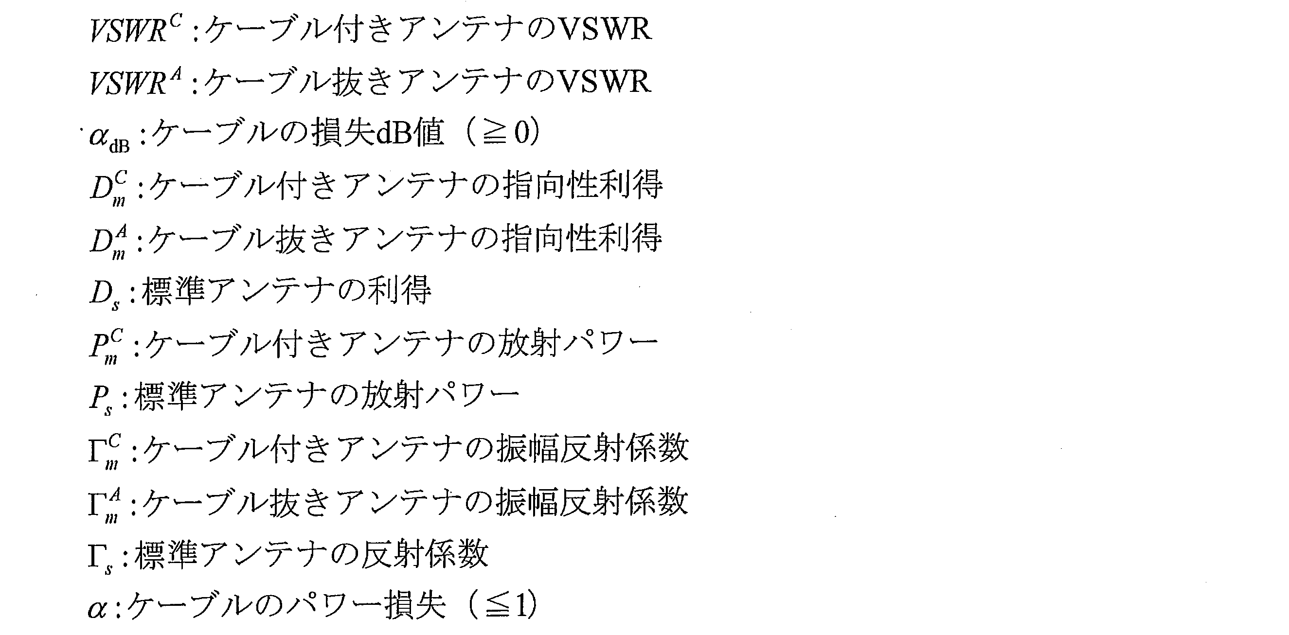
次に、本発明の実施の形態2について説明する。本実施の形態は、上記の実施の形態1に係るアンテナ装置101~101dにおいて、第1の放射部111~111dが有するメアンダ形状(メアンダ形状部)、及び、第2の放射部112~112dが有するメアンダ形状の少なくとも一方に、それぞれのメアンダ形状内において短絡箇所を発生させるための1つまたは複数の短絡部材(短絡部)を配置した実施の形態である。なお、短絡部材は、独立した部材として設けられる場合に限らず、例えば放射素子を形成する導電性経路を同じ材料により、導電性経路とともに形成されるものであってもよい。
図16は、図15に示したアンテナ装置101gのVSWR特性を示すグラフである。また、図17は、図15に示したアンテナ装置101gの550MHz帯域におけるxy面の放射パターンを示すグラフである。
図18は、図13に示したアンテナ装置101eの750MHz帯域におけるxy面の放射パターン、及び、図15に示したアンテナ装置101gの800MHz帯域におけるxy面の放射パターンを示すグラフである。
図19は、図14に示したアンテナ装置101fの700MHz帯域におけるxy面の放射パターン、図15に示したアンテナ装置101gの700MHz帯域におけるxy面の放射パターン、及び、図20に示したアンテナ装置101hの700MHz帯域におけるxy面の放射パターンを示すグラフである。
次に、本発明の実施の形態3について説明する。上述したように、地上波デジタル放送用のアンテナ装置が実用化されれば、その放送の受信端末となる、携帯電話、パーソナルコンピュータ、カーナビゲーションシステム、車載用テレビジョン受像機など多種多様な受信機に搭載されることになる。
図22は、メアンダ形状を有する放射素子315内に短絡部材331を配置して、放射素子315内に複数の導電性経路を生じさせた状態を示す模式図である。
この実験においては、図23に示すように、350mm×250mmの導体部材としての金属板403上に、誘電体層402を介してアンテナ装置401を搭載した。誘電体層402については後述する。なお、アンテナ装置401のサイズが100mm×50mm程度であれば、アンテナ装置401を350mm×250mmの導体部材上に搭載したときと概ね同じ特性が、アンテナ装置401を自動車のボンネット等の導体部材上に搭載した場合にも得られる。
発明者等は、図23に示すように、アンテナ装置401と導体部材としての金属板403との間に誘電体層402を設けることにより、アンテナ装置401と導体部材(金属板403)との間の距離を数mm程度に小さくしても実用に耐えるVSWR特性を有するアンテナ装置を実現できることを見出した。この際、誘電体層402の比誘電率εrは1以上10以下に設定することが望ましい。これは、比誘電率εrを10よりも大きくすると、放射効率の低下が無視できなくためである。
図28は、アンテナ装置201の変形例であるアンテナ装置201aを示している。以下、上記の実施の形態3と異なる部分について、その詳細な説明を行なうものとし、同様の部分については、説明を省略する。
発明者等は、上記の実施の形態3と同様、図23に示すように、350mm×250mmの金属板403上に、誘電体層402を介してアンテナ装置401を搭載した。
図32に、誘電体層402の厚さdを変化させ、各厚さdにおけるアンテナ装置401のVSWR特性の測定結果を示す。ここでは、図28のアンテナ装置201aをアンテナ装置401として用いている。
上述したように、地上波デジタル放送用のアンテナ装置が実用化されれば、受信端末としては、携帯電話の他、カーナビ、パソコン、専用ポータブルテレビなど多種多様な受信機に搭載することができる。
本発明のさらに他の実施の形態を図面に基づいて以下に説明する。
本発明のさらに他の実施の形態を図面に基づいて以下に説明する。
本実施の形態のアンテナシステムは、以上の各実施の形態に示したアンテナ装置701のうち、複数のアンテナ装置701をダイバシティ構成として使用している。本実施の形態において、アンテナシステムに使用する複数のアンテナ装置701は、全て同一構成のもの、互いに構成が異なるもの、あるいは少なくとも一つが異なる構成のもののいずれであってもよい。
111 第1の放射部(第1の部分)
112 第2の放射部(第2の部分)
113、113a~113g、211,211a 巻込部(第1の領域)
114、222,222a 給電部
115、215、215a 放射素子
116、116a~116d、116f~116h インダクタンス整合パターン(幅広部)
117、117a、117b、117c、117d 第1の根本部
117c1 第1の直線部(幅広部)
117c3 第2の直線部(後端直線部)
117d3 第2の直線部(後端直線部)
117o1 第1の直線部
117o5 第3の直線部(後端直線部)
117o11、117a11、117b11、117c11、117d11 凸部
118、118a、118b、118c、118d 第2の根本部
118a1 第4の直線部(幅広部)
118b1 第4の直線部(幅広部)
118d2 第2の屈曲部(幅広部)
118c3 第4の直線部(後端直線部)
118d3 第4の直線部(後端直線部)
118o1 第4の直線部(幅広部)
118o5 第6の直線部(後端直線部)
118o11 凸部(幅広部)
118a11、118b11、118c11、118d11 凸部
121、221、221a 同軸ケーブル
122 外部導体
123 内部導体
131g、132g、133g、134g、231、231a、232a 短絡部材(短絡部)
212,212a 放射部
213、213a 第1の幅広部
214、214a 第2の幅広部
402 誘電体
701 アンテナ装置
702 放電素子
703 アンテナシステム
711 誘電体層
802 金属材
803 内装材
901 自動車
902 車体
903 窓
Claims (15)
- 一端から他端に連続する導電性経路を有し、前記導電性経路の両端側に給電部が形成された放射素子を備えているアンテナ装置であって、
前記放射素子は、前記導電性経路の一端側である第1の根本部、前記導電性経路の他端側である第2の根本部、およびこれら第1の根本部と第2の根本部との間の中間部を有し、
前記給電部は、前記第1の根本部および前記第2の根本部に形成され、
前記第1の根本部および前記第2の根本部は、前記給電部を取り囲むように配置され、かつ前記導電性経路が形成されている領域のうちの一部の領域である第1の領域に形成され、
前記第1の領域における、前記第1の根本部と前記第2の根本部との前記中間部と直接接続されている後端直線部は互いに反対方向に延びており、
前記第1の根本部と前記第2の根本部との少なくとも一方には、前記給電部に接続される給電線と重畳する位置における幅が他の位置よりも広くなっている幅広部が形成されていることを特徴とするアンテナ装置。 - 前記中間部は、少なくとも1回の折り返しパターンからなるメアンダ形状を有する第1の部分と、直線形状または少なくとも1回の折り返しパターンからなるメアンダ形状を有する第2の部分とからなり、
前記第1の部分のメアンダ形状の折り返し方向と、前記第2の部分の直線形状の延在する方向またはメアンダ形状の折り返し方向とが、互いに直交するように配置されていることを特徴とする請求項1に記載のアンテナ装置。 - 前記放射素子は、前記第1の根本部が、前記放射素子の一方の端から第1の向きに伸びる第1の直線部と、第1の屈曲部を介して前記第1の直線部に連結され、前記第1の屈曲部から前記第1の向きとは逆向きの第2の向きに伸びる第2の直線部とを有し、前記第2の直線部が前記後端直線部となっており、
前記第2の根本部が、前記放射素子の他方の端から前記第2の向きに伸びる第3の直線部と、第2の屈曲部を介して前記第3の直線部に連結され、前記第2の屈曲部から前記第1の向きに伸びる第4の直線部とを有し、前記第4の直線部が前記後端直線部となっていることを特徴とする請求項1または2に記載のアンテナ装置。 - 前記放射素子は、前記第1の根本部が、前記放射素子の一方の端から第1の向きに伸びる第1の直線部と、第1の屈曲部を介して前記第1の直線部に連結され、前記第1の屈曲部から前記第1の向きとは逆向きの第2の向きに伸びる第2の直線部と、第2の屈曲部を介して前記第2の直線部に連結され、前記第2の屈曲部から前記第1の向きに伸びる第3の直線部とを有し、前記第3の直線部が前記後端直線部となっており
前記第2の根本部が、前記放射素子の他方の端から前記第2の向きに伸びる第4の直線部と、第3の屈曲部を介して前記第4の直線部に連結され、前記第3の屈曲部から前記第1の向きに伸びる第5の直線部と、第4の屈曲部を介して前記第5の直線部に連結され、前記第3の屈曲部から前記第2の向きに伸びる第6の直線部とを有し、前記第6の直線部が前記後端直線部となっていることを特徴とする請求項1または2に記載のアンテナ装置。 - 前記第1の部分及び前記第2の部分の少なくとも一方は、それぞれのメアンダ形状上に配置された1つまたは複数の短絡部材であって、それぞれのメアンダ形状内において短絡箇所を発生させるための1つまたは複数の短絡部材を有することを特徴とする請求項2から4のいずれか1項に記載のアンテナ装置。
- 前記放射素子の前記中間部は、前記導電性経路の複数回の折り返しパターンからなるメアンダ形状部を有し、
前記メアンダ形状部には、アンテナ装置の使用帯域内におけるVSWR値を低下させるように、前記折り返しパターンにおける異なる2点間を短絡させる短絡部が形成されていることを特徴とする請求項1に記載のアンテナ装置。 - 前記短絡部は、前記VSWR値を3.5以下に低下させるように、前記折り返しパターンにおける異なる2点間を短絡することを特徴とする請求項6に記載のアンテナ装置。
- 前記放射素子における一方の面の側には誘電体からなる誘電体層を備えていることを特徴とする請求項1から7のいずれか1項に記載のアンテナ装置。
- 前記誘電体の厚さは、2mm以上であることを特徴とする請求項8に記載のアンテナ装置。
- 請求項6に記載のアンテナ装置を備え、前記アンテナ装置が自動車の車内に配置されていることを特徴とするアンテナシステム。
- 前記アンテナ装置は、自動車の車体に形成された開口部から前記アンテナ装置の使用帯域における最低周波数の波長の1/2以下の距離の範囲に配置されていることを特徴とする請求項10に記載のアンテナシステム。
- 前記アンテナ装置は、自動車のピラーの位置、ルーフトップの裏の位置、ドアの内側の位置、またはダッシュボード上の位置のいずれかに配置されていることを特徴とする請求項10または11に記載のアンテナシステム。
- 請求項6に記載のアンテナ装置と、受信信号出力手段とを備え、前記アンテナ装置は、複数個が自動車の車体に配置され、前記受信信号出力手段は、前記複数個のアンテナ装置と接続され、前記複数個のアンテナ装置によりダイバシティを行うことを特徴とするアンテナシステム。
- 前記複数個のアンテナ装置は、少なくとも1個が自動車の車内と車外とにそれぞれ配置されていることを特徴とする請求項13に記載のアンテナシステム。
- 前記複数個のアンテナ装置の総数は2個以上かつ4個以下であることを特徴とする請求項13または14に記載のアンテナシステム。
Priority Applications (4)
| Application Number | Priority Date | Filing Date | Title |
|---|---|---|---|
| EP11732993.8A EP2506364A4 (en) | 2010-01-18 | 2011-01-17 | Antenna device and antenna system |
| JP2011550034A JP5688377B2 (ja) | 2010-01-18 | 2011-01-17 | アンテナ装置およびアンテナシステム |
| CN201180005592.0A CN102714356B (zh) | 2010-01-18 | 2011-01-17 | 天线装置以及天线系统 |
| US13/539,955 US9490527B2 (en) | 2010-01-18 | 2012-07-02 | Antenna device and antenna system |
Applications Claiming Priority (4)
| Application Number | Priority Date | Filing Date | Title |
|---|---|---|---|
| JP2010008440 | 2010-01-18 | ||
| JP2010-008440 | 2010-01-18 | ||
| JP2010-226081 | 2010-10-05 | ||
| JP2010226081 | 2010-10-05 |
Related Child Applications (1)
| Application Number | Title | Priority Date | Filing Date |
|---|---|---|---|
| US13/539,955 Continuation US9490527B2 (en) | 2010-01-18 | 2012-07-02 | Antenna device and antenna system |
Publications (1)
| Publication Number | Publication Date |
|---|---|
| WO2011087123A1 true WO2011087123A1 (ja) | 2011-07-21 |
Family
ID=44304393
Family Applications (1)
| Application Number | Title | Priority Date | Filing Date |
|---|---|---|---|
| PCT/JP2011/050675 Ceased WO2011087123A1 (ja) | 2010-01-18 | 2011-01-17 | アンテナ装置およびアンテナシステム |
Country Status (5)
| Country | Link |
|---|---|
| US (1) | US9490527B2 (ja) |
| EP (1) | EP2506364A4 (ja) |
| JP (1) | JP5688377B2 (ja) |
| CN (1) | CN102714356B (ja) |
| WO (1) | WO2011087123A1 (ja) |
Cited By (2)
| Publication number | Priority date | Publication date | Assignee | Title |
|---|---|---|---|---|
| JP2014075649A (ja) * | 2012-10-03 | 2014-04-24 | Kojima Press Industry Co Ltd | アンテナユニット |
| WO2025143027A1 (ja) * | 2023-12-25 | 2025-07-03 | 株式会社ヨコオ | アンテナ装置 |
Families Citing this family (9)
| Publication number | Priority date | Publication date | Assignee | Title |
|---|---|---|---|---|
| USD760205S1 (en) * | 2014-03-28 | 2016-06-28 | Lorom Industrial Co., Ltd. | Antenna for glass |
| USD795845S1 (en) * | 2014-11-15 | 2017-08-29 | Airgain Incorporated | Antenna |
| USD795227S1 (en) * | 2015-06-09 | 2017-08-22 | Airgain Incorporated | Antenna |
| USD801954S1 (en) * | 2015-08-07 | 2017-11-07 | Airgain Incorporated | Antenna |
| US11048786B2 (en) | 2016-04-13 | 2021-06-29 | AMI Research & Development, LLC | Techniques for fingerprint detection and user authentication |
| CN110506362A (zh) | 2016-12-12 | 2019-11-26 | Ami 研发有限责任公司 | 用于车辆的am / fm定向天线阵列 |
| DE102017213374B3 (de) * | 2017-08-02 | 2018-10-11 | Audi Ag | Antennenanordnung für ein Fahrzeug |
| EP4260405B1 (en) | 2020-12-10 | 2025-02-19 | PCI Private Limited | Printed dipole antenna |
| US20230050792A1 (en) * | 2021-08-13 | 2023-02-16 | Texas Instruments Incorporated | Monopole antenna design for improved rf antenna efficiency |
Citations (5)
| Publication number | Priority date | Publication date | Assignee | Title |
|---|---|---|---|---|
| JP2002280817A (ja) * | 2001-03-21 | 2002-09-27 | Hitachi Cable Ltd | 同軸ケーブル付小型アンテナ及びそれを用いた情報端末 |
| JP2004112044A (ja) * | 2002-09-13 | 2004-04-08 | Furukawa Electric Co Ltd:The | ループアンテナ |
| JP2005117268A (ja) * | 2003-10-06 | 2005-04-28 | Sony Corp | アンテナ装置及びアンテナ装置を備える携帯型情報端末装置 |
| JP2005347798A (ja) * | 2004-05-31 | 2005-12-15 | Maspro Denkoh Corp | ループアンテナ及びアンテナ装置 |
| JP2007116300A (ja) * | 2005-10-19 | 2007-05-10 | Fujitsu Ltd | タグアンテナ,これを用いるタグ及びrfidシステム。 |
Family Cites Families (16)
| Publication number | Priority date | Publication date | Assignee | Title |
|---|---|---|---|---|
| US6362784B1 (en) * | 1998-03-31 | 2002-03-26 | Matsuda Electric Industrial Co., Ltd. | Antenna unit and digital television receiver |
| SE512524C2 (sv) * | 1998-06-24 | 2000-03-27 | Allgon Ab | En antennanordning, en metod för framställning av en antennenordning och en radiokommunikationsanordning inkluderande en antennanordning |
| JP3639767B2 (ja) * | 1999-06-24 | 2005-04-20 | 株式会社村田製作所 | 表面実装型アンテナおよびそれを用いた通信機 |
| JP3824900B2 (ja) * | 2000-10-12 | 2006-09-20 | 古河電気工業株式会社 | アンテナ取付構造 |
| KR20040037127A (ko) | 2001-09-28 | 2004-05-04 | 미쓰비시 마테리알 가부시키가이샤 | 안테나 코일 및 그것을 이용한 rfid 용 태그,트랜스폰더용 안테나 |
| JP4196554B2 (ja) * | 2001-09-28 | 2008-12-17 | 三菱マテリアル株式会社 | タグ用アンテナコイル及びそれを用いたrfid用タグ |
| US7233298B2 (en) * | 2003-10-30 | 2007-06-19 | Wavetest Systems, Inc. | High performance antenna |
| JPWO2006059366A1 (ja) * | 2004-11-30 | 2008-06-05 | 株式会社日立超エル・エス・アイ・システムズ | 無線タグ装置 |
| JP4663346B2 (ja) * | 2005-02-01 | 2011-04-06 | 富士通株式会社 | メアンダラインアンテナ |
| JP4747988B2 (ja) * | 2006-08-07 | 2011-08-17 | 株式会社デンソー | 車載アンテナ装置およびその製造方法 |
| KR100797172B1 (ko) * | 2006-08-08 | 2008-01-23 | 삼성전자주식회사 | 정합회로가 일체로 형성된 루프 안테나 |
| TWI307565B (en) * | 2006-08-29 | 2009-03-11 | Univ Nat Sun Yat Sen | An internal meandered loop antenna for multiband operation |
| US8235299B2 (en) * | 2007-07-04 | 2012-08-07 | Murata Manufacturing Co., Ltd. | Wireless IC device and component for wireless IC device |
| WO2009110382A1 (ja) | 2008-03-03 | 2009-09-11 | 株式会社村田製作所 | 複合アンテナ |
| JP5267463B2 (ja) | 2008-03-03 | 2013-08-21 | 株式会社村田製作所 | 無線icデバイス及び無線通信システム |
| JP2009246844A (ja) | 2008-03-31 | 2009-10-22 | Asahi Glass Co Ltd | 自動車用高周波ガラスアンテナ及び自動車用の窓ガラス板 |
-
2011
- 2011-01-17 WO PCT/JP2011/050675 patent/WO2011087123A1/ja not_active Ceased
- 2011-01-17 EP EP11732993.8A patent/EP2506364A4/en not_active Withdrawn
- 2011-01-17 JP JP2011550034A patent/JP5688377B2/ja not_active Expired - Fee Related
- 2011-01-17 CN CN201180005592.0A patent/CN102714356B/zh not_active Expired - Fee Related
-
2012
- 2012-07-02 US US13/539,955 patent/US9490527B2/en not_active Expired - Fee Related
Patent Citations (5)
| Publication number | Priority date | Publication date | Assignee | Title |
|---|---|---|---|---|
| JP2002280817A (ja) * | 2001-03-21 | 2002-09-27 | Hitachi Cable Ltd | 同軸ケーブル付小型アンテナ及びそれを用いた情報端末 |
| JP2004112044A (ja) * | 2002-09-13 | 2004-04-08 | Furukawa Electric Co Ltd:The | ループアンテナ |
| JP2005117268A (ja) * | 2003-10-06 | 2005-04-28 | Sony Corp | アンテナ装置及びアンテナ装置を備える携帯型情報端末装置 |
| JP2005347798A (ja) * | 2004-05-31 | 2005-12-15 | Maspro Denkoh Corp | ループアンテナ及びアンテナ装置 |
| JP2007116300A (ja) * | 2005-10-19 | 2007-05-10 | Fujitsu Ltd | タグアンテナ,これを用いるタグ及びrfidシステム。 |
Non-Patent Citations (2)
| Title |
|---|
| J.D. KRAUS; R.J. MARHEFKA: "Antennas For All Applications", 2002, MCGRAW HILL, pages: 178 - 181 |
| See also references of EP2506364A4 |
Cited By (2)
| Publication number | Priority date | Publication date | Assignee | Title |
|---|---|---|---|---|
| JP2014075649A (ja) * | 2012-10-03 | 2014-04-24 | Kojima Press Industry Co Ltd | アンテナユニット |
| WO2025143027A1 (ja) * | 2023-12-25 | 2025-07-03 | 株式会社ヨコオ | アンテナ装置 |
Also Published As
| Publication number | Publication date |
|---|---|
| EP2506364A4 (en) | 2017-09-13 |
| JPWO2011087123A1 (ja) | 2013-05-20 |
| CN102714356B (zh) | 2015-07-29 |
| US9490527B2 (en) | 2016-11-08 |
| JP5688377B2 (ja) | 2015-03-25 |
| CN102714356A (zh) | 2012-10-03 |
| US20120268332A1 (en) | 2012-10-25 |
| EP2506364A1 (en) | 2012-10-03 |
Similar Documents
| Publication | Publication Date | Title |
|---|---|---|
| JP5688377B2 (ja) | アンテナ装置およびアンテナシステム | |
| JP5446536B2 (ja) | ガラスアンテナ | |
| JP5779189B2 (ja) | アンテナ装置およびアンテナ装置を搭載した移動体 | |
| JP5690842B2 (ja) | アンテナ一体型ハーネス | |
| KR100954379B1 (ko) | 루프 안테나 | |
| EP2434579B1 (en) | Antenna device | |
| JP5018946B2 (ja) | アンテナ | |
| KR20100106917A (ko) | 수신 장치 | |
| WO2008051055A1 (en) | Monopole antenna | |
| JP2012028906A (ja) | アンテナ装置 | |
| JP4586028B2 (ja) | 無給電素子を用いる多帯域アンテナ | |
| WO2011062272A1 (ja) | アンテナ装置 | |
| JP5443088B2 (ja) | ダイポールアンテナ装置 | |
| CN101107749A (zh) | 带广播用接收器的便携电话 | |
| JP5633295B2 (ja) | 車両用アンテナ | |
| KR100958812B1 (ko) | 다중공진 안테나 및 이를 갖는 휴대용 전자기기 | |
| CN103117448B (zh) | 复合螺旋天线 | |
| JP5532942B2 (ja) | ガラスアンテナ | |
| JP2013123122A (ja) | 広帯域小型アンテナ | |
| JP5648653B2 (ja) | アンテナ | |
| JP2008153816A (ja) | アンテナおよびアンテナ装置 | |
| JP4929799B2 (ja) | アンテナ装置 | |
| WO2012067241A1 (ja) | 無線装置および無線装置を備えた移動体 | |
| KR100924127B1 (ko) | 방송전용 내장형 프랙탈 안테나 |
Legal Events
| Date | Code | Title | Description |
|---|---|---|---|
| WWE | Wipo information: entry into national phase |
Ref document number: 201180005592.0 Country of ref document: CN |
|
| 121 | Ep: the epo has been informed by wipo that ep was designated in this application |
Ref document number: 11732993 Country of ref document: EP Kind code of ref document: A1 |
|
| REEP | Request for entry into the european phase |
Ref document number: 2011732993 Country of ref document: EP |
|
| WWE | Wipo information: entry into national phase |
Ref document number: 2011550034 Country of ref document: JP Ref document number: 2011732993 Country of ref document: EP |
|
| NENP | Non-entry into the national phase |
Ref country code: DE |