WO2011089708A1 - バッテリ充電制御システム - Google Patents
バッテリ充電制御システム Download PDFInfo
- Publication number
- WO2011089708A1 WO2011089708A1 PCT/JP2010/050788 JP2010050788W WO2011089708A1 WO 2011089708 A1 WO2011089708 A1 WO 2011089708A1 JP 2010050788 W JP2010050788 W JP 2010050788W WO 2011089708 A1 WO2011089708 A1 WO 2011089708A1
- Authority
- WO
- WIPO (PCT)
- Prior art keywords
- battery
- power
- maximum
- charging
- alternator
- Prior art date
- Legal status (The legal status is an assumption and is not a legal conclusion. Google has not performed a legal analysis and makes no representation as to the accuracy of the status listed.)
- Ceased
Links
Images




Classifications
-
- H—ELECTRICITY
- H02—GENERATION; CONVERSION OR DISTRIBUTION OF ELECTRIC POWER
- H02J—ELECTRIC POWER NETWORKS; CIRCUIT ARRANGEMENTS OR SYSTEMS FOR SUPPLYING OR DISTRIBUTING ELECTRIC POWER; SYSTEMS FOR STORING ELECTRIC ENERGY
- H02J7/00—Circuit arrangements for charging or discharging batteries or for supplying loads from batteries
- H02J7/14—Circuit arrangements for charging or discharging batteries or for supplying loads from batteries for charging batteries from dynamo-electric generators driven at varying speed, e.g. on vehicle
- H02J7/1423—Circuit arrangements for charging or discharging batteries or for supplying loads from batteries for charging batteries from dynamo-electric generators driven at varying speed, e.g. on vehicle with multiple batteries
-
- Y—GENERAL TAGGING OF NEW TECHNOLOGICAL DEVELOPMENTS; GENERAL TAGGING OF CROSS-SECTIONAL TECHNOLOGIES SPANNING OVER SEVERAL SECTIONS OF THE IPC; TECHNICAL SUBJECTS COVERED BY FORMER USPC CROSS-REFERENCE ART COLLECTIONS [XRACs] AND DIGESTS
- Y02—TECHNOLOGIES OR APPLICATIONS FOR MITIGATION OR ADAPTATION AGAINST CLIMATE CHANGE
- Y02T—CLIMATE CHANGE MITIGATION TECHNOLOGIES RELATED TO TRANSPORTATION
- Y02T10/00—Road transport of goods or passengers
- Y02T10/60—Other road transportation technologies with climate change mitigation effect
- Y02T10/70—Energy storage systems for electromobility, e.g. batteries
Definitions
- the battery charge control system of the present invention has priority over the battery selected by the selection means when there is an insufficiently charged battery whose charge state is lower than a predetermined lower limit value among the plurality of batteries.
- a battery with insufficient charge may be charged.
- the lower limit here is preferably set to a value slightly larger than the minimum value of the predetermined range. According to such a battery charge control system, a situation in which the state of charge of each battery falls below the minimum value in the predetermined range is avoided, so that a reduction in battery life is suppressed.
- the battery charge control system of the present invention may control the alternator so as to charge a battery having the second largest chargeable power when charging of the battery selected by the selection unit is prohibited. In that case, the charging power can be increased as much as possible within a range in which a decrease in battery life can be suppressed.
- the charging power can be increased as much as possible in the battery charging control system that selectively charges the generated power of the alternator to a plurality of batteries.
- the ECU20 changes the generated voltage of the alternator 101 by duty-controlling on / off of the regulator 101a. For example, when increasing the power generation voltage of the alternator 101, the ECU 20 determines the duty ratio so that the regulator 101a has a long on-time (short off-time). On the other hand, when lowering the generated voltage of the alternator 101, the ECU 20 determines the duty ratio so that the ON time of the regulator 101a is short (off time is long). Further, the ECU 20 senses the actual power generation voltage of the alternator 101, and also performs feedback control of the duty ratio according to the difference between the actual power generation voltage and the target power generation voltage.
- the rotor of the alternator 101 is rotated by the kinetic energy transmitted from the drive wheels 6 to the internal combustion engine 1. At that time, if a field current is applied to the alternator 101, the kinetic energy of the drive wheels 6 can be converted into electric energy (regenerative power generation).
- the maximum generated power Wh that can be generated by the alternator 101 at a voltage Vh suitable for charging the high voltage battery 102 (hereinafter referred to as “high charge voltage”), and suitable for charging the low voltage battery 103.
- a method of performing regenerative power generation by selecting the larger one of the maximum generated power Wl that can be generated by the alternator 101 at a voltage (hereinafter referred to as “low charge voltage”) Vl is conceivable.
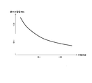
- FIG. 3 is a diagram showing the relationship between the maximum generated power of the alternator 101 and the rotational speed.
- the solid line in FIG. 3 indicates the maximum generated power Wh when the alternator 101 generates power with the high charge voltage Vh, and the dashed line in FIG. 3 indicates the maximum power generation when the alternator 101 generates power with the low charge voltage Vl. Electric power Wl is shown.
- the ECU 20 obtains electric power (chargeable power) Wph and Wpl that can be supplied (charged) from the alternator 101 to each of the batteries 102 and 103, and the chargeable electric power Wph and Wpl.
- the batteries 102 and 103 to be charged are selected according to the size relationship. Specifically, the ECU 20 selects a battery having a higher chargeable power Wph, Wpl from the high voltage battery 102 and the low voltage battery 103. When a battery to be charged is selected by such a method, the kinetic energy recovered by regenerative power generation becomes as large as possible.
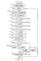
- the ECU 20 first acquires the traveling state of the vehicle from the output signals of the accelerator position sensor 21 and the vehicle speed sensor 25 in S101.
- the ECU 20 determines whether or not the traveling state of the vehicle is in a deceleration state. If a negative determination is made in S102, the ECU 20 once ends the execution of this routine. On the other hand, if an affirmative determination is made in S102, the ECU 20 proceeds to S103.
- the ECU 20 may calculate the maximum charging power Wch and Wcl based on the relationship between the magnitude of the internal resistance of the batteries 102 and 103 and the charging state. At that time, since the magnitude of the internal resistance of the batteries 102 and 103 changes depending on the temperature, the magnitude of the internal resistance of the batteries 102 and 103 is determined using the output signals of the first temperature sensor 102b and the second temperature sensor 103b as parameters. It may be corrected.
- the ECU 20 compares the chargeable powers Wph and Wpl obtained in S107. Specifically, the ECU 20 determines whether or not the chargeable power Wph of the high voltage battery 102 is greater than the chargeable power Wpl of the low voltage battery 103.
- the ECU 20 proceeds to S109 and executes a process for charging the high-voltage battery 102. Specifically, the ECU 20 controls the duty of the regulator 101a so that the generated voltage of the alternator 101 matches the high charging voltage Vh, and sets the changeover switch 104 so that the input terminal 104a and the first output terminal 104b are connected. Control.
- the ECU20 progresses to S111, after performing the process of above-mentioned S109 or S110.
- S111 the ECU 20 determines whether or not a regenerative power generation stop condition is satisfied.
- the regenerative power generation stop condition is satisfied when the traveling state of the vehicle shifts from the deceleration state to the non-deceleration state.
- the ECU 20 performs the regenerative power generation control according to the routine of FIG. 6, the kinetic energy recovered by the regenerative power generation can be increased as much as possible. As a result, the power charged in the high voltage battery 102 or the low voltage battery 103 is increased as much as possible.
- the difference between the first embodiment described above and the present embodiment is that regenerative power generation control is performed so that the state of charge of each of the batteries 102 and 103 is within an allowable range.
- Batteries 102 and 103 composed of lead-acid batteries, nickel-metal hydride batteries, lithium ion batteries, etc. have a reduced life when used (charged or discharged) in an excessively high or excessively low state of charge. There is.
- the charging power can be increased as much as possible within a range in which the lifetime reduction of the batteries 102 and 103 can be suppressed.
- FIG. 7 is a flowchart showing a regenerative power generation control routine.
- the same reference numerals are assigned to the same processes as those in the first embodiment (see FIG. 6).
- the ECU 20 determines whether or not the output signal SOC2 of the second SOC sensor 103a read in S104 is equal to or greater than the lower limit SOC2min.
- the lower limit SOC2min is a value that is slightly higher than the lowest value of the state of charge considered that the life of the low-voltage battery 103 can be reduced, and is determined in advance by an adaptation process using experiments or the like.
- the ECU 20 determines whether or not the output signal SOC1 of the first SOC sensor 102a read in S104 is equal to or lower than the upper limit value SOC1max.
- the upper limit SOC1max is a value that is slightly lower than the maximum value of the state of charge considered that the life of the high-voltage battery 102 can be reduced, and is determined in advance by an adaptation process using experiments or the like.
- S203 If a negative determination is made in S203 (SOC1> SOC1max), the ECU 20 proceeds to S110 and preferentially charges the low voltage battery 103. On the other hand, when an affirmative determination is made in S203 (SOC1 ⁇ SOC1max), the ECU 20 proceeds to S204.
- the ECU 20 determines whether or not the output signal SOC2 of the second SOC sensor 103a read in S104 is equal to or lower than the upper limit value SOC2max.
- the upper limit SOC2max is a value slightly lower than the maximum value of the state of charge considered that the life of the low-voltage battery 103 can be reduced, and is determined in advance by an adaptation process using experiments or the like.
Landscapes
- Engineering & Computer Science (AREA)
- Power Engineering (AREA)
- Charge And Discharge Circuits For Batteries Or The Like (AREA)
- Control Of Charge By Means Of Generators (AREA)
- Secondary Cells (AREA)
Abstract
Description
車両の原動機または車輪の運動エネルギを利用して作動し、発電電圧を変更可能なオルタネータと、
充電電圧が相違する複数のバッテリと、
前記オルタネータの回転数をパラメータとして、各バッテリに適した充電電圧において前記オルタネータが発電可能な最大の発電電力である最大発電電力を演算する第1演算手段と、
各バッテリの充電状態をパラメータとして、各バッテリが受ける入れることができる最大の充電電力である最大充電電力を演算する第2演算手段と、
前記最大発電電力および前記最大充電電力を比較して、前記オルタネータから各バッテリへ供給可能な電力である充電可能電力を取得する取得手段と、
前記複数のバッテリのうち、前記取得手段が取得した充電可能電力が最も大きいバッテリを選択する選択手段と、
前記選択手段により選択されたバッテリが充電されるように前記オルタネータを制御する制御手段と、
を備えるようにした。
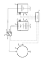
先ず、本発明の第1の実施例について図1乃至図6に基づいて説明する。図1は、本発明が適用される車輌の概略構成を示す図である。
次に、本発明の第2の実施例について図7に基づいて説明する。ここでは、前述した第1の実施例と異なる構成について説明し、同様の構成については説明を省略する。
2 トランスミッション
3 プロペラシャフト
4 デファレンシャルギア
5 ドライブシャフト
6 駆動輪
21 アクセルポジションセンサ
22 シフトポジションセンサ
23 ブレーキスイッチ
24 クランクポジションセンサ
25 車速センサ
100 充電機構
101 オルタネータ
101a レギュレータ
102 高電圧バッテリ
102a 第1SOCセンサ
102b 第1温度センサ
103 低電圧バッテリ
103 低電圧バッテリ
103a 第2SOCセンサ
103b 第2温度センサ
104 切換スイッチ
104a 入力端子
104b 第1出力端子
104c 第2出力端子
Claims (6)
- 車両の原動機または車輪の運動エネルギを利用して作動し、発電電圧を変更可能なオルタネータと、
充電電圧が相違する複数のバッテリと、
前記オルタネータの回転数をパラメータとして、各バッテリに適した充電電圧において前記オルタネータが発電可能な最大の発電電力である最大発電電力を演算する第1演算手段と、
各バッテリの充電状態をパラメータとして、各バッテリが受け入れることができる最大の充電電力である最大充電電力を演算する第2演算手段と、
前記最大発電電力および前記最大充電電力を比較して、前記オルタネータから各バッテリへ供給可能な電力である充電可能電力を取得する取得手段と、
前記複数のバッテリのうち、前記取得手段が取得した充電可能電力が最も大きいバッテリを選択する選択手段と、
前記選択手段により選択されたバッテリが充電されるように前記オルタネータを制御する制御手段と、
を備えることを特徴とするバッテリ充電制御システム。 - 請求項1において、前記取得手段は、前記最大発電電力または前記最大充電電力の何れか小さい方を充電可能電力として取得することを特徴とするバッテリ充電制御システム。
- 請求項1または2において、前記した各バッテリの温度を検出する検出手段と、
前記検出手段が検出した温度に応じて前記第2演算手段が算出した最大充電電力を補正する補正手段と、をさらに備え、
前記取得手段は、前記第1演算手段により算出された最大発電電力と前記補正手段により補正された最大充電電力とを比較することにより、各バッテリの充電可能電力を取得することを特徴とするバッテリ充電制御システム。 - 請求項1乃至3の何れか1項において、前記した複数のバッテリのうち、充電状態が予め定めた下限値を下回る充電不足のバッテリが存在する場合は、前記制御手段は、充電不足のバッテリが前記選択手段により選択されたバッテリに優先して充電されるように前記オルタネータを制御することを特徴とするバッテリ充電制御システム。
- 請求項1乃至4の何れか1項において、前記選択手段により選択されたバッテリの充電状態が予め定められた上限値を上回っている場合は、前記制御手段は、前記選択手段により選択されたバッテリの充電を禁止することを特徴とするバッテリ充電制御システム。
- 請求項5において、前記制御手段は、前記複数のバッテリのうち、前記取得手段が取得した充電可能電力が2番目に大きなバッテリを充電するように、前記オルタネータを制御することを特徴とするバッテリ充電制御システム。
Priority Applications (5)
| Application Number | Priority Date | Filing Date | Title |
|---|---|---|---|
| EP10843874.8A EP2528189B1 (en) | 2010-01-22 | 2010-01-22 | Battery charging control system |
| CN201080061282.6A CN102714425B (zh) | 2010-01-22 | 2010-01-22 | 电池充电控制系统 |
| US13/519,709 US8917058B2 (en) | 2010-01-22 | 2010-01-22 | Battery charging control system |
| JP2011550757A JP5459321B2 (ja) | 2010-01-22 | 2010-01-22 | バッテリ充電制御システム |
| PCT/JP2010/050788 WO2011089708A1 (ja) | 2010-01-22 | 2010-01-22 | バッテリ充電制御システム |
Applications Claiming Priority (1)
| Application Number | Priority Date | Filing Date | Title |
|---|---|---|---|
| PCT/JP2010/050788 WO2011089708A1 (ja) | 2010-01-22 | 2010-01-22 | バッテリ充電制御システム |
Publications (1)
| Publication Number | Publication Date |
|---|---|
| WO2011089708A1 true WO2011089708A1 (ja) | 2011-07-28 |
Family
ID=44306530
Family Applications (1)
| Application Number | Title | Priority Date | Filing Date |
|---|---|---|---|
| PCT/JP2010/050788 Ceased WO2011089708A1 (ja) | 2010-01-22 | 2010-01-22 | バッテリ充電制御システム |
Country Status (5)
| Country | Link |
|---|---|
| US (1) | US8917058B2 (ja) |
| EP (1) | EP2528189B1 (ja) |
| JP (1) | JP5459321B2 (ja) |
| CN (1) | CN102714425B (ja) |
| WO (1) | WO2011089708A1 (ja) |
Cited By (2)
| Publication number | Priority date | Publication date | Assignee | Title |
|---|---|---|---|---|
| JP2012165589A (ja) * | 2011-02-08 | 2012-08-30 | Toyota Motor Corp | 車両の発電制御システム |
| JP2016117354A (ja) * | 2014-12-19 | 2016-06-30 | トヨタ自動車株式会社 | 電源管理装置 |
Families Citing this family (14)
| Publication number | Priority date | Publication date | Assignee | Title |
|---|---|---|---|---|
| KR101251243B1 (ko) * | 2011-10-27 | 2013-04-08 | 엘에스산전 주식회사 | 전기자동차의 전원 공급 시스템 |
| US9083202B2 (en) * | 2012-12-18 | 2015-07-14 | Fca Us Llc | Alternator control for battery charging |
| JP2014158414A (ja) | 2013-01-21 | 2014-08-28 | Semiconductor Energy Lab Co Ltd | 蓄電体を有する車両 |
| DE102014106959A1 (de) * | 2013-05-20 | 2014-11-20 | Kyung Chang Industrial Co., Ltd. | Eine plötzliche Beschleunigung verhinderndes elektronisches Gaspedal und Verfahren hiervon |
| JP6301240B2 (ja) * | 2014-02-07 | 2018-03-28 | 本田技研工業株式会社 | 車両用バッテリ充電装置 |
| KR101684736B1 (ko) * | 2014-08-21 | 2016-12-08 | 에스케이이노베이션 주식회사 | 전력 소모를 최소화한 과충전 방지 장치 |
| JP2018029407A (ja) * | 2014-12-25 | 2018-02-22 | 三洋電機株式会社 | 電池パック |
| CN116080381A (zh) | 2016-01-29 | 2023-05-09 | 株式会社半导体能源研究所 | 轮毂及移动体 |
| KR20180005008A (ko) * | 2016-07-05 | 2018-01-15 | 현대자동차주식회사 | 환경차량용 배터리 과충전 방지장치 |
| JP7147621B2 (ja) * | 2019-02-20 | 2022-10-05 | トヨタ自動車株式会社 | 充電制御装置及び方法 |
| CN112124316B (zh) * | 2019-06-25 | 2022-09-13 | 北京车和家信息技术有限公司 | 扭矩限值的确定方法和装置 |
| JP7074725B2 (ja) * | 2019-07-18 | 2022-05-24 | 矢崎総業株式会社 | 電源システム、dcdcコンバータ装置、及び充電方法 |
| JP2021160665A (ja) * | 2020-04-02 | 2021-10-11 | ヤマハ発動機株式会社 | 船舶のバッテリの制御装置および制御方法、船舶 |
| CN112829582A (zh) * | 2021-02-20 | 2021-05-25 | 上海花豹科技有限公司 | 一种车辆发电系统及发电方法 |
Citations (4)
| Publication number | Priority date | Publication date | Assignee | Title |
|---|---|---|---|---|
| JPH01126136A (ja) * | 1987-11-09 | 1989-05-18 | Nippon Denso Co Ltd | 車両の充電装置 |
| JP2000184613A (ja) * | 1998-12-11 | 2000-06-30 | Shindengen Electric Mfg Co Ltd | 多出力バッテリ充電装置 |
| JP2000350379A (ja) | 1999-06-01 | 2000-12-15 | Nissan Motor Co Ltd | オルタネータシステム |
| JP2007227321A (ja) | 2006-02-27 | 2007-09-06 | Fujitsu Ten Ltd | バッテリ充電装置 |
Family Cites Families (13)
| Publication number | Priority date | Publication date | Assignee | Title |
|---|---|---|---|---|
| US4188527A (en) * | 1977-12-21 | 1980-02-12 | Ford Motor Company | Automotive electric quick heat system |
| US5057763A (en) * | 1988-09-12 | 1991-10-15 | Nippondenso Co., Ltd. | High power supply for motor vehicle |
| JPH06225599A (ja) * | 1992-10-14 | 1994-08-12 | Ford Motor Co | 自動車用発電機の出力電力制御装置 |
| US7256516B2 (en) * | 2000-06-14 | 2007-08-14 | Aerovironment Inc. | Battery charging system and method |
| JP3595252B2 (ja) * | 2000-09-06 | 2004-12-02 | 三菱電機株式会社 | 車両用電源システム |
| JP2004222473A (ja) * | 2003-01-17 | 2004-08-05 | Toyota Motor Corp | 車両用電源システム及び充電方法 |
| JP4385659B2 (ja) * | 2003-06-17 | 2009-12-16 | ソニー株式会社 | 充電回路およびそれを用いた充電装置 |
| CN1263629C (zh) * | 2003-11-04 | 2006-07-12 | 清华大学 | 燃料电池混合动力系统的功率分配方法 |
| JP5089883B2 (ja) * | 2005-12-16 | 2012-12-05 | 日立ビークルエナジー株式会社 | 蓄電池管理装置 |
| JP2007228753A (ja) * | 2006-02-24 | 2007-09-06 | Toyota Motor Corp | 電動車両 |
| US7459874B2 (en) * | 2007-02-20 | 2008-12-02 | Gm Global Technology Operations, Inc. | System and method for controlling electric drive systems |
| JP4274382B2 (ja) * | 2007-03-02 | 2009-06-03 | 株式会社日本自動車部品総合研究所 | 車両用二次電池の内部抵抗算出方法 |
| US20110227525A1 (en) * | 2010-01-16 | 2011-09-22 | Triune Ip Llc | Charging Circuit, Method, and System |
-
2010
- 2010-01-22 WO PCT/JP2010/050788 patent/WO2011089708A1/ja not_active Ceased
- 2010-01-22 EP EP10843874.8A patent/EP2528189B1/en active Active
- 2010-01-22 US US13/519,709 patent/US8917058B2/en active Active
- 2010-01-22 JP JP2011550757A patent/JP5459321B2/ja active Active
- 2010-01-22 CN CN201080061282.6A patent/CN102714425B/zh active Active
Patent Citations (4)
| Publication number | Priority date | Publication date | Assignee | Title |
|---|---|---|---|---|
| JPH01126136A (ja) * | 1987-11-09 | 1989-05-18 | Nippon Denso Co Ltd | 車両の充電装置 |
| JP2000184613A (ja) * | 1998-12-11 | 2000-06-30 | Shindengen Electric Mfg Co Ltd | 多出力バッテリ充電装置 |
| JP2000350379A (ja) | 1999-06-01 | 2000-12-15 | Nissan Motor Co Ltd | オルタネータシステム |
| JP2007227321A (ja) | 2006-02-27 | 2007-09-06 | Fujitsu Ten Ltd | バッテリ充電装置 |
Cited By (2)
| Publication number | Priority date | Publication date | Assignee | Title |
|---|---|---|---|---|
| JP2012165589A (ja) * | 2011-02-08 | 2012-08-30 | Toyota Motor Corp | 車両の発電制御システム |
| JP2016117354A (ja) * | 2014-12-19 | 2016-06-30 | トヨタ自動車株式会社 | 電源管理装置 |
Also Published As
| Publication number | Publication date |
|---|---|
| CN102714425B (zh) | 2015-01-07 |
| EP2528189A1 (en) | 2012-11-28 |
| EP2528189A4 (en) | 2017-04-19 |
| US20120293124A1 (en) | 2012-11-22 |
| EP2528189B1 (en) | 2018-11-28 |
| JPWO2011089708A1 (ja) | 2013-05-20 |
| JP5459321B2 (ja) | 2014-04-02 |
| US8917058B2 (en) | 2014-12-23 |
| CN102714425A (zh) | 2012-10-03 |
Similar Documents
| Publication | Publication Date | Title |
|---|---|---|
| JP5459321B2 (ja) | バッテリ充電制御システム | |
| US9415698B2 (en) | Hybrid vehicle | |
| US9751523B2 (en) | Hybrid vehicle | |
| US9550432B2 (en) | Hybrid vehicle having mode of increasing amount of charge stored in power storage device to target value and control method for hybrid vehicle | |
| JP4026013B2 (ja) | トルク制御装置 | |
| US10160444B2 (en) | Vehicle | |
| JP5382202B2 (ja) | 車両の回生制御システム | |
| JP2007212298A (ja) | 二次電池の残存容量推定装置 | |
| US9252630B2 (en) | Battery charge control apparatus | |
| JP5741153B2 (ja) | 充電制御装置 | |
| US20170151880A1 (en) | Battery system of electrically powered vehicle | |
| JP5344090B2 (ja) | 車両の回生制御システム | |
| US10919516B2 (en) | Hybrid vehicle | |
| JP5533716B2 (ja) | 車両の発電制御システム | |
| JP2008228429A (ja) | ハイブリッド車両の制御装置 | |
| JP5092903B2 (ja) | 車両用電池の充放電制御装置 | |
| JP2017103971A (ja) | バッテリーの制御システム、ハイブリッド車両及びバッテリーの制御方法 | |
| JP2013142568A (ja) | 二次電池および二次電池の残存容量算出装置 | |
| JP2013006430A (ja) | ハイブリッド車両およびその制御方法 | |
| JP4680949B2 (ja) | 電動車両の制御装置 | |
| JP4438442B2 (ja) | 車両の充放電制御装置 |
Legal Events
| Date | Code | Title | Description |
|---|---|---|---|
| WWE | Wipo information: entry into national phase |
Ref document number: 201080061282.6 Country of ref document: CN |
|
| 121 | Ep: the epo has been informed by wipo that ep was designated in this application |
Ref document number: 10843874 Country of ref document: EP Kind code of ref document: A1 |
|
| WWE | Wipo information: entry into national phase |
Ref document number: 13519709 Country of ref document: US |
|
| WWE | Wipo information: entry into national phase |
Ref document number: 2011550757 Country of ref document: JP |
|
| WWE | Wipo information: entry into national phase |
Ref document number: 2010843874 Country of ref document: EP |
|
| NENP | Non-entry into the national phase |
Ref country code: DE |