WO2011092806A1 - 車両およびその制御方法 - Google Patents
車両およびその制御方法 Download PDFInfo
- Publication number
- WO2011092806A1 WO2011092806A1 PCT/JP2010/051011 JP2010051011W WO2011092806A1 WO 2011092806 A1 WO2011092806 A1 WO 2011092806A1 JP 2010051011 W JP2010051011 W JP 2010051011W WO 2011092806 A1 WO2011092806 A1 WO 2011092806A1
- Authority
- WO
- WIPO (PCT)
- Prior art keywords
- driving force
- shift stage
- switch
- vehicle
- turned
- Prior art date
- Legal status (The legal status is an assumption and is not a legal conclusion. Google has not performed a legal analysis and makes no representation as to the accuracy of the status listed.)
- Ceased
Links
Images


Classifications
-
- B—PERFORMING OPERATIONS; TRANSPORTING
- B60—VEHICLES IN GENERAL
- B60K—ARRANGEMENT OR MOUNTING OF PROPULSION UNITS OR OF TRANSMISSIONS IN VEHICLES; ARRANGEMENT OR MOUNTING OF PLURAL DIVERSE PRIME-MOVERS IN VEHICLES; AUXILIARY DRIVES FOR VEHICLES; INSTRUMENTATION OR DASHBOARDS FOR VEHICLES; ARRANGEMENTS IN CONNECTION WITH COOLING, AIR INTAKE, GAS EXHAUST OR FUEL SUPPLY OF PROPULSION UNITS IN VEHICLES
- B60K6/00—Arrangement or mounting of plural diverse prime-movers for mutual or common propulsion, e.g. hybrid propulsion systems comprising electric motors and internal combustion engines
- B60K6/20—Arrangement or mounting of plural diverse prime-movers for mutual or common propulsion, e.g. hybrid propulsion systems comprising electric motors and internal combustion engines the prime-movers consisting of electric motors and internal combustion engines, e.g. HEVs
- B60K6/42—Arrangement or mounting of plural diverse prime-movers for mutual or common propulsion, e.g. hybrid propulsion systems comprising electric motors and internal combustion engines the prime-movers consisting of electric motors and internal combustion engines, e.g. HEVs characterised by the architecture of the hybrid electric vehicle
- B60K6/44—Series-parallel type
- B60K6/445—Differential gearing distribution type
-
- B—PERFORMING OPERATIONS; TRANSPORTING
- B60—VEHICLES IN GENERAL
- B60W—CONJOINT CONTROL OF VEHICLE SUB-UNITS OF DIFFERENT TYPE OR DIFFERENT FUNCTION; CONTROL SYSTEMS SPECIALLY ADAPTED FOR HYBRID VEHICLES; ROAD VEHICLE DRIVE CONTROL SYSTEMS FOR PURPOSES NOT RELATED TO THE CONTROL OF A PARTICULAR SUB-UNIT
- B60W20/00—Control systems specially adapted for hybrid vehicles
- B60W20/30—Control strategies involving selection of transmission gear ratio
-
- B—PERFORMING OPERATIONS; TRANSPORTING
- B60—VEHICLES IN GENERAL
- B60L—PROPULSION OF ELECTRICALLY-PROPELLED VEHICLES; SUPPLYING ELECTRIC POWER FOR AUXILIARY EQUIPMENT OF ELECTRICALLY-PROPELLED VEHICLES; ELECTRODYNAMIC BRAKE SYSTEMS FOR VEHICLES IN GENERAL; MAGNETIC SUSPENSION OR LEVITATION FOR VEHICLES; MONITORING OPERATING VARIABLES OF ELECTRICALLY-PROPELLED VEHICLES; ELECTRIC SAFETY DEVICES FOR ELECTRICALLY-PROPELLED VEHICLES
- B60L15/00—Methods, circuits, or devices for controlling the traction-motor speed of electrically-propelled vehicles
- B60L15/20—Methods, circuits, or devices for controlling the traction-motor speed of electrically-propelled vehicles for control of the vehicle or its driving motor to achieve a desired performance, e.g. speed, torque, programmed variation of speed
- B60L15/2054—Methods, circuits, or devices for controlling the traction-motor speed of electrically-propelled vehicles for control of the vehicle or its driving motor to achieve a desired performance, e.g. speed, torque, programmed variation of speed by controlling transmissions or clutches
-
- B—PERFORMING OPERATIONS; TRANSPORTING
- B60—VEHICLES IN GENERAL
- B60L—PROPULSION OF ELECTRICALLY-PROPELLED VEHICLES; SUPPLYING ELECTRIC POWER FOR AUXILIARY EQUIPMENT OF ELECTRICALLY-PROPELLED VEHICLES; ELECTRODYNAMIC BRAKE SYSTEMS FOR VEHICLES IN GENERAL; MAGNETIC SUSPENSION OR LEVITATION FOR VEHICLES; MONITORING OPERATING VARIABLES OF ELECTRICALLY-PROPELLED VEHICLES; ELECTRIC SAFETY DEVICES FOR ELECTRICALLY-PROPELLED VEHICLES
- B60L50/00—Electric propulsion with power supplied within the vehicle
- B60L50/10—Electric propulsion with power supplied within the vehicle using propulsion power supplied by engine-driven generators, e.g. generators driven by combustion engines
- B60L50/15—Electric propulsion with power supplied within the vehicle using propulsion power supplied by engine-driven generators, e.g. generators driven by combustion engines with additional electric power supply
-
- B—PERFORMING OPERATIONS; TRANSPORTING
- B60—VEHICLES IN GENERAL
- B60W—CONJOINT CONTROL OF VEHICLE SUB-UNITS OF DIFFERENT TYPE OR DIFFERENT FUNCTION; CONTROL SYSTEMS SPECIALLY ADAPTED FOR HYBRID VEHICLES; ROAD VEHICLE DRIVE CONTROL SYSTEMS FOR PURPOSES NOT RELATED TO THE CONTROL OF A PARTICULAR SUB-UNIT
- B60W10/00—Conjoint control of vehicle sub-units of different type or different function
- B60W10/04—Conjoint control of vehicle sub-units of different type or different function including control of propulsion units
- B60W10/06—Conjoint control of vehicle sub-units of different type or different function including control of propulsion units including control of combustion engines
-
- B—PERFORMING OPERATIONS; TRANSPORTING
- B60—VEHICLES IN GENERAL
- B60W—CONJOINT CONTROL OF VEHICLE SUB-UNITS OF DIFFERENT TYPE OR DIFFERENT FUNCTION; CONTROL SYSTEMS SPECIALLY ADAPTED FOR HYBRID VEHICLES; ROAD VEHICLE DRIVE CONTROL SYSTEMS FOR PURPOSES NOT RELATED TO THE CONTROL OF A PARTICULAR SUB-UNIT
- B60W10/00—Conjoint control of vehicle sub-units of different type or different function
- B60W10/04—Conjoint control of vehicle sub-units of different type or different function including control of propulsion units
- B60W10/08—Conjoint control of vehicle sub-units of different type or different function including control of propulsion units including control of electric propulsion units, e.g. motors or generators
-
- B—PERFORMING OPERATIONS; TRANSPORTING
- B60—VEHICLES IN GENERAL
- B60W—CONJOINT CONTROL OF VEHICLE SUB-UNITS OF DIFFERENT TYPE OR DIFFERENT FUNCTION; CONTROL SYSTEMS SPECIALLY ADAPTED FOR HYBRID VEHICLES; ROAD VEHICLE DRIVE CONTROL SYSTEMS FOR PURPOSES NOT RELATED TO THE CONTROL OF A PARTICULAR SUB-UNIT
- B60W10/00—Conjoint control of vehicle sub-units of different type or different function
- B60W10/10—Conjoint control of vehicle sub-units of different type or different function including control of change-speed gearings
-
- B—PERFORMING OPERATIONS; TRANSPORTING
- B60—VEHICLES IN GENERAL
- B60W—CONJOINT CONTROL OF VEHICLE SUB-UNITS OF DIFFERENT TYPE OR DIFFERENT FUNCTION; CONTROL SYSTEMS SPECIALLY ADAPTED FOR HYBRID VEHICLES; ROAD VEHICLE DRIVE CONTROL SYSTEMS FOR PURPOSES NOT RELATED TO THE CONTROL OF A PARTICULAR SUB-UNIT
- B60W20/00—Control systems specially adapted for hybrid vehicles
-
- F—MECHANICAL ENGINEERING; LIGHTING; HEATING; WEAPONS; BLASTING
- F02—COMBUSTION ENGINES; HOT-GAS OR COMBUSTION-PRODUCT ENGINE PLANTS
- F02D—CONTROLLING COMBUSTION ENGINES
- F02D29/00—Controlling engines, such controlling being peculiar to the devices driven thereby, the devices being other than parts or accessories essential to engine operation, e.g. controlling of engines by signals external thereto
- F02D29/02—Controlling engines, such controlling being peculiar to the devices driven thereby, the devices being other than parts or accessories essential to engine operation, e.g. controlling of engines by signals external thereto peculiar to engines driving vehicles; peculiar to engines driving variable pitch propellers
-
- B—PERFORMING OPERATIONS; TRANSPORTING
- B60—VEHICLES IN GENERAL
- B60W—CONJOINT CONTROL OF VEHICLE SUB-UNITS OF DIFFERENT TYPE OR DIFFERENT FUNCTION; CONTROL SYSTEMS SPECIALLY ADAPTED FOR HYBRID VEHICLES; ROAD VEHICLE DRIVE CONTROL SYSTEMS FOR PURPOSES NOT RELATED TO THE CONTROL OF A PARTICULAR SUB-UNIT
- B60W10/00—Conjoint control of vehicle sub-units of different type or different function
- B60W10/02—Conjoint control of vehicle sub-units of different type or different function including control of driveline clutches
-
- B—PERFORMING OPERATIONS; TRANSPORTING
- B60—VEHICLES IN GENERAL
- B60W—CONJOINT CONTROL OF VEHICLE SUB-UNITS OF DIFFERENT TYPE OR DIFFERENT FUNCTION; CONTROL SYSTEMS SPECIALLY ADAPTED FOR HYBRID VEHICLES; ROAD VEHICLE DRIVE CONTROL SYSTEMS FOR PURPOSES NOT RELATED TO THE CONTROL OF A PARTICULAR SUB-UNIT
- B60W10/00—Conjoint control of vehicle sub-units of different type or different function
- B60W10/04—Conjoint control of vehicle sub-units of different type or different function including control of propulsion units
-
- B—PERFORMING OPERATIONS; TRANSPORTING
- B60—VEHICLES IN GENERAL
- B60W—CONJOINT CONTROL OF VEHICLE SUB-UNITS OF DIFFERENT TYPE OR DIFFERENT FUNCTION; CONTROL SYSTEMS SPECIALLY ADAPTED FOR HYBRID VEHICLES; ROAD VEHICLE DRIVE CONTROL SYSTEMS FOR PURPOSES NOT RELATED TO THE CONTROL OF A PARTICULAR SUB-UNIT
- B60W20/00—Control systems specially adapted for hybrid vehicles
- B60W20/10—Controlling the power contribution of each of the prime movers to meet required power demand
-
- B—PERFORMING OPERATIONS; TRANSPORTING
- B60—VEHICLES IN GENERAL
- B60W—CONJOINT CONTROL OF VEHICLE SUB-UNITS OF DIFFERENT TYPE OR DIFFERENT FUNCTION; CONTROL SYSTEMS SPECIALLY ADAPTED FOR HYBRID VEHICLES; ROAD VEHICLE DRIVE CONTROL SYSTEMS FOR PURPOSES NOT RELATED TO THE CONTROL OF A PARTICULAR SUB-UNIT
- B60W2510/00—Input parameters relating to a particular sub-units
- B60W2510/06—Combustion engines, Gas turbines
- B60W2510/0638—Engine speed
-
- B—PERFORMING OPERATIONS; TRANSPORTING
- B60—VEHICLES IN GENERAL
- B60W—CONJOINT CONTROL OF VEHICLE SUB-UNITS OF DIFFERENT TYPE OR DIFFERENT FUNCTION; CONTROL SYSTEMS SPECIALLY ADAPTED FOR HYBRID VEHICLES; ROAD VEHICLE DRIVE CONTROL SYSTEMS FOR PURPOSES NOT RELATED TO THE CONTROL OF A PARTICULAR SUB-UNIT
- B60W2510/00—Input parameters relating to a particular sub-units
- B60W2510/10—Change speed gearings
- B60W2510/1005—Transmission ratio engaged
-
- B—PERFORMING OPERATIONS; TRANSPORTING
- B60—VEHICLES IN GENERAL
- B60W—CONJOINT CONTROL OF VEHICLE SUB-UNITS OF DIFFERENT TYPE OR DIFFERENT FUNCTION; CONTROL SYSTEMS SPECIALLY ADAPTED FOR HYBRID VEHICLES; ROAD VEHICLE DRIVE CONTROL SYSTEMS FOR PURPOSES NOT RELATED TO THE CONTROL OF A PARTICULAR SUB-UNIT
- B60W2520/00—Input parameters relating to overall vehicle dynamics
- B60W2520/10—Longitudinal speed
-
- B—PERFORMING OPERATIONS; TRANSPORTING
- B60—VEHICLES IN GENERAL
- B60W—CONJOINT CONTROL OF VEHICLE SUB-UNITS OF DIFFERENT TYPE OR DIFFERENT FUNCTION; CONTROL SYSTEMS SPECIALLY ADAPTED FOR HYBRID VEHICLES; ROAD VEHICLE DRIVE CONTROL SYSTEMS FOR PURPOSES NOT RELATED TO THE CONTROL OF A PARTICULAR SUB-UNIT
- B60W2540/00—Input parameters relating to occupants
- B60W2540/10—Accelerator pedal position
- B60W2540/103—Accelerator thresholds, e.g. kickdown
-
- B—PERFORMING OPERATIONS; TRANSPORTING
- B60—VEHICLES IN GENERAL
- B60W—CONJOINT CONTROL OF VEHICLE SUB-UNITS OF DIFFERENT TYPE OR DIFFERENT FUNCTION; CONTROL SYSTEMS SPECIALLY ADAPTED FOR HYBRID VEHICLES; ROAD VEHICLE DRIVE CONTROL SYSTEMS FOR PURPOSES NOT RELATED TO THE CONTROL OF A PARTICULAR SUB-UNIT
- B60W2710/00—Output or target parameters relating to a particular sub-units
- B60W2710/06—Combustion engines, Gas turbines
- B60W2710/0666—Engine torque
-
- B—PERFORMING OPERATIONS; TRANSPORTING
- B60—VEHICLES IN GENERAL
- B60W—CONJOINT CONTROL OF VEHICLE SUB-UNITS OF DIFFERENT TYPE OR DIFFERENT FUNCTION; CONTROL SYSTEMS SPECIALLY ADAPTED FOR HYBRID VEHICLES; ROAD VEHICLE DRIVE CONTROL SYSTEMS FOR PURPOSES NOT RELATED TO THE CONTROL OF A PARTICULAR SUB-UNIT
- B60W2710/00—Output or target parameters relating to a particular sub-units
- B60W2710/08—Electric propulsion units
-
- B—PERFORMING OPERATIONS; TRANSPORTING
- B60—VEHICLES IN GENERAL
- B60W—CONJOINT CONTROL OF VEHICLE SUB-UNITS OF DIFFERENT TYPE OR DIFFERENT FUNCTION; CONTROL SYSTEMS SPECIALLY ADAPTED FOR HYBRID VEHICLES; ROAD VEHICLE DRIVE CONTROL SYSTEMS FOR PURPOSES NOT RELATED TO THE CONTROL OF A PARTICULAR SUB-UNIT
- B60W2710/00—Output or target parameters relating to a particular sub-units
- B60W2710/10—Change speed gearings
- B60W2710/105—Output torque
-
- B—PERFORMING OPERATIONS; TRANSPORTING
- B60—VEHICLES IN GENERAL
- B60W—CONJOINT CONTROL OF VEHICLE SUB-UNITS OF DIFFERENT TYPE OR DIFFERENT FUNCTION; CONTROL SYSTEMS SPECIALLY ADAPTED FOR HYBRID VEHICLES; ROAD VEHICLE DRIVE CONTROL SYSTEMS FOR PURPOSES NOT RELATED TO THE CONTROL OF A PARTICULAR SUB-UNIT
- B60W30/00—Purposes of road vehicle drive control systems not related to the control of a particular sub-unit, e.g. of systems using conjoint control of vehicle sub-units
- B60W30/18—Propelling the vehicle
-
- Y—GENERAL TAGGING OF NEW TECHNOLOGICAL DEVELOPMENTS; GENERAL TAGGING OF CROSS-SECTIONAL TECHNOLOGIES SPANNING OVER SEVERAL SECTIONS OF THE IPC; TECHNICAL SUBJECTS COVERED BY FORMER USPC CROSS-REFERENCE ART COLLECTIONS [XRACs] AND DIGESTS
- Y02—TECHNOLOGIES OR APPLICATIONS FOR MITIGATION OR ADAPTATION AGAINST CLIMATE CHANGE
- Y02T—CLIMATE CHANGE MITIGATION TECHNOLOGIES RELATED TO TRANSPORTATION
- Y02T10/00—Road transport of goods or passengers
- Y02T10/60—Other road transportation technologies with climate change mitigation effect
- Y02T10/62—Hybrid vehicles
-
- Y—GENERAL TAGGING OF NEW TECHNOLOGICAL DEVELOPMENTS; GENERAL TAGGING OF CROSS-SECTIONAL TECHNOLOGIES SPANNING OVER SEVERAL SECTIONS OF THE IPC; TECHNICAL SUBJECTS COVERED BY FORMER USPC CROSS-REFERENCE ART COLLECTIONS [XRACs] AND DIGESTS
- Y02—TECHNOLOGIES OR APPLICATIONS FOR MITIGATION OR ADAPTATION AGAINST CLIMATE CHANGE
- Y02T—CLIMATE CHANGE MITIGATION TECHNOLOGIES RELATED TO TRANSPORTATION
- Y02T10/00—Road transport of goods or passengers
- Y02T10/60—Other road transportation technologies with climate change mitigation effect
- Y02T10/64—Electric machine technologies in electromobility
-
- Y—GENERAL TAGGING OF NEW TECHNOLOGICAL DEVELOPMENTS; GENERAL TAGGING OF CROSS-SECTIONAL TECHNOLOGIES SPANNING OVER SEVERAL SECTIONS OF THE IPC; TECHNICAL SUBJECTS COVERED BY FORMER USPC CROSS-REFERENCE ART COLLECTIONS [XRACs] AND DIGESTS
- Y02—TECHNOLOGIES OR APPLICATIONS FOR MITIGATION OR ADAPTATION AGAINST CLIMATE CHANGE
- Y02T—CLIMATE CHANGE MITIGATION TECHNOLOGIES RELATED TO TRANSPORTATION
- Y02T10/00—Road transport of goods or passengers
- Y02T10/60—Other road transportation technologies with climate change mitigation effect
- Y02T10/7072—Electromobility specific charging systems or methods for batteries, ultracapacitors, supercapacitors or double-layer capacitors
-
- Y—GENERAL TAGGING OF NEW TECHNOLOGICAL DEVELOPMENTS; GENERAL TAGGING OF CROSS-SECTIONAL TECHNOLOGIES SPANNING OVER SEVERAL SECTIONS OF THE IPC; TECHNICAL SUBJECTS COVERED BY FORMER USPC CROSS-REFERENCE ART COLLECTIONS [XRACs] AND DIGESTS
- Y02—TECHNOLOGIES OR APPLICATIONS FOR MITIGATION OR ADAPTATION AGAINST CLIMATE CHANGE
- Y02T—CLIMATE CHANGE MITIGATION TECHNOLOGIES RELATED TO TRANSPORTATION
- Y02T10/00—Road transport of goods or passengers
- Y02T10/60—Other road transportation technologies with climate change mitigation effect
- Y02T10/72—Electric energy management in electromobility
Definitions
- the present invention relates to a vehicle and a control method thereof.
- a vehicle equipped with an automatic transmission has a switch called a kick-down switch that is turned on when the operation amount of the accelerator pedal is equal to or larger than a predetermined amount and turned off when the operation amount of the accelerator pedal is less than the predetermined amount.
- a kick down switch that is turned on when the operation amount of the accelerator pedal is equal to or larger than a predetermined amount and turned off when the operation amount of the accelerator pedal is less than the predetermined amount.
- a hybrid vehicle disclosed in Japanese Patent Application Laid-Open No. 2007-239504 does not include an automatic transmission, but includes a kick-down switch.
- Patent Document 1 when the kick-down switch is turned off, a value that restricts the vehicle required power based on the accelerator operation amount is set as the engine target power, and when the kick-down switch is turned on, the vehicle required power is set to the engine target power as it is. Set.
- the present invention has been made to solve the above-described problems, and its purpose is to change the kick-down switch from off to on in a vehicle capable of traveling according to the selected shift stage selected by the driver. This is to give the driver a natural acceleration feeling according to the selected shift stage.
- the vehicle according to the present invention can travel according to a selected shift stage selected from a plurality of shift stages by the driver.
- the vehicle is turned off when a driving device for generating driving force for driving the vehicle and the accelerator operation amount by the driver is smaller than a predetermined amount, and the accelerator operation amount is smaller than the predetermined amount.
- a switch that is turned on when it is large, and a driving device that increases the driving force when the switch changes from off to on by limiting the driving force when the switch is off and releasing the restriction of the driving force when the switch is on And a control device for controlling.
- the control device changes the amount of increase in driving force when the switch changes from off to on in accordance with the selected shift stage.
- control device increases the amount of increase in driving force when the switch is changed from OFF to ON as the selected shift stage is the shift stage on the high speed side.
- the control device shifts the selected shift stage to the higher-speed side in order to increase the amount of increase in driving force when the switch is changed from OFF to ON as the selected shift stage is the higher-speed side shift stage.
- the higher the step the larger the amount of limiting the driving force when the switch is off.
- control device does not limit the driving force even when the switch is off when the selected shift stage is the slowest shift stage.
- the driving device includes at least a rotating electric machine that generates driving force using electric power.
- the vehicle is an electric vehicle or a hybrid vehicle that can travel at least by a driving force generated by a rotating electrical machine.
- a vehicle according to another aspect of the present invention can travel according to a selected shift stage selected by the driver from a plurality of shift stages.
- the vehicle is turned off when a driving device for generating driving force for driving the vehicle and the accelerator operation amount by the driver is smaller than a predetermined amount, and the accelerator operation amount is smaller than the predetermined amount.
- the switch that is turned on when the switch is large and the driving force is limited according to the selected shift stage when the switch is off, and the driving force is increased when the switch changes from off to on by releasing the restriction of the driving force when the switch is on.
- a control device for controlling the driving device for controlling the driving device.
- the control device limits the basic driving force using the limiting rate when the switch is turned off, and a calculation unit that calculates the limiting rate used to limit the basic driving force according to the accelerator operation amount according to the selected shift stage. And a control unit that controls the driving device so as to increase the driving force when the switch changes from off to on by releasing the restriction of the basic driving force using the limiting rate when the switch is turned on.
- the calculation unit calculates a limiting rate so as not to substantially limit the basic driving force when the selected shift stage is the slowest shift stage, and when the selected shift stage is not the slowest shift stage, the selected shift stage
- the limiting rate is calculated so that the amount of limiting the basic driving force becomes larger as the shift speed is higher.
- a vehicle control method is a control method performed by a vehicle control device capable of traveling according to a selected shift stage selected from a plurality of shift stages by a driver.
- the vehicle is turned off when a driving device that generates driving force for driving the vehicle and the accelerator operation amount by the driver is smaller than a predetermined amount, and the accelerator operation amount is larger than the predetermined amount.
- the control method includes a step of determining a selected shift stage, and the driving force is limited when the switch is turned off, and the driving force is increased when the switch is changed from off to on by releasing the restriction of the driving force when the switch is turned on.
- a step of controlling the driving device includes a step of changing an increase amount of the driving force when the switch is changed from OFF to ON according to the selected shift stage.
- a natural acceleration feeling corresponding to the selected shift stage is driven when the switch (kick down switch) is changed from OFF to ON. Can be given to a person.
- FIG. 5 is a diagram illustrating a correspondence relationship between a vehicle speed V, an accelerator operation amount A, and a basic driving force F. It is a figure which shows the correspondence of the vehicle speed V, the selection shift stage, and the limiting rate K. It is a figure which shows the correspondence of vehicle speed V, selection shift stage, and request
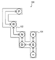
- FIG. 1 is a schematic configuration diagram of a hybrid vehicle 1 including a control device according to the present embodiment.
- the control device according to the present invention is not limited to the hybrid vehicle 1 shown in FIG. 1, but is a hybrid vehicle having a mode different from the hybrid vehicle 1 or an electric vehicle (a vehicle that travels by a driving force generated by a motor using electric power). Etc.) and can be applied to all vehicles not equipped with an automatic transmission.
- Hybrid vehicle 1 includes an engine 120, a first motor generator (hereinafter, “motor generator” is abbreviated as “MG”) 141, and a second MG 142.
- motor generator hereinafter, “MG” is abbreviated as “MG”
- MG 140 the first MG 141 and the second MG 142 are described without being distinguished, they are described as MG 140 for convenience of description.
- the MG 140 functions as a generator or a motor depending on the traveling state of the hybrid vehicle 1.
- the rotation shaft of second MG 142 is connected to drive wheel 180 via reduction gear 160 and drive shaft 170.
- Hybrid vehicle 1 travels by the driving force of at least one of engine 120 and second MG 142.
- second MG 142 functions as a generator, the kinetic energy of the vehicle is converted into electric energy, regenerative braking is performed, and the vehicle is decelerated.
- Hybrid vehicle 1 includes a power split mechanism 200, a battery 150, a converter 152, an inverter 154, a control device 600, and the like.
- the power split mechanism 200 has an input shaft 210 connected to the crankshaft of the engine 120, and distributes the power generated by the engine 120 to two paths of the drive wheel 180 and the first MG 141.
- FIG. 2 shows a schematic configuration diagram of the power split mechanism 200.
- Power split device 200 includes a planetary gear including a sun gear 202, a pinion gear 204, a carrier 206, and a ring gear 208.
- Pinion gear 204 is engaged with sun gear 202 and ring gear 208.
- the carrier 206 supports the pinion gear 204 so that it can rotate.
- Sun gear 202 is connected to the rotation shaft of first MG 141.
- Carrier 206 is connected to the crankshaft of engine 120.
- Ring gear 208 is connected to output shaft 220.
- the engine 120, the first MG 141, and the second MG 142 are connected via the power split mechanism 200 including a planetary gear, so that the rotational speeds of the engine 120, the first MG 141, and the second MG 142 are, for example, as shown in FIG.
- the relationship is a straight line (FIG. 3 is an example during steady operation).
- the battery 150 stores electric power for driving the MG 140.
- the battery 150 typically includes a DC secondary battery such as nickel metal hydride or lithium ion. Note that a large capacity capacitor may be used instead of the battery 150.
- Converter 152 is provided between battery 150 and inverter 154, and performs voltage conversion between battery 150 and inverter 154 based on a control signal from control device 600.
- voltage VH output from converter 152 to inverter 154 is controlled to a value corresponding to the control signal from control device 600.
- Inverter 154 is provided between converter 152 and MG 140, and is supplied to MG 140 by performing power conversion between DC power of converter 152 and AC power of MG 140 based on a control signal from control device 600. Control the current. Thereby, the rotation speed and output torque of MG 140 are controlled to values corresponding to the control signal from control device 600, respectively.
- the control device 600 is an electronic control unit (ECU) including a CPU (Central Processing Unit) (not shown) and a memory.
- ECU electronice control unit
- CPU Central Processing Unit
- the controller 600 is connected to resolver circuits 143 and 144, a shift position sensor 504, an accelerator pedal position sensor 506, an engine speed sensor 510, a vehicle speed sensor 512, and the like via a harness.
- Resolver circuits 143 and 144 detect the rotation speed and rotation direction of first MG 141 and second MG 142.
- the shift position sensor 504 detects the position of the shift lever 502 operated by the driver.
- the accelerator pedal position sensor 506 detects an operation amount (hereinafter referred to as “accelerator operation amount”) A of the accelerator pedal 507 by the driver.
- the accelerator operation amount A is described as a ratio (unit: percent) of the actual operation amount with respect to the entire operation amount of the accelerator pedal 507.
- Engine rotation speed sensor 510 detects engine rotation speed (rotation speed of engine 120) NE.
- the vehicle speed sensor 512 detects the rotational speed of the drive shaft 170 as the vehicle speed V. Each of these sensors outputs a detection result to the control device 600.
- a kick down switch 508 is connected to the control device 600.
- the kick-down switch 508 contacts the accelerator pedal 507 when the accelerator operation amount A reaches a predetermined amount.
- the predetermined amount is described as 80 percent, but the predetermined amount is not limited to 80 percent.
- An elastic body (such as a spring) (not shown) is attached to the kick down switch 508 so that the feeling of accelerator operation after the accelerator pedal 507 contacts the kick down switch 508 becomes heavier than before.
- KD off means a state where the kick down switch 508 is turned off
- KD on means a state where the kick down switch 508 is turned on.
- the control device 600 executes predetermined arithmetic processing based on the signals sent from the above-described sensors, the map and the program stored in the memory, and the hybrid vehicle 1 is in a desired running state. Control equipment. A part of the processing may be executed by hardware (electronic circuit or the like) of the control device 600.
- the movement path of the shift lever 502 will be described with reference to FIG.
- the driver can move the shift lever 502 along the shift gate 100.
- the shift gate 100 includes a main gate 102 and a sub gate 104.
- the main gate 102 is provided with a plurality of shift positions, specifically, a forward position (D position), a neutral position (N position), a parking position (P position), and a reverse position (R position).
- the sub gate 104 is connected to the D position in the main gate 102.
- An S position is provided at the center of the sub-gate 104.
- a (+) position and a ( ⁇ ) position are provided at the upper end and the lower end of the sub-gate 104, respectively.
- the shift position sensor 504 When the driver performs an operation of moving the shift lever 502 from the S position to the (+) position (hereinafter referred to as “(+) operation”), the shift position sensor 504 sends a signal indicating the (+) operation to the control device 600. Send to.
- the shift position sensor 504 when the driver performs an operation of moving the shift lever 502 from the S position to the ( ⁇ ) position (hereinafter referred to as “( ⁇ ) operation”), the shift position sensor 504 outputs a signal indicating the ( ⁇ ) operation. It transmits to the control apparatus 600.
- the driver can change the power transmission state of the power split mechanism 200 by changing the position of the shift lever 502.
- control device 600 controls the hybrid vehicle 1 in the automatic transmission mode.
- control device 600 controls engine 120 and MG 140 such that the ratio of engine rotation speed NE to vehicle speed V changes continuously according to the state of the vehicle.
- control device 600 controls the hybrid vehicle 1 in the manual shift mode.
- control device 600 limits the ratio of engine speed NE to vehicle speed V according to the shift stage selected by the driver (hereinafter referred to as “selected shift stage”).
- selected shift stage the control device 600 sets the lower limit rotational speed NEmin of the engine rotational speed NE based on the vehicle speed V and the selected shift stage, and uses the relationship shown in FIG. 3 described above to set the lower limit of the engine rotational speed NE.
- the value is limited to a value equal to or higher than the rotational speed NEmin. Thereby, a pseudo shift stage can be formed even in the hybrid vehicle 1 in which the stepped automatic transmission is not mounted.
- control device 600 When the control device 600 receives the signal indicating the (+) operation, the control device 600 changes the selected shift stage to a shift stage that is one stage faster than the current shift stage. On the other hand, when receiving the signal indicating the ( ⁇ ) operation, control device 600 changes the selected shift stage to a shift stage that is one stage lower than the current shift stage.
- FIG. 5 shows the relationship between the vehicle speed V, the selected shift stage, and the lower limit rotational speed NEmin.
- the driver can select three shift stages, that is, a low speed shift stage (Lo gear), a medium speed shift stage (Mid gear), and a high speed shift stage (Hi gear) is exemplified.
- the number of shift stages that can be selected by the driver is not limited to three.
- the lower limit rotational speed NEmin is set with the vehicle speed V and the selected shift stage as parameters.
- the engine speed NE is also limited and increased to a value equal to or higher than N3. As a result, it is possible to give the driver a feeling as if the automatic transmission was downshifted according to the driver's shift operation.
- kick down control in this embodiment will be described. If the vehicle is equipped with a stepped automatic transmission, when the kickdown switch 508 is turned on, the automatic transmission is downshifted to generate a larger driving force (to obtain a stronger acceleration force). Is common. However, the hybrid vehicle 1 in this embodiment is not equipped with a stepped automatic transmission.
- the control device 600 limits the driving force when KD is turned off in advance, and releases the restriction when KD is turned on to increase the driving force.
- This series of controls is the kick down control in this embodiment.
- the driver feels as if the automatic transmission has been downshifted (so-called kick-down feeling) when KD is turned on. be able to.
- the amount for limiting the driving force in the kick down control in the manual shift mode is variable for each selected shift stage.
- the control device 600 increases the amount of limiting the driving force as the selected shift stage is the shift stage on the high speed side.
- the higher the shift stage of the selected shift stage the larger the increase in driving force when changing from KD off to KD on, thereby realizing a more natural kick-down feeling according to the selected shift stage. Is possible.
- the most characteristic point of the present embodiment is that the amount for limiting the driving force when KD is off is variable for each selected shift stage.
- FIG. 6 is a functional block diagram of a portion related to driving force control in the manual transmission mode of the control device 600. Note that each functional block shown in FIG. 6 may be realized by providing hardware (such as an electronic circuit) having the function in the control device 600, or software processing corresponding to the function (execution of a program) Etc.) may be realized by causing the control device 600 to perform the above.
- hardware such as an electronic circuit
- software processing corresponding to the function execution of a program
- Control device 600 includes a basic driving force calculation unit 610, a limiting rate calculation unit 620, a required driving force calculation unit 630, a required power calculation unit 640, a lower limit rotation speed calculation unit 650, an engine control unit 660, and an MG control unit 670.
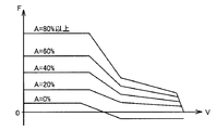
- the basic driving force calculation unit 610 calculates a basic driving force F for driving the hybrid vehicle 1 based on the vehicle speed V and the accelerator operation amount A.
- FIG. 7 shows a correspondence relationship between the vehicle speed V, the accelerator operation amount A, and the basic driving force F.
- the basic driving force F is set to a larger value as the accelerator operation amount A is larger.
- the basic driving force F corresponding to is calculated.
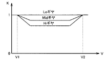
- the limiting rate calculation unit 620 calculates the limiting rate K of the driving force when KD is off based on the vehicle speed V and the selected shift stage. As described above, the selected shift stage is determined by a (+) operation or a ( ⁇ ) operation by the driver.
- FIG. 8 shows the correspondence between the vehicle speed V, the selected shift stage, and the limit rate K.
- the limiting rate K is “1” regardless of the selected shift stage. Is set.
- the limit rate K is set to a smaller value as the selected shift stage is the higher shift stage.
- the limiting rate K remains “1” even if the vehicle speed V is in the range from the predetermined speed V1 to the predetermined speed V2. Is set.
- the required driving force calculation unit 630 receives the basic driving force F from the basic driving force calculation unit 610, the limiting rate K from the limiting rate calculation unit 620, and the kick down signal KD from the kick down switch 508. Based on this, the required driving force Freq is calculated.
- the required driving force calculation unit 630 calculates the product of the basic driving force F and the limiting rate K when KD is off, and sets the result as the required driving force Freq.
- the required driving force calculation unit 630 sets the basic driving force F to the required driving force Freq as it is when KD is on.
- FIG. 9 shows the correspondence relationship between the vehicle speed V, the selected shift stage, and the required driving force Freq separately for when KD is off and when KD is on.
- the required driving force Freq when KD is on is indicated by a broken line
- the required driving force Freq when KD is off is indicated by a solid line. Therefore, the difference between the broken line and the solid line shown in FIG. 9 corresponds to the amount of increase in driving force when the KD is turned off to KD on.
- the required driving force Freq the basic driving force F ⁇ the limiting rate K, and the required driving force Freq is limited by the limiting rate K.
- the limiting rate K is set to a smaller value as the shift stage is on the higher speed side (see FIG. 8 described above). Therefore, the required driving force Freq when KD is off is more limited as the shift stage is higher than the basic driving force F.
- the amount of increase in the driving force when changing from KD off to KD on becomes larger as the selected shift stage is the higher-speed side shift stage. A more natural acceleration feeling can be realized.
- the required power calculation unit 640 calculates the required vehicle power Preq required for the entire hybrid vehicle 1 based on the required driving force Freq from the required driving force calculation unit 630. For example, required power calculation unit 640 calculates charge / discharge required power Pb required by battery 150, and calculates the sum of required drive power Freq and charge / discharge required power Pb as vehicle required power P.
- the lower limit rotational speed calculation unit 650 calculates the lower limit rotational speed NEmin of the engine 120 using the vehicle speed V and the selected shift stage as parameters (see FIG. 5 described above).
- the MG control unit 670 controls the MG 140 so that the actual vehicle driving force becomes the vehicle required power Preq. For example, MG control unit 670 calculates required torque Tm1 of first MG 141 so that engine speed NE becomes required engine speed NEreq in consideration of the relationship shown in FIG. Next, MG control unit 670 calculates a difference between torque obtained by converting requested engine torque TEreq and requested torque Tm1 of first MG 141 into vehicle driving force and requested vehicle power Preq as requested torque Tm2 of second MG 142. Then, MG control unit 670 controls first MG 141 and second MG so that the actual torque of first MG 141 becomes required torque Tm1 and the actual torque of second MG 142 becomes required torque Tm2.
- the actual vehicle driving force becomes a value corresponding to the vehicle required power Preq.
- FIG. 10 is a flowchart showing a processing procedure for realizing the function of the control device 600 described above. The process shown in this flowchart is repeatedly executed at a predetermined cycle time.
- Each step of the flowchart (hereinafter, “step” is abbreviated as “S”) is basically realized by software processing by the control device 600, but hardware processing by an electronic circuit or the like provided in the control device 600. It may be realized by.
- control device 600 calculates basic driving force F based on vehicle speed V and accelerator operation amount A (see FIG. 7 described above).
- control device 600 determines the selected shift stage based on the operation of shift lever 502 by the driver (the above-described (+) operation or (-) operation, etc.).
- control device 600 calculates drive force limiting rate K when KD is off based on vehicle speed V and the selected shift stage. At this time, as shown in FIG. 8 described above, the control device 600 sets the limiting rate K to a smaller value as the selected shift stage is the higher-speed shift stage.
- control device 600 determines whether or not KD is off. If KD is off (YES in S4), the process proceeds to S5. Otherwise (NO in S4), the process proceeds to S6.
- control device 600 sets the product of basic driving force F and limiting rate K to required driving force Freq. That is, the basic driving force F is limited using the limiting rate K.
- control device 600 sets basic driving force F as requested driving force Freq as it is. That is, the basic driving force F is not limited using the limiting rate K. When the basic driving force F is limited until immediately before this processing, the limitation on the basic driving force F is released in this processing.
- control device 600 calculates vehicle required power Preq based on required driving force Freq, and controls engine 120 and MG 140 so that the actual vehicle driving force becomes vehicle required power Preq. To do.
- FIG. 11 shows a driving force timing chart when the kick-down control in this embodiment is executed.
- the driving force indicated by the one-dot chain line indicates the driving force when the selected shift stage is the Lo gear
- the driving force indicated by the solid line indicates the driving force when the selected shift stage is the Mid gear
- the driving force indicated by indicates a driving force when the selected shift stage is a Hi gear.
- the accelerator pedal 507 contacts the kick-down switch 508.
- the accelerator operation amount A increases more than 80%, and the kick down switch 508 is turned on.
- the limit rate K is set to a smaller value as the selected shift stage is higher, so the driving force in the Mid gear is more limited than the driving force in the Lo gear. Furthermore, the driving force in the Hi gear is more limited than the driving force in the Mid gear. Note that the limiting rate at the Lo gear is “1”, and the driving force is not substantially limited.
- the restriction on the driving force using the restriction rate K is released, and the driving force increases if the vehicle is traveling in the Hi gear or the Mid gear.
- the increase amount ⁇ of the driving force in the case of the Hi gear is larger than the increase amount ⁇ of the driving force in the case of the Mid gear because the limit amount when the KD is off is large. Therefore, a natural kick down feeling corresponding to the selected shift stage is realized.
- the basic driving force F is limited in advance using the limiting rate K, and when the KD is on, the restriction is released and the kick-down feeling is realized.
- the amount of limiting the driving force when KD is off the higher the shift stage on the high speed side, the larger the amount of increase in driving force when the shift stage is from KD off to KD on. .
- a more natural acceleration feeling corresponding to the selected shift stage can be realized as compared with the case where the amount of increase in driving force when changing from KD off to KD on is the same regardless of the selected shift stage. Is possible.
- the basic driving force F is limited by the limiting rate K corresponding to the selected shift stage.
- the limitation target is not limited to the basic driving force F.
- the basic driving torque may be calculated based on the vehicle speed V and the accelerator operation amount A, and the basic driving torque may be limited by the limiting rate K corresponding to the selected shift stage.
- the ratio of the engine speed NE to the vehicle speed V is changed according to the selected shift stage using the power split mechanism 200 (see FIG. 5), but the object to be changed according to the selected shift stage is It is not limited to this.
- the target to be changed according to the selected shift stage may be the driving force change rate, the magnitude of the driving force with respect to the accelerator operation amount A, the regenerative braking amount, or the like.
- the present invention can be easily applied to a vehicle that does not have the power split mechanism 200.
Landscapes
- Engineering & Computer Science (AREA)
- Mechanical Engineering (AREA)
- Chemical & Material Sciences (AREA)
- Combustion & Propulsion (AREA)
- Transportation (AREA)
- Power Engineering (AREA)
- Automation & Control Theory (AREA)
- General Engineering & Computer Science (AREA)
- Hybrid Electric Vehicles (AREA)
- Electric Propulsion And Braking For Vehicles (AREA)
- Control Of Transmission Device (AREA)
- Control Of Vehicle Engines Or Engines For Specific Uses (AREA)
Abstract
Description
Claims (7)
- 運転者が複数のシフト段のうちから選択した選択シフト段に応じた走行が可能な車両であって、
前記車両を走行させるための駆動力を発生する駆動装置(120、140)と、
運転者によるアクセル操作量が予め定められた量よりも小さい場合にオフされ、前記アクセル操作量が前記予め定められた量よりも大きい場合にオンされるスイッチ(508)と、
前記スイッチのオフ時に前記駆動力を制限し前記スイッチのオン時に前記駆動力の制限を解除することによって前記スイッチがオフからオンに変化した時に前記駆動力を増加させるように、前記駆動装置を制御する制御装置(600)とを含み、
前記制御装置は、前記選択シフト段に応じて、前記スイッチがオフからオンに変化した時の前記駆動力の増加量を変化させる、車両。 - 前記制御装置は、前記選択シフト段が高速側のシフト段であるほど前記スイッチがオフからオンに変化した時の前記駆動力の増加量を大きい値にする、請求の範囲第1項に記載の車両。
- 前記制御装置は、前記選択シフト段が高速側のシフト段であるほど前記スイッチがオフからオンに変化した時の前記駆動力の増加量を大きい値にするために、前記選択シフト段が高速側のシフト段であるほど前記スイッチのオフ時に前記駆動力を制限する量を大きい値にする、請求の範囲第2項に記載の車両。
- 前記制御装置は、前記選択シフト段が最も低速側のシフト段である場合は、前記スイッチのオフ時であっても前記駆動力を制限しない、請求の範囲第1項に記載の車両。
- 前記駆動装置は、電力を用いて前記駆動力を発生する回転電機(140)を少なくとも含み、
前記車両は、少なくとも前記回転電機が発生する前記駆動力によって走行することが可能な電気車両あるいはハイブリッド車両である、請求の範囲第1項に記載の車両。 - 運転者が複数のシフト段のうちから選択した選択シフト段に応じた走行が可能な車両であって、
前記車両を走行させるための駆動力を発生する駆動装置(120、140)と、
運転者によるアクセル操作量が予め定められた量よりも小さい場合にオフされ、前記アクセル操作量が前記予め定められた量よりも大きい場合にオンされるスイッチ(508)と、
前記スイッチのオフ時に前記選択シフト段に応じて前記駆動力を制限し前記スイッチのオン時に前記駆動力の制限を解除することによって前記スイッチがオフからオンに変化した時に前記駆動力を増加させるように、前記駆動装置を制御する制御装置(600)とを含み、
前記制御装置は、
前記アクセル操作量に応じた基本駆動力を制限するために用いられる制限率を前記選択シフト段に応じて算出する算出部(620)と、
前記スイッチのオフ時に前記制限率を用いて前記基本駆動力を制限し、前記スイッチのオン時に前記制限率を用いた前記基本駆動力の制限を解除することによって前記スイッチがオフからオンに変化した時に前記駆動力を増加させるように、前記駆動装置を制御する制御部(630、640、650、660、670)とを含み、
前記算出部は、前記選択シフト段が最も低速側のシフト段である場合、前記基本駆動力を実質的に制限しないように前記制限率を算出し、前記選択シフト段が最も低速側のシフト段でない場合、前記選択シフト段が高速側のシフト段であるほど前記基本駆動力を制限する量がより大きくなるように前記制限率を算出する、車両。 - 運転者が複数のシフト段のうちから選択した選択シフト段に応じた走行が可能な車両の制御装置(600)が行なう制御方法であって、前記車両は、前記車両を走行させるための駆動力を発生する駆動装置(120、140)と、運転者によるアクセル操作量が予め定められた量よりも小さい場合にオフされ、前記アクセル操作量が前記予め定められた量よりも大きい場合にオンされるスイッチ(508)とを備え、
前記制御方法は、
前記選択シフト段を判断するステップと、
前記スイッチのオフ時に前記駆動力を制限し前記スイッチのオン時に前記駆動力の制限を解除することによって前記スイッチがオフからオンに変化した時に前記駆動力を増加させるように、前記駆動装置を制御するステップとを含み、
前記駆動装置を制御するステップは、前記選択シフト段に応じて、前記スイッチがオフからオンに変化した時の前記駆動力の増加量を変化させるステップを含む、車両の制御方法。
Priority Applications (5)
| Application Number | Priority Date | Filing Date | Title |
|---|---|---|---|
| PCT/JP2010/051011 WO2011092806A1 (ja) | 2010-01-27 | 2010-01-27 | 車両およびその制御方法 |
| EP10844572.7A EP2529989B1 (en) | 2010-01-27 | 2010-01-27 | Vehicle and control method thereof |
| CN201080056320.9A CN102656073B (zh) | 2010-01-27 | 2010-01-27 | 车辆及其控制方法 |
| US13/575,438 US8768848B2 (en) | 2010-01-27 | 2010-01-27 | Vehicle and method of controlling the same |
| JP2011551614A JP5338923B2 (ja) | 2010-01-27 | 2010-01-27 | 車両およびその制御方法 |
Applications Claiming Priority (1)
| Application Number | Priority Date | Filing Date | Title |
|---|---|---|---|
| PCT/JP2010/051011 WO2011092806A1 (ja) | 2010-01-27 | 2010-01-27 | 車両およびその制御方法 |
Publications (1)
| Publication Number | Publication Date |
|---|---|
| WO2011092806A1 true WO2011092806A1 (ja) | 2011-08-04 |
Family
ID=44318819
Family Applications (1)
| Application Number | Title | Priority Date | Filing Date |
|---|---|---|---|
| PCT/JP2010/051011 Ceased WO2011092806A1 (ja) | 2010-01-27 | 2010-01-27 | 車両およびその制御方法 |
Country Status (5)
| Country | Link |
|---|---|
| US (1) | US8768848B2 (ja) |
| EP (1) | EP2529989B1 (ja) |
| JP (1) | JP5338923B2 (ja) |
| CN (1) | CN102656073B (ja) |
| WO (1) | WO2011092806A1 (ja) |
Cited By (3)
| Publication number | Priority date | Publication date | Assignee | Title |
|---|---|---|---|---|
| JP2013130225A (ja) * | 2011-12-21 | 2013-07-04 | Toyota Motor Corp | ハイブリッド車両の変速指示装置 |
| CN111556834A (zh) * | 2017-11-14 | 2020-08-18 | 卡明斯公司 | 用户选择的用于动力传动系统管理的控制特征 |
| JP2022030834A (ja) * | 2020-08-07 | 2022-02-18 | トヨタ自動車株式会社 | 電気自動車 |
Families Citing this family (2)
| Publication number | Priority date | Publication date | Assignee | Title |
|---|---|---|---|---|
| KR101428250B1 (ko) * | 2012-12-06 | 2014-08-07 | 현대자동차주식회사 | 차량용 가속페달의 킥 다운 제어장치 및 방법 |
| US10699268B2 (en) * | 2015-12-30 | 2020-06-30 | Thales Dis France Sa | Method, server and system for authorizing a transaction |
Citations (2)
| Publication number | Priority date | Publication date | Assignee | Title |
|---|---|---|---|---|
| JP2007055535A (ja) * | 2005-08-26 | 2007-03-08 | Toyota Motor Corp | 自動車およびその制御方法 |
| JP2007239504A (ja) | 2006-03-06 | 2007-09-20 | Toyota Motor Corp | 自動車およびその制御方法 |
Family Cites Families (14)
| Publication number | Priority date | Publication date | Assignee | Title |
|---|---|---|---|---|
| JP2000175305A (ja) | 1998-12-03 | 2000-06-23 | Toyota Motor Corp | ハイブリッド車 |
| US6503170B1 (en) * | 1999-08-20 | 2003-01-07 | Toyota Jidosha Kabushiki Kaisha | Control device for an automatic transmission |
| JP3600518B2 (ja) * | 2000-10-11 | 2004-12-15 | トヨタ自動車株式会社 | 車両用変速制御装置 |
| JP2004090886A (ja) * | 2002-09-04 | 2004-03-25 | Advics:Kk | 車両のトラクション制御装置 |
| DE10351656A1 (de) * | 2003-11-05 | 2005-06-02 | Daimlerchrysler Ag | Kraftfahrzeug mit Kraftmaschine und Beschleunigungspedal |
| JP4857518B2 (ja) * | 2003-12-24 | 2012-01-18 | トヨタ自動車株式会社 | 車両の制御装置 |
| JP4055781B2 (ja) | 2004-05-06 | 2008-03-05 | トヨタ自動車株式会社 | ハイブリッド車およびその制御方法 |
| JP4584856B2 (ja) * | 2006-03-29 | 2010-11-24 | ジヤトコ株式会社 | 自動変速機の変速制御装置 |
| JP4165596B2 (ja) * | 2006-10-18 | 2008-10-15 | トヨタ自動車株式会社 | 制駆動力制御装置 |
| JP5018356B2 (ja) * | 2006-11-22 | 2012-09-05 | 日産自動車株式会社 | 自動変速機の変速制御装置 |
| US7757800B2 (en) * | 2006-12-12 | 2010-07-20 | Grigoriy Epshteyn | Monocylindrical hybrid powertrain and method of operation |
| JP4293249B2 (ja) | 2007-03-06 | 2009-07-08 | トヨタ自動車株式会社 | 車両およびその制御方法 |
| CN101349345A (zh) * | 2007-07-20 | 2009-01-21 | 奇瑞汽车股份有限公司 | 一种无级变速器的换挡控制方法及装置 |
| JP4960799B2 (ja) * | 2007-08-06 | 2012-06-27 | 本田技研工業株式会社 | ハイブリッド車両の制御装置 |
-
2010
- 2010-01-27 EP EP10844572.7A patent/EP2529989B1/en not_active Not-in-force
- 2010-01-27 JP JP2011551614A patent/JP5338923B2/ja active Active
- 2010-01-27 US US13/575,438 patent/US8768848B2/en active Active
- 2010-01-27 CN CN201080056320.9A patent/CN102656073B/zh not_active Expired - Fee Related
- 2010-01-27 WO PCT/JP2010/051011 patent/WO2011092806A1/ja not_active Ceased
Patent Citations (2)
| Publication number | Priority date | Publication date | Assignee | Title |
|---|---|---|---|---|
| JP2007055535A (ja) * | 2005-08-26 | 2007-03-08 | Toyota Motor Corp | 自動車およびその制御方法 |
| JP2007239504A (ja) | 2006-03-06 | 2007-09-20 | Toyota Motor Corp | 自動車およびその制御方法 |
Non-Patent Citations (1)
| Title |
|---|
| See also references of EP2529989A4 |
Cited By (5)
| Publication number | Priority date | Publication date | Assignee | Title |
|---|---|---|---|---|
| JP2013130225A (ja) * | 2011-12-21 | 2013-07-04 | Toyota Motor Corp | ハイブリッド車両の変速指示装置 |
| CN111556834A (zh) * | 2017-11-14 | 2020-08-18 | 卡明斯公司 | 用户选择的用于动力传动系统管理的控制特征 |
| CN111556834B (zh) * | 2017-11-14 | 2024-01-30 | 卡明斯公司 | 用户选择的用于动力传动系统管理的控制特征 |
| JP2022030834A (ja) * | 2020-08-07 | 2022-02-18 | トヨタ自動車株式会社 | 電気自動車 |
| JP7298565B2 (ja) | 2020-08-07 | 2023-06-27 | トヨタ自動車株式会社 | 電気自動車 |
Also Published As
| Publication number | Publication date |
|---|---|
| US20120303228A1 (en) | 2012-11-29 |
| JPWO2011092806A1 (ja) | 2013-05-30 |
| EP2529989B1 (en) | 2016-09-21 |
| JP5338923B2 (ja) | 2013-11-13 |
| US8768848B2 (en) | 2014-07-01 |
| EP2529989A1 (en) | 2012-12-05 |
| CN102656073A (zh) | 2012-09-05 |
| CN102656073B (zh) | 2014-08-06 |
| EP2529989A4 (en) | 2014-12-24 |
Similar Documents
| Publication | Publication Date | Title |
|---|---|---|
| CN103596827B (zh) | 车辆的控制装置 | |
| JP6627788B2 (ja) | ハイブリッド車両 | |
| US7957856B2 (en) | Control device and control method of hybrid vehicle | |
| JP6083438B2 (ja) | ハイブリッド車両の走行制御装置 | |
| CN112440967B (zh) | 混合动力车辆 | |
| CN103895519A (zh) | 再生制动控制装置 | |
| JP6149772B2 (ja) | ハイブリッド車両 | |
| JP2018191366A (ja) | 車両 | |
| JP5338923B2 (ja) | 車両およびその制御方法 | |
| JP4114643B2 (ja) | 車両用駆動装置の制御装置 | |
| JP5854055B2 (ja) | 変速指示装置 | |
| CN112519751B (zh) | 混合动力车辆 | |
| CN105564433B (zh) | 混合动力车及其控制方法 | |
| JP5917866B2 (ja) | 車両の制御装置 | |
| JP5359937B2 (ja) | ハイブリッド車両 | |
| JP2016124523A (ja) | ハイブリッド自動車 | |
| KR20130055082A (ko) | 하이브리드 차량의 경사로 밀림 방지 제어 방법 | |
| JP5987323B2 (ja) | 車両の制御装置 | |
| JP2006275175A (ja) | ハイブリッド車の制御装置 | |
| JP2010241307A (ja) | ハイブリッド自動車および車載用変速機の変速時の制御方法 | |
| JP5786749B2 (ja) | 変速指示装置 | |
| JP2000278816A (ja) | 電気自動車の変速制御装置 | |
| KR20240147796A (ko) | 전기차의 가상 변속 시스템을 활용한 엔진 브레이크 구현 방법 | |
| JP2018007372A (ja) | 自動車 | |
| JP2016132418A (ja) | 車両の制御装置 |
Legal Events
| Date | Code | Title | Description |
|---|---|---|---|
| WWE | Wipo information: entry into national phase |
Ref document number: 201080056320.9 Country of ref document: CN |
|
| 121 | Ep: the epo has been informed by wipo that ep was designated in this application |
Ref document number: 10844572 Country of ref document: EP Kind code of ref document: A1 |
|
| WWE | Wipo information: entry into national phase |
Ref document number: 2011551614 Country of ref document: JP |
|
| REEP | Request for entry into the european phase |
Ref document number: 2010844572 Country of ref document: EP |
|
| WWE | Wipo information: entry into national phase |
Ref document number: 2010844572 Country of ref document: EP |
|
| WWE | Wipo information: entry into national phase |
Ref document number: 13575438 Country of ref document: US |
|
| NENP | Non-entry into the national phase |
Ref country code: DE |