WO2011092923A1 - エアバッグ - Google Patents
エアバッグ Download PDFInfo
- Publication number
- WO2011092923A1 WO2011092923A1 PCT/JP2010/070109 JP2010070109W WO2011092923A1 WO 2011092923 A1 WO2011092923 A1 WO 2011092923A1 JP 2010070109 W JP2010070109 W JP 2010070109W WO 2011092923 A1 WO2011092923 A1 WO 2011092923A1
- Authority
- WO
- WIPO (PCT)
- Prior art keywords
- airbag
- portions
- joined
- sheet
- joining
- Prior art date
- Legal status (The legal status is an assumption and is not a legal conclusion. Google has not performed a legal analysis and makes no representation as to the accuracy of the status listed.)
- Ceased
Links
Images



Classifications
-
- B—PERFORMING OPERATIONS; TRANSPORTING
- B60—VEHICLES IN GENERAL
- B60R—VEHICLES, VEHICLE FITTINGS, OR VEHICLE PARTS, NOT OTHERWISE PROVIDED FOR
- B60R21/00—Arrangements or fittings on vehicles for protecting or preventing injuries to occupants or pedestrians in case of accidents or other traffic risks
- B60R21/02—Occupant safety arrangements or fittings, e.g. crash pads
- B60R21/16—Inflatable occupant restraints or confinements designed to inflate upon impact or impending impact, e.g. air bags
- B60R21/23—Inflatable members
- B60R21/239—Inflatable members characterised by their venting means
-
- B—PERFORMING OPERATIONS; TRANSPORTING
- B60—VEHICLES IN GENERAL
- B60R—VEHICLES, VEHICLE FITTINGS, OR VEHICLE PARTS, NOT OTHERWISE PROVIDED FOR
- B60R21/00—Arrangements or fittings on vehicles for protecting or preventing injuries to occupants or pedestrians in case of accidents or other traffic risks
- B60R21/02—Occupant safety arrangements or fittings, e.g. crash pads
- B60R21/16—Inflatable occupant restraints or confinements designed to inflate upon impact or impending impact, e.g. air bags
- B60R21/23—Inflatable members
- B60R21/235—Inflatable members characterised by their material
- B60R2021/23571—Inflatable members characterised by their material characterised by connections between panels
-
- B—PERFORMING OPERATIONS; TRANSPORTING
- B60—VEHICLES IN GENERAL
- B60R—VEHICLES, VEHICLE FITTINGS, OR VEHICLE PARTS, NOT OTHERWISE PROVIDED FOR
- B60R21/00—Arrangements or fittings on vehicles for protecting or preventing injuries to occupants or pedestrians in case of accidents or other traffic risks
- B60R21/02—Occupant safety arrangements or fittings, e.g. crash pads
- B60R21/16—Inflatable occupant restraints or confinements designed to inflate upon impact or impending impact, e.g. air bags
- B60R21/20—Arrangements for storing inflatable members in their non-use or deflated condition; Arrangement or mounting of air bag modules or components
- B60R21/203—Arrangements for storing inflatable members in their non-use or deflated condition; Arrangement or mounting of air bag modules or components in steering wheels or steering columns
Definitions
- the present invention relates to an airbag that is deployed by gas generated by an inflator, and more particularly to a vehicle airbag.
- a vehicle airbag protects an occupant by deploying in front of an occupant seated in a driver seat or a passenger seat when collision energy acts on the vehicle.
- Such an air bag has a vent hole.
- the vent hole is a vent hole for releasing a part of gas to the outside so as to restrict an excessive increase in internal pressure when the airbag is deployed.
- the size of the vent hole does not change while being set in advance. For this reason, it is not possible to finely control the release rate and the release amount of the gas released from the vent hole to the occupant's collision with the deployed airbag.
- the gas in the airbag starts to be released to the outside through the vent hole from the initial stage where the airbag starts to be deployed in front of the passenger.
- the internal pressure of the airbag can be maintained for a long time.
- the airbag known from Patent Document 1 has a vent hole cover for closing the vent hole.
- the vent hole cover is sewn to the airbag by a plurality of sewing portions.
- the plurality of sewn portions are sequentially broken as the internal pressure increases when the airbag is deployed, and the breaking is completed at the end of deployment of the airbag.
- the vent hole cover is removed from the vent hole, so that the vent hole is opened. That is, it is possible to control the timing at which the gas in the airbag is released from the vent hole to the outside.
- An object of the present invention is to provide a technique capable of finely controlling the discharge timing, discharge speed, and discharge amount of gas discharged from the airbag to the outside.
- the second sheet is constituted by a plurality of base fabrics, and the plurality of base fabrics are arranged along a circumferential direction, and overlapping portions where adjacent ends overlap each other. And at least a part of each of the overlapping portions has a non-joined portion that is not joined to each other, and when the airbag is deployed and the protection object collides, the non-joined portion An air bag is provided that allows gas to pass through.
- the second sheet has a circular shape as a whole, and each of the plurality of base fabrics is formed in a fan shape based on the center of the circle.
- the non-joining portion extends in the radial direction with the circular center as a reference.
- At least one of the number of the non-joined portions, the overlap margin of the overlapping portions in the non-joined portions, and the length of the non-joined portions is an expanded state. It is set so that the non-joined portion starts to open from the stage when the protection object collides with the airbag.
- the airbag according to claim 2 is housed in a hub of a steering wheel for a vehicle, and the non-joining portion is configured such that the airbag deployed in a passenger compartment is mounted on a vehicle.
- the vehicle steering wheel is positioned so that at least part of the spoke does not overlap.
- the non-joining portions there are a plurality of the non-joining portions, and the plurality of non-joining portions are equally positioned in the circumferential direction with respect to the center of the circle.
- the plurality of base fabrics are arranged along the circumferential direction, and adjacent ends overlap each other to form an overlapping portion. At least a part of each overlapping portion is formed of a plurality of non-joined portions that are not joined to each other. This non-joined portion can be set so as not to be opened by the internal pressure when the airbag is completely deployed. For this reason, the airbag can substantially maintain the deployed shape.
- the airbag is deformed, so that the non-joined part is opened and excess gas in the airbag is released to the outside. Is possible. For this reason, it is possible to finely set (control) the discharge timing, discharge speed, and discharge amount of the gas released from the non-joined portion in accordance with the collision type of the object to be protected against the deployed airbag. . Moreover, in order to set the discharge timing, the discharge speed, and the discharge amount by the airbag, it is possible to simply configure at least a part of the overlapping portions of the plurality of base fabrics.
- the collision mode for example, there are a first collision mode in which the protection target object collides with the outer peripheral portion of the deployed airbag and a second collision mode in which the protection target object collides with the front surface of the deployed airbag. is there.
- the plurality of non-joined portions extend in the radial direction with reference to the center of the circular second sheet.
- the shape of the airbag changes when the object to be protected collides. With this shape change, the plurality of base fabrics are pulled in the circumferential direction with the center as a reference along the surface of the second sheet. Since the non-joined portion extends in the radial direction with respect to the center, the non-joined portion can be started to be opened in a timely and reliable manner by effectively utilizing the pulling action in the circumferential direction with respect to the center. .
- At least any one value of the number of non-joining parts, the overlap margin of the non-joining part, and the length of the non-joining part is set in advance, Then, it starts to open from the stage when the protection object collides with the airbag in the deployed state. In this way, it is possible to finely set the discharge timing, discharge speed, and discharge amount of the gas released from the non-joined portion to the outside in accordance with the form of collision of the object to be protected against the deployed airbag.
- the non-joining portion is positioned so that at least a portion thereof does not overlap with the spokes of the steering wheel when the airbag deployed in the passenger compartment is viewed from the front side of the vehicle. .
- emitted gas can flow into a vehicle interior, without being interrupted by a spoke. Therefore, the excess gas in the airbag can be discharged to the outside quickly and reliably.
- the invention according to claim 5 there are a plurality of non-joining portions.
- the plurality of non-joined portions are equally positioned in the circumferential direction with reference to the center of the circular back portion. For this reason, regardless of the steering state of the steering wheel, the positional relationship of the plurality of non-joined portions with respect to the steering wheel is not changed and is evenly positioned in the circumferential direction with respect to the steering wheel. Therefore, the shape of the airbag is likely to collapse locally (easily deformed) regardless of which part of the deployed airbag collides with the object to be protected. As a result, a part of the non-joined portion is easily opened locally, so that it is easy to start gas emission.
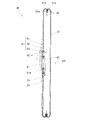
- FIG. 3 is a cross-sectional view taken along line 3-3 in FIG.
- FIG. 4 is an exploded view of the airbag shown in FIG. 3.
- It is a block diagram of the 2nd non-joining part shown by FIG.
- FIG. 3 is an operation diagram of the airbag shown in FIG. 2.
- It is the figure which looked at the structure which extended the airbag by Example 2 of this invention from the front side of the vehicle.
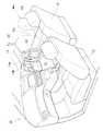
- the vehicle 10 is equipped with an airbag device 20.
- the airbag device 20 deploys the airbag 30 in the vehicle compartment 11 by the high-pressure gas generated by the inflator 21 (see FIGS. 3 and 4) when collision energy acts on the vehicle 10.
- the airbag 30 is protected by being deployed on the front side of an occupant Mn seated in various seats such as the driver's seat 12, the passenger seat 13, and a rear seat (not shown) and restraining the occupant Mn.
- the airbag device 20 a device for protecting an occupant Mn (driver Mn) sitting on the driver's seat 12 will be described.
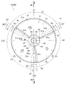
- FIG. 2 shows the airbag 30 as viewed from the front side of the vehicle 10.
- the airbag device 20 includes an inflator 21 indicated by an imaginary line, a retainer 22, a fixing ring 23, and an airbag 30.
- the inflator 21 ignites a gas generating agent when an ignition signal is received from a control unit (not shown) due to the collision energy acting on the vehicle 10, thereby causing a high-pressure gas for airbag deployment (hereinafter simply “ Gas ”) and is supplied to the airbag 30.
- the inflator 21 has a mounting flange 21a.
- the retainer 22 is a member that holds the airbag 30 in a folded state and supports the inflator 21, and is provided on the steering wheel 14 (FIG. 1). By bolting the mounting flange 21a to the retainer 22, the inflator 21 is fixed to the hub 14a of the steering wheel 14 shown in FIG. As a result, the airbag 30 is accommodated in the hub 14a of the steering wheel 14.
- the airbag 30 includes a rear seat (first seat) 31 and a front seat 41 (second seat or rear portion) 41.
- the overall shape of the rear sheet 31 and the front sheet 41 is circular.
- the circular airbag 30 is configured by superimposing the rear seat 31 and the front seat 41 on each other and joining the outer peripheral portions 31a and 41a together (sewing integrally with the outer peripheral stitching portion 42). .
- the rear seat 31 is a front portion (the latter half of the bag) facing the occupant Mn that is a protection target when the airbag 30 is deployed in the vehicle compartment 11. Yes, it is composed of a single base fabric.
- the front seat 41 faces the rear portion (the front half of the bag) that does not contact the occupant Mn, that is, the steering wheel 14. This is the part that is located.
- the front sheet 41 is appropriately referred to as a “rear portion 41”.
- the inflator insertion hole 43 is a circular through hole that is disposed at the center CP (the center CP of the airbag 30, the circular center CP) of the front seat 41 and surrounds the inserted inflator 21.
- the gas generated by the inflator 21 is supplied into the airbag 30.
- the plurality of bolt holes 44 are arranged around the inflator insertion hole 43.
- the airbag 30 is attached to the retainer 22 by superimposing the front seat 41 and the fixing ring 23 on the mounting flange 21a of the inflator 21 and screwing the bolt 24 (see FIG. 4) inserted into the bolt hole 44 into the mounting flange 21a. It is attached.
- the front sheet 41 (rear portion 41) is a composite body integrally formed by a plurality of divided base fabrics 51 to 53.
- the front sheet 41 is composed of three base fabrics 51 to 53.
- the plurality of base fabrics 51 to 53 are evenly arranged along the sheet surface (rear surface) of the front sheet 41, and only circumferential ends (boundaries) 51a, 52a, 53a adjacent to each other are They are overlapping.
- the overlapping portions 61 to 63 are hereinafter referred to as “overlapping portions 61 to 63”. Each of the overlapping portions 61 to 63 is equally positioned in the circumferential direction with respect to the circular center CP.
- the azimuth corresponding to 12:00 of the timepiece is set to 0 ° with respect to the circular center CP. Assume that the angle increases clockwise with respect to 0 °.
- the plurality of base fabrics 51 to 53 are appropriately referred to as “first base fabric 51”, “second base fabric 52”, and “third base fabric 53”.
- the first base fabric 51 is positioned at an azimuth of 0 °, and is positioned in the order of the second base fabric 52 and the third base fabric 53 in the clockwise direction.
- the first overlapping portion 61 is a portion where the end 51a of the first base fabric 51 and the end 52a of the second base fabric 52 overlap each other.
- the second overlapping portion 62 is a portion where the end 52a of the second base fabric 52 and the end 53a of the third base fabric 53 overlap each other.
- the third overlapping portion 63 is a portion where the end 53a of the third base fabric 53 and the end 51a of the first base fabric 51 overlap each other.
- each of the plurality of base fabrics 51 to 53 is formed in a fan shape based on a circular center CP so that the entire shape of the front sheet 41 is circular.
- the sector-shaped central angle ⁇ 1 is equal or almost equal.
- the overlap angle ⁇ 2 (overlap allowance) of each of the overlapping portions 61 to 63 where the plurality of base fabrics 51 to 53 are adjacent to each other is equal or almost equal.
- the overlap angle ⁇ 2 is set to an optimum value in consideration of the discharge start pressure, discharge speed, and discharge amount of the gas released from the airbag 30 to the outside.
- the first overlapping portion 61 is located at the azimuth 60 °
- the second overlapping portion 62 is located at the azimuth 180 °
- the third overlapping portion 63 is located at the azimuth 300 °.
- the overlapping margin of the overlapping portions 61 to 63 is not limited to the overlapping angle ⁇ 2, and may be, for example, a constant width.
- the base fabric and the plurality of base fabrics 51 to 53 constituting the rear sheet 31 are all made of the same material and the same thickness, that is, a flexible panel.
- This cloth has different friction characteristics (friction resistance) on the front and back. For example, the friction characteristics are different between the front and back surfaces by applying a silicon coating only to one side of the cloth.
- the rear sheet 31 and the plurality of base fabrics 51 to 53 face each other with low frictional resistance.
- Each of the base fabrics 51 to 53 includes a central circular base portion 54 with respect to the center CP, and a fan portion 55 connected to the outer periphery of the base portion 54.
- the inflator insertion hole 43 and the bolt hole 44 are formed in the center of the base 54.
- the base portions 54 of the respective base fabrics 51 to 53 are all overlapped and joined to each other (sewn together at the stitching portion 45). For this reason, the strength of the portion of the inflator insertion hole 43 in the front seat 41 is increased.
- the fan part 55 has an arcuate folded part 55a and linear folded parts 55b, 55b.
- the arcuate folded portion 55a is an arcuate folded portion that is edged by folding the arcuate edge of the fan toward the rear sheet 31 side.
- the arcuate folded portion 55a forms the outer peripheral portion 41a of the front sheet 41 shown in FIG.
- the straight folded portions 55b and 55b have their edges at the ends in the circumferential direction of the fan (corresponding to the circumferential ends 51a, 52a and 53a of the plurality of base fabrics 51 to 53) folded back toward the rear sheet 31. This is a substantially linear folded portion bordered by.
- the straight folded portions 55b and 55b are sewn so as to maintain an edged state.
- FIG. 5A shows an enlarged view of the second non-joining portion 62a shown in FIG.
- FIG. 5B is an enlarged cross-sectional view taken along line bb in FIG.
- FIGS. 2 and 5 (a) and 5 (b) at least a part of each of the overlapping portions 61 to 63 is not joined to each other (not sewn together by the stitching portion 65).
- Non-joined portions 61a to 63a are formed.
- the non-bonded portions 61a to 63a are referred to as “first non-bonded portion 61a”, “second non-bonded portion 62a”, and “third non-bonded portion 63a”, respectively.
- non-joined portions 61a to 63a are used in place of known vent holes.
- the non-joining portions 61a to 63a are closed in a normal state where there is no or low internal pressure of the airbag 30, and when the internal pressure of the airbag 30 reaches a predetermined value, the non-bonded portions 61a to 63a are opened as the internal pressure increases. Can be released.
- the length Ln of the non-joint portions 61a to 63a is set so that the total length Ls of the circumferential ends 51a, 52a, 53a of the fan portion 55 is the maximum value, and the discharge start pressure and discharge speed of the gas released from the airbag 30 to the outside And is set to an optimum value in consideration of the discharge amount.
- the plurality of non-joined portions 61a to 63a are equally positioned in the circumferential direction with respect to the circular center CP, and extend radially from the center CP.
- the spoke 14b of the steering wheel 14 is located only in the lower half of the steering wheel 14 in a neutral state of steering. That is, the spoke 14b is generally located in the range of the azimuth 90 ° to 270 °.
- the first overlapping portion 61 and the first non-joining portion 61a are positioned in the azimuth 60 °
- the third overlapping portion 63 and the third non-joining portion 63a are in the azimuth 300 °. Is located.
- the plurality of non-joined portions 61a to 63a are positioned so that at least a part thereof does not overlap with the spoke 14b of the steering wheel 14 when the airbag 30 deployed in the vehicle interior 11 is viewed from the back. ing.
- the inflator 21 shown in FIG. 3 receives an ignition signal and ignites the gas generating agent, thereby generating gas and Supply.
- the airbag 30 housed in a folded state on the steering wheel 14 (see FIG. 1) starts to be deployed by the supplied gas.
- a cover (not shown) attached to the steering wheel 14 is broken from the tear line to form an opening for the airbag 30 to pop out. As a result, the airbag 30 starts to be deployed in the vehicle compartment 11.
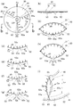
- FIG. 7A schematically shows the airbag 30 viewed from the front side of the vehicle 10, and corresponds to FIG. FIG. 7B shows a cross section of FIG. 7A taken along line bb.
- FIG. 7C schematically shows the airbag 30 at the completion of deployment, and corresponds to FIG.
- FIG. 7D shows an enlarged view of the second non-joined portion 62a shown in FIG.
- FIGS. 7 (e) to 7 (g) show a state in which the second non-joined portion 62a shown in FIG. 7 (d) changes according to the increase in the internal pressure pb.
- FIG. 7 (h) schematically shows the airbag 30 in the state of FIG. 7 (g).
- FIG. 7 (i) is an enlarged view showing that the second non-joined portion 62a is open in the state of FIG. 7 (h).
- the internal pressure pb increases, the plurality of base fabrics 51 to 53 are pulled along the surface of the front sheet 41 in the circumferential direction (arrow Te and Te directions) with the circular center CP as a reference.
- the internal pressure pb of the airbag 30 at the stage of completion of the deployment is relatively small. Since the pressure difference between the inside and outside of the airbag 30 is small, the non-joined portions 61a to 63a are closed as shown in FIGS. 7 (c) and 7 (d). For this reason, the amount of leakage of the gas Ga in the airbag 30 from the non-joint portions 61a to 63a to the outside is small. That is, the internal pressure pb does not reach a predetermined reference pressure that is set in advance. For this reason, the airbag 30 substantially maintains the deployed shape.
- the occupant Mn shown in FIG. 1 collides with the airbag 30 (secondary collision).
- the shape of the airbag 30 changes when the occupant Mn collides.
- the internal pressure pb of the airbag 30 further increases.
- the plurality of base fabrics 51 to 53 are further pulled along the surface of the front sheet 41 in the circumferential direction with the circular center CP as a reference.
- the plurality of base fabrics 51 to 53 are further pulled along the surface of the front sheet 41 in the circumferential direction with the circular center CP as a reference.
- the overlapping portions 61 to 63a in the non-joint portions 61a to 63a are caused by a pulling action in the circumferential direction with the center CP as a reference.
- the overlap allowance ⁇ 2 of 63 rapidly decreases. That is, the overlap allowance ⁇ 2 changes so as to decrease in the order shown in FIGS. Thereafter, as shown in FIGS. 7G and 7H, the non-bonded portions 61a to 63a are completely opened.
- the non-joined portions 61a to 63a substantially start to open from the stage where the deployed airbag 30 collides with the occupant Mn (protected object Mn). That is, the non-bonded portions 61a to 63a open in the order of FIG. 7 (f) and FIG. 7 (g), and discharge excess gas Ga in the airbag 30 to the outside.
- FIGS. 7 (h) and 7 (i) show a state in which a large amount of excess gas Ga in the airbag 30 is released due to the large opening of the non-joined portions 61a to 63a.
- Excessive gas Ga is discharged from the non-bonded portions 61a to 63a to the outside, so that an excessive increase in the internal pressure pb of the airbag 30 is prevented. As a result, the collision energy when the occupant Mn collides with the airbag 30 can be sufficiently mitigated.
- the plurality of non-joining portions 61a to 63a extend radially with the circular center CP as a reference, the pulling action in the circumferential direction with the circular center CP as a reference is effectively used to make the non-joining.
- the parts 61a to 63a can be started to open with good timing.
- the release timing, release speed, and release amount can be set finely. For example, the case of the 1st collision form and the 2nd collision form can be considered.
- the first collision mode is a mode in which the head Hd of the occupant Mn collides with the upper end portion (outer peripheral portion) of the airbag 30 that is deployed as shown in FIG.
- this form is centered from the outside of the outer periphery of the airbag 30 when viewed from the occupant Mn side when the airbag 30 is deployed in the passenger compartment 11.
- This is a form in which the head Hd collides in the so-called radial direction toward the arrow (in the direction of the arrow Fs).
- the shape of the airbag 30 is likely to collapse locally (easily deformed) by the collision energy (secondary collision energy) when the head Hd collides with the airbag 30.
- the force with which the base fabrics 51 to 53 are pulled in the directions of the arrows Te and Te increases.
- part of the non-joint portions 61a to 63a is likely to be locally opened, and the amount of gas Ga released from the non-joint portions 61a to 63a to the outside increases.
- the large secondary collision energy given to the occupant Mn can be sufficiently relaxed.
- the second collision mode is a mode in which the chest Ch of the occupant Mn collides with the front surface of the deployed airbag 30 as shown in FIG.
- the shape of the airbag 30 is relatively easily maintained even when the secondary collision energy acts.
- the non-joint portions 61a to 63a are difficult to open, and the amount of gas Ga released from the non-joint portions 61a to 63a to the outside is reduced. By reducing the discharge amount, large secondary collision energy can be sufficiently absorbed by the entire airbag 30.
- At least one of the number of the non-joint portions 61a to 63a, the overlap margin ⁇ 2 of the overlap portions 61 to 63 in the non-joint portions 61a to 63a, and the length Ln of the non-joint portions 61a to 63a is:
- the non-joint portions 61a to 63a are set to start to open in accordance with the increase in the internal pressure pb of the airbag 30 from the stage when the airbag 30 is inflated and starts to contact the occupant Mn (protection target Mn).
- the plurality of base fabrics 51 to 53 for constituting the back surface of the airbag 30 are arranged along the back surface and the ends 51a and 52a adjacent to each other. , 53a overlap each other to form overlapping portions 61-63. At least a part of each of the overlapping portions 61 to 63 is configured as non-joined portions 61a to 63a that are not joined to each other.
- the discharge timing, discharge speed, and discharge amount of the gas Ga discharged from the non-joint portions 61a to 63a to the outside can be finely controlled in accordance with the collision mode of the occupant Mn against the deployed airbag 30.
- the overlap allowance ⁇ 2 and the length Ln of the non-joint portions 61a to 63a may be set to different values for each non-joint portion 61a, 62a, 63a.
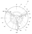
- FIG. 8 shows a configuration in which the airbag 30A of the second embodiment is viewed from the front side of the vehicle 10 (FIG. 1).
- a front sheet 41A is configured by two base fabrics 51A and 52A.
- the first base fabric 51A and the second base fabric 52A are set to substantially the same size.
- the base fabrics 51A and 52A have substantially the same configuration as the base fabrics 51 and 52 of the first embodiment.
- the first and second overlapping portions 61A and 62A have the same configuration as the first and second overlapping portions 61 and 62 of the first embodiment. However, the overlap margin Wr of the overlapping portions 61A and 62A has a constant width.
- the first and second non-joint portions 61aA and 62aA have the same configuration as the first and second non-joint portions 61a and 62a of the first embodiment.
- 1st overlap part 61A and 2nd overlap part 62A are located in a point object mutually to center CP.
- the first overlapping portion 61A and the first non-joining portion 61aA are located in the azimuth 165 °
- the second overlapping portion 62A and the second non-joining portion 62aA are located in the azimuth 345 °.
- the airbag 30A of the second embodiment having such a configuration exhibits the same operations and effects as the airbag 30 of the first embodiment. Furthermore, when the gas Ga in the airbag 30A is released to the outside from the first and second non-joined portions 61aA and 62aA, the released gas Ga is hardly blocked by the spoke 14b, and the vehicle interior 11 (FIG. 1). Therefore, the excess gas Ga in the airbag 30A can be quickly and reliably released to the outside.
- the non-joining portions 61a to 63a may be configured as at least a part of the plurality of overlapping portions 61 to 63.
- the 2nd overlap part 62 has a non-joint part.
- the structure which is not provided may be sufficient.
- the non-joining portions 61aA to 63aA may be configured as at least a part of the plurality of overlapping portions 61A and 62A.
- the airbag 30, 30 ⁇ / b> A of the present invention is applied to the vehicle airbag device 20 that restrains and protects the occupant Mn by deploying to the front side of the occupant Mn seated in the driver's seat 12 or the passenger seat 13 of the vehicle 10. Suitable for use. Furthermore, the airbags 30 and 30A of the present invention are suitable for use in a side airbag that restrains and protects the occupant Mn by deploying to the side of the seated occupant Mn in the passenger compartment 11. . Furthermore, the airbags 30 and 30A of the present invention are suitable for use in a pedestrian protection airbag that protects a pedestrian by being provided outside the vehicle and provided on the hood or the like of the vehicle 10.
Landscapes
- Engineering & Computer Science (AREA)
- Mechanical Engineering (AREA)
- Air Bags (AREA)
Abstract
Description
図5(b)は、図5(a)のb-b線に沿った拡大断面図である。
図2及び図5(a),(b)に示されるように、各々の重なり部61~63において、少なくとも一部分は、互いに接合されていない(縫合部65によって一体に縫製されていない)、いわゆる非接合の部分61a~63aに構成されている。この非接合の部分61a~63aのことを、それぞれ「第1の非接合部分61a」、「第2の非接合部分62a」、「第3の非接合部分63a」という。
車両10(図1参照)に所定以上の衝突エネルギーが作用したときに、図3に示すインフレータ21は点火信号を受けてガス発生剤に点火することにより、ガスを発生させて、エアバッグ30に供給する。ステアリングホイール14(図1参照)上に折り畳み状態で収納されているエアバッグ30は、供給されたガスによって展開を開始する。エアバッグ30は、展開する過程において、ステアリングホイール14に取り付けられたカバー(図示せず)がティアラインから破断してエアバッグ30が飛び出るための開口を形成する。この結果、エアバッグ30は車室11に展開し始める。
図7(b)は、図7(a)をb-b線で破断した断面を示している。
図7(c)は、展開完了時におけるエアバッグ30を模式的に表したものであり、図7(b)に対応する。
図7(d)は、図7(c)に示された第2の非接合部分62aを拡大して表している。
図7(e)~図7(g)は、図7(d)に示された第2の非接合部分62aが内圧pbの増加に応じて変化する状態を表している。
図7(h)は、図7(g)の状態におけるエアバッグ30を模式的に表している。
図7(i)は、図7(h)の状態において、第2の非接合部分62aが開いていることを拡大して表している。
Claims (5)
- 保護対象物に近い第1のシートと、前記保護対象物に遠い第2のシートとを備え、前記第1のシート及び前記第2のシートの外周部を接合したエアバッグにおいて、
前記第2のシートは、複数の基布によって構成されており、
前記複数の基布は、周方向に沿って配列されており、互いに隣接し合う端同士が重なり合った重なり部を有しており、
前記重なり部の各々の少なくとも一部は、互いに接合されない非接合部分を有しており、
前記エアバッグが展開して前記保護対象物が衝突した際、前記非接合部分を通してガスを放出可能にしている、ことを特徴とするエアバッグ。 - 前記第2のシートは、全体の形状が円形であり、
前記複数の基布の各々は、前記円形の中心を基準とした扇形状に形成されており、
前記非接合部分は、前記円形の中心を基準として径方向に延びている、ことを特徴とする請求項1に記載のエアバッグ。 - 前記非接合部分の個数、前記非接合部分における前記重なり部の重なり代、前記非接合部分の長さの、少なくともいずれか1つの値は、展開状態の前記エアバッグに前記保護対象物が衝突した段階から、前記非接合部分が開き始めるように設定されている、ことを特徴とする請求項1に記載のエアバッグ。
- 請求項2に記載のエアバッグは、車両用ステアリングホイールのハブに収納されており、
前記非接合部分は、車室に展開した前記エアバッグを車両の前側から見たときに、前記車両用ステアリングホイールのスポークに対して、少なくとも一部が重ならないように位置している、ことを特徴とするエアバッグ。 - 前記非接合部分は複数あり、これらの複数の非接合部分は、前記円形の中心を基準として周方向に均等に位置している、ことを特徴とする請求項4に記載のエアバッグ。
Priority Applications (4)
| Application Number | Priority Date | Filing Date | Title |
|---|---|---|---|
| US13/574,349 US8480126B2 (en) | 2010-01-28 | 2010-11-11 | Airbag |
| JP2011551684A JP5430678B2 (ja) | 2010-01-28 | 2010-11-11 | エアバッグ |
| CN201080047723.7A CN102574498B (zh) | 2010-01-28 | 2010-11-11 | 安全气囊 |
| EP10844677.4A EP2492154B1 (en) | 2010-01-28 | 2010-11-11 | Airbag |
Applications Claiming Priority (2)
| Application Number | Priority Date | Filing Date | Title |
|---|---|---|---|
| JP2010-016887 | 2010-01-28 | ||
| JP2010016887 | 2010-01-28 |
Publications (1)
| Publication Number | Publication Date |
|---|---|
| WO2011092923A1 true WO2011092923A1 (ja) | 2011-08-04 |
Family
ID=44318924
Family Applications (1)
| Application Number | Title | Priority Date | Filing Date |
|---|---|---|---|
| PCT/JP2010/070109 Ceased WO2011092923A1 (ja) | 2010-01-28 | 2010-11-11 | エアバッグ |
Country Status (5)
| Country | Link |
|---|---|
| US (1) | US8480126B2 (ja) |
| EP (1) | EP2492154B1 (ja) |
| JP (1) | JP5430678B2 (ja) |
| CN (1) | CN102574498B (ja) |
| WO (1) | WO2011092923A1 (ja) |
Cited By (2)
| Publication number | Priority date | Publication date | Assignee | Title |
|---|---|---|---|---|
| JP2014172570A (ja) * | 2013-03-12 | 2014-09-22 | Honda Motor Co Ltd | エアバッグ装置 |
| JP2016047666A (ja) * | 2014-08-27 | 2016-04-07 | 豊田合成株式会社 | エアバッグ装置 |
Families Citing this family (6)
| Publication number | Priority date | Publication date | Assignee | Title |
|---|---|---|---|---|
| US9126563B2 (en) * | 2013-03-15 | 2015-09-08 | Tk Holdings Inc | Airbag module |
| JP6319156B2 (ja) * | 2015-03-31 | 2018-05-09 | 豊田合成株式会社 | 運転席用エアバッグ装置 |
| CN105946778B (zh) * | 2016-05-25 | 2018-05-25 | 延锋百利得(上海)汽车安全系统有限公司 | 安全气囊 |
| WO2019008740A1 (ja) * | 2017-07-07 | 2019-01-10 | 本田技研工業株式会社 | エアバッグ装置 |
| US11453357B2 (en) * | 2018-06-04 | 2022-09-27 | Autoliv Development Ab | Driver's seat airbag apparatus for vehicles |
| US11932189B2 (en) * | 2019-02-07 | 2024-03-19 | Autoliv Development Ab | Driver seat airbag |
Citations (3)
| Publication number | Priority date | Publication date | Assignee | Title |
|---|---|---|---|---|
| JPS6334752U (ja) * | 1986-08-26 | 1988-03-05 | ||
| JP2001277991A (ja) * | 2000-03-31 | 2001-10-10 | Takata Corp | エアバッグ |
| JP2003312421A (ja) * | 2002-04-25 | 2003-11-06 | Toyoda Gosei Co Ltd | 運転者用エアバッグ |
Family Cites Families (10)
| Publication number | Priority date | Publication date | Assignee | Title |
|---|---|---|---|---|
| JPS6334752A (ja) | 1986-07-29 | 1988-02-15 | Seiko Epson Corp | 光磁気記録媒体 |
| US20030222446A1 (en) * | 2002-05-30 | 2003-12-04 | Quin Soderquist | Inflator insertion apparatus and method for airbag systems |
| US7150470B2 (en) * | 2002-05-31 | 2006-12-19 | Toyoda Gosei Co., Ltd. | Airbag device for front passenger's seat |
| US7455317B2 (en) * | 2004-09-09 | 2008-11-25 | Toyoda Gosei Co., Ltd. | Airbag for front passenger's seat |
| DE102004058438B3 (de) * | 2004-12-03 | 2006-05-11 | Trw Automotive Gmbh | Gassack für ein Fahrzeuginsassen-Rückhaltesystem |
| EP1790538A3 (en) * | 2005-11-28 | 2008-09-03 | Toyoda Gosei Co., Ltd. | Airbag apparatus |
| JP5079340B2 (ja) | 2006-04-12 | 2012-11-21 | 本田技研工業株式会社 | エアバッグ装置 |
| JP2008179337A (ja) * | 2006-08-04 | 2008-08-07 | Takata Corp | エアバッグ及びエアバッグ装置 |
| JP2010111331A (ja) * | 2008-11-07 | 2010-05-20 | Toyoda Gosei Co Ltd | 助手席用エアバッグ装置 |
| JP4892029B2 (ja) * | 2009-04-01 | 2012-03-07 | 本田技研工業株式会社 | 車両用エアバッグ装置 |
-
2010
- 2010-11-11 US US13/574,349 patent/US8480126B2/en not_active Expired - Fee Related
- 2010-11-11 EP EP10844677.4A patent/EP2492154B1/en not_active Not-in-force
- 2010-11-11 CN CN201080047723.7A patent/CN102574498B/zh not_active Expired - Fee Related
- 2010-11-11 JP JP2011551684A patent/JP5430678B2/ja not_active Expired - Fee Related
- 2010-11-11 WO PCT/JP2010/070109 patent/WO2011092923A1/ja not_active Ceased
Patent Citations (3)
| Publication number | Priority date | Publication date | Assignee | Title |
|---|---|---|---|---|
| JPS6334752U (ja) * | 1986-08-26 | 1988-03-05 | ||
| JP2001277991A (ja) * | 2000-03-31 | 2001-10-10 | Takata Corp | エアバッグ |
| JP2003312421A (ja) * | 2002-04-25 | 2003-11-06 | Toyoda Gosei Co Ltd | 運転者用エアバッグ |
Cited By (2)
| Publication number | Priority date | Publication date | Assignee | Title |
|---|---|---|---|---|
| JP2014172570A (ja) * | 2013-03-12 | 2014-09-22 | Honda Motor Co Ltd | エアバッグ装置 |
| JP2016047666A (ja) * | 2014-08-27 | 2016-04-07 | 豊田合成株式会社 | エアバッグ装置 |
Also Published As
| Publication number | Publication date |
|---|---|
| CN102574498A (zh) | 2012-07-11 |
| JPWO2011092923A1 (ja) | 2013-05-30 |
| EP2492154A1 (en) | 2012-08-29 |
| EP2492154B1 (en) | 2013-09-18 |
| US8480126B2 (en) | 2013-07-09 |
| US20120292896A1 (en) | 2012-11-22 |
| CN102574498B (zh) | 2014-09-24 |
| EP2492154A4 (en) | 2013-04-03 |
| JP5430678B2 (ja) | 2014-03-05 |
Similar Documents
| Publication | Publication Date | Title |
|---|---|---|
| JP5430678B2 (ja) | エアバッグ | |
| JP4604765B2 (ja) | エアバッグ装置 | |
| JP4161705B2 (ja) | サイドエアバッグ及びサイドエアバッグ装置 | |
| JP4811028B2 (ja) | エアバッグ及びエアバッグ装置 | |
| US8690185B2 (en) | Airbag device | |
| JP2004314739A (ja) | エアバッグ装置 | |
| JP6726543B2 (ja) | エアバッグ | |
| JP2007022306A (ja) | エアバッグ及びエアバッグ装置 | |
| CN103221267A (zh) | 气囊装置 | |
| JP4935064B2 (ja) | エアバッグ及びエアバッグ装置 | |
| JP2007125980A (ja) | エアバッグ装置 | |
| JP2002029354A (ja) | エアーバッグ | |
| JP5705252B2 (ja) | エアバッグ装置 | |
| JP6043705B2 (ja) | エアバッグ装置 | |
| JP7001018B2 (ja) | エアバッグ | |
| JP4394810B2 (ja) | エアバッグ装置 | |
| WO2014174974A1 (ja) | エアバッグ及びエアバッグ装置 | |
| JP6015584B2 (ja) | 運転席用エアバッグ装置 | |
| JP7035888B2 (ja) | エアバッグ | |
| JP6950360B2 (ja) | 運転席用エアバッグ | |
| JP2006224748A (ja) | エアバッグ装置 | |
| JP4846422B2 (ja) | エアバッグ装置 | |
| JP4444850B2 (ja) | エアバッグ装置 | |
| JP2005170206A (ja) | エアバッグ装置 | |
| JP7006463B2 (ja) | エアバッグ及びエアバッグ装置 |
Legal Events
| Date | Code | Title | Description |
|---|---|---|---|
| WWE | Wipo information: entry into national phase |
Ref document number: 201080047723.7 Country of ref document: CN |
|
| 121 | Ep: the epo has been informed by wipo that ep was designated in this application |
Ref document number: 10844677 Country of ref document: EP Kind code of ref document: A1 |
|
| WWE | Wipo information: entry into national phase |
Ref document number: 2011551684 Country of ref document: JP |
|
| WWE | Wipo information: entry into national phase |
Ref document number: 2010844677 Country of ref document: EP |
|
| WWE | Wipo information: entry into national phase |
Ref document number: 13574349 Country of ref document: US |
|
| NENP | Non-entry into the national phase |
Ref country code: DE |