WO2011092938A1 - 双極型リチウムイオン二次電池用集電体 - Google Patents
双極型リチウムイオン二次電池用集電体 Download PDFInfo
- Publication number
- WO2011092938A1 WO2011092938A1 PCT/JP2010/071825 JP2010071825W WO2011092938A1 WO 2011092938 A1 WO2011092938 A1 WO 2011092938A1 JP 2010071825 W JP2010071825 W JP 2010071825W WO 2011092938 A1 WO2011092938 A1 WO 2011092938A1
- Authority
- WO
- WIPO (PCT)
- Prior art keywords
- current collector
- conductive layer
- active material
- layer
- conductive
- Prior art date
- Legal status (The legal status is an assumption and is not a legal conclusion. Google has not performed a legal analysis and makes no representation as to the accuracy of the status listed.)
- Ceased
Links
Images


Classifications
-
- H—ELECTRICITY
- H01—ELECTRIC ELEMENTS
- H01M—PROCESSES OR MEANS, e.g. BATTERIES, FOR THE DIRECT CONVERSION OF CHEMICAL ENERGY INTO ELECTRICAL ENERGY
- H01M4/00—Electrodes
- H01M4/02—Electrodes composed of, or comprising, active material
- H01M4/64—Carriers or collectors
- H01M4/66—Selection of materials
- H01M4/665—Composites
- H01M4/667—Composites in the form of layers, e.g. coatings
-
- H—ELECTRICITY
- H01—ELECTRIC ELEMENTS
- H01M—PROCESSES OR MEANS, e.g. BATTERIES, FOR THE DIRECT CONVERSION OF CHEMICAL ENERGY INTO ELECTRICAL ENERGY
- H01M4/00—Electrodes
- H01M4/02—Electrodes composed of, or comprising, active material
- H01M4/64—Carriers or collectors
- H01M4/66—Selection of materials
-
- H—ELECTRICITY
- H01—ELECTRIC ELEMENTS
- H01M—PROCESSES OR MEANS, e.g. BATTERIES, FOR THE DIRECT CONVERSION OF CHEMICAL ENERGY INTO ELECTRICAL ENERGY
- H01M10/00—Secondary cells; Manufacture thereof
- H01M10/04—Construction or manufacture in general
- H01M10/0413—Large-sized flat cells or batteries for motive or stationary systems with plate-like electrodes
- H01M10/0418—Large-sized flat cells or batteries for motive or stationary systems with plate-like electrodes with bipolar electrodes
-
- H—ELECTRICITY
- H01—ELECTRIC ELEMENTS
- H01M—PROCESSES OR MEANS, e.g. BATTERIES, FOR THE DIRECT CONVERSION OF CHEMICAL ENERGY INTO ELECTRICAL ENERGY
- H01M10/00—Secondary cells; Manufacture thereof
- H01M10/05—Accumulators with non-aqueous electrolyte
- H01M10/052—Li-accumulators
-
- H—ELECTRICITY
- H01—ELECTRIC ELEMENTS
- H01M—PROCESSES OR MEANS, e.g. BATTERIES, FOR THE DIRECT CONVERSION OF CHEMICAL ENERGY INTO ELECTRICAL ENERGY
- H01M10/00—Secondary cells; Manufacture thereof
- H01M10/05—Accumulators with non-aqueous electrolyte
- H01M10/052—Li-accumulators
- H01M10/0525—Rocking-chair batteries, i.e. batteries with lithium insertion or intercalation in both electrodes; Lithium-ion batteries
-
- H—ELECTRICITY
- H01—ELECTRIC ELEMENTS
- H01M—PROCESSES OR MEANS, e.g. BATTERIES, FOR THE DIRECT CONVERSION OF CHEMICAL ENERGY INTO ELECTRICAL ENERGY
- H01M10/00—Secondary cells; Manufacture thereof
- H01M10/05—Accumulators with non-aqueous electrolyte
- H01M10/058—Construction or manufacture
- H01M10/0585—Construction or manufacture of accumulators having only flat construction elements, i.e. flat positive electrodes, flat negative electrodes and flat separators
-
- H—ELECTRICITY
- H01—ELECTRIC ELEMENTS
- H01M—PROCESSES OR MEANS, e.g. BATTERIES, FOR THE DIRECT CONVERSION OF CHEMICAL ENERGY INTO ELECTRICAL ENERGY
- H01M4/00—Electrodes
- H01M4/02—Electrodes composed of, or comprising, active material
- H01M4/64—Carriers or collectors
- H01M4/66—Selection of materials
- H01M4/665—Composites
- H01M4/666—Composites in the form of mixed materials
-
- H—ELECTRICITY
- H01—ELECTRIC ELEMENTS
- H01M—PROCESSES OR MEANS, e.g. BATTERIES, FOR THE DIRECT CONVERSION OF CHEMICAL ENERGY INTO ELECTRICAL ENERGY
- H01M4/00—Electrodes
- H01M4/02—Electrodes composed of, or comprising, active material
- H01M4/64—Carriers or collectors
- H01M4/66—Selection of materials
- H01M4/668—Composites of electroconductive material and synthetic resins
-
- Y—GENERAL TAGGING OF NEW TECHNOLOGICAL DEVELOPMENTS; GENERAL TAGGING OF CROSS-SECTIONAL TECHNOLOGIES SPANNING OVER SEVERAL SECTIONS OF THE IPC; TECHNICAL SUBJECTS COVERED BY FORMER USPC CROSS-REFERENCE ART COLLECTIONS [XRACs] AND DIGESTS
- Y02—TECHNOLOGIES OR APPLICATIONS FOR MITIGATION OR ADAPTATION AGAINST CLIMATE CHANGE
- Y02E—REDUCTION OF GREENHOUSE GAS [GHG] EMISSIONS, RELATED TO ENERGY GENERATION, TRANSMISSION OR DISTRIBUTION
- Y02E60/00—Enabling technologies; Technologies with a potential or indirect contribution to GHG emissions mitigation
- Y02E60/10—Energy storage using batteries
-
- Y—GENERAL TAGGING OF NEW TECHNOLOGICAL DEVELOPMENTS; GENERAL TAGGING OF CROSS-SECTIONAL TECHNOLOGIES SPANNING OVER SEVERAL SECTIONS OF THE IPC; TECHNICAL SUBJECTS COVERED BY FORMER USPC CROSS-REFERENCE ART COLLECTIONS [XRACs] AND DIGESTS
- Y02—TECHNOLOGIES OR APPLICATIONS FOR MITIGATION OR ADAPTATION AGAINST CLIMATE CHANGE
- Y02P—CLIMATE CHANGE MITIGATION TECHNOLOGIES IN THE PRODUCTION OR PROCESSING OF GOODS
- Y02P70/00—Climate change mitigation technologies in the production process for final industrial or consumer products
- Y02P70/50—Manufacturing or production processes characterised by the final manufactured product
-
- Y—GENERAL TAGGING OF NEW TECHNOLOGICAL DEVELOPMENTS; GENERAL TAGGING OF CROSS-SECTIONAL TECHNOLOGIES SPANNING OVER SEVERAL SECTIONS OF THE IPC; TECHNICAL SUBJECTS COVERED BY FORMER USPC CROSS-REFERENCE ART COLLECTIONS [XRACs] AND DIGESTS
- Y02—TECHNOLOGIES OR APPLICATIONS FOR MITIGATION OR ADAPTATION AGAINST CLIMATE CHANGE
- Y02T—CLIMATE CHANGE MITIGATION TECHNOLOGIES RELATED TO TRANSPORTATION
- Y02T10/00—Road transport of goods or passengers
- Y02T10/60—Other road transportation technologies with climate change mitigation effect
- Y02T10/70—Energy storage systems for electromobility, e.g. batteries
Definitions
- the present invention relates to a current collector for a bipolar lithium ion secondary battery, a bipolar electrode for a lithium ion secondary battery using the current collector, and a bipolar lithium ion secondary battery.
- HEV hybrid vehicles
- EV electric vehicles
- fuel cell vehicles have been manufactured and sold from the viewpoints of environment and fuel efficiency, and new developments are continuing.
- a power supply device capable of discharging and charging.
- a secondary battery such as a lithium ion battery or a nickel metal hydride battery, an electric double layer capacitor, or the like is used.
- lithium ion secondary batteries are considered suitable for electric vehicles because of their high energy density and high durability against repeated charging and discharging, and various developments have been intensively advanced.
- connection portion causes a reduction in the output density and energy density of the battery.
- bipolar secondary batteries such as bipolar lithium ion secondary batteries have been developed.
- a bipolar secondary battery has a plurality of bipolar electrodes in which a positive electrode active material layer is formed on one surface of a current collector and a negative electrode active material layer is formed on the other surface through an electrolyte layer and a separator. It has a power generation element.
- Patent Document 1 discloses a resin current collector in which metal particles or carbon particles are mixed as a conductive material in a polymer material.
- the resin current collector as described in Patent Document 1 has a lower barrier property to lithium ions in the electrolytic solution than the metal foil current collector. Therefore, when applied to a bipolar lithium ion secondary battery, lithium ions permeate into the resin current collector constituting the bipolar electrode, and the lithium ions are stored in the current collector. It turned out that there may be. Since the occluded lithium ions are difficult to be released from the inside of the current collector, the battery capacity may be reduced as a result.
- the resin constituting the resin current collector is not easily deformed by heat treatment or pressure treatment at the time of battery production, and is difficult to dissolve in the solvent in the electrolyte, and has excellent heat resistance, strength, and solvent resistance.
- a resin is desirable.
- An imide group-containing resin such as polyimide is suitable as the resin having both of these characteristics, but the above-described occlusion of lithium ions into the resin current collector is particularly remarkable when the imide group-containing resin is used. It was also found out.
- an object of the present invention is to provide a means for suppressing the occlusion of lithium ions inside the current collector in a resin current collector containing an imide group-containing resin used for a bipolar lithium ion secondary battery.
- the present inventors have conducted intensive research in view of the above problems. In the process, the mechanism of occlusion of lithium ions into the resin current collector was clarified. And based on this knowledge, it came to complete this invention.
- the bipolar lithium ion secondary battery current collector of the present invention has at least two conductive layers.
- One of the conductive layers constituting the current collector (referred to as “first conductive layer” in the present application) has a configuration in which a conductive filler is added to a base material containing an imide group-containing resin. Have.
- another one of the conductive layers constituting the current collector (referred to as “second conductive layer” in the present application) includes a conductive filler on a base material containing a polar imide group-free resin. It is added.
- the bipolar electrode is formed so that the first conductive layer is used so as to be positioned on the positive electrode side.
- the energy level of the highest occupied orbital (HOMO) of the conductive resin layer (conductive layer) disposed on the negative electrode side of the bipolar electrode is increased by the negative electrode potential, Is suppressed from exceeding the redox potential of lithium ions in the electrolyte. As a result, penetration and occlusion of lithium ions into the resin current collector are prevented.
- HOMO highest occupied orbital
- FIG. 1 is a cross-sectional view schematically showing a bipolar lithium ion secondary battery according to an embodiment of the present invention.
- FIG. 1 is a cross-sectional view schematically showing the entire structure of a bipolar electrode for a lithium ion secondary battery using a current collector for a bipolar lithium ion secondary battery according to an embodiment of the present invention.
- the bipolar electrode 1 of this embodiment shown in FIG. 1 has a laminated structure in which a positive electrode active material layer 5 is formed on one surface of a current collector 3 and a negative electrode active material layer 7 is formed on the other surface.
- the current collector 3 has two layers in which a first conductive layer 3a located on the positive electrode active material layer 5 side and a second conductive layer 3b located on the negative electrode active material layer 7 side are laminated. It has a structure.
- the 1st electroconductive layer 3a has the structure by which about 10 mass% of ketjen black as an electroconductive filler is added to the base material which consists of polyimide (PI), for example.
- the second conductive layer 3b has a configuration in which a similar conductive filler is added to a base material made of, for example, an ethylene-vinyl alcohol copolymer (EVOH).
- the positive electrode active material layer 5 includes, for example, LiMn 2 O 4 (not shown) as the positive electrode active material
- the negative electrode active material layer 7 includes, for example, hard carbon (not shown) as the negative electrode active material.
- the current collector 3 has a function of mediating the movement of electrons from one surface on which the positive electrode active material layer is formed to the other surface on which the negative electrode active material layer is formed.
- the current collector 3 has two conductive layers (3a, 3b).
- the conductive layer (first conductive layer) 3a located on the positive electrode active material layer 5 side of the bipolar electrode 1 has a configuration in which a conductive filler is added to a base material containing an imide group-containing resin. Have. In some cases, other additives may be included. Such a configuration not only has a function as an electron moving medium, but can contribute to reducing the weight of the current collector.
- the base material constituting the first conductive layer 3a essentially contains an imide group-containing resin. Since the imide group-containing resin is excellent in heat resistance, strength, and solvent resistance, the imide group-containing resin is not easily deformed by heat treatment or pressure treatment during battery production by using the imide group-containing resin as a base material for the current collector. Moreover, it can be set as the electrical power collector which is hard to melt
- examples of the imide group-containing resin include polyimide (PI), polyamide imide (PAI), polyether imide (PEI), and the like. Of these, polyimide (PI) is preferably used as the imide group-containing resin. These imide group-containing resins may be used alone or in a combination of two or more.
- the base material constituting the first conductive layer 3a may include a conventionally known nonconductive polymer material or conductive polymer material in addition to the imide group-containing resin.
- Non-conductive polymer materials include, for example, polyethylene (PE; high density polyethylene (HDPE), low density polyethylene (LDPE)), polypropylene (PP), polyethylene terephthalate (PET), polybutylene terephthalate (PBT), polyether Nitrile (PEN), polyamide (PA), polytetrafluoroethylene (PTFE), styrene-butadiene rubber (SBR), polyacrylonitrile (PAN), polymethyl acrylate (PMA), polymethyl methacrylate (PMMA), polyvinyl chloride ( PVC), polyvinylidene fluoride (PVdF), and polystyrene (PS).
- PE polyethylene
- HDPE high density polyethylene
- LDPE low density polyethylene
- PP polypropylene
- PET polyethylene terephthalate
- Examples of the conductive polymer material include polyaniline, polypyrrole, polythiophene, polyacetylene, polyparaphenylene, polyphenylene vinylene, polyacrylonitrile, and polyoxadiazole. These non-conductive polymer materials or conductive polymer materials may be used alone or in a combination of two or more.
- the blending amount of the imide group-containing resin in the base material can be defined.
- the blending amount of the imide group-containing resin (more preferably polyimide (PI)) in 100% by mass of the resin constituting the base material is preferably 50% by mass or more, more preferably 70% by mass or more. More preferably, it is 90% by mass or more, particularly preferably 95% by mass or more, and most preferably 100% by mass.
- the conductive filler added to the substrate when forming the first conductive layer 3a is not particularly limited, for example, conductive carbon, tin (Sn), and lithium titanate (Li 4 Ti 5 O 12), and the like.
- the conductive carbon preferably includes at least one selected from the group consisting of acetylene black, vulcan, black pearl, carbon nanofiber, ketjen black, carbon nanotube, carbon nanohorn, carbon nanoballoon, and fullerene. These conductive carbons have a very wide potential window, are stable in a wide range with respect to both the positive electrode potential and the negative electrode potential, and have excellent conductivity.
- At least one selected from the group consisting of carbon nanotubes, carbon nanohorns, ketjen black, carbon nanoballoons, and fullerenes Since these conductive carbons have a hollow structure, the surface area per mass is large, and the current collector can be further reduced in weight.
- at least one metal selected from the group consisting of Ni, Al, Cu, Pt, Fe, Cr, Zn, In, Sb, and K, or an alloy or metal oxide containing these metals is used as the conductive filler. May be used. These metals are resistant to the potential of the positive electrode or negative electrode formed on the current collector surface.
- Al is resistant to the positive electrode potential
- Ni and Cu are resistant to the negative electrode potential
- Pt is resistant to the potentials of both electrodes.
- an alloy containing at least one metal selected from the group consisting of Ni, Al, Cu, Pt, Fe, and Cr is more preferable.
- Specific examples of the alloy include stainless steel (SUS), Inconel (registered trademark), Hastelloy (registered trademark), and other Fe—Cr alloys, Ni—Cr alloys, and the like. By using these alloys, higher potential resistance can be obtained.
- these electrically conductive fillers can be used individually by 1 type or in combination of 2 or more types.
- the shape of the conductive filler is not particularly limited, and a known shape such as a granular shape, a fibrous shape, a plate shape, a lump shape, a cloth shape, and a mesh shape can be appropriately selected.
- a known shape such as a granular shape, a fibrous shape, a plate shape, a lump shape, a cloth shape, and a mesh shape.
- a granular conductive filler when it is desired to impart conductivity to a resin over a wide range, it is preferable to use a granular conductive filler.
- the size of the conductive filler is not particularly limited, and various sizes of filler can be used depending on the size and thickness of the conductive layer or the shape of the conductive filler.
- the average particle diameter when the conductive filler is granular is preferably about 0.1 to 10 ⁇ m from the viewpoint of facilitating the formation of the conductive layer.
- “particle diameter” means the maximum distance L among the distances between any two points on the contour line of the conductive filler.
- the value of “average particle size” is the average value of the particle size of particles observed in several to several tens of fields using an observation means such as a scanning electron microscope (SEM) or a transmission electron microscope (TEM). The calculated value shall be adopted.
- SEM scanning electron microscope
- TEM transmission electron microscope
- the content of the conductive filler contained in the conductive layer 3a is not particularly limited. However, the content of the conductive filler is preferably 5 to 35% by mass, more preferably 5 to 25% by mass, and further preferably 5 to 15% by mass with respect to the total mass of the substrate. . By adding such an amount of the conductive filler to the substrate, sufficient conductivity can be imparted to the substrate while suppressing an increase in the mass of the conductive layer 3a.
- the form of dispersion of the conductive filler in the conductive layer 3a is not particularly limited, and may be a form in which the conductive filler is uniformly dispersed in the resin as the base material, or may be partially localized and dispersed. Of course.
- the conductive layer (second conductive layer) 3b located on the negative electrode active material layer 7 side of the bipolar electrode 1 is formed by adding a conductive filler to a base material containing a polar imide group-free resin.
- the base material contains a polar non-imide group-containing resin.
- the imide group-free resin having polarity contributes to suppressing penetration and occlusion of lithium ions into the current collector 3.
- that the imide group-free resin has “polarity” means that the resin has polarity as a whole. In this case, the imide group-free resin has, for example, a polar group or a derivative thereof.
- “Polar group” means an atomic group having polarity.
- the “polar group derivative” means a substance that has been modified to such an extent that the structure of the matrix is not significantly changed by introducing a further functional group into the above “polar group” or substituting atoms. Accordingly, the imide group-free resin constituting the second conductive layer 3b has these polar groups or derivatives thereof so that the resin itself has polarity.
- polar groups that can impart polarity to imide group-free resins include, but are not limited to, hydroxyl groups, amide groups, sulfide groups, halogen atoms such as fluorine atoms, ether groups, amino groups, and the like. Do not mean. Since such an imide group-free resin having polarity has a large intermolecular force (inter-ion interaction, hydrogen bond, etc.) in the resin, it prevents lithium ions from permeating into the current collector 3. it can.
- the imide group-free resin may be crystalline or amorphous.
- the imide group-free resin is preferably crystalline. This is because the number of chemical bonds (covalent bonds, ionic bonds, hydrogen bonds, van der Waals bonds, etc.) per unit volume is higher in non-imide-containing resins that are crystalline than in non-imide-containing resins that are crystalline. This is because lithium ions are more difficult to permeate.
- the phrase “the imide group-free resin is“ crystalline ”” means that the imide group-free resin is a crystalline polymer.
- the “crystalline polymer” is a polymer having a structure that can be crystallized at least partially.
- imide group-free resin that is crystalline examples include polyethylene, polypropylene, ionomer, polyethylene terephthalate, polyamide, polyacetal, polybutylene terephthalate, ultrahigh molecular weight polyethylene, polyphenylene sulfide, polyether ether ketone, polytetrafluoroethylene, or These copolymers are mentioned.
- examples of amorphous imide group-free resins include polystyrene, rubber-reinforced polystyrene, acrylonitrile-styrene copolymer, acrylonitrile-butadiene-styrene copolymer, styrene-methyl acrylate copolymer, and styrene-methyl.
- Methacrylate-butadiene copolymer polycarbonate, polymethyl acrylate, polymethyl methacrylate, polylactic acid, polyvinyl chloride, polyvinylidene chloride, vinyl chloride-ethylene copolymer, vinyl chloride-vinyl acetate copolymer, styrene-isoprene-styrene Copolymer, styrene-ethylene / butylene-styrene copolymer, polybutadiene, polyisoprene, polychloroprene, styrene-butadiene copolymer, ethylene- ⁇ -olefin copolymer, ethylene-propylene- Ene copolymers, cycloolefin, ethylene - tetracyclododecene copolymer, polysulfone, polyether sulfone, polyphenylene oxide, polyvinyl acetate, polyphenylene ether, a liquid
- the imide group-free resin that can form the second conductive layer 3b include, for example, ethylene-vinyl alcohol copolymer (EVOH) having a hydroxy group, nylon (registered trademark) 12 having an amide group, and the like.
- EVOH ethylene-vinyl alcohol copolymer
- nylon 12 registered trademark
- PEEK polyetheretherketone
- PEK polyetherketone
- epoxy resin melamine resin having an amino group, and the like.
- EVOH is preferably used from the viewpoint of further developing the effects of the present embodiment.
- the ethylene composition in EVOH it is preferably 10 to 60 mol%, more preferably 20 to 55 mol%, and particularly preferably 30 to 45 mol considering the meltability during production. Mol%.
- the base material constituting the second conductive layer 3b is a conventionally known nonconductive polymer material or conductive material described in the column of the first conductive layer 3a in addition to the imide group-free resin described above.
- a functional polymer material may be included.
- the amount of the imide group-free resin occupying the base material can be defined from the viewpoint of further exerting the effects of the present embodiment among the polymer material (resin) constituting the base material.
- the amount of the imide group-free resin occupying in 100% by mass of the resin constituting the base material is preferably 50% by mass or more, more preferably 70% by mass or more, and further preferably 90% by mass. % Or more, particularly preferably 95% by mass or more, and most preferably 100% by mass.
- the blending amount of the imide group-containing resin in the second conductive layer 3b can also be defined. That is, the blending amount of the imide group-containing resin in 100% by mass of the resin constituting the base material is preferably 50% by mass or less, more preferably 30% by mass or less, and further preferably 10% by mass or less. Particularly preferably, it is 5% by mass or less, and most preferably 0% by mass (that is, not including an imide group-containing resin).
- the 2nd conductive layer 3b is a form of (1)
- the 2nd conductive layer 3b has the structure by which a conductive filler is added to the base material which consists of resin mentioned above.
- a conductive filler is added to the base material which consists of resin mentioned above.
- the specific form of the conductive filler used in this case since the form mentioned above can be used similarly as a constituent material of a 1st conductive layer, detailed description is abbreviate
- the current collector includes at least a layer satisfying the definitions of the first conductive layer 3a (relatively located on the positive electrode side) and the second conductive layer 3b (relatively located on the negative electrode side) described above. As long as each layer is included, it is included in the technical scope of the present invention.
- the shape of the current collector is not limited to the illustrated form, and can take various forms.
- the shape of the current collector may be a laminate including other layers as necessary in addition to the above-described layers.
- examples of the other layers include a metal layer and an adhesive layer, but are not limited thereto.
- the plurality of conductive layers can be bonded by thermal fusion.
- a method for laminating a conductive layer containing a resin and a metal layer include a method of depositing metal (plating or sputtering) on the conductive layer, a method of fusing a resin on a metal foil, and the like.
- the two layers may be bonded via an adhesive layer from the viewpoint of reducing contact resistance at the boundary surface between adjacent layers or preventing peeling of the adhesive surface.
- the material used for such an adhesive layer include metal oxide-based conductive pastes including zinc oxide, indium oxide, and titanium oxide; and carbon-based conductive pastes including carbon black, carbon nanotubes, and graphite. Preferably used.
- the thickness of the current collector is preferably thinner in order to increase the output density of the battery by reducing the weight.
- the current collector existing between the positive electrode active material layer and the negative electrode active material layer of the bipolar electrode may have a high electric resistance in the horizontal direction in the stacking direction. It is possible to reduce the thickness.
- the lower limit of the thickness of the current collector 3 is preferably 10 ⁇ m or more, more preferably 20 ⁇ m or more, and further preferably 30 ⁇ m or more.
- the upper limit of the thickness of the current collector 3 is preferably 200 ⁇ m or less, more preferably 100 ⁇ m or less, and further preferably 80 ⁇ m or less. By having such a thickness, it is possible to ensure light weight and sufficient mechanical strength.
- each thickness of the 1st conductive layer 3a and the 2nd conductive layer 3b there is no restriction
- the lower limit value of the thickness of each of the first conductive layer 3a and the second conductive layer 3b is preferably 5 ⁇ m or more, more preferably 7 ⁇ m or more, and 10 ⁇ m or more. More preferably it is.
- the upper limit value of the thickness of each of the first conductive layer 3a and the second conductive layer 3b is preferably 100 ⁇ m or less, more preferably 50 ⁇ m or less, and 40 ⁇ m or less. Further preferred.
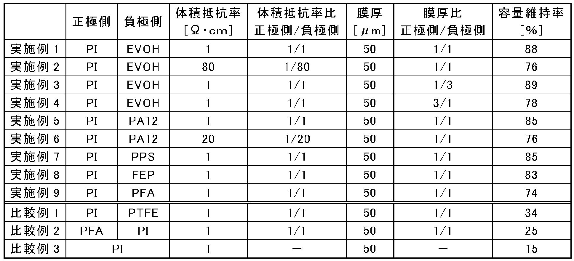
- the thickness ratio between the first conductive layer 3a and the second conductive layer 3b is not particularly limited, and the first conductive layer / second conductive layer is preferably 1000/1. To 1/1000, more preferably 100/1 to 1/100, further preferably 5/1 to 1/15, particularly preferably 2/1 to 1/5, and most preferably 1. / 1 to 1/4. When a value within such a range is selected, the barrier property against lithium ions and the electrolyte is sufficiently exhibited, which can contribute to the improvement of the battery capacity. In particular, when the second conductive layer 3b is thicker than the first conductive layer 3a, the lithium ion blocking property is more remarkably exhibited, and the battery capacity can be effectively prevented from decreasing.
- the upper limit value of the volume resistance of the current collector 3 is preferably 10 2 ⁇ ⁇ cm or less.
- the lower limit value of the volume resistance of the current collector 3 is preferably 10 ⁇ 5 ⁇ ⁇ cm or more from the viewpoint of reliability at the time of abnormality that suppresses current concentration to the short-circuited part at the time of a short circuit. More preferably, ⁇ 1 ⁇ ⁇ cm.
- the volume resistivity ratio values of the first conductive layer 3a (positive electrode side) and the second conductive layer 3b (negative electrode side) of the current collector 3 are preferably as positive electrode side / negative electrode side. Is 1/1000 to 1000/1, more preferably 1/100 to 100/1.
- the current collecting property which is the main function of the current collector 3 is sufficiently ensured, which can contribute to the improvement of the battery capacity.
- what is necessary is just to set suitably the kind and quantity of a conductive filler added to a base material (resin) when manufacturing a conductive layer, and a dispersion
- the value of volume resistance (ratio) is measured by the method as described in the Example mentioned later.
- the energy level of the highest occupied orbit (HOMO) of the conductive layer disposed on the negative electrode side of the bipolar electrode is raised by the supply of electrons based on the negative electrode potential.
- the present inventors have found that when the level after the increase exceeds the redox potential of lithium ions in the electrolyte, electrons move, and accordingly lithium ions penetrate into the resin current collector. .
- the current collector 3 of the present embodiment even if the energy level of the highest occupied orbit (HOMO) of the second conductive layer 3b disposed on the negative electrode side of the bipolar electrode is increased by the negative electrode potential, It is suppressed that the level after the rise exceeds the redox potential of lithium ions in the electrolytic solution. As a result, penetration and occlusion of lithium ions into the resin current collector are prevented (that is, lithium ion blocking properties are exhibited).
- HOMO highest occupied orbit
- the current collector 3 of the present embodiment is superior in terms of reliability in an abnormal state as compared with a resin current collector including a conventional metal layer.
- the positive electrode active material layer 5 contains a positive electrode active material.
- the positive electrode active material has a composition that occludes ions during discharging and releases ions during charging.
- a preferable example is a lithium-transition metal composite oxide that is a composite oxide of a transition metal and lithium.
- Li ⁇ Co-based composite oxide such as LiCoO 2
- Li ⁇ Ni-based composite oxide such as LiNiO 2
- Li ⁇ Mn-based composite oxide such as spinel LiMn 2 O 4
- Li ⁇ such LiFeO 2 Fe-based composite oxides and those obtained by replacing some of these transition metals with other elements can be used.
- These lithium-transition metal composite oxides are excellent in reactivity and cycle characteristics and are low-cost materials.
- examples of the positive electrode active material include transition metal oxides such as LiFePO 4 and lithium phosphate compounds and sulfuric acid compounds; transition metal oxides such as V 2 O 5 , MnO 2 , TiS 2 , MoS 2 , and MoO 3 , and sulfides. Materials; PbO 2 , AgO, NiOOH, etc. can also be used.
- the positive electrode active material may be used alone or in the form of a mixture of two or more.
- the average particle diameter of the positive electrode active material is not particularly limited, but is preferably 1 to 100 ⁇ m, more preferably 1 to 20 ⁇ m, from the viewpoint of increasing the capacity, reactivity, and cycle durability of the positive electrode active material. Within such a range, the secondary battery can suppress an increase in the internal resistance of the battery during charging and discharging under high output conditions, and can extract a sufficient current.
- the positive electrode active material is secondary particles, it can be said that the average particle diameter of the primary particles constituting the secondary particles is desirably in the range of 10 nm to 1 ⁇ m. It is not limited to.
- the positive electrode active material may not be a secondary particle formed by aggregation, agglomeration, or the like.
- the particle diameter of the positive electrode active material and the particle diameter of the primary particles a median diameter obtained using a laser diffraction method can be used.
- the shape of the positive electrode active material varies depending on the type and manufacturing method, and examples thereof include a spherical shape (powdered shape), a plate shape, a needle shape, a column shape, and a square shape, but are not limited thereto. Any shape can be used without any problems.
- an optimal shape that can improve battery characteristics such as charge / discharge characteristics is appropriately selected.
- the negative electrode active material layer 7 contains a negative electrode active material.
- the negative electrode active material has a composition capable of releasing ions during discharge and storing ions during charging.
- the negative electrode active material is not particularly limited as long as it can reversibly occlude and release lithium.
- the negative electrode active material examples include metals such as Si and Sn, TiO, Ti 2 O 3 , TiO 2 , or Metal oxides such as SiO 2 , SiO, SnO 2 , complex oxides of lithium and transition metals such as Li 4/3 Ti 5/3 O 4 or Li 7 MnN, Li—Pb alloys, Li—Al alloys , Li, or carbon materials such as natural graphite, artificial graphite, carbon black, activated carbon, carbon fiber, coke, soft carbon, or hard carbon. Moreover, it is preferable that a negative electrode active material contains the element alloyed with lithium.
- the negative electrode active material may be used alone or in the form of a mixture of two or more.
- the element alloying with lithium is not limited to the following, but specifically, Si, Ge, Sn, Pb, Al, In, Zn, H, Ca, Sr, Ba, Ru, Rh, Ir, Pd, Pt, Ag, Au, Cd, Hg, Ga, Tl, C, N, Sb, Bi, O, S, Se, Te, Cl, and the like.
- the average particle diameter of the negative electrode active material is not particularly limited, but is preferably 1 to 100 ⁇ m, more preferably 1 to 20 ⁇ m, from the viewpoint of increasing the capacity, reactivity, and cycle durability of the negative electrode active material. Within such a range, the secondary battery can suppress an increase in the internal resistance of the battery during charging and discharging under high output conditions, and can extract a sufficient current.
- the negative electrode active material is secondary particles, it can be said that the average particle diameter of the primary particles constituting the secondary particles is desirably in the range of 10 nm to 1 ⁇ m. It is not limited to. However, it goes without saying that, depending on the manufacturing method, the negative electrode active material may not be a secondary particle formed by aggregation, lump or the like.
- the particle diameter of the negative electrode active material and the particle diameter of the primary particles a median diameter obtained by using a laser diffraction method can be used.
- the shape of the negative electrode active material varies depending on the type and manufacturing method, and examples thereof include a spherical shape (powdered shape), a plate shape, a needle shape, a column shape, and a square shape, but are not limited thereto. Any shape can be used without any problems.
- an optimal shape that can improve battery characteristics such as charge / discharge characteristics is appropriately selected.
- the active material layers (5, 7) may contain other materials if necessary.
- a conductive aid, a binder, and the like can be included.
- a polymerization initiator for polymerizing the polymer may be included.
- Conductive aid refers to an additive blended to improve the conductivity of the active material layer.
- Examples of the conductive aid include carbon powders such as acetylene black, carbon black, ketjen black, and graphite, various carbon fibers such as vapor grown carbon fiber (VGCF; registered trademark), expanded graphite, and the like.
- VGCF vapor grown carbon fiber
- binder examples include polyvinylidene fluoride (PVDF), PI, PTFE, SBR, and a synthetic rubber binder.
- PVDF polyvinylidene fluoride
- PI polyvinylidene fluoride
- PTFE polyvinylidene fluoride
- SBR synthetic rubber binder
- the binder is not limited to these.
- the binder and the matrix polymer used as the gel electrolyte are the same, it is not necessary to use a binder.
- the compounding ratio of the components contained in the active material layer is not particularly limited.
- the blending ratio can be adjusted by appropriately referring to known knowledge about lithium ion secondary batteries.
- the thickness of the active material layer is not particularly limited, and conventionally known knowledge about the lithium ion secondary battery can be appropriately referred to.
- the thickness of the active material layer is preferably about 10 to 100 ⁇ m, more preferably 20 to 50 ⁇ m. If the active material layer is about 10 ⁇ m or more, the battery capacity can be sufficiently secured. On the other hand, when the active material layer is about 100 ⁇ m or less, it is possible to suppress the occurrence of the problem of an increase in internal resistance due to the difficulty of diffusing Li + into the electrode deep part (current collector side).
- the method for forming the positive electrode active material layer (or negative electrode active material layer) on the current collector surface is not particularly limited, and known methods can be used in the same manner.
- a positive electrode active material (or a negative electrode active material) and, if necessary, an electrolyte salt for increasing ion conductivity, a conductive auxiliary agent for increasing electron conductivity, and a binder are appropriately used.
- a positive electrode active material slurry (or a negative electrode active material slurry) is prepared by dispersing and dissolving in a solvent. This is applied onto a current collector, dried to remove the solvent, and then pressed to form a positive electrode active material layer (or negative electrode active material layer) on the current collector.
- the solvent is not particularly limited, and N-methyl-2-pyrrolidone (NMP), dimethylformamide, dimethylacetamide, methylformamide, cyclohexane, hexane, water and the like can be used.
- NMP N-methyl-2-pyrrolidone
- dimethylformamide dimethylacetamide
- methylformamide cyclohexane
- hexane water and the like
- PVdF polyvinylidene fluoride
- NMP is preferably used as a solvent.
- the positive electrode active material slurry (or the negative electrode active material slurry) is applied onto the current collector, dried, and then pressed.
- the porosity of the positive electrode active material layer (or the negative electrode active material layer) can be controlled by adjusting the pressing conditions.
- the specific means and press conditions for the press treatment are not particularly limited, and can be appropriately adjusted so that the porosity of the positive electrode active material layer (or the negative electrode active material layer) after the press treatment becomes a desired value.
- Specific examples of the press process include a hot press machine and a calendar roll press machine.
- the pressing conditions temperature, pressure, etc.
- conventionally known knowledge can be referred to as appropriate.
- the bipolar electrode 1 of the present embodiment even if the energy level of the highest occupied orbit (HOMO) of the second conductive layer 3b disposed on the negative electrode side of the bipolar electrode is increased by the negative electrode potential, It is suppressed that the level after an increase exceeds the oxidation-reduction potential of lithium ions in the electrolytic solution. As a result, penetration and occlusion of lithium ions into the resin current collector are prevented (that is, lithium ion blocking properties are exhibited).
- HOMO highest occupied orbit
- FIG. 2 is a cross-sectional view schematically showing the overall structure of a bipolar secondary battery according to an embodiment of the present invention.
- the bipolar secondary battery 10 of this embodiment shown in FIG. 2 has a structure in which a substantially rectangular power generation element 21 in which a charge / discharge reaction actually proceeds is sealed inside a laminate film 29 that is a battery exterior material. .
- the power generation element 21 of the bipolar secondary battery 10 of the present embodiment has a positive electrode active material layer 13 that is electrically coupled to one surface of the current collector 11. And a plurality of bipolar electrodes 23 having a negative electrode active material layer 15 electrically coupled to the opposite surface. Each bipolar electrode 23 is laminated via the electrolyte layer 17 to form the power generation element 21.
- the electrolyte layer 17 has a configuration in which an electrolyte is held at the center in the surface direction of a separator as a base material. At this time, the positive electrode active material layer 13 of one bipolar electrode 23 and the negative electrode active material layer 15 of another bipolar electrode 23 adjacent to the one bipolar electrode 23 face each other through the electrolyte layer 17.
- the bipolar electrodes 23 and the electrolyte layers 17 are alternately stacked. That is, the electrolyte layer 17 is interposed between the positive electrode active material layer 13 of one bipolar electrode 23 and the negative electrode active material layer 15 of another bipolar electrode 23 adjacent to the one bipolar electrode 23. ing.
- the adjacent positive electrode active material layer 13, electrolyte layer 17, and negative electrode active material layer 15 constitute one unit cell layer 19. Therefore, it can be said that the bipolar secondary battery 10 has a configuration in which the single battery layers 19 are stacked. Further, for the purpose of preventing liquid junction due to leakage of the electrolytic solution from the electrolyte layer 17, a seal portion (insulating layer) 31 is disposed on the outer peripheral portion of the unit cell layer 19.
- a positive electrode active material layer 13 is formed only on one side of the positive electrode outermost layer current collector 11 a located in the outermost layer of the power generation element 21.
- the negative electrode active material layer 15 is formed only on one surface of the outermost current collector 11b on the negative electrode side located in the outermost layer of the power generation element 21.
- a positive electrode current collector plate 25 is disposed adjacent to the outermost layer current collector 11a on the positive electrode side, and this is extended to form a laminate film 29 that is a battery exterior material.
- the negative electrode current collector plate 27 is disposed so as to be adjacent to the outermost layer current collector 11 b on the negative electrode side, and is similarly extended and led out from the laminate film 29.
- a seal portion 31 is usually provided around each single cell layer 19.
- the purpose of the seal portion 31 is to prevent the adjacent current collectors 11 in the battery from coming into contact with each other and a short circuit caused by a slight irregularity at the end of the unit cell layer 19 in the power generation element 21. Is provided. By installing such a seal portion 31, long-term reliability and safety are ensured, and a high-quality bipolar secondary battery 10 can be provided.
- the number of times the single battery layer 19 is stacked is adjusted according to the desired voltage. Further, in the bipolar secondary battery 10, the number of stacking of the single battery layers 19 may be reduced if a sufficient output can be secured even if the thickness of the battery is made as thin as possible. Even in the bipolar secondary battery 10, in order to prevent external impact and environmental degradation during use, the power generation element 21 is sealed under reduced pressure in a laminate film 29 that is a battery exterior material, and the positive electrode current collector plate 25 and the negative electrode current collector 25. A structure in which the electric plate 27 is taken out of the laminate film 29 is preferable.
- main components of the bipolar secondary battery of this embodiment will be described.
- Electrode layer There is no restriction
- the liquid electrolyte is a solution in which a lithium salt as a supporting salt is dissolved in a solvent.
- the solvent include dimethyl carbonate (DMC), diethyl carbonate (DEC), dipropyl carbonate (DPC), ethyl methyl carbonate (EMC), methyl propionate (MP), methyl acetate (MA), and methyl formate (MF).
- the supporting salt is not particularly limited, LiPF 6, LiBF 4, LiClO 4, LiAsF 6, LiTaF 6, LiSbF 6, LiAlCl 4, Li 2 B 10 Cl 10, LiI, LiBr, LiCl Inorganic acid anion salts such as LiAlCl, LiHF 2 and LiSCN, LiCF 3 SO 3 , Li (CF 3 SO 2 ) 2 N, LiBOB (lithium bisoxide borate), LiBETI (lithium bis (perfluoroethylenesulfonylimide); And organic acid anion salts such as Li (C 2 F 5 SO 2 ) 2 N).
- These electrolyte salts may be used alone or in the form of a mixture of two or more.
- the polymer electrolyte is classified into a gel electrolyte containing an electrolytic solution and a polymer solid electrolyte containing no electrolytic solution.
- the gel electrolyte has a configuration in which the liquid electrolyte is injected into a matrix polymer having Li + conductivity.
- the matrix polymer having Li + conductivity for example, a polymer having polyethylene oxide in the main chain or side chain (PEO), a polymer having polypropylene oxide in the main chain or side chain (PPO), polyethylene glycol (PEG), poly Acrylonitrile (PAN), polymethacrylic acid ester, polyvinylidene fluoride (PVdF), copolymer of polyvinylidene fluoride and hexafluoropropylene (PVdF-HFP), polyacrylonitrile (PAN), poly (methyl acrylate) (PMA), poly (Methyl methacrylate) (PMMA) etc. are mentioned.
- PEO polymer having polyethylene oxide in the main chain or side chain
- PPO polymer having polypropylene oxide in the main chain or side chain
- PEG polyethylene glycol
- PAN poly Acrylonitrile
- PVdF polymethacrylic acid ester
- PVdF polyvinylidene fluoride
- mixtures of the above-described polymers, modified products, derivatives, random copolymers, alternating copolymers, graft copolymers, block copolymers, and the like can also be used.
- PEO, PPO and their copolymers, PVdF, PVdF-HFP it is desirable to use PEO, PPO and their copolymers, PVdF, PVdF-HFP.
- an electrolyte salt such as a lithium salt can be well dissolved.
- a separator may be used for the electrolyte layer.
- the separator include a microporous film made of polyolefin such as polyethylene or polypropylene, hydrocarbon such as polyvinylidene fluoride-hexafluoropropylene (PVdF-HFP), glass fiber, or the like.
- the polymer solid electrolyte has a structure in which a supporting salt (lithium salt) is dissolved in the above matrix polymer, and does not include an organic solvent that is a plasticizer. Therefore, when the electrolyte layer is composed of a polymer solid electrolyte, there is no fear of liquid leakage from the battery, and the battery reliability can be improved.
- a supporting salt lithium salt
- a matrix polymer of a polymer gel electrolyte or a polymer solid electrolyte can exhibit excellent mechanical strength by forming a crosslinked structure.
- thermal polymerization, ultraviolet polymerization, radiation polymerization, electron beam polymerization, etc. are performed on a polymerizable polymer (for example, PEO or PPO) for forming a polymer electrolyte, using an appropriate polymerization initiator.
- a polymerization treatment may be performed.
- the said electrolyte may be contained in the active material layer of an electrode.
- the seal portion has a function of preventing contact between current collectors and a short circuit at the end of the single cell layer.
- urethane resin, epoxy resin, polyethylene resin, polypropylene resin, polyimide resin, rubber and the like can be used.
- polyethylene resin and polypropylene resin are preferably used as the constituent material of the insulating layer from the viewpoints of corrosion resistance, chemical resistance, ease of production (film forming property), economy, and the like.
- battery exterior materials As the battery exterior material, a conventionally known metal can case can be used, and a bag-like case using a laminate film containing aluminum that can cover the power generation element can be used.
- a laminate film having a three-layer structure in which polypropylene, aluminum, and nylon are laminated in this order can be used as the laminate film, but the laminate film is not limited thereto.
- a laminate film that is excellent in high output and cooling performance and can be suitably used for a battery for large equipment such as for EV and HEV is desirable.
- the energy level of the highest occupied orbit (HOMO) of the second conductive layer 3b disposed on the negative electrode side of the bipolar electrode is increased by the negative electrode potential.
- the level after the rise exceeds the redox potential of lithium ions in the electrolytic solution.
- penetration and occlusion of lithium ions into the resin current collector are prevented (that is, lithium ion blocking properties are exhibited).
- a liquid junction between the active material layers and a decrease in battery capacity associated therewith can be suppressed.
- Example 1 ⁇ Preparation of current collector>
- a conductive resin film (film thickness: 25 ⁇ m) prepared by mixing 10% by mass of ketjen black with 100% by mass of polyimide (PI) was prepared.
- the first conductive layer and the second conductive layer prepared and produced above are superposed and thermally fused at 160 ° C. for 10 minutes.
- a current collector was produced.
- PVDF polyvinylidene fluoride
- NMP N-methyl-2-pyrrolidone
- the positive electrode active material slurry prepared above was applied to the surface of the current collector prepared above on the first conductive layer side and dried to form a coating film. At this time, a peripheral portion of the current collector was exposed in order to arrange a seal portion (described later). The obtained coating film was subjected to a press treatment to form a positive electrode active material layer (thickness: 36 ⁇ m).
- the negative electrode active material slurry prepared above was applied to the surface of the current collector prepared above on the second conductive layer side and dried to form a coating film. At this time, a peripheral portion of the current collector was exposed in order to arrange a seal portion (described later). The obtained coating film was pressed to form a negative electrode active material layer (thickness: 30 ⁇ m).
- the LiPF 6 is a lithium salt in an equal volume mixture of propylene carbonate, ethylene carbonate as an electrolyte was dissolved at a concentration of 1 mol / L. Further, 90% by mass of this electrolytic solution, 10% by mass of a polyvinylidene fluoride-hexafluoropropylene (PVDF-HFP) copolymer containing 10 mol% of hexafluoropropylene comonomer as a host polymer, and dimethyl carbonate as a viscosity adjusting solvent (DMC) An appropriate amount was mixed to prepare an electrolyte material.
- PVDF-HFP polyvinylidene fluoride-hexafluoropropylene copolymer containing 10 mol% of hexafluoropropylene comonomer as a host polymer
- DMC viscosity adjusting solvent
- the electrolyte material prepared above is applied to each surface of the positive electrode active material layer and the negative electrode active material layer of the bipolar electrode prepared above, and the DMC is dried at 100 ° C. so that the gel electrolyte is in the active material layer. Completed a bipolar electrode that penetrated into.
- a high voltage terminal in which a part of a 130 mm ⁇ 80 mm aluminum plate (thickness: 100 ⁇ m) capable of covering the entire projection surface of the obtained power generation element extends to the outside of the projection surface of the power generation element was created.
- the power generation element is sandwiched between these high power terminals, vacuum-sealed with an aluminum laminate film so as to cover them, and the entire surface of the power generation element is pressurized by pressing it at atmospheric pressure to enhance the contact between the high power terminal and the power generation element.
- a laminated structure was obtained.
- the laminated structure obtained above is subjected to hot pressing in the laminating direction (surface pressure 1 kg / cm 2 , 150 ° C., 1 hour), the uncured seal portion is cured, and a bipolar secondary battery is obtained. Completed.
- Example 2 A bipolar secondary battery is produced in the same manner as in Example 1 except that the amount of ketjen black used for producing the second conductive layer is 5% by mass with respect to 100% by mass of EVOH. Was made.
- Example 3 Example 1 described above, except that a first conductive layer having a thickness of 12.5 ⁇ m was used and that the second conductive layer was formed to have a thickness of 37.5 ⁇ m.
- a bipolar secondary battery was produced by the same method as described above.
- Example 4 Example 1 described above, except that a first conductive layer having a thickness of 37.5 ⁇ m was used and that the second conductive layer was formed to have a thickness of 12.5 ⁇ m.
- a bipolar secondary battery was produced by the same method as described above.
- Example 5 The same method as in Example 1 described above, except that nylon 12 (PA12) was used instead of EVOH when the second conductive layer was produced, and that the heat fusion temperature was 170 ° C. Thus, a bipolar secondary battery was produced.
- nylon 12 PA12
- Example 6 A bipolar secondary is produced in the same manner as in Example 5 except that the amount of ketjen black used for producing the second conductive layer is 7% by mass with respect to 100% by mass of PA12. A battery was produced.
- Example 7 The same method as in Example 1 described above, except that polyphenylene sulfide (PPS) was used instead of EVOH when the second conductive layer was produced, and that the thermal fusion temperature was 250 ° C. Thus, a bipolar secondary battery was produced.
- PPS polyphenylene sulfide
- Example 8 Except for using tetrafluoroethylene-hexafluoropropylene copolymer (FEP) instead of EVOH when the second conductive layer was produced, and that the heat-sealing temperature was 250 ° C.
- FEP tetrafluoroethylene-hexafluoropropylene copolymer
- Example 9 A bipolar type was produced in the same manner as in Example 1 except that tetrafluoroethylene-perfluoroalkyl vinyl ether copolymer (PFA) was used instead of EVOH when producing the second conductive layer. A secondary battery was produced.
- PFA tetrafluoroethylene-perfluoroalkyl vinyl ether copolymer
- Example 1 A bipolar secondary battery was produced in the same manner as in Example 1 except that polytetrafluoroethylene (PTFE) was used in place of EVOH when producing the second conductive layer.
- PTFE polytetrafluoroethylene
- PTFE is a polymer that does not have an imide group but does not have a polar group.
- Example 2 Except that the negative electrode active material layer was formed on the surface of the current collector on the first conductive layer side and the positive electrode active material layer was formed on the surface of the second conductive layer side, the same as Example 9 described above A bipolar secondary battery was fabricated by the method described above.
- volume resistivity was measured by the following method. First, the current collector was cut into a size of 5 cm ⁇ 8 cm, and the surface resistance value was measured using a four-probe probe (manufactured by Mitsubishi Chemical Corporation: Loresta-EP model number: MCP-T360) at nine points in the plane. The obtained value was normalized by the film thickness, and the volume resistivity ( ⁇ ⁇ cm) was calculated. Similarly, the volume resistivity on the positive electrode side and the negative electrode side was measured, and the volume resistivity ratio was calculated. These results are shown in Table 1 below.
Landscapes
- Chemical & Material Sciences (AREA)
- Engineering & Computer Science (AREA)
- Chemical Kinetics & Catalysis (AREA)
- Electrochemistry (AREA)
- General Chemical & Material Sciences (AREA)
- Materials Engineering (AREA)
- Manufacturing & Machinery (AREA)
- Composite Materials (AREA)
- Cell Electrode Carriers And Collectors (AREA)
- Secondary Cells (AREA)
- Battery Electrode And Active Subsutance (AREA)
Abstract
Description
図1は、本発明の一実施形態に係る双極型リチウムイオン二次電池用集電体を用いた、リチウムイオン二次電池用双極型電極の全体構造を模式的に表した断面図である。図1に示す本実施形態の双極型電極1は、集電体3の一方の面に正極活物質層5が形成され、他方の面に負極活物質層7が形成された積層構造を有する。そして、集電体3は、正極活物質層5側に位置する第1の導電性層3aと、負極活物質層7側に位置する第2の導電性層3bとが積層されてなる2層構造を有する。
集電体3は、正極活物質層が形成される一方の面から、負極活物質層が形成される他方の面へと電子の移動を媒介する機能を有する。
第2の導電性層3bにおいて、基材は、極性を有するイミド基非含有樹脂を含む。本実施形態において、極性を有するイミド基非含有樹脂は、集電体3へのリチウムイオンの浸透および吸蔵を抑制するのに寄与する。ここで、イミド基非含有樹脂が「極性」を有するとは、当該樹脂が全体として極性を有することを意味する。この場合、イミド基非含有樹脂は例えば、極性基またはその誘導体を有する。「極性基」とは、極性を有する原子団を意味する。また、「極性基の誘導体」とは、上述した「極性基」へのさらなる官能基の導入や原子の置換により、母体の構造を大幅に変更しない程度の改変がなされたものを意味する。したがって、第2の導電性層3bを構成するイミド基非含有樹脂は、これらの極性基またはその誘導体を有することで樹脂自体も極性を有するようになる。イミド基非含有樹脂に極性を付与しうる極性基としては、例えば、ヒドロキシ基、アミド基、スルフィド基、フッ素原子などのハロゲン原子、エーテル基、アミノ基などが挙げられるが、これらに限定されるわけではない。このような極性を有するイミド基非含有樹脂は、樹脂中の分子間力(イオン間相互作用、水素結合など)が大きいため、リチウムイオンが集電体3の内部へ透過するのを防ぐことができる。
正極活物質層5は正極活物質を含む。正極活物質は、放電時にイオンを吸蔵し、充電時にイオンを放出する組成を有する。好ましい一例としては、遷移金属とリチウムとの複合酸化物であるリチウム-遷移金属複合酸化物が挙げられる。具体的には、LiCoO2などのLi・Co系複合酸化物、LiNiO2などのLi・Ni系複合酸化物、スピネルLiMn2O4などのLi・Mn系複合酸化物、LiFeO2などのLi・Fe系複合酸化物およびこれらの遷移金属の一部を他の元素により置換したものなどが使用できる。これらリチウム-遷移金属複合酸化物は、反応性、サイクル特性に優れ、低コストな材料である。そのためこれらの材料を電極に用いることにより、出力特性に優れた電池を形成することが可能である。この他、前記正極活物質としては、LiFePO4などの遷移金属とリチウムのリン酸化合物や硫酸化合物;V2O5、MnO2、TiS2、MoS2、MoO3などの遷移金属酸化物や硫化物;PbO2、AgO、NiOOHなど、を用いることもできる。上記正極活物質は、単独で使用されてもあるいは2種以上の混合物の形態で使用されてもよい。
負極活物質層7は負極活物質を含む。負極活物質は、放電時にイオンを放出し、充電時にイオンを吸蔵できる組成を有する。負極活物質は、リチウムを可逆的に吸蔵および放出できるものであれば特に制限されないが、負極活物質の例としては、SiやSnなどの金属、あるいはTiO、Ti2O3、TiO2、もしくはSiO2、SiO、SnO2などの金属酸化物、Li4/3Ti5/3O4もしくはLi7MnNなどのリチウムと遷移金属との複合酸化物、Li-Pb系合金、Li-Al系合金、Li、または天然黒鉛、人造黒鉛、カーボンブラック、活性炭、カーボンファイバー、コークス、ソフトカーボン、もしくはハードカーボンなどの炭素材料などが好ましく挙げられる。また、負極活物質は、リチウムと合金化する元素を含むことが好ましい。リチウムと合金化する元素を用いることにより、従来の炭素系材料に比べて高いエネルギー密度を有する高容量および優れた出力特性の電池を得ることが可能となる。上記負極活物質は、単独で使用されてもあるいは2種以上の混合物の形態で使用されてもよい。
図2は、本発明の一実施形態である双極型二次電池の全体構造を模式的に表した断面図である。図2に示す本実施形態の双極型二次電池10は、実際に充放電反応が進行する略矩形の発電要素21が、電池外装材であるラミネートフィルム29の内部に封止された構造を有する。
電解質層を構成する電解質に特に制限はなく、液体電解質、ならびに高分子ゲル電解質および高分子固体電解質等のポリマー電解質を適宜用いることができる。
シール部(絶縁層)は、集電体同士の接触や単電池層の端部における短絡を防止する機能を有する。シール部を構成する材料としては、絶縁性、固体電解質の脱落に対するシール性や外部からの水分の透湿に対するシール性(密封性)、電池動作温度下での耐熱性等を有するものであればよい。例えば、ウレタン樹脂、エポキシ樹脂、ポリエチレン樹脂、ポリプロピレン樹脂、ポリイミド樹脂、ゴム等が用いられうる。なかでも、耐蝕性、耐薬品性、作り易さ(製膜性)、経済性等の観点から、ポリエチレン樹脂やポリプロピレン樹脂が、絶縁層の構成材料として好ましく用いられる。
電池外装材としては、従来公知の金属缶ケースを用いることができるほか、発電要素を覆うことができる、アルミニウムを含むラミネートフィルムを用いた袋状のケースが用いられうる。該ラミネートフィルムには、例えば、ポリプロピレン、アルミニウム、ナイロンをこの順に積層してなる3層構造のラミネートフィルム等を用いることができるが、これらに何ら制限されるものではない。本形態では、高出力化や冷却性能に優れ、EV、HEV用等の大型機器用電池に好適に利用することができるラミネートフィルムが望ましい。
<集電体の作製>
第1の導電性層として、ポリイミド(PI)100質量%に対してケッチェンブラック10質量%が混合されてなる導電性樹脂フィルム(膜厚:25μm)を準備した。
正極活物質としてLiMn2O4 85質量%、導電助剤としてアセチレンブラック5質量%、バインダとしてポリフッ化ビニリデン(PVDF)10質量%、およびスラリー粘度調整溶媒としてN-メチル-2-ピロリドン(NMP)適量を混合し、正極活物質スラリーを調製した。
上記で得られた双極型電極の正極活物質層上に上記で調製した電解質材料を塗布し、100℃にてDMCを乾燥させて、ゲル電解質層を形成した。一方、集電体の第1の導電性層側の表面の露出部(周縁部)に幅12mmのシール材を配置した。この操作を繰り返して、6つの双極型電極がゲル電解質層を介して積層されてなる積層体を得た。次いで、得られた積層体に対して積層方向にホットプレス処理(0.2MPa、80℃、5秒間)を施し、シール部を融着させることで隣接する双極型電極間をシールして、発電要素を完成させた。
第2の導電性層を作製する際のケッチェンブラックの配合量を、EVOH100質量%に対して5質量%としたこと以外は、上述した実施例1と同様の手法により、双極型二次電池を作製した。
第1の導電性層として、膜厚12.5μmのものを用いたこと、および、第2の導電性層を膜厚が37.5μmとなるように作製したこと以外は、上述した実施例1と同様の手法により、双極型二次電池を作製した。
第1の導電性層として、膜厚37.5μmのものを用いたこと、および、第2の導電性層を膜厚が12.5μmとなるように作製したこと以外は、上述した実施例1と同様の手法により、双極型二次電池を作製した。
第2の導電性層を作製する際に、EVOHに代えてナイロン12(PA12)を用いたこと、および、熱融着温度を170℃としたこと以外は、上述した実施例1と同様の手法により、双極型二次電池を作製した。
第2の導電性層を作製する際のケッチェンブラックの配合量を、PA12 100質量%に対して7質量%としたこと以外は、上述した実施例5と同様の手法により、双極型二次電池を作製した。
第2の導電性層を作製する際に、EVOHに代えてポリフェニレンスルフィド(PPS)を用いたこと、および、熱融着温度を250℃としたこと以外は、上述した実施例1と同様の手法により、双極型二次電池を作製した。
第2の導電性層を作製する際に、EVOHに代えてテトラフルオロエチレン-ヘキサフルオロプロピレン共重合体(FEP)を用いたこと、および、熱融着温度を250℃としたこと以外は、上述した実施例1と同様の手法により、双極型二次電池を作製した。
第2の導電性層を作製する際に、EVOHに代えてテトラフルオロエチレン-パーフロロアルキルビニルエーテル共重合体(PFA)を用いたこと以外は、上述した実施例1と同様の手法により、双極型二次電池を作製した。
第2の導電性層を作製する際に、EVOHに代えてポリテトラフルオロエチレン(PTFE)を用いたこと以外は、上述した実施例1と同様の手法により、双極型二次電池を作製した。なお、PTFEはイミド基を有しないが、極性基をも有しないポリマーである。
集電体の第1の導電性層側の表面に負極活物質層を形成し、第2の導電性層側の表面に正極活物質層を形成したこと以外は、上述した実施例9と同様の手法により、双極型二次電池を作製した。
集電体として、ポリイミド(PI)100質量%に対してケッチェンブラック10質量%が混合されてなる導電性樹脂フィルム(膜厚:50μm)を用いたこと以外は、上述した実施例1と同様の手法により、双極型二次電池を作製した。なお、本比較例において用いた集電体は単層であることから、正極側・負極側の区別はない。
上記の方法で作製した各双極型二次電池について、25℃の雰囲気下、0.5mAの電流で21.0Vまで定電流充電(CC)し、その後定電圧で充電(CV)し、合計で10時間充電した。その後、1Cの放電容量で50サイクルの耐久試験を行い、耐久試験終了後の容量測定を行った。初充電時に対する耐久試験終了後の容量の百分率(%)を容量維持率とした。結果を下記の表1に示す。
上述した各実施例および各比較例で用いた集電体について、以下の手法により体積抵抗率を測定した。まず、集電体を5cm×8cmのサイズに裁断し、面内9点を4探針プローブ(三菱化学株式会社製:Loresta-EP 型番:MCP-T360)を用いて表面抵抗値を計測し、得られた値を膜厚で規格化して、体積抵抗率(Ω・cm)を算出した。また、同様にして正極側と負極側との体積抵抗率をそれぞれ計測し、体積抵抗率比お算出した。これらの結果を下記の表1に示す。
3、11 集電体、
3a 第1の導電性層、
3b 第2の導電性層、
5、13 正極活物質層、
7、15 負極活物質層、
10 双極型二次電池、
11a 正極側の最外層集電体、
11b 負極側の最外層集電体、
17 電解質層、
19 単電池層、
21 発電要素、
25 正極集電板、
27 負極集電板、
29 ラミネートフィルム、
31 シール部。
Claims (5)
- イミド基含有樹脂を含む基材に導電性フィラーが添加されてなる第1の導電性層と、
極性を有するイミド基非含有樹脂を含む基材に導電性フィラーが添加されてなる第2の導電性層と、
を有し、前記第1の導電性層が正極側に位置するように用いられる、双極型リチウムイオン二次電池用集電体。 - 前記第2の導電性層が、前記第1の導電性層よりも厚い、請求項1に記載の双極型リチウムイオン二次電池用集電体。
- 前記イミド基非含有樹脂が、結晶性である、請求項1または2に記載の双極型リチウムイオン二次電池用集電体。
- 請求項1~3のいずれか1項に記載の集電体と、
前記集電体の前記第1の導電性層側の面に形成された正極活物質層と、
前記集電体の前記第2の導電性層側の面に形成された負極活物質層と、
を有する、双極型リチウムイオン二次電池用電極。 - 請求項4に記載の電極と電解質層とが積層されてなる発電要素を有する、双極型リチウムイオン二次電池。
Priority Applications (5)
| Application Number | Priority Date | Filing Date | Title |
|---|---|---|---|
| KR1020127006505A KR101322584B1 (ko) | 2010-01-29 | 2010-12-06 | 쌍극형 리튬 이온 2차 전지용 집전체 |
| CN201080040928.2A CN102511098B (zh) | 2010-01-29 | 2010-12-06 | 双极型锂离子二次电池用集电体 |
| JP2011551693A JP5375978B2 (ja) | 2010-01-29 | 2010-12-06 | 双極型リチウムイオン二次電池用集電体 |
| US13/395,565 US9077040B2 (en) | 2010-01-29 | 2010-12-06 | Collector having multiple resin layers for bipolar lithium ion secondary battery |
| EP10844692.3A EP2530769B1 (en) | 2010-01-29 | 2010-12-06 | Collector for bipolar lithium ion secondary battery |
Applications Claiming Priority (2)
| Application Number | Priority Date | Filing Date | Title |
|---|---|---|---|
| JP2010018722 | 2010-01-29 | ||
| JP2010-018722 | 2010-01-29 |
Publications (1)
| Publication Number | Publication Date |
|---|---|
| WO2011092938A1 true WO2011092938A1 (ja) | 2011-08-04 |
Family
ID=44318939
Family Applications (1)
| Application Number | Title | Priority Date | Filing Date |
|---|---|---|---|
| PCT/JP2010/071825 Ceased WO2011092938A1 (ja) | 2010-01-29 | 2010-12-06 | 双極型リチウムイオン二次電池用集電体 |
Country Status (6)
| Country | Link |
|---|---|
| US (1) | US9077040B2 (ja) |
| EP (1) | EP2530769B1 (ja) |
| JP (1) | JP5375978B2 (ja) |
| KR (1) | KR101322584B1 (ja) |
| CN (1) | CN102511098B (ja) |
| WO (1) | WO2011092938A1 (ja) |
Cited By (7)
| Publication number | Priority date | Publication date | Assignee | Title |
|---|---|---|---|---|
| JP2013026192A (ja) * | 2011-07-26 | 2013-02-04 | Nissan Motor Co Ltd | 双極型リチウムイオン二次電池用集電体 |
| WO2013125410A1 (ja) * | 2012-02-23 | 2013-08-29 | 日産自動車株式会社 | 双極型電極およびこれを用いた双極型リチウムイオン二次電池 |
| WO2014053985A1 (fr) | 2012-10-01 | 2014-04-10 | Commissariat A L'energie Atomique Et Aux Energies Alternatives | Collecteur de courant avec moyens d'étanchéité intégrés, batterie bipolaire comprenant un tel collecteur, procédé de réalisation d'une telle batterie |
| US9905882B2 (en) * | 2012-11-22 | 2018-02-27 | Samsung Sdi Co., Ltd. | Positive active material layer for rechargeable lithium battery, separator for rechargeable lithium battery, and rechargeable lithium battery including at least one of same |
| US10431830B2 (en) * | 2012-08-30 | 2019-10-01 | Kaneka Corporation | Current collector for battery and battery using same |
| JP2024037018A (ja) * | 2022-09-06 | 2024-03-18 | トヨタ自動車株式会社 | 樹脂集電体、及び積層電池 |
| WO2024181287A1 (ja) | 2023-02-28 | 2024-09-06 | 東レ株式会社 | ポリエステルフィルム、樹脂集電体、双極型電池用樹脂集電体、双曲型電池用電極、蓄電素子、二次電池、電動自動車、および電動飛翔体 |
Families Citing this family (20)
| Publication number | Priority date | Publication date | Assignee | Title |
|---|---|---|---|---|
| MY165723A (en) * | 2011-05-23 | 2018-04-20 | Kaneka Corp | Conductive film, current collector using same, battery and bipolar battery |
| JP6217647B2 (ja) * | 2012-11-22 | 2017-10-25 | 株式会社カネカ | 双極型リチウムイオン二次電池用集電体および双極型リチウムイオン二次電池 |
| WO2016031690A1 (ja) * | 2014-08-25 | 2016-03-03 | 日産自動車株式会社 | 電極 |
| KR102349957B1 (ko) * | 2014-09-05 | 2022-01-11 | 삼성전자주식회사 | 유무기 실리콘 구조체 함유 블록 공중합체, 이를 포함하는 전해질, 및 상기 전해질을 포함하는 리튬전지 |
| JP2016096297A (ja) * | 2014-11-17 | 2016-05-26 | イビデン株式会社 | 金属塊内蔵配線板及びその製造方法 |
| JP6430875B2 (ja) * | 2015-03-27 | 2018-11-28 | 日産自動車株式会社 | リチウム電池用正極 |
| TWI618287B (zh) * | 2015-07-23 | 2018-03-11 | Copolymer of lithium battery and its positive electrode coating | |
| EP3422442B1 (en) | 2016-02-24 | 2020-04-08 | Nissan Motor Co., Ltd. | Electrode for lithium ion secondary battery and production method therefor |
| JP6705358B2 (ja) * | 2016-10-17 | 2020-06-03 | 株式会社豊田自動織機 | 蓄電装置の製造方法 |
| CN106898825B (zh) * | 2017-05-03 | 2019-02-05 | 江苏强劲新能源科技有限公司 | 一种双极性锌离子电池的制备方法 |
| CN107452929A (zh) * | 2017-07-26 | 2017-12-08 | 王昌国 | 一种电动汽车锂离子电池 |
| CN107394278A (zh) * | 2017-07-26 | 2017-11-24 | 王昌国 | 一种电动汽车锂离子电池的制造方法 |
| US10770731B2 (en) * | 2018-08-01 | 2020-09-08 | Chongqing Jinmei New Material Technology Co., Ltd. | Positive electrode current collector and preparation method and use thereof |
| JP7192866B2 (ja) * | 2018-08-10 | 2022-12-20 | 株式会社村田製作所 | 固体電池 |
| CN109768334A (zh) * | 2018-12-25 | 2019-05-17 | 中国电子科技集团公司第十八研究所 | 一种双极性固态锂二次电池的制备方法 |
| CN112186196B (zh) * | 2019-07-01 | 2023-10-27 | 宁德时代新能源科技股份有限公司 | 正极集流体、正极极片及电化学装置 |
| CN115176363B (zh) | 2020-02-26 | 2025-05-30 | 株式会社村田制作所 | 导电性基体以及二次电池 |
| CN111403749B (zh) | 2020-06-03 | 2020-09-01 | 江苏时代新能源科技有限公司 | 锂离子电池及其装置 |
| CN113871626B (zh) * | 2021-09-06 | 2023-03-14 | 湖南领湃达志科技股份有限公司 | 一种二次电池双极集流体及其制造工艺 |
| CA3238946A1 (en) * | 2021-12-02 | 2023-06-08 | Kam Piu Ho | Modified current collector for secondary battery |
Citations (3)
| Publication number | Priority date | Publication date | Assignee | Title |
|---|---|---|---|---|
| JP2006185854A (ja) * | 2004-12-28 | 2006-07-13 | Nissan Motor Co Ltd | バイポーラ電池 |
| JP2006190649A (ja) | 2004-12-07 | 2006-07-20 | Nissan Motor Co Ltd | バイポーラ電池およびその製造方法 |
| JP2006302616A (ja) * | 2005-04-19 | 2006-11-02 | Nissan Motor Co Ltd | バイポーラ電池 |
Family Cites Families (6)
| Publication number | Priority date | Publication date | Assignee | Title |
|---|---|---|---|---|
| US6280873B1 (en) | 1999-04-08 | 2001-08-28 | Quallion, Llc | Wound battery and method for making it |
| JP4674434B2 (ja) | 2002-11-11 | 2011-04-20 | 日産自動車株式会社 | バイポーラ電池 |
| JP5292676B2 (ja) * | 2006-06-07 | 2013-09-18 | 日産自動車株式会社 | 双極型電池用電極 |
| CN101192669A (zh) * | 2006-12-01 | 2008-06-04 | 中国人民解放军63971部队 | 一种耐腐蚀复合集流体及其制作方法 |
| JP5381078B2 (ja) * | 2008-12-19 | 2014-01-08 | 日産自動車株式会社 | 電極およびその製造方法 |
| JP5410822B2 (ja) | 2009-04-22 | 2014-02-05 | 日産自動車株式会社 | 双極型電池用集電体 |
-
2010
- 2010-12-06 CN CN201080040928.2A patent/CN102511098B/zh active Active
- 2010-12-06 WO PCT/JP2010/071825 patent/WO2011092938A1/ja not_active Ceased
- 2010-12-06 KR KR1020127006505A patent/KR101322584B1/ko not_active Expired - Fee Related
- 2010-12-06 EP EP10844692.3A patent/EP2530769B1/en active Active
- 2010-12-06 JP JP2011551693A patent/JP5375978B2/ja active Active
- 2010-12-06 US US13/395,565 patent/US9077040B2/en active Active
Patent Citations (3)
| Publication number | Priority date | Publication date | Assignee | Title |
|---|---|---|---|---|
| JP2006190649A (ja) | 2004-12-07 | 2006-07-20 | Nissan Motor Co Ltd | バイポーラ電池およびその製造方法 |
| JP2006185854A (ja) * | 2004-12-28 | 2006-07-13 | Nissan Motor Co Ltd | バイポーラ電池 |
| JP2006302616A (ja) * | 2005-04-19 | 2006-11-02 | Nissan Motor Co Ltd | バイポーラ電池 |
Non-Patent Citations (1)
| Title |
|---|
| See also references of EP2530769A4 * |
Cited By (14)
| Publication number | Priority date | Publication date | Assignee | Title |
|---|---|---|---|---|
| JP2013026192A (ja) * | 2011-07-26 | 2013-02-04 | Nissan Motor Co Ltd | 双極型リチウムイオン二次電池用集電体 |
| WO2013125410A1 (ja) * | 2012-02-23 | 2013-08-29 | 日産自動車株式会社 | 双極型電極およびこれを用いた双極型リチウムイオン二次電池 |
| JP2013175308A (ja) * | 2012-02-23 | 2013-09-05 | Nissan Motor Co Ltd | 双極型電極およびこれを用いた双極型リチウムイオン二次電池 |
| CN104106158A (zh) * | 2012-02-23 | 2014-10-15 | 日产自动车株式会社 | 双极型电极及使用其的双极型锂离子二次电池 |
| CN104106158B (zh) * | 2012-02-23 | 2016-10-26 | 日产自动车株式会社 | 双极型电极及使用其的双极型锂离子二次电池 |
| US10431830B2 (en) * | 2012-08-30 | 2019-10-01 | Kaneka Corporation | Current collector for battery and battery using same |
| US10497941B2 (en) | 2012-10-01 | 2019-12-03 | Commissariat A L'energie Atomique Et Aux Energies Alternatives | Current collector having a built-in sealing means, bipolar battery including such a collector, method for manufacturing such a battery |
| WO2014053985A1 (fr) | 2012-10-01 | 2014-04-10 | Commissariat A L'energie Atomique Et Aux Energies Alternatives | Collecteur de courant avec moyens d'étanchéité intégrés, batterie bipolaire comprenant un tel collecteur, procédé de réalisation d'une telle batterie |
| US9905882B2 (en) * | 2012-11-22 | 2018-02-27 | Samsung Sdi Co., Ltd. | Positive active material layer for rechargeable lithium battery, separator for rechargeable lithium battery, and rechargeable lithium battery including at least one of same |
| JP2024037018A (ja) * | 2022-09-06 | 2024-03-18 | トヨタ自動車株式会社 | 樹脂集電体、及び積層電池 |
| JP7718360B2 (ja) | 2022-09-06 | 2025-08-05 | トヨタ自動車株式会社 | 樹脂集電体、及び積層電池 |
| WO2024181287A1 (ja) | 2023-02-28 | 2024-09-06 | 東レ株式会社 | ポリエステルフィルム、樹脂集電体、双極型電池用樹脂集電体、双曲型電池用電極、蓄電素子、二次電池、電動自動車、および電動飛翔体 |
| KR20250160119A (ko) | 2023-02-28 | 2025-11-11 | 도레이 카부시키가이샤 | 폴리에스테르 필름, 수지 집전체, 쌍극형 전지용 수지 집전체, 쌍극형 전지용 전극, 축전 소자, 2차전지, 전동 자동차, 및 전동 비상체 |
| EP4674896A1 (en) | 2023-02-28 | 2026-01-07 | Toray Industries, Inc. | Polyester film, resin current-collector, resin current-collector for bipolar battery, electrode for hyperbolic battery, energy storage element, secondary battery, electric vehicle, and electric flying object |
Also Published As
| Publication number | Publication date |
|---|---|
| JP5375978B2 (ja) | 2013-12-25 |
| EP2530769A1 (en) | 2012-12-05 |
| KR101322584B1 (ko) | 2013-10-28 |
| EP2530769B1 (en) | 2016-10-19 |
| US20120189912A1 (en) | 2012-07-26 |
| CN102511098A (zh) | 2012-06-20 |
| EP2530769A4 (en) | 2013-08-28 |
| KR20120043104A (ko) | 2012-05-03 |
| CN102511098B (zh) | 2015-02-18 |
| US9077040B2 (en) | 2015-07-07 |
| JPWO2011092938A1 (ja) | 2013-05-30 |
Similar Documents
| Publication | Publication Date | Title |
|---|---|---|
| JP5375978B2 (ja) | 双極型リチウムイオン二次電池用集電体 | |
| JP5770553B2 (ja) | 双極型リチウムイオン二次電池用集電体 | |
| JP5177301B2 (ja) | 双極型二次電池用集電体 | |
| JP5333576B2 (ja) | 双極型二次電池及びその製造方法 | |
| JP5504708B2 (ja) | 双極型二次電池 | |
| JP5458605B2 (ja) | 双極型二次電池 | |
| JP5381292B2 (ja) | 双極型電極およびこれを用いた双極型二次電池 | |
| JP5957947B2 (ja) | 双極型電極およびこれを用いた双極型リチウムイオン二次電池 | |
| JP5417867B2 (ja) | 双極型二次電池 | |
| JP5593984B2 (ja) | 二次電池用集電体 | |
| JP5402116B2 (ja) | 双極型リチウムイオン二次電池用集電体 | |
| JP2011171185A (ja) | 二次電池用集電体 | |
| JP5569229B2 (ja) | リチウムイオン二次電池のニッケル含有正極用集電体 |
Legal Events
| Date | Code | Title | Description |
|---|---|---|---|
| WWE | Wipo information: entry into national phase |
Ref document number: 201080040928.2 Country of ref document: CN |
|
| 121 | Ep: the epo has been informed by wipo that ep was designated in this application |
Ref document number: 10844692 Country of ref document: EP Kind code of ref document: A1 |
|
| WWE | Wipo information: entry into national phase |
Ref document number: 2011551693 Country of ref document: JP |
|
| ENP | Entry into the national phase |
Ref document number: 20127006505 Country of ref document: KR Kind code of ref document: A |
|
| REEP | Request for entry into the european phase |
Ref document number: 2010844692 Country of ref document: EP |
|
| WWE | Wipo information: entry into national phase |
Ref document number: 2010844692 Country of ref document: EP |
|
| WWE | Wipo information: entry into national phase |
Ref document number: 13395565 Country of ref document: US |
|
| NENP | Non-entry into the national phase |
Ref country code: DE |