WO2011092969A1 - ドライバービット - Google Patents
ドライバービット Download PDFInfo
- Publication number
- WO2011092969A1 WO2011092969A1 PCT/JP2010/072863 JP2010072863W WO2011092969A1 WO 2011092969 A1 WO2011092969 A1 WO 2011092969A1 JP 2010072863 W JP2010072863 W JP 2010072863W WO 2011092969 A1 WO2011092969 A1 WO 2011092969A1
- Authority
- WO
- WIPO (PCT)
- Prior art keywords
- bit
- tip
- screw
- cross
- fitting groove
- Prior art date
- Legal status (The legal status is an assumption and is not a legal conclusion. Google has not performed a legal analysis and makes no representation as to the accuracy of the status listed.)
- Ceased
Links
Images



Classifications
-
- B—PERFORMING OPERATIONS; TRANSPORTING
- B25—HAND TOOLS; PORTABLE POWER-DRIVEN TOOLS; MANIPULATORS
- B25B—TOOLS OR BENCH DEVICES NOT OTHERWISE PROVIDED FOR, FOR FASTENING, CONNECTING, DISENGAGING, OR HOLDING
- B25B15/00—Screwdrivers
- B25B15/001—Screwdrivers characterised by material or shape of the tool bit
- B25B15/004—Screwdrivers characterised by material or shape of the tool bit characterised by cross-section
- B25B15/005—Screwdrivers characterised by material or shape of the tool bit characterised by cross-section with cross- or star-shaped cross-section
Definitions
- the present invention prevents damage to the periphery of the bit fitting groove on the top surface of the screw head when fitting the tip of the driver bit to the bit fitting groove of the screw formed on the top surface of the screw head in the screw tightening operation.
- the present invention relates to a driver bit configured to achieve quick and smooth fitting of the bit tip portion into the bit fitting groove, and to significantly increase the efficiency and safety of the screw tightening operation.
- a plus-type screwdriver bit consisting of a configuration in which a cross-shaped blade portion is provided at the tip so as to fit a plus screw in which a bit fitting groove consisting of a cross groove is formed on the top surface of the screw head, Widely used.
- this type of plus-type screwdriver bit has a bit fitting groove formed on the screw head, which is engraved in an inverted conical shape from the cross-shaped opening toward the center of the screw neck. Since it has a shape, the cross-shaped blade portion is formed in a tapered shape having a taper of a predetermined angle so as to be adapted to such a shape.
- the plus-type driver bit having such a structure is formed by cutting a steel material obtained by rolling chromium vanadium steel, chrome molybdenum steel or the like into a rod shape, and using this bit material.
- a rod-shaped bit constituent material M is appropriately held by the chuck 2 of the machine tool, and the bit constituent material M is axially centered.
- the conical protrusion 11 having a taper of a predetermined angle is formed at the tip of the bit constituent material M by the cutting tool 3 for taper cutting having a smooth cutting surface while rotating around. Cutting.
- the top surface 22 of the screw head 21 corresponding to the driver bit 10 is formed from a cross groove.
- the tip edge portion 12 of the driver bit 10 is moved with respect to the bit fitting groove 23 of the plus screw 20. It is necessary to fit with a required acceleration by manual operation or the like.
- the cross-shaped blade portion 12 of the driver bit 10 is displaced with respect to the bit fitting groove 23 formed by the cross groove of the Phillips screw 20 (see FIG. 8A).
- the edge portion of the tip surface of the cross-shaped blade portion 12 is the cross groove of the bit fitting groove 23. There is a difficulty that the top surface 22 of the screw head 21 is damaged due to contact with the opening edge portion or the periphery thereof.
- the automatic screw tightening device configured to automatically move the screwdriver screw 10 forward and backward by a constant power by a mechanical operation, to engage with an automatically supplied screw, and to perform an automatic screw tightening operation.
- the damage to the top surface 22 of the screw head 21 that occurs when the screwdriver bit 10 and the screw 20 are combined is increased and increased, as described above. There is a difficulty that can not work.
- the damage to the top surface 22 of the screw head 21 that occurs when the driver bit 10 and the plus screw 20 are combined as described above is obtained by completing proper screw tightening for a required assembled product or part.
- the design aesthetics are impaired, and in the assembled part, the peripheral parts are adversely affected, and when the damage is large, it is difficult to perform proper screw tightening by the driver bit 10. .
- Patent Document 1 a rotary tool bit that can suppress the occurrence of the cam-out phenomenon without reducing the strength of the cross head at the tip of the driver bit.
- the bit for a rotary tool described in Patent Document 1 includes a cross head in which four wings fitted into a cross groove formed in a screw head are formed symmetrically, and the tip of the head In the rotary tool bit in which an inclined surface inclined toward the axial center as it goes to the side is formed at the outer peripheral edge of each wing portion, a plurality of strips extending in the width direction of the inclined surface on the inclined surface of the wing portion Are arranged in a row along the inclination direction of the inclined surface, and the inclined surface remains between the recessed grooves.
- each wing part formed by the concave groove bites into the inclined surface of the cross groove; Those were.
- a driver that is suitable for use in environments that do not like magnetism such as assembly of precision electronic equipment is suitable for use in environments that do not like rust such as assembly of precision machines, and is lightweight and has low hand fatigue and low power consumption.
- the driver described in Patent Document 2 is a driver in which a driver tip is formed at the tip of a body shaft, and at least the driver tip is formed of titanium or a titanium alloy.
- JP 2000-167776 A Japanese Patent Laid-Open No. 2001-179643
- Patent Document 1 and Patent Document 2 each propose improvement of the tip portion that fits into the bit fitting groove of the screw.
- it is difficult to prevent damage to the top surface of the screw head and to achieve proper fitting of the bit tip into the bit fitting groove quickly and smoothly. It is.
- the present inventors in a driver bit having a cross-shaped tip blade portion that fits into a bit fitting groove of a screw made of a cross groove provided on the top surface of the screw head, By forming the tip surface of the tip blade portion into a spherical shape by mirror finishing as a whole, damage to the top surface of the screw head is caused when the driver bit tip portion is fitted into the bit fitting groove of the screw. In addition to preventing this, it has been found that the bit tip can be quickly and smoothly fitted into the bit fitting groove, and the efficiency and safety of the screw tightening operation can be significantly increased.
- an object of the present invention is to prevent the occurrence of damage to the top surface of the screw head when the tip of the driver bit is fitted to the bit fitting groove of the screw formed on the top surface of the screw head. It is an object of the present invention to provide a driver bit that is configured so that proper fitting of a tip end portion into a bit fitting groove can be achieved quickly and smoothly, and the efficiency and safety of screw tightening operations can be significantly improved.
- a screwdriver bit according to claim 1 of the present invention has a cross-shaped blade portion that fits into a bit fitting groove of a screw formed of a cross groove provided on a top surface of a screw head.
- the tip end surface of the tip blade portion is entirely formed into a spherical shape by mirror finishing.
- the driver bit according to claim 2 of the present invention is a step of forming a surface intersecting the bit axis at a boundary portion between the spherical portion and the cross-shaped blade piece by mirror finishing of the tip blade portion. It consists of the structure which provided the part.
- the driver bit according to the third aspect of the present invention comprising a spherical surface and a curved surface by integral mirror finishing from a spherical portion of the tip blade portion by mirror finishing to a boundary portion with a cross-shaped blade piece. It is characterized by comprising a surface.
- the driver bit of the first aspect of the present invention when the driver bit tip portion is fitted into the bit fitting groove of the screw, damage to the top surface of the screw head is prevented, and the bit tip portion The bit fitting groove can be quickly and smoothly fitted, and the efficiency and safety of the screw tightening operation can be significantly improved. That is, when the tip surface of the tip edge portion of the driver bit is formed into a spherical shape by mirror finishing, when the tip edge portion of the driver bit is fitted to the bit fitting groove of the screw with a required acceleration, Even if the blade and groove position shift or the bit and screw center axis shift occurs when contacting the top surface of the screw head, significant damage to the top surface of the screw head will occur. Not only can it be prevented, but it can smoothly guide proper and quick fitting into the bit fitting groove at the tip of the bit, and the effect of contributing to the efficiency and safety of screw tightening work is extremely large .
- the driver bit of the second aspect of the present invention the occurrence of damage to the top surface of the screw head is prevented in the same manner as described above, and proper fitting of the bit tip portion into the bit fitting groove is quickly performed.
- it can be achieved smoothly, and in particular, by providing a step portion that forms a vertical surface parallel to the bit axis, it is possible to effectively prevent cam-out from the bit fitting groove during the screw tightening operation. .
- the driver bit of the third aspect of the present invention the occurrence of damage to the top surface of the screw head is prevented in the same manner as described above, and proper fitting of the bit tip portion into the bit fitting groove is quickly performed. In addition, it can be achieved smoothly, and the efficiency and safety of the screw tightening operation can be remarkably enhanced by applying it to an automatic screw tightening device.
- FIG. 2 is a diagram illustrating a forming process state of the tip edge portion of the driver bit illustrated in FIG. 1 and is an explanatory diagram illustrating a relationship between a state before mirror finishing and a state after processing on the tip surface of the tip blade part.
- FIG. 2 is a diagram illustrating a forming process state of the tip edge portion of the driver bit illustrated in FIG. 1 and is an explanatory diagram illustrating a relationship between a state before mirror finishing and a state after processing on the tip surface of the tip blade part.
- FIG. 2 is a diagram illustrating a forming process state of the tip edge portion of the driver bit illustrated in FIG. 1 and is an explanatory diagram illustrating a relationship between a state before mirror finishing and a state after processing on the tip surface of the tip blade part.
- FIG. 2 is a diagram illustrating a forming process state of the tip edge portion of the driver bit illustrated in FIG. 1 and is an explanatory diagram illustrating a relationship between a state before mirror finishing and a state after processing on the
- FIG. 5 is a diagram illustrating a forming process state of the tip edge portion of the driver bit illustrated in FIG. 4, and is an explanatory diagram illustrating a relationship between a state before the mirror finishing on the tip surface of the tip blade part and a state after the processing.
- (A)-(c) is a schematic explanatory drawing which respectively shows the shaping
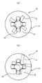
- (A), (b) is an outline of the tip blade portion with respect to the screw head when the tip blade portion of the conventional plus-type screwdriver bit is fitted in the bit fitting groove of the plus screw, respectively, indicating an inappropriate fitting state. It is explanatory drawing.
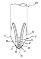
- FIG. 1 is a schematic side view of a tip blade portion
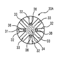
- FIG. 2 is a schematic end view of a tip surface of the tip blade portion.
- reference numeral 30 ⁇ / b> A is a tip blade protruding in a conical shape provided with a cross-shaped blade piece 32 that fits into a bit fitting groove of a screw formed of a cross groove formed on the top surface of the screw head. This is a plus-type driver bit including a portion 31.
- the plus-type driver bit 30A of the present embodiment configured as described above can be formed in the same manner as the conventional plus-type driver bit 10 as shown in FIGS. 7 (a) to 7 (c). That is, basically, the rod-shaped bit constituent material M is appropriately held by the chuck 2 of the machine tool (see FIG. 7A), and the bit constituent material M is rotated smoothly around its axis. A conical projection having a taper of a predetermined angle is cut at the tip of the bit constituent material M with a cutting tool 3 having a tapered cutting surface (see FIG. 7B).
- a milling cutter (rotary cutter) mounted on the shaft portion 4 orthogonal to the central axis of the bit constituent material M with respect to the tapered surface of the conical protrusion formed at the tip of the bit constituent material M.
- the recesses 33 extending in the axial direction of the bit constituent material M are cut to form the blade pieces 32 on both sides of the recesses (see FIG. 7C).
- a plus type The driver bit 30A can be manufactured.
- the front end surface of the plus-type driver bit 30A manufactured as described above is mirror-finished as a whole.
- a spherical surface dot-painted display portion. That is, as shown in FIG. 3, a diamond tool (not shown) or the like is used for the tip portion (broken line and hatched display portion) 35 formed in the shape of the conical protrusion of the tip blade portion 31 of the plus-type driver bit 30A. Use to finish the mirror finish.
- the tip portion 35 is polished and removed to form a spherical portion 34 by mirror finishing, and at the boundary portion between the spherical portion 34 and the cross-shaped blade piece 32, the bit axis is
- the step portion 36 dot coating display portion that forms the intersecting surfaces is provided.
- the driver bit 30 ⁇ / b> A includes a spherical portion 34 (dot coating display portion) formed by mirror finishing on the tip surface of the tip blade portion 31.
- the step portion 36 dot coating display portion
- the top surface of the screw head In the case of contact with the screw head, it is possible to prevent the occurrence of significant damage to the top surface of the screw head, even if it does not match due to misalignment of the blade and groove, misalignment of the center axis of the bit and screw, etc. It is possible to smoothly guide proper and quick fitting into the bit fitting groove at the tip, and it is possible to remarkably improve the efficiency and safety of the screw tightening operation.
- FIGS. 4 and 5 show another embodiment of the driver bit according to the present invention
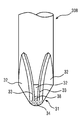
- FIG. 4 is a schematic side view of the tip blade portion
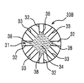
- FIG. 5 is a schematic plan view of the tip surface of the tip blade portion.
- reference numeral 30 ⁇ / b> B projects in a conical shape provided with a cross-shaped blade piece 32 that fits into a bit fitting groove of a screw formed of a cross groove formed on the top surface of the screw head.
- This is a plus-type screwdriver bit including a tip blade portion 31.
- the same cutting as that of the conventional plus-type driver bit 10 is performed in the same manner as in the first embodiment, as shown in FIGS.
- a plus-type driver bit 30B in which a cross-shaped blade 32 is basically formed at the tip of the bit constituent material M can be manufactured.
- the tip end surface of the plus-type driver bit 30B manufactured as described above is mirror-finished as a whole.
- a spherical surface dot-painted display portion. That is, as shown in FIG. 6, a diamond tool (not shown) is applied to the tip portion (broken line and hatched portion) 35 formed in the shape of a conical protrusion of the tip blade portion 31 of the plus-type driver bit 30B. Etc., and mirror finish processing.
- the tip portion 35 is polished and removed to form a spherical portion 34 by mirror finishing, and an integral mirror surface extending from the spherical portion 34 to the boundary portion with the cross-shaped blade piece 32.
- the curved surface 38 (dot coating display portion) is formed by finishing.
- the driver bit 30 ⁇ / b> B includes a spherical portion 34 (dot coating display portion) formed by mirror finishing on the tip surface of the tip blade portion 31.
- a spherical portion 34 dot coating display portion
- the curved surface 38 dot-coated display portion
- the present invention is not limited to the above-described embodiments, and the leading edge portion adapted to a screw having various bit fitting grooves having shapes other than the cross grooves.
- the present invention can be applied to a driver bit having a large number, and many design changes can be made without departing from the spirit of the present invention.
Landscapes
- Engineering & Computer Science (AREA)
- Mechanical Engineering (AREA)
- Hand Tools For Fitting Together And Separating, Or Other Hand Tools (AREA)
- Details Of Spanners, Wrenches, And Screw Drivers And Accessories (AREA)
- Milling Processes (AREA)
Abstract
ねじ頭部の頂部面に形成したねじのビット嵌合溝に対するドライバービット先端部の嵌合に際して、ねじ頭部の頂部面に対する損傷の発生を防止すると共に、前記ビット先端部のビット嵌合溝への適正な嵌合を迅速かつ円滑に達成し、ねじ締め作業の効率化と安全性を著しく高めることができるように構成したドライバービットを提供する。ねじ頭部の頂部面に設けた十字溝からなるねじのビット嵌合溝に嵌合する十字型の先端刃部を備えたドライバービット(30)において、前記先端刃部(31)の先端面を全体的に鏡面仕上げ加工により球面状(34)に形成した構成からなる。
Description
本発明は、ねじ締め作業において、ねじ頭部の頂部面に形成したねじのビット嵌合溝に対するドライバービット先端部の嵌合に際して、ねじ頭部の頂部面におけるビット嵌合溝周辺に対する損傷を防止すると共に、前記ビット先端部のビット嵌合溝への嵌合を迅速かつ円滑に達成し、ねじ締め作業の効率化と安全性を著しく高めることができるように構成したドライバービットに関するものである。
一般的に、ねじ頭部の頂部面に十字溝からなるビット嵌合溝を形成したプラスねじに適合するように、先端部に十字型の刃部を設けた構成からなるプラス型ドライバービットが、広く使用されている。通常、この種のプラス型ドライバービットは、ねじ頭部に形成されるビット嵌合溝が、十字状に形成した開口部からねじ頸部の中心部に指向して、逆円錐状に刻設した形状からなることから、このような形状に適合するように、十字型の刃部がビット先端部に指向して所定角度のテーパからなる先細り形状に構成されている。
このような構成からなるプラス型ドライバービットは、クロムバナジウム鋼、クロムモリブデン鋼等を棒状に圧延加工した鋼材をビット構成材料とし、このビット構成材料を使用して切削加工により成形される。
すなわち、前記プラス型ドライバービットの製造に際しては、図7の(a)に示すように、棒状のビット構成材料Mを、適宜工作機械のチャック2により保持し、このビット構成材料Mをその軸心回りに回転させながら、図7の(b)に示すように、平滑な切削面を有するテーパ切削用のバイト3により、ビット構成材料Mの先端部に所定角度のテーパからなる円錐状突起部11を切削加工する。
次に、図7の(c)に示すように、前記ビット構成材料Mの先端部に形成された円錐状突起部11のテーパ面に対して、ビット構成材料Mの中心軸線と直交する軸部4に装着されているフライス(回転式刃物)5により、ビット構成材料Mの軸線方向に延在する凹部13を切削して、前記凹部13の両側にそれぞれ刃部12を形成する。このようにして、前記ビット構成材料Mの軸線方向に延在する4つの凹部13を切削することにより、ビット構成材料Mの先端部(11)に十字型の刃部12を切削加工することにより、プラス型ドライバービット10を製造することができる。
このように製造された従来のプラス型ドライバービット10においては、図8の(a)、(b)に示すように、このドライバービット10に対応するねじ頭部21の頂部面22に十字溝からなるビット嵌合溝23を設けたプラスねじ20に適用してねじ締め作業を行う場合、最初に、前記ドライバービット10の先端刃部12を前記プラスねじ20のビット嵌合溝23に対して、手動操作等により所要の加速度をもって嵌合させる必要がある。この場合において、前記ドライバービット10の十字型の刃部12が、前記プラスねじ20の十字溝からなるビット嵌合溝23に対し、刃と溝の位置ずれ〔図8の(a)参照〕やビットとねじの中心軸のずれ〔図8の(b)参照〕等により適正に嵌合しないことから、前記十字型の刃部12の先端面のエッジ部分が、ビット嵌合溝23の十字溝の開口縁部ないしその周辺に当接して、ねじ頭部21の頂部面22を損傷してしまう難点がある。
また、前記ドライバービット10を、機械的操作により常に一定の動力により進退動作させて、自動供給されるねじとの嵌合を行い、自動的なねじ締め作業を行うように構成した自動ねじ締め装置において適用する場合には、前記のように、ドライバービット10とねじ20との結合に際して発生するねじ頭部21の頂部面22に対する損傷は、強大化されてより増大することとなり、適正なねじ締め作業ができなくなる難点がある。
すなわち、前述したような前記ドライバービット10と前記プラスねじ20との結合に際して発生するねじ頭部21の頂部面22に対する損傷は、所要の組立て製品ないし部品に対して適正なねじ締めを完了しても、組立て製品においては意匠的美観を損なうと共に、組立て部品においては周辺部品に対し悪影響を及ぼし、さらに損傷が大きい場合には、ドライバービット10による適正なねじ締めを行うことができなくなる難点がある。
しかるに、前述したプラス型ドライバービットとして、ドライバービットの先端部における十字頭部の強度を低下させることなく、カムアウト現象の発生を抑制できるようにした回転工具用ビットが提案されている(特許文献1参照)。
この特許文献1に記載されている回転工具用ビットは、ねじ頭に形成された十字溝に嵌合する四枚の羽部が対称に形成されている十字頭部を備え、同頭部の先端側に向かうに従い軸心側に傾斜する傾斜面が前記各羽部の外周縁部に形成されている回転工具用ビットにおいて、前記羽部の傾斜面に、同傾斜面の幅方向に渡る複数条の断面円弧状凹溝が、当該傾斜面の傾斜方向に沿って間隔をおいて列設され、かつこの凹溝間に前記傾斜面が残存されており、前記凹溝は、前記十字頭部を前記十字溝に嵌合させたときに当該十字溝の内部に位置する羽部の先端側の部分のみに配置されており、前記十字溝に対して前記ビットの先端部を回動させた際に、前記凹溝によって形成された前記各羽部のエッジ部分が前記十字溝の傾斜面に喰い込む構成としたものである。
この特許文献1に記載されている回転工具用ビットは、ねじ頭に形成された十字溝に嵌合する四枚の羽部が対称に形成されている十字頭部を備え、同頭部の先端側に向かうに従い軸心側に傾斜する傾斜面が前記各羽部の外周縁部に形成されている回転工具用ビットにおいて、前記羽部の傾斜面に、同傾斜面の幅方向に渡る複数条の断面円弧状凹溝が、当該傾斜面の傾斜方向に沿って間隔をおいて列設され、かつこの凹溝間に前記傾斜面が残存されており、前記凹溝は、前記十字頭部を前記十字溝に嵌合させたときに当該十字溝の内部に位置する羽部の先端側の部分のみに配置されており、前記十字溝に対して前記ビットの先端部を回動させた際に、前記凹溝によって形成された前記各羽部のエッジ部分が前記十字溝の傾斜面に喰い込む構成としたものである。
また、精密電子機器の組み立て等の磁気を嫌う環境での使用に適し、精密機械の組み立て等の錆を嫌う環境での使用に適し、かつ軽量で手の疲労や消費電力の少ないドライバーが提案されている(特許文献2参照)。
この特許文献2に記載されているドライバーは、本体軸部の先端にドライバー先端部を形成したドライバーであって、少なくともドライバー先端部がチタン又はチタン合金で形成した構成からなるものである。
この特許文献2に記載されているドライバーは、本体軸部の先端にドライバー先端部を形成したドライバーであって、少なくともドライバー先端部がチタン又はチタン合金で形成した構成からなるものである。
前記特許文献1および特許文献2に記載されているビットおよびドライバーは、それぞれねじのビット嵌合溝と嵌合する先端部の改善を提案しているが、いずれにおいても、ねじのビット嵌合溝に対するドライバービット先端部の嵌合に際して、ねじ頭部の頂部面に対する損傷の発生を防止すると共に、前記ビット先端部のビット嵌合溝への適正な嵌合を迅速かつ円滑に達成することは困難である。
そこで、本発明者は、種々検討を重ねた結果、ねじ頭部の頂部面に設けた十字溝からなるねじのビット嵌合溝に嵌合する十字型の先端刃部を備えたドライバービットにおいて、前記先端刃部の先端面を全体的に鏡面仕上げ加工により球面状に形成することにより、ねじのビット嵌合溝に対するドライバービット先端部の嵌合に際して、ねじ頭部の頂部面に対する損傷の発生を防止すると共に、前記ビット先端部のビット嵌合溝への嵌合を迅速かつ円滑に達成し、ねじ締め作業の効率化と安全性を著しく高めることができることを突き止めた。
従って、本発明の目的は、ねじ頭部の頂部面に形成したねじのビット嵌合溝に対するドライバービット先端部の嵌合に際して、ねじ頭部の頂部面に対する損傷の発生を防止すると共に、前記ビット先端部のビット嵌合溝への適正な嵌合を迅速かつ円滑に達成し、ねじ締め作業の効率化と安全性を著しく高めることができるように構成したドライバービットを提供することにある。
前記の目的を達成するため、本発明の請求項1に記載のドライバービットは、ねじ頭部の頂部面に設けた十字溝からなるねじのビット嵌合溝に嵌合する十字型の刃部を備えたドライバービットにおいて、
前記先端刃部の先端面を全体的に鏡面仕上げ加工により球面状に形成した構成からなることを特徴とする。
前記先端刃部の先端面を全体的に鏡面仕上げ加工により球面状に形成した構成からなることを特徴とする。
本発明の請求項2に記載のドライバービットは、前記先端刃部の鏡面仕上げ加工による球面状の部分と十字型の刃片との境界部分において、ビット軸に対して交差する面を形成する段部を設けた構成からなることを特徴とする。
本発明の請求項3に記載のドライバービットは、前記先端刃部の鏡面仕上げ加工による球面状の部分から十字型の刃片との境界部分に至るまで、一体的な鏡面仕上げ加工による球面および湾曲面とした構成からなることを特徴とする。
本発明の請求項1に記載のドライバービットによれば、ねじのビット嵌合溝に対するドライバービット先端部の嵌合に際して、ねじ頭部の頂部面に対する損傷の発生を防止すると共に、前記ビット先端部のビット嵌合溝への嵌合を迅速かつ円滑に達成し、ねじ締め作業の効率化と安全性を著しく高めることができる。すなわち、ドライバービットの先端刃部の先端面を鏡面仕上げ加工により球面状に形成したことにより、前記ドライバービットの先端刃部をねじのビット嵌合溝に対して所要の加速度をもって嵌合させる際に、ねじ頭部の頂部面に当接した場合において、刃と溝の位置ずれやビットとねじの中心軸のずれ等を生じたとしても、前記ねじ頭部の頂部面に対する顕著な損傷の発生を防止することができるばかりでなく、ビット先端部のビット嵌合溝への適正かつ迅速な嵌合を円滑に誘導することができ、ねじ締め作業の効率化と安全性に寄与する効果は極めて大きい。
本発明の請求項2に記載のドライバービットによれば、前記と同様にしてねじ頭部の頂部面に対する損傷の発生を防止し、ビット先端部のビット嵌合溝への適正な嵌合を迅速かつ円滑に達成することができると共に、特にビット軸に対して平行な垂直面を形成する段部を設けることによって、ねじ締め作業に際してのビット嵌合溝からのカムアウトを有効に防止することができる。
本発明の請求項3に記載のドライバービットによれば、前記と同様にしてねじ頭部の頂部面に対する損傷の発生を防止し、ビット先端部のビット嵌合溝への適正な嵌合を迅速かつ円滑に達成することができると共に、特に自動ねじ締め装置において適用することによって、ねじ締め作業の効率化と安全性を著しく高めることができる。
次に、本発明に係るドライバービットの実施例につき、添付図面を参照しながら以下詳細に説明する。
図1および図2は、本発明に係るドライバービットの一実施例を示すものであり、図1は先端刃部の概略側面図、図2は先端刃部の先端面の概略端面図である。図1および図2において、参照符号30Aはねじ頭部の頂部面に形成した十字溝からなるねじのビット嵌合溝に嵌合する十字型の刃片32を設けた円錐状に突出する先端刃部31を備えるプラス型ドライバービットである。
しかるに、このように構成される本実施例のプラス型ドライバービット30Aは、図7の(a)~(c)に示すように、従来のプラス型ドライバービット10と同様に成形することができる。すなわち、基本的には、棒状のビット構成材料Mを、適宜工作機械のチャック2により保持し〔図7の(a)参照〕、このビット構成材料Mをその軸心回りに回転させながら、平滑な切削面を有するテーパ切削用のバイト3により、ビット構成材料Mの先端部に所定角度のテーパからなる円錐状突起部を切削加工する〔図7の(b)参照〕。
次に、前記ビット構成材料Mの先端部に形成された円錐状突起部のテーパ面に対して、ビット構成材料Mの中心軸線と直交する軸部4に装着されているフライス(回転式刃物)5により、ビット構成材料Mの軸線方向に延在する凹部33を切削して、前記凹部の両側にそれぞれ刃片32を形成する〔図7の(c)参照〕。このようにして、前記ビット構成材料Mの軸線方向に延在する4つの凹部33を切削することにより、ビット構成材料Mの先端部に十字型の刃片32を切削加工することにより、プラス型ドライバービット30Aを製造することができる。
そこで、本実施例のドライバービット30Aにおいては、図3に示すように、前記のように製造されたプラス型ドライバービット30Aの先端刃部31に対して、その先端面を全体的に鏡面仕上げ加工により球面状(ドット塗り表示部分)に形成する。すなわち、図3に示すように、プラス型ドライバービット30Aの先端刃部31の円錐突起部状に形成された先端部分(破線およびハッチング表示部分)35に対して、ダイヤモンド工具(図示せず)等を使用して、鏡面仕上げ加工を施す。これにより、前記先端部分35を研磨除去して、鏡面仕上げ加工による球面状の部分34を構成すると共に、前記球面状の部分34と十字型の刃片32との境界部分において、ビット軸に対して交差する面を形成する段部36(ドット塗り表示部分)を設けた構成とする。
このような構成からなる本実施例に係るドライバービット30Aは、図1および図2に示すように、先端刃部31の先端面に鏡面仕上げ加工による球面状の部分34(ドット塗り表示部分)と段部36(ドット塗り表示部分)とを設けることにより、前記ドライバービット30Aの先端刃部31をねじのビット嵌合溝に対して所要の加速度をもって嵌合させるために、ねじ頭部の頂部面に当接する場合において、刃と溝の位置ずれやビットとねじの中心軸のずれ等により一致しないとしても、前記ねじ頭部の頂部面に対する顕著な損傷の発生を防止することができると共に、ビット先端部のビット嵌合溝への適正かつ迅速な嵌合を円滑に誘導することができ、ねじ締め作業の効率化と安全性を著しく高めることができる。
図4および図5は、本発明に係るドライバービットの別の実施例を示すものであり、図4は先端刃部の概略側面図、図5は先端刃部の先端面の概略平面図である。なお、説明の便宜上、前述した図1ないし図3に示す実施例1と同一の構成要素には、同一の参照符号を付して説明する。従って、図4および図5において、参照符号30Bはねじ頭部の頂部面に形成した十字溝からなるねじのビット嵌合溝に嵌合する十字型の刃片32を設けた円錐状に突出する先端刃部31を備えるプラス型ドライバービットである。
しかるに、本実施例のプラス型ドライバービット30Bにおいても、前記実施例1と全く同様にして、図7の(a)~(c)に示すように、従来のプラス型ドライバービット10と同様の切削加工によって、基本的にビット構成材料Mの先端部に十字型の刃片32を形成したプラス型ドライバービット30Bを製造することができる。
そこで、本実施例のドライバービット30Bにおいては、図6に示すように、前記のように製造されたプラス型ドライバービット30Bの先端刃部31に対して、その先端面を全体的に鏡面仕上げ加工により球面状(ドット塗り表示部分)に形成する。すなわち、図6に示すように、プラス型ドライバービット30Bの先端刃部31の円錐突起部状に形成された先端部分(破線およびハッチング表示した部分)35に対して、ダイヤモンド工具(図示せず)等を使用して、鏡面仕上げ加工を施す。これにより、前記先端部分35を研磨除去して、鏡面仕上げ加工による球面状の部分34を構成すると共に、前記球面状の部分34から十字型の刃片32との境界部分に至る一体的な鏡面仕上げ加工による湾曲面38(ドット塗り表示部分)を形成する構成とする。
このような構成からなる本実施例に係るドライバービット30Bは、図4および図5に示すように、先端刃部31の先端面に鏡面仕上げ加工による球面状の部分34(ドット塗り表示部分)と湾曲面38(ドット塗り表示部分)とを設けることにより、前記実施例1と全く同様に、ねじ頭部の頂部面に対する顕著な損傷の発生を防止することができると共に、ビット先端部のビット嵌合溝への適正かつ迅速な嵌合を円滑に誘導することができ、特に自動ねじ締め装置への適用に有効であり、ねじ締め作業の効率化と安全性に寄与する効果は極めて大きい。
以上、本発明の好適な実施例について説明したが、本発明は前述した実施例に限定されることなく、十字溝以外の形状からなる各種のビット嵌合溝を有するねじに適合する先端刃部を有するドライバービットに対しても応用することが可能であり、その他本発明の精神を逸脱しない範囲内において多くの設計変更を行うこともできる。
30A、30B プラス型ドライバービット
31 先端刃部
32 十字型の刃片
33 凹部
34 球面状の部分
35 研磨除去部分
36 段部
38 湾曲面
31 先端刃部
32 十字型の刃片
33 凹部
34 球面状の部分
35 研磨除去部分
36 段部
38 湾曲面
Claims (3)
- ねじ頭部の頂部面に設けた十字溝からなるねじのビット嵌合溝に嵌合する十字型の先端刃部を備えたドライバービットにおいて、
前記先端刃部の先端面を全体的に鏡面仕上げ加工により球面状に形成した構成からなることを特徴とするドライバービット。 - 前記先端刃部の鏡面仕上げ加工による球面状の部分と十字型の刃片との境界部分において、ビット軸に対して交差する面を形成する段部を設けた構成からなることを特徴とする請求項1記載のドライバービット。
- 前記先端刃部の鏡面仕上げ加工による球面状の部分から十字型の刃片との境界部分に至るまで、一体的な鏡面仕上げ加工による球面および湾曲面とした構成からなることを特徴とする請求項1記載のドライバービット。
Priority Applications (2)
| Application Number | Priority Date | Filing Date | Title |
|---|---|---|---|
| EP10844723.6A EP2529889B1 (en) | 2010-01-28 | 2010-12-20 | Screwdriver bit |
| US13/522,921 US20120285301A1 (en) | 2010-01-28 | 2010-12-20 | Screwdriver Bit |
Applications Claiming Priority (2)
| Application Number | Priority Date | Filing Date | Title |
|---|---|---|---|
| JP2010-016636 | 2010-01-28 | ||
| JP2010016636A JP5419733B2 (ja) | 2010-01-28 | 2010-01-28 | ドライバービット |
Publications (1)
| Publication Number | Publication Date |
|---|---|
| WO2011092969A1 true WO2011092969A1 (ja) | 2011-08-04 |
Family
ID=44318968
Family Applications (1)
| Application Number | Title | Priority Date | Filing Date |
|---|---|---|---|
| PCT/JP2010/072863 Ceased WO2011092969A1 (ja) | 2010-01-28 | 2010-12-20 | ドライバービット |
Country Status (5)
| Country | Link |
|---|---|
| US (1) | US20120285301A1 (ja) |
| EP (1) | EP2529889B1 (ja) |
| JP (1) | JP5419733B2 (ja) |
| CN (1) | CN102139478B (ja) |
| WO (1) | WO2011092969A1 (ja) |
Cited By (1)
| Publication number | Priority date | Publication date | Assignee | Title |
|---|---|---|---|---|
| TWI701108B (zh) * | 2017-03-23 | 2020-08-11 | 美商葛利普控股公司 | 多夾持點套筒起子頭 |
Families Citing this family (8)
| Publication number | Priority date | Publication date | Assignee | Title |
|---|---|---|---|---|
| US9067307B2 (en) * | 2012-12-05 | 2015-06-30 | Burton Kozak | Hexa-lobed head bit |
| JP5497957B1 (ja) * | 2013-10-03 | 2014-05-21 | 和美 湯山 | ショックドライバー用のビット |
| KR101507492B1 (ko) | 2014-11-13 | 2015-03-30 | 김상현 | 십자형 드라이버 비트 및 십자형 드라이버 비트의 제조방법 |
| US11478907B2 (en) | 2016-11-30 | 2022-10-25 | Hangzhou Great Star Tools Co., Ltd. | Screwdriver head and method for manufacturing the same |
| US11059162B2 (en) | 2017-05-17 | 2021-07-13 | Milwaukee Electric Tool Corporation | Screwdriver |
| USD855433S1 (en) | 2017-08-09 | 2019-08-06 | Milwaukee Electric Tool Corporation | Screwdriver |
| TWI784842B (zh) * | 2021-12-15 | 2022-11-21 | 洪昭敏 | 起子頭結構 |
| TWI875535B (zh) * | 2024-03-21 | 2025-03-01 | 洪昭敏 | 起子頭結構 |
Citations (5)
| Publication number | Priority date | Publication date | Assignee | Title |
|---|---|---|---|---|
| JPH09508323A (ja) * | 1994-01-26 | 1997-08-26 | ヴァーモント・アメリカン・コーポレーション | 動力式ねじ回しと共に使用されるインサート・ビット |
| JP2000167776A (ja) | 1998-09-30 | 2000-06-20 | Vessel Kogyo:Kk | 回転工具用ビットとその製造方法及びドライバ― |
| JP2001179643A (ja) | 1999-12-27 | 2001-07-03 | Tookoma Kk | ドライバーおよびドライバー用線材 |
| JP2007002880A (ja) * | 2005-06-21 | 2007-01-11 | Union Seimitsu:Kk | 十字穴付ねじ |
| JP2009502543A (ja) * | 2005-08-03 | 2009-01-29 | シンセス・ゲゼルシヤフト・ミツト・ベシユレンクテル・ハフツング | ねじを保持するねじ回し |
Family Cites Families (16)
| Publication number | Priority date | Publication date | Assignee | Title |
|---|---|---|---|---|
| US2182568A (en) * | 1937-04-15 | 1939-12-05 | Illinois Tool Works | Screw |
| US2216381A (en) * | 1939-08-01 | 1940-10-01 | W H Holmes | Screw |
| US2537029A (en) * | 1946-08-06 | 1951-01-09 | Phillips Screw Co | Method for manufacturing screw drivers |
| GB673303A (en) * | 1950-07-12 | 1952-06-04 | Guest Keen & Nettlefords Midla | Improvements in or relating to screw drivers and their manufacture |
| US2673359A (en) * | 1951-01-11 | 1954-03-30 | Domnic V Stellin | Tool for forming recesses and sockets of high torque strength |
| BE539857A (ja) * | 1954-08-30 | |||
| US3295572A (en) * | 1959-05-18 | 1967-01-03 | Hi Shear Corp | Screw and screw driver coupling |
| US3207196A (en) * | 1963-06-24 | 1965-09-21 | Gardner Denver Co | Countersinking tool |
| US4590825A (en) * | 1983-05-06 | 1986-05-27 | John Vaughn | High torque fastener and driving tool |
| DE4241005A1 (de) * | 1992-12-05 | 1994-06-09 | Schmidt Ulrich Ush Schraubwerk | Werkzeug-Einsatzstück |
| US6128983A (en) * | 1999-01-06 | 2000-10-10 | Arnn; Edward T. | Drive tool for fasteners |
| US6176161B1 (en) * | 1999-10-28 | 2001-01-23 | Jung-Sheng Huang | Damaged screw removing screwdriver |
| CN2392025Y (zh) * | 1999-11-02 | 2000-08-16 | 张琦银 | 防盗螺栓紧固组件及其专用工具 |
| JP4205990B2 (ja) * | 2003-05-30 | 2009-01-07 | 日東精工株式会社 | 駆動穴付きねじ及びドライバビット |
| US8739660B2 (en) * | 2006-04-24 | 2014-06-03 | Ttapdrive As | Screw head and tool for use therewith |
| US20080092699A1 (en) * | 2006-10-24 | 2008-04-24 | Surowiecki Matt F | Wallboard screw with bi-tapered socket for receiving a bi-tapered screw driver tip |
-
2010
- 2010-01-28 JP JP2010016636A patent/JP5419733B2/ja active Active
- 2010-12-20 EP EP10844723.6A patent/EP2529889B1/en active Active
- 2010-12-20 US US13/522,921 patent/US20120285301A1/en not_active Abandoned
- 2010-12-20 WO PCT/JP2010/072863 patent/WO2011092969A1/ja not_active Ceased
-
2011
- 2011-01-19 CN CN201110021602.1A patent/CN102139478B/zh active Active
Patent Citations (5)
| Publication number | Priority date | Publication date | Assignee | Title |
|---|---|---|---|---|
| JPH09508323A (ja) * | 1994-01-26 | 1997-08-26 | ヴァーモント・アメリカン・コーポレーション | 動力式ねじ回しと共に使用されるインサート・ビット |
| JP2000167776A (ja) | 1998-09-30 | 2000-06-20 | Vessel Kogyo:Kk | 回転工具用ビットとその製造方法及びドライバ― |
| JP2001179643A (ja) | 1999-12-27 | 2001-07-03 | Tookoma Kk | ドライバーおよびドライバー用線材 |
| JP2007002880A (ja) * | 2005-06-21 | 2007-01-11 | Union Seimitsu:Kk | 十字穴付ねじ |
| JP2009502543A (ja) * | 2005-08-03 | 2009-01-29 | シンセス・ゲゼルシヤフト・ミツト・ベシユレンクテル・ハフツング | ねじを保持するねじ回し |
Cited By (1)
| Publication number | Priority date | Publication date | Assignee | Title |
|---|---|---|---|---|
| TWI701108B (zh) * | 2017-03-23 | 2020-08-11 | 美商葛利普控股公司 | 多夾持點套筒起子頭 |
Also Published As
| Publication number | Publication date |
|---|---|
| JP5419733B2 (ja) | 2014-02-19 |
| JP2011152625A (ja) | 2011-08-11 |
| CN102139478A (zh) | 2011-08-03 |
| EP2529889B1 (en) | 2019-07-17 |
| EP2529889A4 (en) | 2017-05-03 |
| EP2529889A1 (en) | 2012-12-05 |
| CN102139478B (zh) | 2014-12-03 |
| US20120285301A1 (en) | 2012-11-15 |
Similar Documents
| Publication | Publication Date | Title |
|---|---|---|
| JP5419733B2 (ja) | ドライバービット | |
| US20180154460A1 (en) | Tapered end mill and cutting head | |
| EP3646976B1 (en) | Ball end mill | |
| WO2012002267A1 (ja) | インサートおよび切削工具、並びにそれらを用いた切削加工物の製造方法 | |
| JP6971545B2 (ja) | 回転可能な切削工具と当該回転可能な切削工具のためのレンチ | |
| US20180318941A1 (en) | Indexable mill | |
| JP4677722B2 (ja) | 3枚刃ボールエンドミル | |
| CN103962616B (zh) | 一种用于加工复杂曲面的正交螺旋形切削刃椭球头铣刀 | |
| JP6027700B1 (ja) | エンドミルの再利用方法 | |
| KR20170135964A (ko) | 가공물 및 기계가공에 있어서의 그 응용물 | |
| JP2017030091A (ja) | 切削ヘッドおよびヘッド交換式切削工具 | |
| JP5780188B2 (ja) | 切削部材のクランプ機構及びこれを用いた刃部交換式切削工具 | |
| JPH10263914A (ja) | ボールエンドミル | |
| JP2007075993A (ja) | ラジアスカッタ、特にボールカッタまたは環状カッタ | |
| JP2013018085A (ja) | 突起型前案内部を有するブローチ工具 | |
| JP2007245338A (ja) | ミリングカッタ | |
| CN206382602U (zh) | 钻孔刀具 | |
| KR101555305B1 (ko) | 회전 절삭 공구 및 그 제조 방법 | |
| JP3113765U (ja) | 道具 | |
| JP2005319538A (ja) | ボールエンドミル | |
| JP4741646B2 (ja) | スローアウェイエンドミルおよびその製造方法 | |
| JP5688857B2 (ja) | 下削り用チェザー | |
| JP2005186179A (ja) | ブローチ工具 | |
| JP2010270857A (ja) | 等速自在継手の内輪およびその加工方法 | |
| JPH11197917A (ja) | チャック用交換式生爪 |
Legal Events
| Date | Code | Title | Description |
|---|---|---|---|
| 121 | Ep: the epo has been informed by wipo that ep was designated in this application |
Ref document number: 10844723 Country of ref document: EP Kind code of ref document: A1 |
|
| WWE | Wipo information: entry into national phase |
Ref document number: 2010844723 Country of ref document: EP |
|
| WWE | Wipo information: entry into national phase |
Ref document number: 13522921 Country of ref document: US |
|
| NENP | Non-entry into the national phase |
Ref country code: DE |