WO2011093053A1 - 流体機械 - Google Patents
流体機械 Download PDFInfo
- Publication number
- WO2011093053A1 WO2011093053A1 PCT/JP2011/000368 JP2011000368W WO2011093053A1 WO 2011093053 A1 WO2011093053 A1 WO 2011093053A1 JP 2011000368 W JP2011000368 W JP 2011000368W WO 2011093053 A1 WO2011093053 A1 WO 2011093053A1
- Authority
- WO
- WIPO (PCT)
- Prior art keywords
- fluid machine
- shell
- sealed container
- welded
- welding
- Prior art date
- Legal status (The legal status is an assumption and is not a legal conclusion. Google has not performed a legal analysis and makes no representation as to the accuracy of the status listed.)
- Ceased
Links
Images




Classifications
-
- F—MECHANICAL ENGINEERING; LIGHTING; HEATING; WEAPONS; BLASTING
- F04—POSITIVE - DISPLACEMENT MACHINES FOR LIQUIDS; PUMPS FOR LIQUIDS OR ELASTIC FLUIDS
- F04B—POSITIVE-DISPLACEMENT MACHINES FOR LIQUIDS; PUMPS
- F04B39/00—Component parts, details, or accessories, of pumps or pumping systems specially adapted for elastic fluids, not otherwise provided for in, or of interest apart from, groups F04B25/00 - F04B37/00
- F04B39/12—Casings; Cylinders; Cylinder heads; Fluid connections
-
- F—MECHANICAL ENGINEERING; LIGHTING; HEATING; WEAPONS; BLASTING
- F04—POSITIVE - DISPLACEMENT MACHINES FOR LIQUIDS; PUMPS FOR LIQUIDS OR ELASTIC FLUIDS
- F04B—POSITIVE-DISPLACEMENT MACHINES FOR LIQUIDS; PUMPS
- F04B39/00—Component parts, details, or accessories, of pumps or pumping systems specially adapted for elastic fluids, not otherwise provided for in, or of interest apart from, groups F04B25/00 - F04B37/00
- F04B39/12—Casings; Cylinders; Cylinder heads; Fluid connections
- F04B39/121—Casings
-
- B—PERFORMING OPERATIONS; TRANSPORTING
- B23—MACHINE TOOLS; METAL-WORKING NOT OTHERWISE PROVIDED FOR
- B23K—SOLDERING OR UNSOLDERING; WELDING; CLADDING OR PLATING BY SOLDERING OR WELDING; CUTTING BY APPLYING HEAT LOCALLY, e.g. FLAME CUTTING; WORKING BY LASER BEAM
- B23K33/00—Specially-profiled edge portions of workpieces for making soldering or welding connections; Filling the seams formed thereby
-
- B—PERFORMING OPERATIONS; TRANSPORTING
- B23—MACHINE TOOLS; METAL-WORKING NOT OTHERWISE PROVIDED FOR
- B23K—SOLDERING OR UNSOLDERING; WELDING; CLADDING OR PLATING BY SOLDERING OR WELDING; CUTTING BY APPLYING HEAT LOCALLY, e.g. FLAME CUTTING; WORKING BY LASER BEAM
- B23K33/00—Specially-profiled edge portions of workpieces for making soldering or welding connections; Filling the seams formed thereby
- B23K33/004—Filling of continuous seams
- B23K33/006—Filling of continuous seams for cylindrical workpieces
-
- B—PERFORMING OPERATIONS; TRANSPORTING
- B23—MACHINE TOOLS; METAL-WORKING NOT OTHERWISE PROVIDED FOR
- B23K—SOLDERING OR UNSOLDERING; WELDING; CLADDING OR PLATING BY SOLDERING OR WELDING; CUTTING BY APPLYING HEAT LOCALLY, e.g. FLAME CUTTING; WORKING BY LASER BEAM
- B23K9/00—Arc welding or cutting
-
- B—PERFORMING OPERATIONS; TRANSPORTING
- B23—MACHINE TOOLS; METAL-WORKING NOT OTHERWISE PROVIDED FOR
- B23K—SOLDERING OR UNSOLDERING; WELDING; CLADDING OR PLATING BY SOLDERING OR WELDING; CUTTING BY APPLYING HEAT LOCALLY, e.g. FLAME CUTTING; WORKING BY LASER BEAM
- B23K9/00—Arc welding or cutting
- B23K9/02—Seam welding; Backing means; Inserts
- B23K9/028—Seam welding; Backing means; Inserts for curved planar seams
- B23K9/0282—Seam welding; Backing means; Inserts for curved planar seams for welding tube sections
- B23K9/0286—Seam welding; Backing means; Inserts for curved planar seams for welding tube sections with an electrode moving around the fixed tube during the welding operation
-
- B—PERFORMING OPERATIONS; TRANSPORTING
- B23—MACHINE TOOLS; METAL-WORKING NOT OTHERWISE PROVIDED FOR
- B23K—SOLDERING OR UNSOLDERING; WELDING; CLADDING OR PLATING BY SOLDERING OR WELDING; CUTTING BY APPLYING HEAT LOCALLY, e.g. FLAME CUTTING; WORKING BY LASER BEAM
- B23K9/00—Arc welding or cutting
- B23K9/16—Arc welding or cutting making use of shielding gas
- B23K9/164—Arc welding or cutting making use of shielding gas making use of a moving fluid
-
- B—PERFORMING OPERATIONS; TRANSPORTING
- B23—MACHINE TOOLS; METAL-WORKING NOT OTHERWISE PROVIDED FOR
- B23K—SOLDERING OR UNSOLDERING; WELDING; CLADDING OR PLATING BY SOLDERING OR WELDING; CUTTING BY APPLYING HEAT LOCALLY, e.g. FLAME CUTTING; WORKING BY LASER BEAM
- B23K9/00—Arc welding or cutting
- B23K9/16—Arc welding or cutting making use of shielding gas
- B23K9/173—Arc welding or cutting making use of shielding gas and of a consumable electrode
-
- F—MECHANICAL ENGINEERING; LIGHTING; HEATING; WEAPONS; BLASTING
- F04—POSITIVE - DISPLACEMENT MACHINES FOR LIQUIDS; PUMPS FOR LIQUIDS OR ELASTIC FLUIDS
- F04B—POSITIVE-DISPLACEMENT MACHINES FOR LIQUIDS; PUMPS
- F04B39/00—Component parts, details, or accessories, of pumps or pumping systems specially adapted for elastic fluids, not otherwise provided for in, or of interest apart from, groups F04B25/00 - F04B37/00
- F04B39/14—Provisions for readily assembling or disassembling
-
- B—PERFORMING OPERATIONS; TRANSPORTING
- B23—MACHINE TOOLS; METAL-WORKING NOT OTHERWISE PROVIDED FOR
- B23K—SOLDERING OR UNSOLDERING; WELDING; CLADDING OR PLATING BY SOLDERING OR WELDING; CUTTING BY APPLYING HEAT LOCALLY, e.g. FLAME CUTTING; WORKING BY LASER BEAM
- B23K2101/00—Articles made by soldering, welding or cutting
- B23K2101/04—Tubular or hollow articles
- B23K2101/12—Vessels
-
- F—MECHANICAL ENGINEERING; LIGHTING; HEATING; WEAPONS; BLASTING
- F01—MACHINES OR ENGINES IN GENERAL; ENGINE PLANTS IN GENERAL; STEAM ENGINES
- F01C—ROTARY-PISTON OR OSCILLATING-PISTON MACHINES OR ENGINES
- F01C19/00—Sealing arrangements in rotary-piston machines or engines
- F01C19/005—Structure and composition of sealing elements such as sealing strips, sealing rings and the like; Coating of these elements
-
- F—MECHANICAL ENGINEERING; LIGHTING; HEATING; WEAPONS; BLASTING
- F04—POSITIVE - DISPLACEMENT MACHINES FOR LIQUIDS; PUMPS FOR LIQUIDS OR ELASTIC FLUIDS
- F04C—ROTARY-PISTON, OR OSCILLATING-PISTON, POSITIVE-DISPLACEMENT MACHINES FOR LIQUIDS; ROTARY-PISTON, OR OSCILLATING-PISTON, POSITIVE-DISPLACEMENT PUMPS
- F04C2230/00—Manufacture
- F04C2230/20—Manufacture essentially without removing material
- F04C2230/23—Manufacture essentially without removing material by permanently joining parts together
- F04C2230/231—Manufacture essentially without removing material by permanently joining parts together by welding
-
- F—MECHANICAL ENGINEERING; LIGHTING; HEATING; WEAPONS; BLASTING
- F04—POSITIVE - DISPLACEMENT MACHINES FOR LIQUIDS; PUMPS FOR LIQUIDS OR ELASTIC FLUIDS
- F04C—ROTARY-PISTON, OR OSCILLATING-PISTON, POSITIVE-DISPLACEMENT MACHINES FOR LIQUIDS; ROTARY-PISTON, OR OSCILLATING-PISTON, POSITIVE-DISPLACEMENT PUMPS
- F04C2240/00—Components
- F04C2240/30—Casings or housings
-
- F—MECHANICAL ENGINEERING; LIGHTING; HEATING; WEAPONS; BLASTING
- F04—POSITIVE - DISPLACEMENT MACHINES FOR LIQUIDS; PUMPS FOR LIQUIDS OR ELASTIC FLUIDS
- F04C—ROTARY-PISTON, OR OSCILLATING-PISTON, POSITIVE-DISPLACEMENT MACHINES FOR LIQUIDS; ROTARY-PISTON, OR OSCILLATING-PISTON, POSITIVE-DISPLACEMENT PUMPS
- F04C23/00—Combinations of two or more pumps, each being of rotary-piston or oscillating-piston type, specially adapted for elastic fluids; Pumping installations specially adapted for elastic fluids; Multi-stage pumps specially adapted for elastic fluids
- F04C23/008—Hermetic pumps
-
- Y—GENERAL TAGGING OF NEW TECHNOLOGICAL DEVELOPMENTS; GENERAL TAGGING OF CROSS-SECTIONAL TECHNOLOGIES SPANNING OVER SEVERAL SECTIONS OF THE IPC; TECHNICAL SUBJECTS COVERED BY FORMER USPC CROSS-REFERENCE ART COLLECTIONS [XRACs] AND DIGESTS
- Y10—TECHNICAL SUBJECTS COVERED BY FORMER USPC
- Y10S—TECHNICAL SUBJECTS COVERED BY FORMER USPC CROSS-REFERENCE ART COLLECTIONS [XRACs] AND DIGESTS
- Y10S418/00—Rotary expansible chamber devices
- Y10S418/01—Non-working fluid separation
Definitions
- the present invention relates to a fluid machine, and more particularly to a fluid machine suitable for a hermetic reciprocating compressor that compresses a carbon dioxide refrigerant.
- a hermetic compressor As this type of fluid machine, a hermetic compressor is known in which an electric motor and a compression mechanism that compresses a refrigerant by a driving force transmitted from the electric motor are housed in a hermetic container.
- the hermetic container described in Patent Document 1 is composed of three members: a cylindrical center shell, and a cup-shaped top shell and a bottom shell that are welded to both opening ends of the center shell. The molten metal is welded and joined while applying an acting force in the welding progress direction.
- the sealed container is composed of three members, the number of welding locations is at least two and requires assembly man-hours for the sealed container. There is a problem that increases. Therefore, it is considered that if the sealed container is composed of only two members, a top shell and a bottom shell, the number of welding points is reduced, the number of assembling steps for the sealed container can be reduced, and the manufacturing cost of the sealed container can be reduced.
- the above prior art welding method is a method premised on the case where a cup-shaped top shell and a bottom shell are welded to a cylindrical center shell, and when the sealed container is configured with a cup-shaped two-body shell structure, Due to the absence of the center shell, it is impossible to effectively release the welding heat, it is difficult to tolerate the thermal deformation of each shell due to the welding heat, and a crack is generated in the molten part of each shell after welding. For this reason, the throat thickness of the welded part cannot be secured sufficiently, or an unwelded part of the welded part occurs, and stress concentration due to force or moment occurs at this part, which may cause fatigue failure of the sealed container. is there.
- the present invention has been made based on the above-mentioned circumstances, and an object of the present invention is to provide a fluid machine that can increase the welding strength and improve the reliability while reducing the manufacturing cost.
- a fluid machine is a fluid machine in which a drive unit and a driven unit to which the driving force of the drive unit is transmitted are contained in a sealed container.
- the first shell that covers the drive unit side and the second shell that is joined to the first shell and covers the driven unit side are formed by abutting the respective opening end portions.
- the groove portion is welded all around to form a welded portion, and the welded portion is spaced apart from the seal portion that is in contact with each other at each opening end portion with a predetermined space ( Claim 1).
- the space is formed by a root edge portion that forms a groove portion, a recessed portion recessed inward of each opening end portion, and a seal portion (claim 2).
- the seal portions are brought into contact with each other at an inclined surface inclined with respect to the abutting direction of the opening end portions (claim 3). Further, the seal portions are in contact with each other on a plurality of different surfaces (claim 4).
- the root portion which is the boundary between each concave portion and the welded portion, is formed such that the wall surface of each concave portion and the inner end portion of the welded portion form an acute angle. Furthermore, the space has a substantially heart shape in sectional view. Further, the pressure of the working fluid sucked into the driven unit and discharged from the driven unit acts in the sealed container, and the working fluid is a carbon dioxide refrigerant (Claim 7).
- the sealed container can be assembled in one man-hour, and the manufacturing cost of the sealed container and the compressor can be reduced.
- the stress concentration on the welded part is alleviated, so the occurrence of cracks is suppressed, and further, spatter and sparks scattered during welding are prevented from entering the sealed container, and The throat thickness of the welded portion can be ensured and the welding strength can be increased while preventing the welded portion from reaching the sealed container, so that the reliability of the fluid machine can be improved.
- the seal portions are brought into contact with each other on the inclined surface, assembly errors in both directions of the butting direction of the shells and the radial direction of the shells, which are perpendicular to each other, are allowable.
- the shells can be easily positioned and assembled without strictly managing the dimensional accuracy of the shells.
- Spatters and sparks during welding tend to scatter toward the radial center of each shell, but spatters and sparks during welding penetrate into the sealed container by contacting the seals with each other on the slope. This can be effectively prevented.
- spatter and sparks during welding tend to scatter toward the center in the radial direction of each shell, but by bringing each seal portion into contact with each other on a plurality of different surfaces, Therefore, it is possible to more reliably prevent spatter and sparks during welding from entering the sealed container.
- the root portion is formed such that the wall surface and the inner end portion of each recess form an acute angle, so that the wall surface of each recess after welding and the weld portion are at a gentle angle. Since it continues smoothly, stress concentration and, therefore, cracks caused by the stress are hardly generated at the boundary between the welded portion and the base material that is each shell, and the weld strength of the welded portion can be further increased.
- the space has a substantially heart shape in cross section, so that the wall surface of each recess after welding and the welded portion are smoothly continuous at a loose angle, and the inner end of the welded portion Since each seal part can be separated as much as possible, the weld strength of the welded part can be increased while effectively preventing spatter and sparks from entering the sealed container.
- the pressure of the working fluid discharged from the driven unit is increased to a supercritical state, and the pressure acting on the sealed container may be increased. Therefore, for safety reasons, it is usually unavoidable to make the sealed container thick, and a high weld strength is required for the welded portion between the shells.
- the above configuration is preferable because the weld strength of the welded portion can be increased, and the reliability of the fluid machine can be improved.
- FIG. 5 is another modification of the weld joint of FIG. 4.
- FIG. 5 is another modification of the weld joint of FIG. 4.
- the compressor 1 is a hermetic reciprocating compressor, and is categorized in detail as a positive displacement compressor called a reciprocating compressor or a piston compressor.
- a configuration of a refrigeration cycle (not shown) incorporated in a vending machine. Used as equipment.
- the refrigeration cycle includes a path through which a refrigerant as a working fluid of the compressor 1 circulates.
- a carbon dioxide refrigerant that is a non-flammable natural refrigerant is used as the refrigerant.
- the compressor 1 includes an airtight container 2, and an electric motor (drive unit) 4 and a compression mechanism (driven unit) to which the driving force of the electric motor 4 is transmitted are enclosed in the airtight container 2. 6) is housed.
- the electric motor 4 includes a stator 8 that generates a magnetic field by power feeding and a rotor 10 that rotates by the magnetic field generated by the stator 8.
- the rotor 10 is disposed coaxially inside the stator 8, and will be described later.
- the main shaft portion 24 is fixed by shrinkage fitting. Electric power is supplied to the stator 8 from the outside of the compressor 1 through an electrical component 12 fixed to the sealed container 2 and a lead wire (not shown).
- the compression mechanism 6 includes a crankshaft 14, a cylinder block 16, a piston 18, a connecting rod 20, and the like.
- the crankshaft 14 includes an eccentric shaft portion 22 and a main shaft portion 24.
- a cylinder bore 26 is formed integrally with the cylinder block 16, and a cylinder gasket 28, a later-described suction valve 50, and a valve plate 30 are sequentially arranged from the cylinder block 16 side so as to close the opening of the cylinder bore 26.
- the head gasket 32 and the cylinder head 34 are pressed and fixed by bolts.
- the stator 8 is bolted to the cylinder block 16 via a frame 36, and the frame 36 is fixed to the sealed container 2.
- the electric motor 4 and the compression mechanism 6 are supported by a pedestal portion 38 below the frame 36, and the frame 36 is fixed to the sealed container 2 by the pedestal portion 38.
- the bearing 42 of the main shaft portion 24 is disposed on the inner peripheral surface 40a, and the thrust trace (bearing) that receives the thrust load of the rotor 10 on the upper end surface 40b of the cylindrical portion 40.
- a bearing 44 such as a thrust washer is disposed.
- the valve plate 30 includes a refrigerant suction hole 46 and a discharge hole 48, both of which are opened and closed by a suction valve 50 and a discharge valve 52, which are reed valves, respectively.
- the cylinder head 34 includes a refrigerant suction chamber 54 and a discharge chamber 56.
- the discharge valve 52 When the discharge valve 52 is opened in the compression stroke of the piston 18, the discharge chamber 56 communicates with the cylinder bore 26 through the discharge hole 48.
- the intake valve 50 is opened during the intake stroke of the piston 18, the intake chamber 54 communicates with the cylinder bore 26 via the intake hole 46.
- a suction pipe 58 and a discharge pipe 60 are fixed to the sealed container 2, and one ends of the suction and discharge pipes 58 and 60 are connected to a suction chamber 54 and a discharge chamber 56 of the cylinder head 34, respectively.
- the other ends of the suction and discharge pipes 58 and 60 are connected to a refrigeration cycle via a suction muffler and a discharge muffler (not shown), and these mufflers reduce the pulsation and noise of the refrigerant flowing between the compressor 1 and the refrigeration cycle. ing.
- the connecting rod 20 is provided with a large end 62 to which the eccentric shaft portion 22 of the crankshaft 14 is rotatably connected at one end, and a small end 64 to which the piston 18 is reciprocally connected at the other end. It has been.
- the small end portion 64 is connected to the piston 18 by a piston pin 66, and the piston pin 66 is secured to the piston 18 by a fixing pin 68.
- the connecting rod 20 swings in conjunction with the eccentric rotation of the eccentric shaft portion 22 with the piston pin 66 as a fulcrum, and the piston 18 interlocks with the swinging motion of the connecting rod 20. It reciprocates in the cylinder bore 26.
- the discharge pressure of the refrigerant mainly acts in the sealed container 2, and a small amount of lubricating oil for lubricating the sliding portions of the electric motor 4 and the compression mechanism 6, such as the bearings 42 and 44, in the inner bottom portion 2 a of the sealed container 2.
- an oil passage (lubricating mechanism) 70 is drilled from the substantially axial position of the lower end surface 22 a of the eccentric shaft portion 22 to the middle of the main shaft portion 24.
- An upper portion of the oil passage 70 is opened from the outer peripheral surface 24 a of the main shaft portion 24, and an oil pipe (lubricating mechanism) 72 is connected to the lower portion of the oil passage 70.
- the oil pipe 72 has an inclined portion 74 which is inclined from the substantially axial center of the eccentric shaft portion 22 toward the axial center of the main shaft portion 24 on the distal end side. It extends to the oil reservoir 76 having a concave shape in sectional view formed in the inner bottom 2a.
- the oil sump portion 76 is formed to have a size and depth that allow a small amount of lubricating oil, for example, about 200 cc, to be stored so that the oil level is higher than the tip position of the oil pipe 74.
- a centrifugal force acts on the lubricating oil in the inclined portion 74 in the oil pipe 72 in an obliquely upward outward direction. Is pumped from the oil reservoir 76 to the oil passage 74.
- the operation and action of the compressor 1 will be described.
- the rotor 10 fixed to the main shaft portion 24 is rotated by supplying power to the stator 8, and consequently the crankshaft 14 is rotated, and the piston 18 reciprocates in the cylinder bore 26 via the connecting rod 20.
- the reciprocating motion of the piston 18 causes the refrigerant to be sucked into the cylinder bore 26 from the refrigeration cycle, and the refrigerant is compressed by the cylinder bore 26 and further discharged to the refrigeration cycle.
- the piston 18 operates in the direction of decreasing the volume of the cylinder bore 26 and the refrigerant in the cylinder bore 26 is compressed and the pressure in the cylinder bore 26 exceeds the discharge pressure of the refrigerant, the pressure in the cylinder bore 26 and the discharge chamber 56 are increased.
- the discharge valve 52 opens due to the difference from the internal pressure. The compressed refrigerant is guided to the discharge chamber 56 via the discharge hole 48 and discharged to the refrigeration cycle via the discharge pipe 60.
- the pressure in the cylinder bore 26 decreases.
- the discharge valve 52 closes according to the difference between the pressure in the cylinder bore 26 and the pressure in the discharge chamber 56.
- the suction valve 50 opens according to the difference between the pressure in the cylinder bore 26 and the pressure in the suction chamber 54. The refrigerant in the refrigeration cycle is guided to the suction chamber 54 through the suction pipe 58 and is sucked into the cylinder bore 26 through the suction hole 46.
- the lubricating oil pumped up from the oil reservoir 76 to the oil passage 70 in accordance with the operation of the compressor 1 described above flows out from the oil passage 70, flows down to the eccentric shaft portion 22 side, and lubricates the vicinity of the large end portion 62. Further, it is scattered toward the piston 18 by centrifugal force, and the vicinity of the skirt portion 18a of the piston 18 is lubricated.
- a part of the lubricating oil flowing out from the oil passage 70 rises along an outer peripheral groove (not shown) formed in the crankshaft 14 by centrifugal force, and forms an oil film between the crankshaft 14 and the frame 36. Then, the bearing 42 is lubricated and moved to the upper end side of the crankshaft 14. The lubricating oil reaches the upper end surface 40b of the cylindrical portion 40 and lubricates the bearing 44, and then flows down to the oil sump portion 76 by gravity.
- the lubricating oil that cannot pass through the bearing 44 rises as it is up the inner wall surface 10a of the rotor 10 to the upper end of the rotor 10, is scattered by the centrifugal force due to the rotation of the rotor 10, cools the stator 8, and then To flow down to the oil sump 76.
- the sealed container 2 includes a top shell (first shell) 78 that covers the electric motor 4 side, and a bottom shell (second shell) 80 that covers the compression mechanism 6 side.
- the shell structure is composed of two shells. Since the crankshaft 14 and the connecting rod 20 are positioned so as to be substantially orthogonal within the sealed container 2, the longitudinal direction of the electric motor 4 is accommodated in the depth direction of the top shell 78, and the top shell 78 is the bottom shell 80. Compared to, it has a deep bottom shape.
- the compression mechanism 6 is accommodated in the radial direction of the bottom shell 80 in the longitudinal direction, and the bottom shell 80 has a shallow bottom shape as compared with the top shell 78.
- the top shell 78 is formed into a dome-like simple shape by deep drawing a soft steel such as SPCC or SPHE by press molding.
- the thickness of the top shell 78 is as thin as about 6.8 mm at the thinnest part and about 7 mm even at the thickest part, and the pressure resistance against the high pressure of the refrigerant acting in the sealed container 2 is secured by work hardening by drawing.
- the bottom shell 80 is formed as thin as possible to a thickness of about 8.5 mm by forging molding of soft steel such as S20C, S25C, and the pressure resistance against high-pressure refrigerant is ensured in the same manner as the top shell 78.
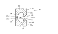
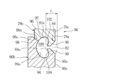
- Each shell 78, 80 forms a V-shaped groove portion 82 by abutting the respective open end portions 78a, 80a with each other.
- a bead-shaped weld 84 that is continuous around the entire circumference of the groove 82 is formed by one mag welding (CO2 gas arc welding) and joined. That is, the shells 78 and 80 are joined by one butt weld joint 86 formed by one welding operation.
- the opening end portions 78a and 80a are recessed inwardly at the root edge portions 88 and 90 forming the groove portions 82 and the side portions 78b and 80b of the shells 78 and 80, respectively.
- the concave portions 92 and 94 and seal portions 96 and 98 that are in contact with each other are formed successively in order from the outer peripheral surfaces 78c and 80c of the side portions 78b and 80b of the shells 78 and 80, respectively.
- Each root edge part 88,90, each recessed part 92,94, and each seal part 96,98 form the space 100 in which the inner end part 84a of the welding part 84 was located.
- the inner end portion 84 a is mainly composed of a molten metal obtained by melting the base material that is the shells 78 and 80 of the welded portion 84, and the molten metal reaches the seal portions 96 and 98 due to the presence of the space 100.
- the throat thickness L of the welded portion 84 for satisfying the pressure resistance performance as the sealed container 2 is secured, and after welding, the space 100 has the root edge portions 88 and 90, the concave portions 92 and 94, and the seals. Sealed by the portions 96 and 98 and the welded portion 84.
- the seal portions 96 and 98 are in contact with each other at inclined surfaces 96a and 98a inclined with respect to the abutting direction of the open end portions 78a and 80a.
- the inclined surfaces 96a and 98a are in contact with each other at a position above the groove portion 82 in a state where the space 100 is formed, and on the bottom shell 80 side, the inclined surface 98a is formed so that the seal portion 98 is convex. ing.
- the reason that the contact at each of the inclined surfaces 96a and 98a is possible is that the side portion 80b of the bottom shell 80 is slightly thicker than the side portion 78b of the top shell 78.
- the root portions 102 and 104 which are the boundaries between the concave portions 92 and 94 and the welded portion 84 are formed so that the wall surfaces 92a and 94a of the concave portions 92 and 94 and the inner end portion 84a of the welded portion 84 form an acute angle.
- the space 100 is formed in a substantially heart shape in sectional view.
- the two shells 78 and 80 are formed by one welding operation by welding the entire circumference of the groove portion 82 to form the weld portion 84. Since the sealed container 2 can be configured by joining with the butt weld joint 86, the assembly of the sealed container 2 can be performed in one man-hour, and the manufacturing cost of the sealed container 2 and thus the compressor 1 can be reduced. it can.
- the stress concentration at the joint between the welded portion 84 and the wall surface 92a is relaxed by forming the space 100, the occurrence of cracks is suppressed, and further, spatter and sparks scattered during welding are sealed.
- Welding is performed by ensuring the throat thickness L of the welded portion 84 while preventing the welded portion 2 from penetrating into the container 2 and preventing the welded portion 2 from penetrating the side portions 78b and 80b to reach the sealed container 2. Since the strength can be increased, the reliability of the compressor 1 can be improved.
- the seal portions 96, 98 are brought into contact with each other at the inclined surfaces 96a, 98a, so that the butt direction between the shells 78, 80 and the radial direction of the shells 78, 80 that are perpendicular to each other are assembled in both directions. Errors are acceptable. Therefore, the shells 78 and 80 can be easily positioned and assembled without strictly managing the dimensional accuracy of the shells 78 and 80.
- the root portions 102 and 104 are formed so that the wall surfaces 92a and 94a of the concave portions 92 and 94 and the inner end portion 84a of the weld portion 84 form an acute angle, whereby the concave portions 92 and 94 of the welded portions 84 and 94 are formed.
- the wall surfaces 92a, 94a and the welded portion 84 are smoothly continuous at a gentle angle, stress concentration and thus cracks caused by the stress hardly occur at the boundary between the welded portion 84 and the base metal that is each of the shells 78, 80.
- the welding strength of the portion 84 can be further increased.
- the space 100 has a substantially heart shape in cross section, so that the wall surfaces 92a, 94a of the respective recessed portions 92, 94 after welding and the welded portion 84 are smoothly continuous at a gentle angle, while the inner end portion of the welded portion 84 is formed. Since 84a and each seal part 96,98 can be separated as much as possible, the welding strength of the welding part 84 is improved, preventing the spatter
- the present invention is not limited to the above-described embodiments, and various modifications can be made.
- the seal portions 96 and 98 are brought into contact with each other at the inclined surfaces 96a and 98a.
- the contact with the inclined surfaces 96a and 98a is possible because the side portion 80b of the bottom shell 80 to be forged is slightly thicker than the side portion 78b of the top shell 78 to be press-formed. is there.
- each shell 78,80 can be shape
- the end surfaces of the seal portions 96 and 98 that are perpendicular to the abutting direction of the open end portions 78a and 80a. 96a1 and 98a1 may be formed, and these may be in contact with each other.
- the respective opening end portions 78a, Side surfaces 96a2 and 98a2 parallel to the butting direction of 80a may be formed, and these may be brought into contact with each other.
- the end surfaces 96a1 and 98a1 or the side surfaces 96a2 and 98a2 are formed, they are scattered during welding. It is possible to prevent spatter and sparks from entering the sealed container 2.
- each seal portion has a stepped shape, and a plurality of different surfaces, specifically, slopes 96a and 98a. Further, the side surfaces 96a2 and 98a2 may be in contact with each other. In this case, since stepwise sealing is possible, it is further ensured that spatter and sparks during welding enter the sealed container. This is preferable because it can be prevented.
- the space 100 has a heart shape. It is only necessary to form the space 100, which reduces stress concentration on at least the welded portion 84, suppresses the generation of cracks, and spatter and sparks scattered during welding enter the sealed container 2. Moreover, it can prevent that the welding part 84 penetrates the side parts 78b and 80b and it reaches the inside of the airtight container 2 can be prevented.
- the electric motor 4 is arranged on the upper part of the sealed container 2 and the compression mechanism 6 is arranged on the lower part of the sealed container 2, but the electric motor 4 is arranged on the lower part of the sealed container 2 and compressed.
- the mechanism 6 may be disposed on the top of the hermetic container 2.
- the top shell 78 covers the compression mechanism 6 side
- the bottom shell 80 covers the electric motor 4 side.
- the working fluid of the compressor 1 of the present embodiment is a carbon dioxide refrigerant, it is not limited to this.
- the working fluid is carbon dioxide refrigerant
- the pressure of the working fluid discharged from the compression mechanism 6 becomes high to the supercritical state, and the pressure acting in the sealed container 2 may be high.
- thickening of the sealed container 2 is unavoidable, and high weld strength is also required for the welded portion 84 between the shells 78 and 80.
- the above configuration is preferable because the welding strength of the welded portion 84 can be increased, and the reliability of the compressor 1 can be improved.
- the present Example demonstrates the positive displacement compressor 1, this invention is applicable to general sealed fluid machines, such as a scroll compressor and an expander, and these fluid machines are used as a vending machine. Needless to say, it can be used as a component device of a refrigeration cycle incorporated in the apparatus.
Landscapes
- Engineering & Computer Science (AREA)
- Mechanical Engineering (AREA)
- Physics & Mathematics (AREA)
- Plasma & Fusion (AREA)
- General Engineering & Computer Science (AREA)
- Compressor (AREA)
- Butt Welding And Welding Of Specific Article (AREA)
- Applications Or Details Of Rotary Compressors (AREA)
- Details Of Reciprocating Pumps (AREA)
Abstract
Description
特許文献1に記載の密閉容器は、筒状のセンターシェルと、センターシェルの両開口端部にそれぞれ溶接されるカップ状のトップシェル、ボトムシェルとの3部材から構成され、各シェル同士は溶接部の溶融金属に溶接進行方向の作用力を与えながら溶接して接合される。
そこで、密閉容器をトップシェル、ボトムシェルの2部材のみから構成すれば、溶接箇所が少なくなり、密閉容器の組立工数も減らせ、密閉容器の製造コストを低減することができると考えられる。
ある。
また、各シール部は、各開口端部の突き合わせ方向に対して傾斜した斜面で互いに当接される(請求項3)。
更に、各シール部は、複数の異なる面で互いに当接される(請求項4)。
更にまた、空間は断面視略ハート形をなす(請求項6)。
また、密閉容器内には、被駆動ユニットに吸入され、被駆動ユニットから吐出される作動流体の圧力が作用し、作動流体は二酸化炭素冷媒である(請求項7)。
また、空間を形成することにより、溶接部への応力集中が緩和されるため、亀裂の発生が抑制され、更に、溶接時に飛散するスパッタや火花が密閉容器内に侵入することを防止し、また、溶接部が密閉容器内にまで至ることを防止しながら、溶接部ののど厚を確保して溶接強度を高めることができるため、流体機械の信頼性を向上することができる。
請求項4記載の発明によれば、溶接時のスパッタや火花は各シェルの径方向中心に向けて飛散しがちであるが、各シール部を複数の異なる面で互いに当接させることにより、段階的なシールが可能となるため、溶接時のスパッタや火花が密閉容器内に侵入することを更に確実に防止することができる。
請求項6記載の発明によれば、空間は断面視略ハート形をなすことにより、溶接後の各凹部の壁面と溶接部とが緩い角度で滑らかに連続しつつ、溶接部の内端部と各シール部とを極力離間させることができるため、溶接時のスパッタや火花が密閉容器内に侵入することを効果的に防止しつつ、溶接部の溶接強度を高めることができる。
圧縮機1は、密閉型の往復動圧縮機であり、詳しくはレシプロ圧縮機やピストン圧縮機と称される容積式圧縮機に分類され、例えば自動販売機に組み込まれた図示しない冷凍サイクルの構成機器として使用される。
冷凍サイクルは、圧縮機1の作動流体としての冷媒が循環する経路を備え、冷媒には例えば非可燃性の自然冷媒である二酸化炭素冷媒が用いられる。
電動モータ4は、給電により磁界を発生するステータ8と、ステータ8で発生した磁界により回転するロータ10とから構成され、ロータ10はステータ8の内側の同軸上に配置され、後述するクランクシャフト14の主軸部24に焼き嵌め固定されている。ステータ8には密閉容器2に固定された電装部12、及び図示しないリード線を介して圧縮機1外から給電される。
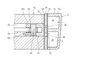
図2に示されるように、シリンダブロック16には、シリンダボア26が一体に形成され、シリンダボア26の開口を閉じるように、シリンダブロック16側から順にシリンダガスケット28、後述する吸入バルブ50、バルブプレート30、ヘッドガスケット32、シリンダヘッド34がボルトによって押圧固定されている。
詳しくは、電動モータ4及び圧縮機構6はフレーム36の下部の台座部38にて支持され、フレーム36は台座部38にて密閉容器2に固定されている。一方、フレーム36の上部の円筒部40においては、その内周面40aに主軸部24の軸受42が配置され、円筒部40の上端面40bにはロータ10のスラスト荷重を受けるスラストレース(ベアリング)またはスラストワッシャなどの軸受44が配置されている。
シリンダヘッド34は冷媒の吸入室54、吐出室56を備え、ピストン18の圧縮行程において吐出バルブ52が開くことにより、吐出室56は吐出孔48を介してシリンダボア26と連通する。一方、ピストン18の吸入行程において吸入バルブ50が開くことにより、吸入室54は吸入孔46を介してシリンダボア26と連通する。
密閉容器2内には冷媒の主として吐出圧力が作用し、密閉容器2の内底部2aには、軸受42,44といった、電動モータ4及び圧縮機構6の各摺動部を潤滑する潤滑油が少量貯留される。
圧縮機1では、ステータ8に給電することによって主軸部24に固定されたロータ10が回転され、ひいてはクランクシャフト14が回転され、コネクティングロッド20を介しピストン18がシリンダボア26内で往復運動する。そして、このピストン18の往復運動により、冷凍サイクルからシリンダボア26へ冷媒が吸入され、この冷媒はシリンダボア26で圧縮され、更に冷凍サイクルへ吐出される。
シリンダボア26内の圧力が冷媒の吸入圧力以下になると、シリンダボア26内の圧力と吸入室54内の圧力との差に応じて吸入バルブ50が開く。そして、冷凍サイクルの冷媒は、吸入パイプ58を経て吸入室54に導かれ、吸入孔46を経てシリンダボア26内に吸入される。
一方、ボトムシェル80は、S20C、S25Cなどの軟質鋼を鍛造成型にて8.5mm程度の厚さに極力薄く形成され、トップシェル78と同様に高圧冷媒に対する耐圧強度が確保されている。
各ルートエッジ部88,90、各凹部92,94、及び各シール部96,98は、溶接部84の内端部84aが位置づけられた空間100を形成している。
各斜面96a,98aは、空間100が形成された状態において開先部82よりも上側の位置で当接され、ボトムシェル80側においては、斜面98aはシール部98が凸となるように形成されている。このような各斜面96a,98aでの当接が可能なのは、トップシェル78の側部78bよりもボトムシェル80の側部80bのほうが厚みが若干大きいことによるものである。
上述した第1実施例の圧縮機1は、開先部82に全周溶接をして溶接部84を形成することにより、2つのシェル78,80を1回の溶接作業で形成された1箇所の突き合わせ溶接継ぎ手86で接合して密閉容器2を構成することができるため、密閉容器2の組立を1工数で行うことができ、密閉容器2、ひいては圧縮機1の製造コストを低減することができる。
また、各凹部92,94の壁面92a,94aと溶接部84の内端部84aとが鋭角をなすようにしてルート部102,104が形成されることにより、溶接後の各凹部92,94の壁面92a,94aと溶接部84とが緩い角度で滑らかに連続するため、溶接部84と各シェル78,80である母材との境目に、応力集中ひいてはそれに起因する亀裂が生じ難くなり、溶接部84の溶接強度を更に高めることができる。
具体的には、上記実施例では、各シール部96,98は斜面96a,98aで互いに当接される。このような斜面96a,98aでの当接が可能なのは、プレス成型されるトップシェル78の側部78bよりも、鍛造成型されるボトムシェル80の側部80bのほうが厚みが若干大きいことによるものである。
2 密閉容器
4 電動モータ(駆動ユニット)
6 圧縮機構(被駆動ユニット)
78 トップシェル(第1シェル)
78a 開口端部
80 ボトムシェル(第2シェル)
80a 開口端部
82 開先部
84 溶接部
84a 内端部
88 ルートエッジ部
90 ルートエッジ部
92 凹部
92a 壁面
94 凹部
94a 壁面
96 シール部
96a 斜面
96a1 端面
96a2 側面
98 シール部
98a 斜面
98a1 端面
98a2 側面
100 空間
102 ルート部
104 ルート部
Claims (7)
- 密閉容器内に、駆動ユニットと、前記駆動ユニットの駆動力が伝達される被駆動ユニットとが収容される流体機械であって、
前記密閉容器は、前記駆動ユニット側を覆う第1シェルと、前記第1シェルに接合され、前記被駆動ユニット側を覆う第2シェルとからなり、
前記第1及び前記第2シェルは、これらの各開口端部を突き合わせて形成される開先部に全周溶接をして溶接部を形成し、前記溶接部は、前記各開口端部にて互いに当接されるシール部と所定の空間を存して離間することを特徴とする流体機械。 - 前記空間は、前記開先部を形成するルートエッジ部と、前記各開口端部の内方に凹まされた凹部と、前記シール部とから形成されることを特徴とする請求項1に記載の流体機械。
- 前記各シール部は、前記各開口端部の突き合わせ方向に対して傾斜した斜面で互いに当接されることを特徴とする請求項1または2に記載の流体機械。
- 前記各シール部は、複数の異なる面で互いに当接されることを特徴とする請求項1乃至3の何れかに記載の流体機械。
- 前記各凹部と前記溶接部との境目であるルート部は、前記各凹部の壁面と前記溶接部の内端部とが鋭角をなすようにして形成されることを特徴とする請求項2乃至4の何れかに記載の流体機械。
- 前記空間は断面視略ハート形をなすことを特徴とする請求項5に記載の流体機械。
- 前記密閉容器内には、前記被駆動ユニットに吸入され、前記被駆動ユニットから吐出される作動流体の圧力が作用し、前記作動流体は二酸化炭素冷媒であることを特徴とする請求項1乃至6の何れかに記載の流体機械。
Priority Applications (6)
| Application Number | Priority Date | Filing Date | Title |
|---|---|---|---|
| CA2787312A CA2787312C (en) | 2010-01-27 | 2011-01-24 | Fluid machine |
| KR1020127020416A KR101358931B1 (ko) | 2010-01-27 | 2011-01-24 | 유체 기계 |
| MX2012008749A MX2012008749A (es) | 2010-01-27 | 2011-01-24 | Maquina de fluido. |
| US13/575,883 US8961161B2 (en) | 2010-01-27 | 2011-01-24 | Fluid machine provided with hermetic container that is subjected to pressure of working fluid |
| EP11736770.6A EP2518318B1 (en) | 2010-01-27 | 2011-01-24 | Fluid machine |
| CN201180007190.4A CN102844567B (zh) | 2010-01-27 | 2011-01-24 | 流体机械 |
Applications Claiming Priority (2)
| Application Number | Priority Date | Filing Date | Title |
|---|---|---|---|
| JP2010015414A JP5520063B2 (ja) | 2010-01-27 | 2010-01-27 | 流体機械 |
| JP2010-015414 | 2010-06-23 |
Publications (1)
| Publication Number | Publication Date |
|---|---|
| WO2011093053A1 true WO2011093053A1 (ja) | 2011-08-04 |
Family
ID=44319052
Family Applications (1)
| Application Number | Title | Priority Date | Filing Date |
|---|---|---|---|
| PCT/JP2011/000368 Ceased WO2011093053A1 (ja) | 2010-01-27 | 2011-01-24 | 流体機械 |
Country Status (8)
| Country | Link |
|---|---|
| US (1) | US8961161B2 (ja) |
| EP (1) | EP2518318B1 (ja) |
| JP (1) | JP5520063B2 (ja) |
| KR (1) | KR101358931B1 (ja) |
| CN (1) | CN102844567B (ja) |
| CA (1) | CA2787312C (ja) |
| MX (1) | MX2012008749A (ja) |
| WO (1) | WO2011093053A1 (ja) |
Families Citing this family (8)
| Publication number | Priority date | Publication date | Assignee | Title |
|---|---|---|---|---|
| US9873557B2 (en) * | 2013-08-12 | 2018-01-23 | Tek Global S.R.L. | Disposable canister for sealant for inflatable article repair and inflation kit, and production thereof |
| JP2015088643A (ja) | 2013-10-31 | 2015-05-07 | セイコーエプソン株式会社 | 電子デバイスの製造方法、電子デバイス、電子機器、移動体、および蓋体 |
| JP2015088644A (ja) * | 2013-10-31 | 2015-05-07 | セイコーエプソン株式会社 | 電子デバイスの製造方法、電子デバイス、電子機器、移動体、および蓋体 |
| US10626870B2 (en) * | 2015-06-11 | 2020-04-21 | Bitzer Kuehlmaschinenbau Gmbh | Ring weld blocker in discharge check valve |
| JP6355601B2 (ja) * | 2015-08-21 | 2018-07-11 | 株式会社アドヴィックス | アキュムレータ |
| CN106938368B (zh) * | 2017-05-03 | 2023-09-19 | 桂林实创真空数控设备有限公司 | 一种带x射线防护的直线局部动密封运动机构 |
| CN112696396B (zh) * | 2019-10-23 | 2025-07-22 | 赛力达液压机械(昆山)有限公司 | 一种缸筒的焊接结构 |
| AT17173U8 (de) * | 2019-12-19 | 2021-09-15 | Anhui meizhi compressor co ltd | Hermetisch gekapselter Kältemittelverdichter |
Citations (6)
| Publication number | Priority date | Publication date | Assignee | Title |
|---|---|---|---|---|
| JPS5165048A (ja) * | 1974-10-28 | 1976-06-05 | Bbc Brown Boveri & Cie | |
| JPS5517712A (en) * | 1978-07-21 | 1980-02-07 | Hitachi Ltd | Sealing mechanism for flange portion of pressure vessel |
| JPH07119637A (ja) * | 1993-10-28 | 1995-05-09 | Hitachi Ltd | 密閉形圧縮機容器の溶接方法 |
| JP2004293463A (ja) * | 2003-03-27 | 2004-10-21 | Matsushita Electric Ind Co Ltd | 密閉型圧縮機 |
| JP2005226610A (ja) * | 2004-02-16 | 2005-08-25 | Sanyo Electric Co Ltd | コンプレッサ用密閉容器及びコンプレッサ |
| JP2005349404A (ja) | 2004-06-08 | 2005-12-22 | Matsushita Electric Ind Co Ltd | 流体機械の製造方法及び流体機械 |
Family Cites Families (8)
| Publication number | Priority date | Publication date | Assignee | Title |
|---|---|---|---|---|
| GB1174459A (en) * | 1966-11-10 | 1969-12-17 | Danfoss As | Housing for a Refrigerator Compressor Unit. |
| KR0153343B1 (ko) * | 1995-10-13 | 1999-03-20 | 김광호 | 왕복동형 압축기 |
| JPH10318140A (ja) * | 1997-05-21 | 1998-12-02 | Matsushita Refrig Co Ltd | 密閉型電動圧縮機 |
| JPH11257229A (ja) | 1998-03-05 | 1999-09-21 | Matsushita Refrig Co Ltd | 密閉型コンプレッサとその製造方法 |
| KR100483556B1 (ko) * | 2002-09-17 | 2005-04-15 | 삼성광주전자 주식회사 | 밀폐형 압축기의 케이스 |
| KR100517459B1 (ko) * | 2003-04-28 | 2005-09-29 | 삼성광주전자 주식회사 | 밀폐형 압축기 |
| US7179061B2 (en) | 2003-06-09 | 2007-02-20 | Tecumseh Products Company | Multi-layer compressor housing and method of manufacture |
| DE102004062305A1 (de) * | 2004-12-23 | 2006-07-13 | BSH Bosch und Siemens Hausgeräte GmbH | Verdichtergehäuse |
-
2010
- 2010-01-27 JP JP2010015414A patent/JP5520063B2/ja not_active Expired - Fee Related
-
2011
- 2011-01-24 EP EP11736770.6A patent/EP2518318B1/en not_active Not-in-force
- 2011-01-24 KR KR1020127020416A patent/KR101358931B1/ko not_active Expired - Fee Related
- 2011-01-24 CN CN201180007190.4A patent/CN102844567B/zh not_active Expired - Fee Related
- 2011-01-24 WO PCT/JP2011/000368 patent/WO2011093053A1/ja not_active Ceased
- 2011-01-24 CA CA2787312A patent/CA2787312C/en not_active Expired - Fee Related
- 2011-01-24 US US13/575,883 patent/US8961161B2/en not_active Expired - Fee Related
- 2011-01-24 MX MX2012008749A patent/MX2012008749A/es active IP Right Grant
Patent Citations (6)
| Publication number | Priority date | Publication date | Assignee | Title |
|---|---|---|---|---|
| JPS5165048A (ja) * | 1974-10-28 | 1976-06-05 | Bbc Brown Boveri & Cie | |
| JPS5517712A (en) * | 1978-07-21 | 1980-02-07 | Hitachi Ltd | Sealing mechanism for flange portion of pressure vessel |
| JPH07119637A (ja) * | 1993-10-28 | 1995-05-09 | Hitachi Ltd | 密閉形圧縮機容器の溶接方法 |
| JP2004293463A (ja) * | 2003-03-27 | 2004-10-21 | Matsushita Electric Ind Co Ltd | 密閉型圧縮機 |
| JP2005226610A (ja) * | 2004-02-16 | 2005-08-25 | Sanyo Electric Co Ltd | コンプレッサ用密閉容器及びコンプレッサ |
| JP2005349404A (ja) | 2004-06-08 | 2005-12-22 | Matsushita Electric Ind Co Ltd | 流体機械の製造方法及び流体機械 |
Non-Patent Citations (1)
| Title |
|---|
| See also references of EP2518318A4 * |
Also Published As
| Publication number | Publication date |
|---|---|
| CN102844567A (zh) | 2012-12-26 |
| CA2787312C (en) | 2014-10-21 |
| CN102844567B (zh) | 2015-05-06 |
| US8961161B2 (en) | 2015-02-24 |
| KR20120112719A (ko) | 2012-10-11 |
| EP2518318B1 (en) | 2014-12-03 |
| EP2518318A4 (en) | 2013-08-28 |
| EP2518318A1 (en) | 2012-10-31 |
| US20120308378A1 (en) | 2012-12-06 |
| CA2787312A1 (en) | 2011-08-04 |
| KR101358931B1 (ko) | 2014-02-05 |
| JP2011153565A (ja) | 2011-08-11 |
| JP5520063B2 (ja) | 2014-06-11 |
| MX2012008749A (es) | 2012-11-23 |
Similar Documents
| Publication | Publication Date | Title |
|---|---|---|
| JP5520063B2 (ja) | 流体機械 | |
| WO2011089924A1 (ja) | 流体機械 | |
| JP5935579B2 (ja) | 容積形圧縮機 | |
| JP2011153526A (ja) | 密閉型ロータリ圧縮機 | |
| JP2010236449A (ja) | 回転式流体機械、回転式流体機械の固定部材、及び回転式流体機械の固定部材の加工方法 | |
| US20120308410A1 (en) | Fluid Machine | |
| JP6036797B2 (ja) | スクロール圧縮機 | |
| US20100034679A1 (en) | Refrigerant compressor, piston of a refrigerant compressor and piston arrangement | |
| JP6945128B2 (ja) | 圧縮機 | |
| US12631169B2 (en) | Reciprocating compressor | |
| JP2013096349A (ja) | 密閉形圧縮機 | |
| JP2011163177A (ja) | 往復動型圧縮機 | |
| US20240418158A1 (en) | Reciprocating compressor | |
| WO2011093085A1 (ja) | 流体機械 | |
| KR102351707B1 (ko) | 왕복동식 압축기의 피스톤 및 그 제조방법 | |
| KR20260004832A (ko) | 왕복동식 압축기 | |
| JP2002070744A (ja) | 冷媒圧縮機 | |
| JP2013100797A (ja) | 密閉型圧縮機 | |
| JP2019178652A (ja) | 圧縮機 | |
| JP2011058395A (ja) | 密閉型圧縮機 | |
| JP2012057594A (ja) | 密閉型圧縮機 | |
| JP2006104958A (ja) | スクロール圧縮機 | |
| JP2009097482A (ja) | 流体機械 | |
| JP2007154744A (ja) | スクロール膨張機 |
Legal Events
| Date | Code | Title | Description |
|---|---|---|---|
| WWE | Wipo information: entry into national phase |
Ref document number: 201180007190.4 Country of ref document: CN |
|
| 121 | Ep: the epo has been informed by wipo that ep was designated in this application |
Ref document number: 11736770 Country of ref document: EP Kind code of ref document: A1 |
|
| ENP | Entry into the national phase |
Ref document number: 2787312 Country of ref document: CA |
|
| WWE | Wipo information: entry into national phase |
Ref document number: 6471/DELNP/2012 Country of ref document: IN |
|
| WWE | Wipo information: entry into national phase |
Ref document number: 2011736770 Country of ref document: EP |
|
| NENP | Non-entry into the national phase |
Ref country code: DE |
|
| WWE | Wipo information: entry into national phase |
Ref document number: 1201003826 Country of ref document: TH Ref document number: 13575883 Country of ref document: US Ref document number: MX/A/2012/008749 Country of ref document: MX |
|
| ENP | Entry into the national phase |
Ref document number: 20127020416 Country of ref document: KR Kind code of ref document: A |
|
| REG | Reference to national code |
Ref country code: BR Ref legal event code: B01A Ref document number: 112012018672 Country of ref document: BR |
|
| REG | Reference to national code |
Ref country code: BR Ref legal event code: B01E Ref document number: 112012018672 Country of ref document: BR |
|
| ENPW | Started to enter national phase and was withdrawn or failed for other reasons |
Ref document number: 112012018672 Country of ref document: BR Free format text: PEDIDO RETIRADO POR NAO CUMPRIMENTO DA EXIGENCIA PUBLICADA NA RPI 2482 DE 31/07/2018 |