WO2011096120A1 - 熱交換器 - Google Patents
熱交換器 Download PDFInfo
- Publication number
- WO2011096120A1 WO2011096120A1 PCT/JP2010/069768 JP2010069768W WO2011096120A1 WO 2011096120 A1 WO2011096120 A1 WO 2011096120A1 JP 2010069768 W JP2010069768 W JP 2010069768W WO 2011096120 A1 WO2011096120 A1 WO 2011096120A1
- Authority
- WO
- WIPO (PCT)
- Prior art keywords
- fin
- heat exchanger
- fin member
- curved
- pipe
- Prior art date
- Legal status (The legal status is an assumption and is not a legal conclusion. Google has not performed a legal analysis and makes no representation as to the accuracy of the status listed.)
- Ceased
Links
Images






Classifications
-
- F—MECHANICAL ENGINEERING; LIGHTING; HEATING; WEAPONS; BLASTING
- F28—HEAT EXCHANGE IN GENERAL
- F28F—DETAILS OF HEAT-EXCHANGE AND HEAT-TRANSFER APPARATUS, OF GENERAL APPLICATION
- F28F1/00—Tubular elements; Assemblies of tubular elements
- F28F1/10—Tubular elements and assemblies thereof with means for increasing heat-transfer area, e.g. with fins, with projections, with recesses
-
- F—MECHANICAL ENGINEERING; LIGHTING; HEATING; WEAPONS; BLASTING
- F28—HEAT EXCHANGE IN GENERAL
- F28D—HEAT-EXCHANGE APPARATUS, NOT PROVIDED FOR IN ANOTHER SUBCLASS, IN WHICH THE HEAT-EXCHANGE MEDIA DO NOT COME INTO DIRECT CONTACT
- F28D1/00—Heat-exchange apparatus having stationary conduit assemblies for one heat-exchange medium only, the media being in contact with different sides of the conduit wall, in which the other heat-exchange medium is a large body of fluid, e.g. domestic or motor car radiators
- F28D1/02—Heat-exchange apparatus having stationary conduit assemblies for one heat-exchange medium only, the media being in contact with different sides of the conduit wall, in which the other heat-exchange medium is a large body of fluid, e.g. domestic or motor car radiators with heat-exchange conduits immersed in the body of fluid
- F28D1/04—Heat-exchange apparatus having stationary conduit assemblies for one heat-exchange medium only, the media being in contact with different sides of the conduit wall, in which the other heat-exchange medium is a large body of fluid, e.g. domestic or motor car radiators with heat-exchange conduits immersed in the body of fluid with tubular conduits
- F28D1/047—Heat-exchange apparatus having stationary conduit assemblies for one heat-exchange medium only, the media being in contact with different sides of the conduit wall, in which the other heat-exchange medium is a large body of fluid, e.g. domestic or motor car radiators with heat-exchange conduits immersed in the body of fluid with tubular conduits the conduits being bent, e.g. in a serpentine or zig-zag
- F28D1/0477—Heat-exchange apparatus having stationary conduit assemblies for one heat-exchange medium only, the media being in contact with different sides of the conduit wall, in which the other heat-exchange medium is a large body of fluid, e.g. domestic or motor car radiators with heat-exchange conduits immersed in the body of fluid with tubular conduits the conduits being bent, e.g. in a serpentine or zig-zag the conduits being bent in a serpentine or zig-zag
-
- F—MECHANICAL ENGINEERING; LIGHTING; HEATING; WEAPONS; BLASTING
- F28—HEAT EXCHANGE IN GENERAL
- F28F—DETAILS OF HEAT-EXCHANGE AND HEAT-TRANSFER APPARATUS, OF GENERAL APPLICATION
- F28F1/00—Tubular elements; Assemblies of tubular elements
- F28F1/10—Tubular elements and assemblies thereof with means for increasing heat-transfer area, e.g. with fins, with projections, with recesses
- F28F1/12—Tubular elements and assemblies thereof with means for increasing heat-transfer area, e.g. with fins, with projections, with recesses the means being only outside the tubular element
- F28F1/126—Tubular elements and assemblies thereof with means for increasing heat-transfer area, e.g. with fins, with projections, with recesses the means being only outside the tubular element consisting of zig-zag shaped fins
-
- F—MECHANICAL ENGINEERING; LIGHTING; HEATING; WEAPONS; BLASTING
- F28—HEAT EXCHANGE IN GENERAL
- F28F—DETAILS OF HEAT-EXCHANGE AND HEAT-TRANSFER APPARATUS, OF GENERAL APPLICATION
- F28F1/00—Tubular elements; Assemblies of tubular elements
- F28F1/10—Tubular elements and assemblies thereof with means for increasing heat-transfer area, e.g. with fins, with projections, with recesses
- F28F1/12—Tubular elements and assemblies thereof with means for increasing heat-transfer area, e.g. with fins, with projections, with recesses the means being only outside the tubular element
- F28F1/24—Tubular elements and assemblies thereof with means for increasing heat-transfer area, e.g. with fins, with projections, with recesses the means being only outside the tubular element and extending transversely
- F28F1/32—Tubular elements and assemblies thereof with means for increasing heat-transfer area, e.g. with fins, with projections, with recesses the means being only outside the tubular element and extending transversely the means having portions engaging further tubular elements
-
- F—MECHANICAL ENGINEERING; LIGHTING; HEATING; WEAPONS; BLASTING
- F28—HEAT EXCHANGE IN GENERAL
- F28F—DETAILS OF HEAT-EXCHANGE AND HEAT-TRANSFER APPARATUS, OF GENERAL APPLICATION
- F28F9/00—Casings; Header boxes; Auxiliary supports for elements; Auxiliary members within casings
- F28F9/001—Casings in the form of plate-like arrangements; Frames enclosing a heat exchange core
- F28F9/002—Casings in the form of plate-like arrangements; Frames enclosing a heat exchange core with fastening means for other structures
-
- F—MECHANICAL ENGINEERING; LIGHTING; HEATING; WEAPONS; BLASTING
- F28—HEAT EXCHANGE IN GENERAL
- F28F—DETAILS OF HEAT-EXCHANGE AND HEAT-TRANSFER APPARATUS, OF GENERAL APPLICATION
- F28F2215/00—Fins
- F28F2215/12—Fins with U-shaped slots for laterally inserting conduits
Definitions
- the present invention relates to an air-cooled heat exchanger that is mainly mounted under the floor of an automobile or at the lower part of an engine room, particularly under an engine front.
- Patent Document 1 a heat exchanger in which corrugated fin members are arranged on a meander-formed tube member has been known.
- This heat exchanger can be made compact by forming the pipe member in a meandering manner, making it possible to lengthen the flow path of the fluid flowing through the inside of the pipe member, and by using corrugated fin members, a large number of pipe members can be used. It is possible to arrange the fins, and the heat exchange performance can be improved.
- the pipe member is formed in a meandering manner to reduce the bulk of the heat exchanger in the thickness direction, so that the floor of an automobile or the lower part of an engine room is formed.
- the stepping stones from the road surface are in direct contact with the pipe member and damaged during traveling, and stress concentration occurs in the recess formed by this damage due to external force due to vibration, etc.
- An object of the present invention is to obtain a heat exchanger capable of preventing a situation where a pipe member is damaged.
- the present invention repeatedly folds and stacks plate materials into a corrugated shape to form corrugated fins, and press-deforms the curved portion formed by the bending processing into a concave shape.
- a plurality of fin members formed with engaging recesses, and a plurality of straight pipe portions arranged in parallel via the fin members and the straight pipe portions having meandering pipe members having U-shaped folded portions.
- the plurality of straight pipe portions of the pipe member are engaged with the engagement concave portions of the plurality of fin members.
- the present invention is such that a fin member formed of corrugated fins is assembled to a meandering tube member in which a plurality of straight pipe portions are integrally formed. It can arrange
- the fin member is formed of corrugated fins, the surface area of the fin member can be increased due to the presence of the curved portion formed between the fins of the corrugated fin. Therefore, it is possible to efficiently dissipate heat from the pipe member, and heat exchange performance can be improved.
- a one-stage heat exchanger different from the two-stage heat exchanger described in Patent Document 1 is formed. Can be easily mounted under the floor.
- the outer diameter of the pipe member is 8 mm to 12 mm.
- the outer diameter of the pipe member is less than 8 mm, especially when a liquid such as oil, gasoline, or light oil is used as the fluid in the pipe, it becomes difficult to ensure the required flow rate because the pressure loss of the fluid increases. The flow rate decreases and it becomes difficult to obtain a desired amount of exchange heat, or the pressure loss exceeds a threshold value and it becomes impossible to use.
- the diameter is larger than 12.0 mm, the outer diameter of the pipe member is increased. Therefore, although the required flow rate of the fluid is easily secured as the outer diameter increases, the entire product becomes bulky and the automobile As a result, the mountability in a narrow space such as under the floor of the vehicle or in the lower part of the engine room is reduced.
- the facing interval between the curved tops that protrude outwardly at the curved portions of the adjacent fin members is set to 0.5 to 5.0 mm.
- the curved top part in this invention means the top part most projected in the bending width direction of the fin member in the curved part of the fin member curvedly formed by the bending process of a board
- interval is larger than 5.0 mm, it becomes necessary to arrange
- the facing distance between the adjacent fin members becomes narrow, so that the stepping stones from the road surface are less likely to enter the facing distance, and the stepping stones are on the surface of the pipe member during traveling. Since the tube member surface is damaged by stepping stones and a recess is formed, and the recess is prevented from being damaged due to stress concentration due to external forces such as vibration. Is preferable. However, in order to make the facing interval less than 0.5 mm, the protruding portions of adjacent fin members must be arranged close to each other.
- the facing interval means a disposition interval between adjacent fin members facing each other through the tube member, and in particular, an engagement recess that does not involve the tube member between both fin members. It means an interval at the curved top protruding from the fin member in the width direction.
- the protruding height in the width direction of the fin member from the surface of the straight pipe portion of the pipe member is set to 11 mm or less.
- the reason for this is that if the protrusion height in the width direction of the fin member is larger than 11 mm, the entire product assembled with the fin member becomes bulky, and the mountability to an automobile or the like is reduced. From the calculation of the fin efficiency of the fin member shown, it became clear that a significant improvement in heat exchange performance cannot be expected.
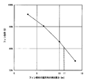
- the relationship between the protrusion height of a fin member and the fin efficiency regarding the heat exchange performance of a fin member is demonstrated below.
- the said fin efficiency means the heat dissipation efficiency of the fin member which changes with the shape of a fin member, the height of a fin member, and the plate
- the protrusion height in the width direction of the fin member exceeds 11 mm, the fin efficiency is lower than 80%, and the heat exchange efficiency is lowered, while the protrusion height of the fin member is 11 mm or less.
- the fin efficiency can be secured at 80% or more, and the heat exchange efficiency can be maintained well. Therefore, in order to maintain the heat exchange efficiency of the present invention satisfactorily, the protrusion height in the width direction of the fin member needs to be 11 mm or less.
- the protrusion height in the width direction of the fin member is limited to 11 mm or less, and in the present invention, the protrusion height of the fin member is set such that the facing interval between the curved top portions is 0.5 to 5.0 mm.
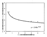
- the mathematical formula of y ⁇ 2.46x ⁇ 0.29 (y: protrusion height in the width direction of the fin member from the surface of the pipe member / opposite spacing of the curved tops, x: opposing spacing of the curved tops) The value is established. This formula is derived from the following experiment and simulation analysis.
- the facing interval t between the curved tops of the fin member is set to 2.0 mm
- the plate thickness of the fin member is set to 0.3 mm
- the fin member A stepping stone test was conducted when the protruding height L in the width direction was 3 mm and 4 mm.
- This stepping stone test is an automotive standard JASO M 104 “Brake tube test method” (category: first category, purpose of the test; test method and test for the purpose of deteriorating the outer surface of the brake tube, such as an organic coating.
- the test conditions and test equipment of the same standard are mainly as follows, according to the stepping stone test (test method item number 5.1)).
- 3 and 4 show the results of the stepping stone test using the above polishing stone.
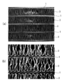
- 3A is an enlarged plan view of the heat exchanger before the stepping stone test when the protrusion height L in the width direction of the fin member is 4 mm
- FIG. 3B is the width direction of the fin member.
- It is an expansion plane photograph of the heat exchanger after a stepping stone test in case protrusion height L of 4 mm
- FIG. 4A is an enlarged plan view of the heat exchanger before the stepping stone test when the protrusion height L in the width direction of the fin member is 3 mm
- FIG. 4B is the width direction of the fin member.
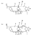
- FIGS. 5 and 6 are schematic cross-sectional views of the heat exchanger in a direction perpendicular to the tube axis direction of the straight tube portion of the tube member.
- FIG. 5A is a schematic diagram in the case where the protrusion height L in the width direction of the fin member is 3 mm
- FIG. 5B is a case in which the protrusion height L in the width direction of the fin member is 4 mm. It is a schematic diagram.
- the stepping stone (21) is shown in the schematic diagram shown in FIG. 5 when the protrusion height L in the width direction of the fin member (3) is 3 mm (FIG. 5A). Is in contact with the surface of the pipe member (1), and the projection height L in the width direction of the fin member (3) is 4 mm (FIG. 5B), the surface of the pipe member (1).
- the shape of the heat exchanger (20) is schematically shown so that the shortest distance P between the stepping stone and the stepping stone (21) is 1 mm.
- the shape of the stepping stone when contacting the surface of the pipe member was determined as an inverted triangle.
- the limit value of the shortest distance between the pipe member (1) and the stepping stone (21) when the stepping stone (21) does not directly hit the pipe member (1). If the distance between the tube member and the stepping stone is at least 1 mm or more in the schematic diagram, it is assumed that the stepping stone does not directly hit the tube member even during actual travel.
- each facing distance t and the protrusion in the width direction of the fin member when the facing distance t is 0.5 mm, 1 mm, 4 mm, and 5 mm.
- FIGS. 6A to 6D regarding the relationship with the height L, a schematic diagram was created for each facing interval, and a simulation analysis was performed.
- the facing interval t is 0.5 mm in (a)
- the facing interval t is 1 mm in (b)
- the facing interval t is 4 mm in (c)
- the facing interval t is 5 mm in (d).
- a schematic diagram is shown respectively.
- the shortest distance P of a stepping stone (21) and the surface of a pipe member (1) will be 1 mm, ie, the protrusion height L of the fin member that a stepping stone does not hit a pipe member directly.
- the lower limit value was determined from the schematic diagram shown in FIG.
- the protrusion height in the width direction of the fin member (3) when the distance P between the surface of the pipe member (1) and the stepping stone (21) is 1 mm.
- L is 1.7 mm when the facing distance t is 0.5 mm, 2.5 mm when the facing distance t is 1 mm, 7.0 mm when the facing distance t is 4 mm, and 8 when the facing distance t is 5 mm. 0.5 mm.
- interval t was made into the minimum value of the protrusion height of the fin member in which a stepping stone does not directly hit the surface of a pipe member in each opposing space
- the protrusion height in the width direction of the fin member is y ⁇ 2.46x ⁇ .
- the fin member may have a plate thickness of 0.2 mm to 0.5 mm. If the plate thickness is less than 0.2 mm, the fin member becomes thin, so the heat capacity of the fin becomes poor, the temperature of the fin decreases rapidly, the heat exchange efficiency decreases, and the strength of the fin decreases. This makes it easier for the stepping stones to come into contact with the surface of the pipe member. If the thickness is greater than 0.5 mm, the strength is improved, but the heat exchange efficiency is somewhat improved, but a significant improvement cannot be expected, so the material is wasted.
- the fin member may have a fin arrangement interval of 1.6 mm to 2.2 mm formed by bending.
- interval of the said fin means the separation distance of the pipe axis direction of the straight pipe part of the tube member between adjacent fins in the several fin part formed in the fin member by the bending process. is there.
- the numerical range of the fin arrangement interval of 1.6 mm to 2.2 mm is based on the following cooling performance test results. The cooling performance test will be described.
- the plate thickness of the aluminum alloy fin member is 0.3 mm
- the tensile strength of the mechanical properties is 200 MPa
- the fin arrangement interval is 1.6 mm, 2.0 mm
- the heat exchanger was created for every arrangement
- the relationship between the drop temperature of the fluid in the pipe of each heat exchanger obtained in this way and the arrangement interval of the fins of each heat exchanger was plotted and represented by a graph as shown in FIG. From FIG. 8, it was found that the drop temperature of the fluid in the tube exceeds about 10 ° C. when the arrangement interval is in the range of 1.6 mm to 2.2 mm. From this result, it can be seen that in the range where the fin arrangement interval is 1.6 mm to 2.2 mm, the drop temperature of the fluid in the pipe accompanying the passage to the heat exchanger shows a higher value than other arrangement intervals. In order to maintain good heat exchange performance of the members, it is preferable that the fin spacing be in the range of 1.6 mm to 2.2 mm.
- the fin arrangement interval is less than 1.6 mm, the surface area of the fin member increases, but the arrangement interval becomes too narrow, so that the flow resistance increases and the fluidity of the fluid passing through the fin member is poor.
- the heat exchange performance will be reduced, and if it is larger than 2.2 mm, the flow resistance will decrease and the flow will be easier, but the surface area of the fin member will be smaller, so in this case also the heat exchange performance Decreases.
- the present invention is configured as described above, and the fin member formed as a corrugated fin is engaged with the meandering tube member, the manufacturing can be facilitated, and the fin member The surface area of the tube member can be increased, and the heat from the tube member can be efficiently radiated.
- the stepping stone from the road surface directly hits the surface of the pipe member during traveling without impairing good heat exchange performance.
- the abutting part of the tube member is damaged and a recess is formed. In this recess, stress concentration due to external forces such as vibration occurs, and the risk of damaging the tube member can be eliminated, and the bulk of the product in the thickness direction can be reduced. Can be low. Therefore, it is possible to improve the mountability in a narrow space under the floor of an automobile or at the lower part of the engine room, particularly under the engine front.
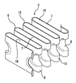
- FIG. 3 is a perspective view illustrating a fin member according to the first embodiment.
- (1) is a pipe member formed of an aluminum alloy, and as shown in FIG. 1, a plurality of straight pipe portions (2) are inserted into the fin member (3) at intervals ( 4), the end portion of the straight pipe portion (2) is curved, and this curved portion is a U-shaped folded portion (5).
- the pipe member (1) meandering in this way, the insertion interval (4) of the fin member (3) is preferably formed in parallel. And in each insertion space
- the outer diameter r of the pipe member (1) shown in FIG. 11 is 8 mm.
- the pipe member (1) is formed of an aluminum alloy. However, in other different embodiments, the pipe member (1) is made of steel, stainless steel, copper, copper alloy, It is also possible to form with titanium, titanium alloy or the like.
- the fin member (3) is formed of a flat strip made of an aluminum alloy having a plate thickness of 0.3 mm, and the strip is formed into a corrugated shape having a constant folding height as shown in FIG. It is a corrugated fin that has been bent into
- a large number of plate-like fins (7) are integrally formed via a curved portion (6) formed by bending.
- the arrangement interval (18) q of the fins (7) shown in FIG. 10 is 2.0 mm. Therefore, by forming the fin member (3) as described above, it becomes easy to arrange a large number of fins (7) on the pipe member (1) at equal intervals and in parallel, and the large number of fins (7).
- the surface area of the fin member (3) can be increased to easily produce a product having high heat exchange performance. Further, the presence of the curved portion (6) makes the fin member (3) three-dimensional and structurally stable and has an integrated structure, which improves the impact resistance and increases the durability of the heat exchanger (20). It becomes possible to improve.
- the fin member (3) is made of an aluminum alloy. However, in other different embodiments, the fin member (3) is made of steel, stainless steel, copper, a copper alloy, titanium, a titanium alloy, or the like. Is also possible.
- the curved top portion (15) that protrudes outwardly out of the curved portion (6) that is curved is pressed and deformed into a concave shape, thereby being shown in FIG.
- an arcuate engagement recess (8) is formed.
- the shape of the engaging recess (8) is such that the outer peripheral surface (10) of the pipe member (1) can be brought into surface contact with the outer peripheral surface (10) of the pipe member (1) as shown in FIGS. ).
- the heat exchanger (20) of the present embodiment has a simple configuration in which the fin member (3), which is a corrugated fin, is engaged with the pipe member (1) as described above, it is easy to manufacture. In addition to the large surface area of the fin member (3), the fin member (3) can efficiently dissipate heat from the pipe member (1), and the heat exchange performance can be easily enhanced. It is. Further, since the fin members (3) are arranged in parallel in one stage as shown in FIG. 1, unlike the two-stage heat exchanger described in Patent Document 1, the thickness of the heat exchanger (20) is different. It becomes possible to reduce the bulk of the direction. Therefore, the mountability in a narrow space such as under the floor of an automobile can be improved.
- the arrangement interval (18) q of the fin (7) is set to 2.0 mm, as shown in FIG. 8, the temperature drop of the pipe fluid that has passed through the heat exchanger (20) is reduced as compared with other arrangement intervals. It becomes possible to make it high, and a heat exchanger (20) excellent in heat exchange performance can be obtained.
- interval (17) t of the curve top part (15) in the protrusion part (16) from the pipe member (1) surface of the adjacent fin member (3) shown in FIG. 11 is 2 mm.
- the protrusion height L of the width direction of the fin member (3) from the pipe member (1) surface shown in FIG. 10 is 4 mm, Comprising: Relation with the opposing space
- interval (17) t 2mm of a curve top part (15).
- the stepping stone test was conducted in the heat exchanger (20) of the present example prepared as described above. This stepping stone test was carried out in accordance with the automobile standard JASO M 104 “Brake tube test method”, assuming that road stones are rolled up by wheels and come in contact with the vehicle while the vehicle is running.
- the test conditions of the stepping stone test of this example are as follows.
- Stepping stone Product name "GT” Model number "4" (Chipton Co., Ltd .: made of a chipton: substantially regular triangular prism having an edge portion and a side length of about 10 mm and a height of about 8 mm used for polishing work, or substantially regular three A truncated pyramid-shaped grinding stone)
- the engaging portion (22) between the fin member (3) and the pipe member (1) is not brazed, bonded, painted, or the like.
- the joint portion (22) and / or the vicinity thereof is brought into close contact between the fin member (3) and the pipe member (1) in the engagement portion (22) by means such as brazing, adhesion, or painting. May be.
- a gap is generated in the engaging portion (22), and moisture enters the gap. Since the situation where the fin member (3) and the pipe member (1) are corroded can be prevented, excellent corrosion resistance can be obtained in the engaging portion (22). Further, since the pipe member (1) and the fin member (3) are always kept in close contact with each other, heat exchange between the pipe member (1) and the fin member (3) can be performed efficiently, The exchange performance can be further improved.
Landscapes
- Engineering & Computer Science (AREA)
- Physics & Mathematics (AREA)
- Thermal Sciences (AREA)
- Mechanical Engineering (AREA)
- General Engineering & Computer Science (AREA)
- Geometry (AREA)
- Heat-Exchange Devices With Radiators And Conduit Assemblies (AREA)
Abstract
Description
η=tanh(mL)/mL m≡(2h/kδt)1/2×L
η:フィン効率(%)
k:熱伝導率(標準的なアルミ合金として約150w/mK)
h:熱伝達係数(曲げ平面垂直;約60w/m2K、曲げ平面平行;約25w/m2K)
L:フィン部材の突出高さ(mm)
δt:フィン部材の板厚(0.3mm)
にて計算を行った。この計算結果を基に作成したグラフを図2に示す。尚、上記フィン効率とは、フィン部材の形状、フィン部材の高さ、フィン部材の板厚により変化するフィン部材の放熱効率を意味するものであり、図2の結果は、フィン部材の形状、密度、及びフィン部材の板厚を一定とし、フィン部材の高さのみを3~13.5mmに変化させた場合のフィン効率の変化状況を表したものである。
(1)空気圧力;0.4±0.03MPa
(2)吹付角度;直角
(3)吹付距離;350mm
(4)飛石量;850g
(5)回数;5回
(6)試験装置;グラベロメーター
(7)飛石;花崗岩(玉砂利、大きさ9~15mm)
水の入口温度 70℃一定
空気流の入口温度 20℃一定
管内の水の流量 1.5~2.5L/min
空気流の流速 2.5~5.5m/s
軽油の入口温度 100℃
空気流の入口温度 50℃
軽油の流量 0.75L/min
空気流の流速 5m/sec
(1)空気圧力;0.4±0.03MPa
(2)吹付角度;直角
(3)吹付距離;350mm
(4)飛石量;850g
(5)回数;5回
(6)試験装置;グラベロメータ(スガ試験機株式会社製、JA400飛石試験機)
(7)飛石;品名「GT」型番「4」(株式会社チップトン製:エッジ部を有し、研磨作業で使用される一辺の長さ約10mmで高さ約8mmの略正三角柱状若しくは略正三角錐台状の研磨石)
2 直管部
3 フィン部材
5 折返し部
6 湾曲部
7 フィン
8 係合凹部
15 湾曲頂部
16 突出部分
17 対向間隔
18 配置間隔
Claims (3)
- 板材をコルゲート状に折曲加工してコルゲートフィンとするとともに、折曲加工により形成された湾曲部を凹状に押圧変形して係合凹部を形成した複数のフィン部材と、このフィン部材を介して複数の直管部を平行に配置するとともにこの直管部をU字状の折返し部で連結した蛇行状の管部材とから成り、この管部材の複数の直管部を、上記複数のフィン部材の係合凹部に係合した状態において、管部材の外径を8mm~12mmとし、隣接するフィン部材の湾曲部において最も外方に張り出した湾曲頂部の対向間隔を0.5~5.0mmとするとともに、上記直管部の表面からのフィン部材の突出高さを、11mm以下であって、且つ、上記対向間隔が0.5~5.0mmの範囲内において、y≧2.46x−0.29(y:管部材表面からのフィン部材の幅方向の突出高さ/湾曲頂部における対向間隔、x:湾曲頂部における対向間隔)の数式が成立する値としたことを特徴とする熱交換器。
- フィン部材は、板厚を0.2mm~0.5mmとしたことを特徴とする請求項1の熱交換器。
- フィン部材は、フィンの配置間隔を、1.6mm~2.2mmとしたことを特徴とする請求項1、または2の熱交換器。
Priority Applications (3)
| Application Number | Priority Date | Filing Date | Title |
|---|---|---|---|
| KR1020127015384A KR101698966B1 (ko) | 2010-02-04 | 2010-10-29 | 열교환기 |
| US13/577,343 US20130118724A1 (en) | 2010-02-04 | 2010-10-29 | Heat exchanger |
| EP10845251.7A EP2532998B1 (en) | 2010-02-04 | 2010-10-29 | Heat exchanger |
Applications Claiming Priority (2)
| Application Number | Priority Date | Filing Date | Title |
|---|---|---|---|
| JP2010-022997 | 2010-02-04 | ||
| JP2010022997A JP5393514B2 (ja) | 2010-02-04 | 2010-02-04 | 熱交換器 |
Publications (1)
| Publication Number | Publication Date |
|---|---|
| WO2011096120A1 true WO2011096120A1 (ja) | 2011-08-11 |
Family
ID=44355142
Family Applications (1)
| Application Number | Title | Priority Date | Filing Date |
|---|---|---|---|
| PCT/JP2010/069768 Ceased WO2011096120A1 (ja) | 2010-02-04 | 2010-10-29 | 熱交換器 |
Country Status (5)
| Country | Link |
|---|---|
| US (1) | US20130118724A1 (ja) |
| EP (1) | EP2532998B1 (ja) |
| JP (1) | JP5393514B2 (ja) |
| KR (1) | KR101698966B1 (ja) |
| WO (1) | WO2011096120A1 (ja) |
Cited By (2)
| Publication number | Priority date | Publication date | Assignee | Title |
|---|---|---|---|---|
| DE102017125054A1 (de) * | 2017-10-26 | 2019-05-02 | Miele & Cie. Kg | Wärmetauscher für ein Haushaltsgerät, wie beispielsweise einen Wäschetrockner, einen Geschirrspüler oder einen Waschtrockner mit einer Wärmepumpeneinrichtung |
| CN109708340A (zh) * | 2018-09-30 | 2019-05-03 | 合肥海尔电冰箱有限公司 | 一种蒸发器以及该蒸发器的使用方法 |
Families Citing this family (6)
| Publication number | Priority date | Publication date | Assignee | Title |
|---|---|---|---|---|
| KR101301801B1 (ko) * | 2011-10-18 | 2013-08-29 | 함승진 | 조립공정이 간편한 열 교환기 |
| JP6276539B2 (ja) * | 2013-08-26 | 2018-02-07 | 三菱重工業株式会社 | 熱交換器及び熱交換器の製造方法 |
| CN104089517B (zh) | 2014-07-18 | 2016-08-17 | 丹佛斯微通道换热器(嘉兴)有限公司 | 用于换热器的翅片和具有该翅片的换热器 |
| US10563930B2 (en) * | 2016-01-12 | 2020-02-18 | Hussmann Corporation | Heat exchanger including coil end close-off cover |
| JP6477920B2 (ja) * | 2016-09-29 | 2019-03-06 | Jfeスチール株式会社 | 熱交換器、ラジアントチューブ式加熱装置及び熱交換器の製造方法 |
| CN110715563A (zh) * | 2019-10-29 | 2020-01-21 | 广东吉荣核电设备暖通技术有限公司 | 一种具有较高换热效率的翅片式换热器 |
Citations (7)
| Publication number | Priority date | Publication date | Assignee | Title |
|---|---|---|---|---|
| JPH01181092A (ja) * | 1988-01-14 | 1989-07-19 | Nippon Denso Co Ltd | 熱交換器 |
| JPH06101982A (ja) * | 1992-09-18 | 1994-04-12 | Showa Alum Corp | 熱交換器 |
| JPH1144498A (ja) * | 1997-05-30 | 1999-02-16 | Showa Alum Corp | 熱交換器用偏平多孔チューブ及び同チューブを用いた熱交換器 |
| JP2000220982A (ja) * | 1999-01-27 | 2000-08-08 | Zexel Corp | 熱交換器 |
| JP2005201622A (ja) | 2003-12-15 | 2005-07-28 | Usui Kokusai Sangyo Kaisha Ltd | 熱交換器 |
| JP2009024896A (ja) * | 2007-07-17 | 2009-02-05 | Showa Denko Kk | 熱交換器 |
| JP2009229025A (ja) * | 2008-03-25 | 2009-10-08 | Showa Denko Kk | オイルクーラ |
Family Cites Families (6)
| Publication number | Priority date | Publication date | Assignee | Title |
|---|---|---|---|---|
| US2119761A (en) * | 1935-06-18 | 1938-06-07 | Clinton H Wentworth | Heat interchange device |
| US3275072A (en) * | 1964-08-14 | 1966-09-27 | Int Harvester Co | Radiator core guard |
| US3407874A (en) * | 1966-05-19 | 1968-10-29 | John R. Gier Jr. | Fin tube assemblage for heat exchangers |
| US4778004A (en) * | 1986-12-10 | 1988-10-18 | Peerless Of America Incorporated | Heat exchanger assembly with integral fin unit |
| JP2000130977A (ja) * | 1998-10-22 | 2000-05-12 | Hitachi Ltd | 冷蔵庫 |
| US6688380B2 (en) * | 2002-06-28 | 2004-02-10 | Aavid Thermally, Llc | Corrugated fin heat exchanger and method of manufacture |
-
2010
- 2010-02-04 JP JP2010022997A patent/JP5393514B2/ja active Active
- 2010-10-29 KR KR1020127015384A patent/KR101698966B1/ko not_active Expired - Fee Related
- 2010-10-29 US US13/577,343 patent/US20130118724A1/en not_active Abandoned
- 2010-10-29 WO PCT/JP2010/069768 patent/WO2011096120A1/ja not_active Ceased
- 2010-10-29 EP EP10845251.7A patent/EP2532998B1/en not_active Not-in-force
Patent Citations (7)
| Publication number | Priority date | Publication date | Assignee | Title |
|---|---|---|---|---|
| JPH01181092A (ja) * | 1988-01-14 | 1989-07-19 | Nippon Denso Co Ltd | 熱交換器 |
| JPH06101982A (ja) * | 1992-09-18 | 1994-04-12 | Showa Alum Corp | 熱交換器 |
| JPH1144498A (ja) * | 1997-05-30 | 1999-02-16 | Showa Alum Corp | 熱交換器用偏平多孔チューブ及び同チューブを用いた熱交換器 |
| JP2000220982A (ja) * | 1999-01-27 | 2000-08-08 | Zexel Corp | 熱交換器 |
| JP2005201622A (ja) | 2003-12-15 | 2005-07-28 | Usui Kokusai Sangyo Kaisha Ltd | 熱交換器 |
| JP2009024896A (ja) * | 2007-07-17 | 2009-02-05 | Showa Denko Kk | 熱交換器 |
| JP2009229025A (ja) * | 2008-03-25 | 2009-10-08 | Showa Denko Kk | オイルクーラ |
Non-Patent Citations (1)
| Title |
|---|
| See also references of EP2532998A4 |
Cited By (4)
| Publication number | Priority date | Publication date | Assignee | Title |
|---|---|---|---|---|
| DE102017125054A1 (de) * | 2017-10-26 | 2019-05-02 | Miele & Cie. Kg | Wärmetauscher für ein Haushaltsgerät, wie beispielsweise einen Wäschetrockner, einen Geschirrspüler oder einen Waschtrockner mit einer Wärmepumpeneinrichtung |
| DE102017125054B4 (de) * | 2017-10-26 | 2019-10-10 | Miele & Cie. Kg | Wärmetauscher für ein Haushaltsgerät, wie beispielsweise einen Wäschetrockner, einen Geschirrspüler oder einen Waschtrockner mit einer Wärmepumpeneinrichtung |
| CN109708340A (zh) * | 2018-09-30 | 2019-05-03 | 合肥海尔电冰箱有限公司 | 一种蒸发器以及该蒸发器的使用方法 |
| CN109708340B (zh) * | 2018-09-30 | 2021-01-05 | 合肥海尔电冰箱有限公司 | 一种蒸发器使用方法 |
Also Published As
| Publication number | Publication date |
|---|---|
| EP2532998B1 (en) | 2016-03-30 |
| US20130118724A1 (en) | 2013-05-16 |
| EP2532998A4 (en) | 2015-01-07 |
| JP2011163567A (ja) | 2011-08-25 |
| KR20120115267A (ko) | 2012-10-17 |
| EP2532998A1 (en) | 2012-12-12 |
| JP5393514B2 (ja) | 2014-01-22 |
| KR101698966B1 (ko) | 2017-01-23 |
Similar Documents
| Publication | Publication Date | Title |
|---|---|---|
| JP5393514B2 (ja) | 熱交換器 | |
| US9995539B2 (en) | Corrugated fins for heat exchanger | |
| JP2009063228A (ja) | 扁平状伝熱管 | |
| WO2012063443A1 (ja) | 熱交換器用チューブ | |
| JP5970924B2 (ja) | チューブを備えた熱交換器 | |
| JP2014034060A (ja) | 熱交換器管、熱交換器管組立体、及びそれらの製作方法 | |
| CN101010555A (zh) | 热交换器装置 | |
| JP2007278558A (ja) | 冷媒放熱器 | |
| CN100462660C (zh) | 热交换器 | |
| KR20140020700A (ko) | 열교환기 관, 열교환기 관조립체 및 그 제조 방법 | |
| JP4483536B2 (ja) | 熱交換器 | |
| US20080078538A1 (en) | Heat exchanger plate having integrated turbulation feature | |
| JP4932439B2 (ja) | プレートフィンチューブ熱交換器およびその製造方法 | |
| CN110785622A (zh) | 热交换器用管 | |
| CN103492827A (zh) | 制造用于热交换器的双鼻部管件的方法 | |
| CN110017703B (zh) | 热交换器 | |
| CN203704713U (zh) | 热交换器 | |
| US20070289728A1 (en) | Heat exchanger and mounting structure of the same | |
| CN103567732B (zh) | 换热器管、换热器管组件和制造它们的方法 | |
| CN205655718U (zh) | 用于散热器的水波纹翅片 | |
| JP5187047B2 (ja) | 熱交換器用チューブ | |
| KR101016696B1 (ko) | 턴핀형 열교환기 및 그의 제조방법 | |
| KR101560035B1 (ko) | 열교환기 관, 열교환기 관조립체 및 그 제조 방법 | |
| US8256502B2 (en) | Heat exchange member and heat exchange apparatus | |
| CN104006698B (zh) | 双弧斜断式翅片管无接触热阻传热元件 |
Legal Events
| Date | Code | Title | Description |
|---|---|---|---|
| 121 | Ep: the epo has been informed by wipo that ep was designated in this application |
Ref document number: 10845251 Country of ref document: EP Kind code of ref document: A1 |
|
| ENP | Entry into the national phase |
Ref document number: 20127015384 Country of ref document: KR Kind code of ref document: A |
|
| WWE | Wipo information: entry into national phase |
Ref document number: 6707/DELNP/2012 Country of ref document: IN |
|
| WWE | Wipo information: entry into national phase |
Ref document number: 1201003909 Country of ref document: TH |
|
| NENP | Non-entry into the national phase |
Ref country code: DE |
|
| WWE | Wipo information: entry into national phase |
Ref document number: 2010845251 Country of ref document: EP |
|
| WWE | Wipo information: entry into national phase |
Ref document number: 13577343 Country of ref document: US |