WO2011096274A1 - スクリューロータ加工用工作機械とこれを用いたスクリューロータ加工方法 - Google Patents
スクリューロータ加工用工作機械とこれを用いたスクリューロータ加工方法 Download PDFInfo
- Publication number
- WO2011096274A1 WO2011096274A1 PCT/JP2011/050855 JP2011050855W WO2011096274A1 WO 2011096274 A1 WO2011096274 A1 WO 2011096274A1 JP 2011050855 W JP2011050855 W JP 2011050855W WO 2011096274 A1 WO2011096274 A1 WO 2011096274A1
- Authority
- WO
- WIPO (PCT)
- Prior art keywords
- tool
- axis
- screw rotor
- machining
- screw
- Prior art date
- Legal status (The legal status is an assumption and is not a legal conclusion. Google has not performed a legal analysis and makes no representation as to the accuracy of the status listed.)
- Ceased
Links
Images






Classifications
-
- B—PERFORMING OPERATIONS; TRANSPORTING
- B23—MACHINE TOOLS; METAL-WORKING NOT OTHERWISE PROVIDED FOR
- B23F—MAKING GEARS OR TOOTHED RACKS
- B23F15/00—Methods or machines for making gear wheels of special kinds not covered by groups B23F7/00 - B23F13/00
- B23F15/08—Making intermeshing rotors, e.g. of pumps
-
- F—MECHANICAL ENGINEERING; LIGHTING; HEATING; WEAPONS; BLASTING
- F04—POSITIVE - DISPLACEMENT MACHINES FOR LIQUIDS; PUMPS FOR LIQUIDS OR ELASTIC FLUIDS
- F04C—ROTARY-PISTON, OR OSCILLATING-PISTON, POSITIVE-DISPLACEMENT MACHINES FOR LIQUIDS; ROTARY-PISTON, OR OSCILLATING-PISTON, POSITIVE-DISPLACEMENT PUMPS
- F04C18/00—Rotary-piston pumps specially adapted for elastic fluids
- F04C18/08—Rotary-piston pumps specially adapted for elastic fluids of intermeshing-engagement type, i.e. with engagement of co-operating members similar to that of toothed gearing
- F04C18/12—Rotary-piston pumps specially adapted for elastic fluids of intermeshing-engagement type, i.e. with engagement of co-operating members similar to that of toothed gearing of other than internal-axis type
- F04C18/14—Rotary-piston pumps specially adapted for elastic fluids of intermeshing-engagement type, i.e. with engagement of co-operating members similar to that of toothed gearing of other than internal-axis type with toothed rotary pistons
- F04C18/16—Rotary-piston pumps specially adapted for elastic fluids of intermeshing-engagement type, i.e. with engagement of co-operating members similar to that of toothed gearing of other than internal-axis type with toothed rotary pistons with helical teeth, e.g. chevron-shaped, screw type
-
- F—MECHANICAL ENGINEERING; LIGHTING; HEATING; WEAPONS; BLASTING
- F04—POSITIVE - DISPLACEMENT MACHINES FOR LIQUIDS; PUMPS FOR LIQUIDS OR ELASTIC FLUIDS
- F04C—ROTARY-PISTON, OR OSCILLATING-PISTON, POSITIVE-DISPLACEMENT MACHINES FOR LIQUIDS; ROTARY-PISTON, OR OSCILLATING-PISTON, POSITIVE-DISPLACEMENT PUMPS
- F04C2230/00—Manufacture
- F04C2230/10—Manufacture by removing material
-
- F—MECHANICAL ENGINEERING; LIGHTING; HEATING; WEAPONS; BLASTING
- F04—POSITIVE - DISPLACEMENT MACHINES FOR LIQUIDS; PUMPS FOR LIQUIDS OR ELASTIC FLUIDS
- F04C—ROTARY-PISTON, OR OSCILLATING-PISTON, POSITIVE-DISPLACEMENT MACHINES FOR LIQUIDS; ROTARY-PISTON, OR OSCILLATING-PISTON, POSITIVE-DISPLACEMENT PUMPS
- F04C2240/00—Components
- F04C2240/20—Rotors
-
- F—MECHANICAL ENGINEERING; LIGHTING; HEATING; WEAPONS; BLASTING
- F04—POSITIVE - DISPLACEMENT MACHINES FOR LIQUIDS; PUMPS FOR LIQUIDS OR ELASTIC FLUIDS
- F04C—ROTARY-PISTON, OR OSCILLATING-PISTON, POSITIVE-DISPLACEMENT MACHINES FOR LIQUIDS; ROTARY-PISTON, OR OSCILLATING-PISTON, POSITIVE-DISPLACEMENT PUMPS
- F04C25/00—Adaptations of pumps for special use of pumps for elastic fluids
- F04C25/02—Adaptations of pumps for special use of pumps for elastic fluids for producing high vacuum
Definitions
- the present invention relates to a screw rotor machining machine tool and a screw rotor machining method using the same, and more particularly to a screw rotor machining machine tool for machining a screw rotor having unequal lead and unequal inclination angles and a screw rotor using the same. It relates to a processing method.
- a gas working chamber is configured by a pair of male and female screw rotors that mesh with each other and a stator that houses both screw rotors, and a gas intake air is connected to one end and the other end of the working chamber.
- a device provided with a mouth and a discharge port is known.
- the spindle driving device that rotationally drives the workpiece spindle, the tool post to which the tool for machining the workpiece is attached, and the tool post perpendicular to the workpiece spindle
- a turret driving device for driving in any direction a spindle control device and a numerical control device for controlling the turret driving device, and a switchable operation with the spindle driving device to rotate the spindle of the workpiece.
- a cutter axis for rotating the rotary blade at a position where the rotary blade can contact the screw lead, and a tool rest on which the cutter axis is installed
- a ⁇ -axis that rotates the workpiece which is a screw generating material
- a Y-axis that moves the tool post and the workpiece relative to each other in the normal direction from the center of the workpiece
- a tool post in the axial direction of the workpiece A screw processing machine having an X axis for moving the workpiece and the workpiece relative to each other and a ⁇ axis for changing the screw lead angle by turning the tool post on which the cutter axis is installed, and capable of simultaneously controlling at least the ⁇ axis and the X axis. It is known (for example, refer to Patent Document 2).
- the shape of the cross section perpendicular to the shaft is the same, and the same diameter from the suction end to the discharge end along the axial direction. It has a multi-turn screw, and the screw is an uneven lead with a lead that gradually becomes denser from the suction end toward the discharge end, and an equal lead with a tight lead with respect to the suction end side screw.
- a screw-type vacuum pump comprising a suction end side screw part and a discharge end side screw part formed separately from each other (for example, a patent document) 3).
- the conventional screw rotor processing apparatus described in Patent Document 1 does not cause a problem when processing a screw rotor having an inclined angle such as an equal lead, but means for adjusting the rake angle between the cutting tool and the workpiece. Therefore, when machining a screw rotor with an unequal lead unequal inclination angle, the cutting tool cannot be brought into contact with the workpiece at an appropriate rake angle, and the unequal lead unequal inclination angle There is a problem that it is difficult to process a screw rotor having a high accuracy.
- the tool rest on which the tool shaft is installed has a ⁇ axis that changes the screw lead angle, so that the tool rest is centered on the ⁇ axis.
- the conventional screw type vacuum pump described in Patent Document 3 is obtained by machining the suction lead side screw portion having a rough lead and the dense discharge end side screw portion of the lead into separate bodies with appropriate blades. In this case, the connection work between the suction end side screw portion and the discharge end side screw portion is still overcome.
- any solution is presented. It was not a thing.
- the present invention solves the conventional problems. That is, the object of the present invention is to avoid unequal lead inaccurate at a low cost and in a short time without requiring a large processing burden.
- the screw rotor machining machine tool of the present invention is a screw rotor machining machine tool for machining a screw rotor having unequal lead and unequal inclination angles, and a main shaft for holding a workpiece, and the main shaft can be freely rotated.
- the tool is rotated with respect to the tool base in accordance with the Y axis for moving the tool on a line intersecting the C axis, and the lead angle of the screw rotor, and the rake angle of the tool with respect to the workpiece is adjusted.
- a axis and the main axis By the rotation of the rotation and the tool table movement and the tool numerical control to and a numerical control means for synchronizing is obtained by solving the problems described above.
- the screw rotor processing method of this invention is a screw which processes the screw rotor which has an unequal lead unequal inclination angle using the machine tool for screw rotor processing of any one of Claim 1 thru
- a rotor machining method, a tool moving step for moving the tool rest and tool along the X axis, Y axis and Z axis, a main shaft rotating step for rotating the main shaft about the C axis, and the screw By performing an angle adjustment step by the A axis that adjusts the rake angle of the tool with respect to the workpiece by rotating the tool about the X axis with respect to the tool table according to the lead angle of the rotor, as described above. It solves the problem.
- the screw type vacuum pump according to the present invention includes the screw rotor processed by the screw rotor processing method according to any one of claims 4 to 9 in a pair of males and females. It solves the problem.
- the screw-type vacuum pump 100 includes a stator 110 having a discharge port 111 and an intake port 112 and a pair of male and female screws disposed in mesh with each other in the stator 110.
- the rotors 120a and 120b, the bearing unit 130 attached to the stator 110 and bearing both ends of the rotor rotation shaft 121 of the screw rotor 120, and the rotation of the pair of screw rotors 120 attached to one end of the rotor rotation shaft 121 are synchronized.
- a shaft seal 150 that prevents the lubricating oil supplied to the timing gear 140 and the bearing portion 130 from entering the gas working chamber.
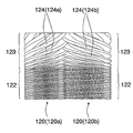
- each screw rotor 120a, 120b includes an equal lead portion 122 disposed on the discharge port 111 side of the stator 110 and an unequal lead portion disposed on the intake port 112 side of the stator 110. 123, respectively.
- the equal lead portion 122 is formed with an equal lead equal inclination angle and has straight tooth traces.
- the unequal lead portion 123 is formed so that the lead and the inclination angle gradually decrease from the intake port 112 side to the discharge port 111 side, and has curved tooth traces. ing.
- the cross-sectional shape perpendicular to the axis also changes.
- each screw rotor 120a, 120b is designed to obtain a large exhaust speed regardless of the molecular weight by increasing the intake conductance on the intake port 112 side.
- the mutual spacing between the screw teeth 124a and 124b of the pair of male and female screw rotors 120a and 120b, that is, the meshing gap, is independent of changes in the lead and inclination angle of the screw rotor 120, as shown in FIGS. Further, it is formed so as to be always constant from the intake port 112 side to the discharge port 111 side.
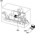
- the screw rotor machining machine tool 200 includes a spindle 211 that holds a workpiece W, a spindle base 210 that rotatably supports the spindle 211, a spindle base 210, and a spindle 211.
- the tool base 220 that is movable with respect to the tool base 220, the C axis that rotates the spindle 211 with respect to the spindle base 210, and the tool 221 for the workpiece W that is orthogonal to the C axis.
- the Z-axis that moves the tool table 220 perpendicular to the X-axis and parallel to the C-axis According to the Y axis to be moved, the B axis when the tool table 220 and the tool 221 are turned to form an undercut in the cross section perpendicular to the axis of the screw rotor 120, and the lead angle of the screw rotor 120.
- the A axis that adjusts the rake angle of the tool 221 relative to the workpiece W by rotating the tool 221 with respect to the tool base 220, the rotation of the spindle 211, the movement of the tool base 220, and the rotation of the tool 221 are numerically controlled and synchronized. And a numerical control means 230 for making it possible.
- the main shaft 211 is designed to rotate around the C axis that coincides with the main shaft 211 with respect to the main shaft 210.
- the tool table 220 is designed to be movable along the X axis, the Y axis, and the Z axis, and is designed so that the B axis can pivot about the Y axis. ing.
- the tool 221 is designed to have an A axis so as to rotate with respect to the tool table 220 about the X axis that coincides with the axis of the tool 221.
- the screw rotor machining machine tool 200 is a three-dimensional measuring means including a measurement probe that generates a measurement value by measuring the shape of the screw rotor 120 during or after machining. 240, a numerical value comparison means 250 that generates a correction value by comparing the measured value with the three-dimensional model of the screw rotor, and a correction value output means 260 that outputs the correction value to the numerical control means 230. I have.
- the numerical value comparison means 250 and the correction value output means 260 are constituted by a personal computer terminal connected to the screw rotor machining machine tool 200 as shown in FIG.
- the machine 200 itself may be provided with the numerical value comparison means 250 and the correction value output means 260.
- the X axis, the Y axis, the Z axis, the C axis, and the B axis are used, that is, the X axis.
- the first undercut forming process in the case of forming the undercut in the cross section perpendicular to the axis of the screw rotor 120 by turning the table 220 and the tool 221 is executed by numerical control by the numerical control means 230.
- the first tool moving step, the first spindle rotating step, and the forming step in the case of forming the first undercut are executed simultaneously or individually according to the shape of the equal lead portion 122.
- the X axis, the Y axis, the Z axis, the C axis, the B axis, and the A axis are A second tool moving step of moving the tool table 220 and the tool 221 along the X axis, the Y axis, and the Z axis, and a second spindle rotating step of rotating the main shaft 211 around the C axis.
- the second tool moving step, the second spindle rotating step, the second undercut forming step when forming the second undercut, and the angle adjusting step are performed according to the shape of the unequal lead portion 123. Executed simultaneously or separately.
- the rake angle, clearance angle, blade angle, etc. between the tool 221 and the rake surface (machined surface) of the workpiece W are calculated to obtain the workpiece W
- the tool 121 is brought into contact with an appropriate rake angle.
- the tooth tip 221a of the tool 221 is made parallel to the C axis and brought into contact with the workpiece W.
- a measuring step for measuring the shape during or after the processing using the three-dimensional measuring means 240 comprising a measuring probe and generating a measured value
- a comparison step of comparing the three-dimensional model of the screw rotor 120 and generating a correction value using the numerical value comparison means 250, and an output step of outputting the correction value to the numerical control means 230 using the correction value output means 260 Perform further.
- the processing accuracy of the screw rotor 120 can be improved by performing these steps once or a plurality of times during or after the processing of the screw rotor 120.
- the tool table 220 and the tool 221 are turned to form a B axis that forms an undercut in the cross section perpendicular to the axis of the screw rotor 120, and the tool table according to the lead angle of the screw rotor 120.
- the configuration of the modification other than the screw rotor 320 that is, the configuration of the screw type vacuum pump 100 and the screw rotor machining machine tool 200 is exactly the same as that of the above-described embodiment.
- the screw type vacuum pump 100 and the screw rotor machining machine tool 200 are denoted by the same reference numerals, and description thereof is omitted.
- the screw rotor 320 of this modification is installed in a pair of males and females in the stator 110 of the screw type vacuum pump 100.
- each screw rotor 320 includes an equal lead portion 322 disposed on the discharge port 111 side of the stator 110, an equal lead portion 327 disposed on the intake port 112 side of the stator 110, and these equal leads.
- the non-uniform lead portion 323 is disposed between the portion 322 and the equal lead portion 327.
- the lead and the inclination angle of the equal lead portion 327 are set larger than the lead and the inclination angle of the equal lead portion 322.
- the equal lead portion 322 is formed with an equal lead equal inclination angle and has straight tooth traces.
- the unequal lead portion 323 is formed so that the lead and the inclination angle gradually decrease from the intake port 112 side to the discharge port 111 side. have.
- the equal lead portion 327 is formed with an equal lead equal inclination angle and has a straight tooth trace.
- the tooth traces of the equal lead portion 322, the unequal lead portion 323, and the equal lead portion 327 are connected in a tangential manner as shown in FIGS.
- the screw rotor 320 is designed so as to obtain a large exhaust speed regardless of the molecular weight by increasing the intake conductance on the intake port 112 side.
- the mutual distance between the screw teeth 324 of the pair of male and female screw rotors 320 is always constant from the intake port 112 side to the discharge port 111 side regardless of changes in the lead and inclination angle of the screw rotor 320. It is formed as follows.
- the processing method of the equal lead portion 322 and the unequal lead portion 323 of the screw rotor 320 according to this modification is the same as the processing method of the equal lead portion 122 and the unequal lead portion 123 of the screw rotor 120 described above. Therefore, the description thereof is omitted.
- the processing method of the equal lead portion 327 of the screw rotor 320 of the present modification is the same as that of the equal lead portion 322 except for the lead and the inclination angle.
- the first undercut forming process in the case of forming the undercut in the cross section perpendicular to the axis of the screw rotor 120 by turning is executed by numerical control by the numerical control means 230.
- the first tool moving step, the first spindle rotating step, and the forming step when forming the first undercut are executed simultaneously or individually according to the shape of the equal lead portion 327.
- SYMBOLS 100 Screw type vacuum pump 110 ... Stator 111 ... Discharge port 112 ... Intake port 120, 320 ... Screw rotor 121 ... Rotor rotating shaft 122, 322 ... Equal lead part 123 323 ... Unequal lead part 124, 324 ... Screw tooth 125 ... Tooth surface 126, 326 ... Tooth bottom 327 ... Equivalent lead part 130 ... Bearing part 140 ... Timing gear DESCRIPTION OF SYMBOLS 150 ... Shaft sealing part 200 ... Machine tool for screw rotor processing 210 ... Spindle table 211 ... Spindle 220 ... Tool table 221 ... Tool 230 ... Numerical control means 240 ... Three-dimensional measuring means 250 ... Numerical value comparing means 260 ... Correction Output means W ⁇ workpiece
Landscapes
- Engineering & Computer Science (AREA)
- Mechanical Engineering (AREA)
- Applications Or Details Of Rotary Compressors (AREA)
- Gear Processing (AREA)
Abstract
多大な加工負担を必要とすることなく、低コストで短時間にて高精度な不等リード不等傾斜角を有するスクリューロータを大量に加工することが可能であり、スクリュー型真空ポンプを安価にかつ大量に供給することを可能にするスクリューロータ加工用工作機械とこれを用いたスクリューロータ加工方法を提供すること。 主軸211と、主軸台210と、工具台220と、工具221と、主軸211の回転軸であるC軸と、工具台220の移動方法であるX軸およびZ軸およびY軸と、スクリューロータ120のリード角に応じて工具221を回転させて被加工物Wに対する工具221のすくい角を調節するA軸と、数値制御手段230とを備えているスクリューロータ加工用工作機械200とこれを用いたスクリューロータ加工方法。
Description
本発明は、スクリューロータ加工用工作機械とこれを用いたスクリューロータ加工方法に関し、特に、不等リード不等傾斜角を有するスクリューロータを加工するスクリューロータ加工用工作機械とこれを用いたスクリューロータ加工方法に関する。
一般に、スクリュー型真空ポンプとして、互いに噛み合う雌雄一対のスクリューロータと、両スクリューロータを収納するステータとにより気体作動室を構成し、この作動室の一端部および他端に連通するように気体の吸気口および吐出口とを設けたものが知られている。
スクリュー型真空ポンプに用いられるスクリューロータとして、ねじれ角が、当該ねじれの進行に伴って連続的に変化するように不等リード不等傾斜角としたものが、注目されている。
そして、このような不等リード不等傾斜角を有するスクリューロータを備えたスクリュー型真空ポンプの安価かつ大量の供給が求められているが、従来は、エンドミル等の回転工具を用いて切削加工していたので、1本のロータを加工するのに約7日間も必要としていた。
しかも、このようなエンドミル等の回転工具を用いた切削加工では、削りカスが除去し難い、工具が折れやすく消耗が激しく、加工精度が不安定になる等の問題もあり、安価に製造するのが難しかった。
また、従来の等リード等傾斜角のスクリューロータの加工装置として、ワークの主軸を回転駆動する主軸駆動装置と、このワークを加工する刃具を取り付ける刃物台と、この刃物台をワークの主軸に直角な方向に駆動する刃物台駆動装置と、主軸駆動装置と前記刃物台駆動装置とを制御する数値制御装置とを備え、主軸駆動装置と切り換え可能に作動し、ワークの主軸を回転駆動する第2の主軸駆動装置を設けた加工装置が知られている(例えば、特許文献1参照。)。
また、不等リード不等傾斜角を有するスクリューロータを加工する従来のスクリュー加工機として、回転刃がスクリューリードに接しうる位置で回転刃を回転させる刃物軸と、刃物軸を設置した刃物台と、スクリュー創成材料である被加工物を回転させるω軸と、被加工物の中心から法線方向に刃物台と被加工物とを相対移動させるY軸と、被加工物の軸方向に刃物台と被加工物とを相対移動させるX軸と、刃物軸を設置した刃物台を回してスクリューリード角を変えるθ軸と、を有し、少なくともω軸およびX軸を同時に制御できるスクリュー加工機が知られている(例えば、特許文献2参照。)。
このスクリュー加工機を用いた具体的な加工方法では、それぞれ異なる刃物を用いた2つの加工段階、すなわち、スクリューロータの溝断面とほぼ同形状を有する総形回転刃物(砥石)による粗加工と、厚さの薄い回転刃物(砥石)による仕上げ加工の2つの加工段階でスクリューロータを加工している。
また、不等リード不等傾斜角を有するスクリューロータを備えた従来のスクリュー型真空ポンプとして、軸に対し垂直断面の形状が同一であり、軸方向に沿って吸入エンドから吐出エンドまで同一径である多数巻のスクリューを備え、スクリューは、吸入エンドから吐出エンド側に向けて漸次リードが密となる不等リードの吸入エンド側スクリュー部と、吸入エンド側スクリュー部に対しリードが密な等リードの吐出エンド側スクリュー部とを備え、これら別体で形成された吸入エンド側スクリュー部と吐出エンド側スクリュー部とを相互に結合してなるスクリュー型真空ポンプが知られている(例えば、特許文献3参照。)。
ところが、特許文献1に記載された従来のスクリューロータの加工装置では、等リード等傾斜角のスクリューロータを加工する際には問題を生じないが、刃具とワークとの間のすくい角の調整手段を有していないため、不等リード不等傾斜角を有するスクリューロータを加工する際に、適切なすくい角でワークに対して刃具を当接させることができず、不等リード不等傾斜角を有するスクリューロータを高精度に加工するのが難しいという問題があった。
また、特許文献2に記載された従来のスクリュー加工機では、刃物軸を設置した刃物台を回してスクリューリード角を変えるθ軸を有していることにより、このθ軸を中心として刃物台を旋回させることで、不等リード不等傾斜角を有するスクリューロータの大まかな外形を形成することは可能であるものの、単一の回転刃(フライス)を用いてスクリューロータのスクリュー歯の捻れを高精度には加工することができず、スクリューロータを高精度に加工するためには、荒加工と仕上げ加工との2つの加工段階を必要とし、多大な加工負担および加工時間を要するという問題があった。
また、特許文献3に記載された従来のスクリュー型真空ポンプは、リードの粗い吸入エンド側スクリュー部とリードの密な吐出エンド側スクリュー部を夫々に適した刃物で別体に機械加工してこれらを結合することで、不等リード不等傾斜角を有するスクリューロータの機械加工の困難さを克服しているが、この場合でもやはり、吸入エンド側スクリュー部と吐出エンド側スクリュー部との結合作業に多大な労力を必要とするという問題があり、また、ねじれの進行に伴って連続的に変化する不等リード不等傾斜角を有するスクリューロータの加工方法としては、何らの解決手段を提示するものではなかった。
そこで、本発明は、従来の問題を解決するものであって、すなわち、本発明の目的は、多大な加工負担を必要とすることなく、低コストで短時間にて高精度な不等リード不等傾斜角を有するスクリューロータを大量に加工することが可能であり、スクリュー型真空ポンプを安価にかつ大量に供給することを可能にするスクリューロータ加工用工作機械とこれを用いたスクリューロータ加工方法を提供することである。
本発明のスクリューロータ加工用工作機械は、不等リード不等傾斜角を有するスクリューロータを加工するスクリューロータ加工用工作機械であって、被加工物を保持する主軸と、該主軸を回転自在に支持する主軸台と、該主軸台および主軸に対して移動自在な工具台と、該工具台により支持される工具と、前記主軸台に対して主軸を回転させるC軸と、該C軸に直交して前記被加工物に対する工具の切り込み方向を規定するX軸と、該X軸に直交して前記C軸に対して平行に工具台を移動させるZ軸と、前記X軸およびZ軸に直交して前記工具をC軸に交差する線上に移動させるY軸と、前記スクリューロータのリード角に応じて前記工具台に対して工具を回転させて前記被加工物に対する工具のすくい角を調節するA軸と、前記主軸の回転および工具台の移動および工具の回転を数値制御して同期させる数値制御手段とを備えていることにより、前述した課題を解決したものである。
また、本発明のスクリューロータ加工方法は、請求項1乃至請求項3のいずれか1項に記載のスクリューロータ加工用工作機械を用いて不等リード不等傾斜角を有するスクリューロータを加工するスクリューロータ加工方法であって、前記X軸およびY軸およびZ軸に沿って前記工具台および工具を移動させる工具移動工程と、前記C軸を中心に前記主軸を回転させる主軸回転工程と、前記スクリューロータのリード角に応じて前記工具台に対して工具をX軸を中心に回転させて前記被加工物に対する工具のすくい角を調節するA軸による角度調整工程とを実行することにより、前述した課題を解決したものである。
また、本発明のスクリュー型真空ポンプは、請求項4乃至請求項9のいずれかに1項に記載のスクリューロータ加工方法で加工されたスクリューロータを雄雌一対で備えていることにより、前述した課題を解決したものである。
本発明によれば、多大な加工負担を必要とすることなく、低コストで短時間にて高精度な不等リード不等傾斜角を有するスクリューロータを大量に加工することができ、スクリュー型真空ポンプを安価にかつ大量に供給することができる。
以下、本発明の一実施例を図面に基づいて説明する。
まず、スクリュー型真空ポンプ100は、図1および図2に示すように、吐出口111および吸気口112を有するステータ110と、このステータ110内に相互に噛み合った状態で配置される雌雄一対のスクリューロータ120a、120bと、ステータ110に取り付けられてスクリューロータ120のロータ回転軸121の両端を軸受する軸受部130と、ロータ回転軸121の一端部に取り付けられて一対のスクリューロータ120の回転を同期させるタイミングギア140と、タイミングギア140および軸受部130に供給された潤滑油の気体作動室内への侵入を阻止する軸封部150とを備えている。
各スクリューロータ120a、120bは、図3乃至図6に示すように、ステータ110の吐出口111側に配置された等リード部122と、ステータ110の吸気口112側に配置された不等リード部123とからそれぞれ構成されている。
等リード部122は、図6などに示すように、等リード等傾斜角で形成されて、直線の歯筋を有している。
また、不等リード部123は、図6などに示すように、吸気口112側から吐出口111側に向けてリードおよび傾斜角が漸次小さくなるように形成されて、曲線の歯筋を有している。
そして、これら等リード部122と不等リード部123の歯筋は、図6などに示すように、接線状に繋がっている。
また、不等リード部123では、軸直角断面形状も変化している。
このように、各スクリューロータ120a、120bは、吸気口112側の取込みコンダクタンスを大きくすることにより分子量の大小に関係無く大きな排気速度を得るように設計されている。
そして、これら雌雄一対のスクリューロータ120a、120bのスクリュー歯124a、124bの相互間隔、すなわち、噛合隙間は、図3および図5に示すように、スクリューロータ120のリードおよび傾斜角の変化に関わりなく、吸気口112側から吐出口111側にかけて常に一定になるように形成されている。
スクリューロータ加工用工作機械200は、図7乃至図9に示すように、被加工物Wを保持する主軸211と、主軸211を回転自在に支持する主軸台210と、主軸台210および主軸211に対して移動自在な工具台220と、工具台220により支持される工具221と、主軸台210に対して主軸211を回転させるC軸と、C軸に直交して被加工物Wに対する工具221の切り込み方向を規定するX軸と、X軸に直交してC軸に対して平行に工具台220を移動させるZ軸と、X軸およびZ軸に直交して工具221をC軸に交差する線上に移動させるY軸と、工具台220および工具221を旋回させてスクリューロータ120の軸直角断面にアンダーカットを形成する場合のB軸と、スクリューロータ120のリード角に応じて工具台220に対して工具221を回転させて被加工物Wに対する工具221のすくい角を調節するA軸と、主軸211の回転および工具台220の移動および工具221の回転を数値制御して同期させる数値制御手段230とを備えている。
すなわち、主軸211は、図7乃至図9に示すように、主軸台210に対して主軸211の軸線に一致するC軸を中心に回転するように設計されている。
また、工具台220は、図7乃至図9に示すように、X軸とY軸とZ軸に沿って移動自在に設計されているとともに、Y軸を中心としてB軸を旋回自在に設計されている。
そして、工具221は、図7乃至図9に示すように、工具221の軸線に一致するX軸を中心として、工具台220に対して回転するようにA軸が設計されている。
そして、スクリューロータ加工用工作機械200は、図8および図10に示すように、スクリューロータ120の加工中または加工終了後の形状を計測して測定値を生成する測定プローブからなる三次元測定手段240と、測定値とスクリューロータの三次元モデルとを比較して修正値を生成する数値比較手段250と、修正値を数値制御手段230に出力する修正値出力手段260とを含む制御システムを更に備えている。
本実施例では、数値比較手段250と修正値出力手段260は、図8に示すように、スクリューロータ加工用工作機械200にLAN接続されたパソコン端末により構成されているが、スクリューロータ加工用工作機械200自体に数値比較手段250および修正値出力手段260を設けても何ら構わない。
つぎに、スクリューロータ加工用工作機械200を用いてスクリューロータ120を加工するスクリューロータ加工方法を説明する。
まず、スクリューロータ120の等リード等傾斜角で形成された等リード部122を加工する際には、X軸、Y軸、Z軸、C軸、および、B軸を利用し、すなわち、X軸およびY軸およびZ軸に沿って工具台220および工具221を移動させる第1の工具移動工程と、C軸を中心に主軸211を回転させる第1の主軸回転工程と、B軸を中心に工具台220および工具221を旋回させてスクリューロータ120の軸直角断面にアンダーカットを形成する場合の第1のアンダーカット形成工程とを数値制御手段230により数値制御して実行する。
これら第1の工具移動工程、第1の主軸回転工程、および、第1のアンダーカットを形成する場合の形成工程は、等リード部122の形状に応じて、同時または個別に実行される。
つぎに、スクリューロータ120の不等リード不等傾斜角で形成された不等リード部123を加工する際には、X軸、Y軸、Z軸、C軸、B軸、および、A軸を利用し、すなわち、X軸およびY軸およびZ軸に沿って工具台220および工具221を移動させる第2の工具移動工程と、C軸を中心に主軸211を回転させる第2の主軸回転工程と、B軸を中心に工具台220および工具221を旋回させてスクリューロータ120の軸直角断面にアンダーカットを形成する場合の第2のアンダーカット形成工程と、スクリューロータ120のリード角に応じて工具台220に対して工具221をX軸を中心にA軸を回転させて被加工物Wに対する工具221のすくい角を調節する角度調整工程とを数値制御手段230により数値制御して実行する。
これら第2の工具移動工程、第2の主軸回転工程、第2のアンダーカットを形成する場合の第2のアンダーカット形成工程、および、角度調整工程は、不等リード部123の形状に応じて、同時または個別に実行される。
スクリューロータ120の歯面125を切削する際には、工具221と被加工物Wのすくい面(加工面)との間のすくい角、逃げ角、刃物角等を計算し、被加工物Wに対して工具121を適切なすくい角で当接させる。
また、スクリューロータ120の歯底126を切削する際には、C軸に対して工具221の歯先221aを平行にして、被加工物Wに対して当接させる。
そして、スクリューロータ120の加工中または加工終了後に、測定プローブからなる三次元測定手段240を用いて加工中または加工終了後の形状を計測して測定値を生成する測定工程と、この測定値とスクリューロータ120の三次元モデルとを比較して修正値を数値比較手段250を用いて生成する比較工程と、修正値を修正値出力手段260を用いて数値制御手段230に出力する出力工程とを更に実行する。
これらの工程をスクリューロータ120の加工中または加工終了後に1回または複数回行うことにより、スクリューロータ120の加工精度を向上させることができる。
このようにして得られた本実施例では、工具台220および工具221を旋回させてスクリューロータ120の軸直角断面にアンダーカットを形成するB軸と、スクリューロータ120のリード角に応じて工具台220に対して工具221を回転させて被加工物Wに対する工具221のすくい角を調節するA軸とを備えていることにより、加工途中における工具交換などを必要とすることなく、低コストで短時間にて高精度な不等リード不等傾斜角を有するスクリューロータ120を大量に加工することができ、スクリュー型真空ポンプ100を安価にかつ大量に供給することができる。
そして、このように、スクリューロータ120を高精度に加工することにより、このスクリューロータ120を雌雄一対でスクリュー型真空ポンプ100内に配置した際に、スクリュー歯124の噛合隙間が吸気口112側から吐出口111側にかけて常に一定になるため、スクリュー型真空ポンプ100の圧縮比を著しく向上できる。
つぎに、スクリューロータの一変形例について、図11および図12に基づいて説明する。
ここで、本変形例のスクリューロータ320以外の構成、すなわち、スクリュー型真空ポンプ100およびスクリューロータ加工用工作機械200の構成に関しては、前述した実施例と全く同じであり、図1乃至図10に示したスクリュー型真空ポンプ100およびスクリューロータ加工用工作機械200と同様の構成を有している。
そのため、スクリュー型真空ポンプ100およびスクリューロータ加工用工作機械200には、同一の参照符号を付し、これらの説明は省略する。
本変形例のスクリューロータ320は、スクリュー型真空ポンプ100のステータ110内に雌雄一対で設置されるものである。
各スクリューロータ320は、図11に示すように、ステータ110の吐出口111側に配置される等リード部322と、ステータ110の吸気口112側に配置される等リード部327と、これら等リード部322と等リード部327との間に配置される不等リード部323とから構成されている。
図11および図12に示すように、等リード部327のリードおよび傾斜角は、等リード部322のリードおよび傾斜角より、大きく設定されている。
等リード部322は、図11および図12に示すように、等リード等傾斜角で形成されて、直線の歯筋を有している。
また、不等リード部323は、図11および図12などに示すように、吸気口112側から吐出口111側に向けてリードおよび傾斜角が漸次小さくなるように形成されて、曲線の歯筋を有している。
また、等リード部327は、図11および図12に示すように、等リード等傾斜角で形成されて、直線の歯筋を有している。
そして、これら等リード部322と不等リード部323と等リード部327の歯筋は、図11および図12に示すように、接線状に繋がっている。
また、不等リード部323では、軸直角断面形状も変化している。
このように、スクリューロータ320は、吸気口112側の取込みコンダクタンスを大きくすることにより分子量の大小に関係無く大きな排気速度を得るように設計されている。
そして、雌雄一対のスクリューロータ320のスクリュー歯324の相互間隔、すなわち、噛合隙間は、スクリューロータ320のリードおよび傾斜角の変化に関わりなく、吸気口112側から吐出口111側にかけて常に一定になるように形成されている。
次に、本変形例のスクリューロータ320の加工方法について説明する。
ここで、本変形例であるスクリューロータ320の等リード部322および不等リード部323の加工方法については、前述したスクリューロータ120の等リード部122および不等リード部123の加工方法と同様であるため、その説明を省略する。
以下では、スクリューロータ320とスクリューロータ120との相違点である等リード部327に関する加工方法のみ説明する。
本変形例のスクリューロータ320の等リード部327の加工方法は、そのリードおよび傾斜角を除けば、等リード部322と同様である。
すなわち、等リード等傾斜角で形成された等リード部327を加工する際には、X軸、Y軸、Z軸、C軸、および、B軸を利用し、X軸およびY軸およびZ軸に沿って工具台220および工具221を移動させる第1の工具移動工程と、C軸を中心に主軸211を回転させる第1の主軸回転工程と、B軸を中心に工具台220および工具221を旋回させてスクリューロータ120の軸直角断面にアンダーカットを形成する場合の第1のアンダーカット形成工程とを数値制御手段230により数値制御して実行する。
これら第1の工具移動工程、第1の主軸回転工程、および、第1のアンダーカットを形成する場合の形成工程は、等リード部327の形状に応じて、同時または個別に実行される。
100 ・・・ スクリュー型真空ポンプ
110 ・・・ ステータ
111 ・・・ 吐出口
112 ・・・ 吸気口
120、320 ・・・ スクリューロータ
121 ・・・ ロータ回転軸
122、322 ・・・ 等リード部
123、323 ・・・ 不等リード部
124、324 ・・・ スクリュー歯
125 ・・・ 歯面
126、326 ・・・ 歯底
327 ・・・ 等リード部
130 ・・・ 軸受部
140 ・・・ タイミングギア
150 ・・・ 軸封部
200 ・・・ スクリューロータ加工用工作機械
210 ・・・ 主軸台
211 ・・・ 主軸
220 ・・・ 工具台
221 ・・・ 工具
230 ・・・ 数値制御手段
240 ・・・ 三次元測定手段
250 ・・・ 数値比較手段
260 ・・・ 修正値出力手段
W ・・・ 被加工物
110 ・・・ ステータ
111 ・・・ 吐出口
112 ・・・ 吸気口
120、320 ・・・ スクリューロータ
121 ・・・ ロータ回転軸
122、322 ・・・ 等リード部
123、323 ・・・ 不等リード部
124、324 ・・・ スクリュー歯
125 ・・・ 歯面
126、326 ・・・ 歯底
327 ・・・ 等リード部
130 ・・・ 軸受部
140 ・・・ タイミングギア
150 ・・・ 軸封部
200 ・・・ スクリューロータ加工用工作機械
210 ・・・ 主軸台
211 ・・・ 主軸
220 ・・・ 工具台
221 ・・・ 工具
230 ・・・ 数値制御手段
240 ・・・ 三次元測定手段
250 ・・・ 数値比較手段
260 ・・・ 修正値出力手段
W ・・・ 被加工物
Claims (10)
- 不等リード不等傾斜角を有するスクリューロータを加工するスクリューロータ加工用工作機械であって、
被加工物を保持する主軸と、該主軸を回転自在に支持する主軸台と、該主軸台および主軸に対して移動自在な工具台と、該工具台により支持される工具と、前記主軸台に対して主軸を回転させるC軸と、該C軸に直交して前記被加工物に対する工具の切り込み方向を規定するX軸と、該X軸に直交して前記C軸に対して平行に工具台を移動させるZ軸と、前記X軸およびZ軸に直交して前記工具をC軸に交差する線上に移動させるY軸と、前記スクリューロータのリード角に応じて前記工具台に対して工具を回転させて前記被加工物に対する工具のすくい角を調節するA軸と、前記主軸の回転および工具台の移動および工具の回転を数値制御して同期させる数値制御手段とを備えていることを特徴とするスクリューロータ加工用工作機械。 - 前記スクリューロータの軸直角断面にアンダーカットを形成する形状が工具形状で加工不可の場合に前記工具台および工具を旋回させて加工可能とするB軸を備え、
前記数値制御手段が、前記主軸の回転および工具台の移動および工具の回転および工具の旋回を数値制御して同期させるように設計されていることを特徴とする請求項1に記載のスクリューロータ加工用工作機械。 - 前記スクリューロータの加工中または加工終了後の形状を計測して測定値を生成する三次元測定手段と、前記測定値と前記スクリューロータの三次元モデルとを比較して修正値を生成する数値比較手段と、前記修正値を数値制御手段に出力する修正値出力手段とを含む制御システムを備えていることを特徴とする請求項1または請求項2に記載のスクリューロータ加工用工作機械。
- 請求項1乃至請求項3のいずれか1項に記載のスクリューロータ加工用工作機械を用いて不等リード不等傾斜角を有するスクリューロータを加工するスクリューロータ加工方法であって、
前記X軸およびY軸およびZ軸に沿って前記工具台および工具を移動させる工具移動工程と、前記C軸を中心に前記主軸を回転させる主軸回転工程と、前記スクリューロータのリード角に応じて前記工具台に対して工具をX軸を中心に回転させて前記被加工物に対する工具のすくい角を調節するA軸による角度調整工程とを実行することを特徴とするスクリューロータ加工方法。 - 前記スクリューロータの軸直角断面にアンダーカットを形成する形状が工具形状で加工不可の場合に前記B軸を中心に前記工具台および工具を旋回させて加工可能とするアンダーカット形成工程を更に実行することを特徴とする請求項4に記載のスクリューロータ加工方法。
- 前記スクリューロータの加工中または加工終了後の形状を計測して測定値を生成する測定工程と、前記測定値と前記スクリューロータの三次元モデルとを比較して修正値を生成する比較工程と、前記修正値を数値制御手段に出力する出力工程とを更に実行することを特徴とする請求項4または請求項5に記載のスクリューロータ加工方法。
- 請求項1乃至請求項3のいずれか1項に記載のスクリューロータ加工用工作機械を用いて等リード部および不等リード部を有するスクリューロータを加工する方法であって、
前記等リード部を加工する際に、前記X軸およびY軸およびZ軸に沿って前記工具台および工具を移動させる第1の工具移動工程と、前記C軸を中心に前記主軸を回転させる第1の主軸回転工程とを実行するとともに、
前記不等リード部を加工する際に、前記X軸およびY軸およびZ軸に沿って前記工具台および工具を移動させる第2の工具移動工程と、前記C軸を中心に前記主軸を回転させる第2の主軸回転工程と、前記スクリューロータのリード角に応じて前記工具台に対して工具をX軸を中心に回転させて前記被加工物に対する工具のすくい角を調節するA軸による角度調整工程とを実行することを特徴とするスクリューロータ加工方法。 - 前記等リード部を加工する際に、前記スクリューロータの軸直角断面にアンダーカットを形成する形状が工具形状で加工不可の場合に前記B軸を中心に前記工具台および工具を旋回させて加工可能とする第1のアンダーカット形成工程を更に実行するとともに、
前記不等リード部を加工する際に、前記スクリューロータの軸直角断面にアンダーカットを形成する形状が工具形状で加工不可の場合に前記B軸を中心に前記工具台および工具を旋回させて加工可能とする第2のアンダーカット形成工程を更に実行することを特徴とする請求項7に記載のスクリューロータ加工方法。 - 前記スクリューロータの加工中または加工終了後の形状を計測して測定値を生成する測定工程と、前記測定値と前記スクリューロータの三次元モデルとを比較して修正値を生成する比較工程と、前記修正値を数値制御手段に出力する出力工程とを更に実行することを特徴とする請求項7又は請求項8に記載のスクリューロータ加工方法。
- 請求項4乃至請求項9のいずれかに1項に記載のスクリューロータ加工方法で加工されたスクリューロータを雄雌一対で備えていることを特徴とするスクリュー型真空ポンプ。
Priority Applications (1)
| Application Number | Priority Date | Filing Date | Title |
|---|---|---|---|
| JP2014529650A JP6138795B2 (ja) | 2011-01-19 | 2011-09-08 | アンテナ・アレイの構造体、デバイス及び送受信方法 |
Applications Claiming Priority (2)
| Application Number | Priority Date | Filing Date | Title |
|---|---|---|---|
| JP2010-024612 | 2010-02-05 | ||
| JP2010024612A JP5540352B2 (ja) | 2010-02-05 | 2010-02-05 | スクリューロータ加工方法 |
Publications (1)
| Publication Number | Publication Date |
|---|---|
| WO2011096274A1 true WO2011096274A1 (ja) | 2011-08-11 |
Family
ID=44355279
Family Applications (1)
| Application Number | Title | Priority Date | Filing Date |
|---|---|---|---|
| PCT/JP2011/050855 Ceased WO2011096274A1 (ja) | 2010-02-05 | 2011-01-19 | スクリューロータ加工用工作機械とこれを用いたスクリューロータ加工方法 |
Country Status (2)
| Country | Link |
|---|---|
| JP (1) | JP5540352B2 (ja) |
| WO (1) | WO2011096274A1 (ja) |
Cited By (3)
| Publication number | Priority date | Publication date | Assignee | Title |
|---|---|---|---|---|
| WO2014091232A1 (en) * | 2012-12-12 | 2014-06-19 | Precision Technologies Group (Ptg) Limited | Method of machining a rotor with variable-lead screw |
| EP3237759A1 (en) * | 2014-12-23 | 2017-11-01 | Edwards Limited | Rotary screw vacuum pumps |
| EP3427880A1 (de) * | 2017-07-06 | 2019-01-16 | Klaus Union GmbH & Co. KG | Verfahren zur herstellung eines rotors für eine schraubenspindelpumpe; spanende bearbeitungsmaschine und computerprogramm dafür |
Families Citing this family (2)
| Publication number | Priority date | Publication date | Assignee | Title |
|---|---|---|---|---|
| KR101488189B1 (ko) | 2014-12-03 | 2015-01-30 | (주)성산툴스 | 펌프용 스크류의 제조방법 |
| KR101719964B1 (ko) * | 2016-11-10 | 2017-03-24 | (주)글로텍 | 스크류로터 |
Citations (8)
| Publication number | Priority date | Publication date | Assignee | Title |
|---|---|---|---|---|
| DE2157412A1 (de) * | 1971-11-19 | 1973-05-24 | Wanderer Werke Ag | Verfahren zur bearbeitung der flanken von zylinderschnecken fuer paarweisen eingriff |
| JPH06226503A (ja) * | 1993-02-02 | 1994-08-16 | Toshiba Corp | 不等ピッチ螺旋溝の加工装置および加工方法 |
| JPH10311288A (ja) * | 1997-05-12 | 1998-11-24 | T D Giken:Kk | スクリュー型真空ポンプおよびスクリュー加工機 |
| JP2004218517A (ja) * | 2003-01-15 | 2004-08-05 | Hitachi Industries Co Ltd | スクリュウ圧縮機およびそのロータの製造方法と製造装置 |
| JP2004263629A (ja) * | 2003-03-03 | 2004-09-24 | Tadahiro Omi | スクリュー真空ポンプ |
| WO2004089569A1 (ja) * | 2003-04-09 | 2004-10-21 | Mitsubishi Denki Kabushiki Kaisha | スクリューロータの加工装置と加工方法及び切削バイト |
| JP2007331054A (ja) * | 2006-06-14 | 2007-12-27 | Toshiba Mach Co Ltd | 精密ロール旋盤 |
| WO2009028127A1 (ja) * | 2007-08-31 | 2009-03-05 | Daikin Industries, Ltd. | スクリューロータ加工方法、加工装置及びスクリューロータ |
-
2010
- 2010-02-05 JP JP2010024612A patent/JP5540352B2/ja active Active
-
2011
- 2011-01-19 WO PCT/JP2011/050855 patent/WO2011096274A1/ja not_active Ceased
Patent Citations (8)
| Publication number | Priority date | Publication date | Assignee | Title |
|---|---|---|---|---|
| DE2157412A1 (de) * | 1971-11-19 | 1973-05-24 | Wanderer Werke Ag | Verfahren zur bearbeitung der flanken von zylinderschnecken fuer paarweisen eingriff |
| JPH06226503A (ja) * | 1993-02-02 | 1994-08-16 | Toshiba Corp | 不等ピッチ螺旋溝の加工装置および加工方法 |
| JPH10311288A (ja) * | 1997-05-12 | 1998-11-24 | T D Giken:Kk | スクリュー型真空ポンプおよびスクリュー加工機 |
| JP2004218517A (ja) * | 2003-01-15 | 2004-08-05 | Hitachi Industries Co Ltd | スクリュウ圧縮機およびそのロータの製造方法と製造装置 |
| JP2004263629A (ja) * | 2003-03-03 | 2004-09-24 | Tadahiro Omi | スクリュー真空ポンプ |
| WO2004089569A1 (ja) * | 2003-04-09 | 2004-10-21 | Mitsubishi Denki Kabushiki Kaisha | スクリューロータの加工装置と加工方法及び切削バイト |
| JP2007331054A (ja) * | 2006-06-14 | 2007-12-27 | Toshiba Mach Co Ltd | 精密ロール旋盤 |
| WO2009028127A1 (ja) * | 2007-08-31 | 2009-03-05 | Daikin Industries, Ltd. | スクリューロータ加工方法、加工装置及びスクリューロータ |
Cited By (8)
| Publication number | Priority date | Publication date | Assignee | Title |
|---|---|---|---|---|
| WO2014091232A1 (en) * | 2012-12-12 | 2014-06-19 | Precision Technologies Group (Ptg) Limited | Method of machining a rotor with variable-lead screw |
| GB2512561A (en) * | 2012-12-12 | 2014-10-08 | Prec Technologies Group Ptg Ltd | Method of matching a rotor with variable-lead screw |
| CN105339121A (zh) * | 2012-12-12 | 2016-02-17 | 精密技术集团(Ptg)有限公司 | 具有可变导程螺母的转子的加工方法 |
| US9770772B2 (en) | 2012-12-12 | 2017-09-26 | Precision Technologies Group (Ptg) Limited | Method of machining a rotor with variable-lead screw |
| CN105339121B (zh) * | 2012-12-12 | 2018-01-30 | 精密技术集团(Ptg)有限公司 | 具有可变导程螺母的转子的加工方法 |
| GB2512561B (en) * | 2012-12-12 | 2020-06-17 | Precision Tech Group Ptg Limited | Method of machining a rotor with variable-lead screw |
| EP3237759A1 (en) * | 2014-12-23 | 2017-11-01 | Edwards Limited | Rotary screw vacuum pumps |
| EP3427880A1 (de) * | 2017-07-06 | 2019-01-16 | Klaus Union GmbH & Co. KG | Verfahren zur herstellung eines rotors für eine schraubenspindelpumpe; spanende bearbeitungsmaschine und computerprogramm dafür |
Also Published As
| Publication number | Publication date |
|---|---|
| JP5540352B2 (ja) | 2014-07-02 |
| JP2011161535A (ja) | 2011-08-25 |
Similar Documents
| Publication | Publication Date | Title |
|---|---|---|
| CN100395064C (zh) | 螺旋转子的加工装置及加工方法 | |
| CN101518843B (zh) | 螺旋转子的加工方法、加工用端铣刀、螺旋压缩机 | |
| CN105252233B (zh) | 一种航空发动机高温合金配重叶片加工方法 | |
| JP6395946B2 (ja) | スクリューロータの加工方法、加工装置及び加工用工具並びにスクリュー圧縮機の製造方法 | |
| JP6064723B2 (ja) | 歯車加工装置 | |
| JP5540352B2 (ja) | スクリューロータ加工方法 | |
| CN102781615B (zh) | 齿轮加工方法 | |
| Chen et al. | Form error compensation in single-point inclined axis nanogrinding for small aspheric insert | |
| JP2015033732A (ja) | 歯車加工装置 | |
| CN108581484A (zh) | 一种用于孔加工的镗铣珩磨复合加工方法及加工机床 | |
| US7044724B2 (en) | Screw compressor and method of manufacturing rotors thereof | |
| CN116000340B (zh) | 一种保证齿轮箱组合多级镗孔同轴度的加工方法 | |
| CN106312158A (zh) | 用于航空发动机的机匣内壁面的斜槽加工方法 | |
| CN106312850A (zh) | 螺杆磨削刀具的设计方法 | |
| JPH0885046A (ja) | スクロール加工方法およびその装置ならびにスクロール圧縮機 | |
| CN105397162A (zh) | 钛合金材料高精度复杂曲面加工方法 | |
| JP2011161535A5 (ja) | スクリューロータ加工方法 | |
| CN102059418A (zh) | 一种圆柱齿轮全闭环数控加工系统及加工方法 | |
| CN103659484A (zh) | 一种细长轴类零件的母线磨削法 | |
| JP4033686B2 (ja) | スパイラキシャルスクリュの流体機械用スクリュロータのスクリュ歯形加工方法 | |
| JP2004009211A (ja) | カムシャフトまたはクランクシャフトの加工方法 | |
| JP2002144128A (ja) | スクロール状工作物の加工方法及び装置 | |
| Wang | Slicing principle and cutter design for the arc internal tooth of pin gear housing in RV reducer | |
| CN105156322A (zh) | 一种含有齿面间隙的螺杆端面型线设计方法 | |
| TWI444239B (zh) | Gear processing method |
Legal Events
| Date | Code | Title | Description |
|---|---|---|---|
| 121 | Ep: the epo has been informed by wipo that ep was designated in this application |
Ref document number: 11739623 Country of ref document: EP Kind code of ref document: A1 |
|
| NENP | Non-entry into the national phase |
Ref country code: DE |
|
| 122 | Ep: pct application non-entry in european phase |
Ref document number: 11739623 Country of ref document: EP Kind code of ref document: A1 |