WO2011099151A1 - 無線通信装置、無線通信システムおよび無線通信方法 - Google Patents
無線通信装置、無線通信システムおよび無線通信方法 Download PDFInfo
- Publication number
- WO2011099151A1 WO2011099151A1 PCT/JP2010/052103 JP2010052103W WO2011099151A1 WO 2011099151 A1 WO2011099151 A1 WO 2011099151A1 JP 2010052103 W JP2010052103 W JP 2010052103W WO 2011099151 A1 WO2011099151 A1 WO 2011099151A1
- Authority
- WO
- WIPO (PCT)
- Prior art keywords
- wireless communication
- frequency band
- communication device
- mobile station
- base station
- Prior art date
- Legal status (The legal status is an assumption and is not a legal conclusion. Google has not performed a legal analysis and makes no representation as to the accuracy of the status listed.)
- Ceased
Links
Images











Classifications
-
- H—ELECTRICITY
- H04—ELECTRIC COMMUNICATION TECHNIQUE
- H04W—WIRELESS COMMUNICATION NETWORKS
- H04W72/00—Local resource management
- H04W72/04—Wireless resource allocation
- H04W72/044—Wireless resource allocation based on the type of the allocated resource
- H04W72/0453—Resources in frequency domain, e.g. a carrier in FDMA
-
- H—ELECTRICITY
- H04—ELECTRIC COMMUNICATION TECHNIQUE
- H04W—WIRELESS COMMUNICATION NETWORKS
- H04W72/00—Local resource management
- H04W72/02—Selection of wireless resources by user or terminal
-
- H—ELECTRICITY
- H04—ELECTRIC COMMUNICATION TECHNIQUE
- H04W—WIRELESS COMMUNICATION NETWORKS
- H04W72/00—Local resource management
- H04W72/40—Resource management for direct mode communication, e.g. D2D or sidelink
-
- H—ELECTRICITY
- H04—ELECTRIC COMMUNICATION TECHNIQUE
- H04W—WIRELESS COMMUNICATION NETWORKS
- H04W74/00—Wireless channel access
- H04W74/002—Transmission of channel access control information
- H04W74/006—Transmission of channel access control information in the downlink, i.e. towards the terminal
-
- H—ELECTRICITY
- H04—ELECTRIC COMMUNICATION TECHNIQUE
- H04W—WIRELESS COMMUNICATION NETWORKS
- H04W74/00—Wireless channel access
- H04W74/08—Non-scheduled access, e.g. ALOHA
- H04W74/0833—Random access procedures, e.g. with 4-step access
-
- H—ELECTRICITY
- H04—ELECTRIC COMMUNICATION TECHNIQUE
- H04W—WIRELESS COMMUNICATION NETWORKS
- H04W76/00—Connection management
- H04W76/10—Connection setup
- H04W76/14—Direct-mode setup
-
- H—ELECTRICITY
- H04—ELECTRIC COMMUNICATION TECHNIQUE
- H04W—WIRELESS COMMUNICATION NETWORKS
- H04W84/00—Network topologies
- H04W84/02—Hierarchically pre-organised networks, e.g. paging networks, cellular networks, WLAN [Wireless Local Area Network] or WLL [Wireless Local Loop]
- H04W84/04—Large scale networks; Deep hierarchical networks
- H04W84/042—Public Land Mobile systems, e.g. cellular systems
-
- H—ELECTRICITY
- H04—ELECTRIC COMMUNICATION TECHNIQUE
- H04W—WIRELESS COMMUNICATION NETWORKS
- H04W72/00—Local resource management
- H04W72/20—Control channels or signalling for resource management
-
- H—ELECTRICITY
- H04—ELECTRIC COMMUNICATION TECHNIQUE
- H04W—WIRELESS COMMUNICATION NETWORKS
- H04W74/00—Wireless channel access
- H04W74/08—Non-scheduled access, e.g. ALOHA
- H04W74/0833—Random access procedures, e.g. with 4-step access
- H04W74/0838—Random access procedures, e.g. with 4-step access using contention-free random access [CFRA]
Definitions
- the present invention relates to a wireless communication device, a wireless communication system, and a wireless communication method.
- wireless communication systems such as mobile phone systems and wireless MAN (Metropolitan Area Network) are used.
- active discussions are ongoing on next-generation wireless communication technology in order to further increase the speed and capacity of wireless communication.
- LTE Long Term Evolution
- LTE-A LTE-Advanced
- LTE-A LTE-Advanced
- random access may be performed from one wireless communication device (for example, a mobile station) to the other wireless communication device (for example, a base station) that performs wireless resource allocation control.
- Random access from a mobile station to a base station is, for example, (1) when the mobile station first accesses the base station, (2) when requesting the base station to allocate radio resources used for data transmission, (3) It can be executed when establishing synchronization when receiving data from a base station, (4) when synchronizing with a destination base station during handover, and the like.
- Random access includes contention-based random access and non-contention-based random access (for example, Section 10.1.5 of Non-Patent Document 4 and Non-Patent Document 5). See Section 5.1).
- a signal sequence arbitrarily selected by the mobile station from a plurality of signal sequences is transmitted to the base station as a random access preamble.
- the base station In non-contention random access, the base station notifies the mobile station of information specifying the signal sequence, and the mobile station transmits a signal sequence corresponding to the notification from the base station as a random access preamble.
- 3GPP 3rd Generation Partnership Project
- E-UTRA Evolved Universal Terrestrial Radio Access
- E-UTRAN Evolved Universal Terrestrial Radio Access Network
- Non-Patent Document 3 after communication is started between wireless communication devices (after the random access procedure is completed), other than the frequency band other than the frequency band where communication is started.
- the procedure for making it possible to use a certain frequency band will be performed. In this method, the procedure becomes inefficient when it is known that another frequency band is to be used before the start of communication (for example, when it is known that the amount of transmission data is large). End up.
- the present invention has been made in view of these points, and an object of the present invention is to provide a wireless communication device, a wireless communication system, and a wireless communication method that can efficiently control the use of a plurality of frequency bands.
- a wireless communication device that communicates with other wireless communication devices using a plurality of frequency bands.
- This wireless communication apparatus has a receiving unit and a control unit.
- the receiving unit receives a control message including identification information indicating a second frequency band different from the first frequency band in the first frequency band during a random access procedure for another wireless communication device.
- the control unit controls to perform data communication with another wireless communication device using the second frequency band indicated by the identification information included in the control message.
- a wireless communication device that communicates with other wireless communication devices using a plurality of frequency bands.
- This wireless communication apparatus includes a control unit and a transmission unit.
- the control unit selects a second frequency band different from the first frequency band as a frequency band used for data communication.
- the transmission unit transmits a control message including identification information indicating the second frequency band selected by the control unit in the first frequency band to the other wireless communication device during the random access procedure.
- a wireless communication system that performs communication using a plurality of frequency bands.
- This wireless communication system has first and second wireless communication devices.
- the first wireless communication device transmits a control message including identification information indicating a second frequency band different from the first frequency band in the first frequency band during the random access procedure.
- the second wireless communication device receives the control message from the first wireless communication device in the first frequency band, and performs data communication using the second frequency band indicated by the identification information included in the control message.
- a wireless communication method of a wireless communication system including first and second wireless communication devices that perform communication using a plurality of frequency bands.
- the first wireless communication device exhibits a second frequency band different from the first frequency band in the first frequency band during the random access procedure by the second wireless communication device.
- a control message including the identification information is transmitted to the second wireless communication device.
- the second wireless communication apparatus receives a control message from the first wireless communication apparatus in the first frequency band, and performs data communication using the second frequency band indicated by the identification information included in the control message.
- the wireless communication device According to the wireless communication device, the wireless communication system, and the wireless communication method, it is possible to efficiently control the use of a plurality of frequency bands.
- FIG. 1 is a diagram illustrating a wireless communication system according to the first embodiment.
- the wireless communication system according to the first embodiment includes wireless communication devices 1 and 2.
- the wireless communication devices 1 and 2 perform communication using a plurality of frequency bands.
- Such a wireless communication system can be realized as an LTE-A system, for example.
- LTE-A each of a plurality of frequency bands may be referred to as a component carrier (CC).
- CC component carrier
- the radio communication device 1 performs radio resource allocation control.
- the wireless communication device 2 performs data communication with the wireless communication device 1 (or another wireless communication device) under the control of the wireless communication device 1.
- the wireless communication device 1 can be realized as a base station or a relay station, and the wireless communication device 2 can be realized as a subscriber station.
- the wireless communication device 1 may be realized as a base station and the wireless communication device 2 as a relay station.
- the wireless communication devices 1 and 2 may be fixed wireless communication devices or mobile wireless communication devices.
- the wireless communication device 1 includes a control unit 1a and a transmission unit 1b.
- the control unit 1a sets the frequency band # 1 as a frequency band that the wireless communication apparatus 2 uses for a random access procedure.
- the frequency band # 2 is selected as the frequency band used by the wireless communication apparatus 2 for data communication.
- the transmission unit 1b transmits a control message related to random access to the wireless communication device 2 in the frequency band # 1.
- identification information indicating the frequency band # 2 is inserted.
- identification information (for example, a unique number) is associated with each of a plurality of frequency bands in advance.
- the wireless communication device 2 includes a receiving unit 2a and a control unit 2b.
- the receiving unit 2a receives a control message related to random access from the wireless communication device 1 in the frequency band # 1.
- the control unit 2b confirms the identification information included in the received control message, and controls to perform data communication using the frequency band # 2 indicated by the identification information.
- the random access destination and data communication partner of the wireless communication device 1 are, for example, the wireless communication device 1. However, in the case of handover from the wireless communication device 1 to another wireless communication device, the random access destination and the data communication partner are the handover destination wireless communication devices.
- the wireless communication device 2 can execute non-contention type random access or contention type random access as random access.
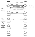
- a message (Msg0) that specifies a signal sequence of a random access preamble or a random access response (Msg2) that is a response to the random access preamble (Msg1) may be used as the control message.
- Msg0 a message that specifies a signal sequence of a random access preamble or a random access response (Msg2) that is a response to the random access preamble (Msg1)
- Msg1 a message that specifies a signal sequence of a random access preamble or a random access response (Msg2) that is a response to the random access preamble
- Msg1 a message that specifies a signal sequence of a random access preamble or a random access response (Msg2) that is a response to the random access preamble (Msg1)
- Msg1 a message that specifies a signal sequence of
- the wireless communication device 2 may continue the subsequent random access procedure in the frequency band # 2 when receiving the control message including the identification information in the frequency band # 1. Further, when the frequency band # 2 is in an inactive state, the wireless communication device 2 may change the frequency band # 2 to an active state when receiving a control message including identification information. Further, the wireless communication device 1 may change the frequency band # 2 to the active state when receiving the control message including the identification information. In this case, the wireless communication devices 1 and 2 do not need to separately transmit and receive a control message for changing the frequency band # 2 to the active state.
- the wireless communication device 1 selects the frequency band # 2 as the frequency band used for data communication by the wireless communication device 2.
- a control message including identification information indicating the frequency band # 2 is transmitted to the wireless communication apparatus 2 in the frequency band # 1.
- the control message including the identification information indicating the frequency band # 2 is received from the wireless communication apparatus 1 in the frequency band # 1 during the random access procedure by the wireless communication apparatus 2. Then, data communication is executed using the frequency band # 2 indicated by the identification information.
- the use permission of the frequency band # 2 different from the frequency band # 1 used at the start of the random access procedure can be given to the wireless communication apparatus 2 during the random access procedure. That is, cross-carrier scheduling can be realized during the random access procedure. Therefore, it is not necessary to separately perform a procedure for giving the wireless communication device 2 permission to use the frequency band # 2 after the random access procedure, and the use control of a plurality of frequency bands can be performed efficiently.
- the radio communication method according to the first embodiment is applied to an LTE-A mobile communication system
- the radio communication method of the first embodiment can also be applied to a mobile communication system using a communication method other than LTE-A and a fixed radio communication system.
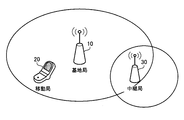
- FIG. 2 is a diagram illustrating the mobile communication system according to the second embodiment.
- the mobile communication system according to the second embodiment includes a base station 10, a mobile station 20, and a relay station 30.
- wireless communication using a maximum of five component carriers is possible.
- the base station 10 is a wireless communication device that communicates with the mobile station 20 directly or via the relay station 30.
- the base station 10 is connected to a host station (not shown) by wire, and transfers user data between a wired section and a wireless section.
- the base station 10 manages the radio resources of the link between the base station 10 and the mobile station 20 and the radio resources of the link between the base station 10 and the relay station 30.
- the mobile station 20 is a wireless terminal device that accesses the base station 10 or the relay station 30 and performs wireless communication.
- a mobile phone or a portable information terminal device can be used.
- the mobile station 20 performs random access to the base station 10 or the relay station 30 to establish synchronization, and then transmits and receives data.
- the relay station 30 is a wireless communication device that relays data transmission between the base station 10 and the mobile station 20.
- the relay station 30 may be a fixed communication device or a mobile communication device.
- the relay station 30 may establish synchronization by performing random access to the base station 10. Further, the relay station 30 manages the radio resources of the link between the relay station 30 and the mobile station 20.
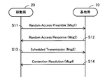
- FIG. 3 is a sequence diagram showing a procedure for contention type random access. The sequence shown in FIG. 3 will be described along with step numbers. Here, it is assumed that a random access procedure is performed by closing to one component carrier.
- Step S11 When data to be transmitted on the uplink (UL) is generated, the mobile station 20 selects one arbitrary signal sequence from a plurality of predefined signal sequences. Then, a random access preamble (Msg1) including the selected signal sequence is transmitted to the base station 10 using a physical random access channel (PRACH: Physical Random Access CHannel). At this time, on the PRACH, a plurality of mobile stations may transmit Msg1 of the same signal sequence, that is, random access may compete.
- PRACH Physical Random Access CHannel
- Step S12 When the base station 10 detects Msg1 on the PRACH, the base station 10 measures the UL transmission timing of the mobile station 20 and allocates UL radio resources to the mobile station 20. And the random access response (Msg2) containing the information for synchronizing UL timing and the information which shows the allocated UL radio
- Step S13 Upon receiving Msg2, the mobile station 20 transmits a scheduled transmission (Msg3) including the identification information of the mobile station 20 to the base station 10 using the UL radio resource allocated by the base station 10.
- Msg3 a scheduled transmission
- each mobile station that has transmitted Msg1 (that is, has received Msg2) transmits Msg3. In this case, a plurality of Msg3 transmitted on the same radio resource interfere.
- Step S14 The base station 10 detects Msg3 on the UL radio resource allocated in step S12.
- the mobile station 20 that has performed random access can be recognized from the identification information included in Msg3.
- the base station 10 transmits to the mobile station 20 contention resolution (Msg4) indicating that the mobile station 20 has been recognized. Thereafter, synchronization is established between the base station 10 and the mobile station 20, and data communication becomes possible.
- Msg4 mobile station 20 contention resolution
- the base station 10 transmits a message indicating that contention has occurred.
- the mobile station 20 that has received the message waits for a random time and then returns to step S11 to re-execute the random access procedure.
- the contention is resolved, synchronization is established between the base station 10 and the mobile station 20, and data communication becomes possible.
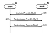
- FIG. 4 is a sequence diagram showing a non-contention type random access procedure. The sequence shown in FIG. 4 will be described along with step numbers. Here, it is assumed that a random access procedure is performed by closing to one component carrier.
- Step S21 When the data to be transmitted on the downlink (DL) arrives, the base station 10 selects one unused signal sequence from a plurality of predefined signal sequences. Then, an individual preamble notification (Msg0) designating the selected signal sequence is transmitted to the mobile station 20. At this time, the base station 10 performs exclusive control so that the same signal sequence is not assigned to a plurality of mobile stations at the same time.
- Msg0 individual preamble notification
- Step S22 The mobile station 20 transmits Msg1 including the signal sequence specified by Msg0 to the base station 10 using the PRACH within a predetermined time (expiration date) after receiving Msg0.
- the designated signal sequence is exclusively allocated to the mobile station 20 within the expiration date, no random access contention occurs.
- Step S23 When the base station 10 detects Msg1 on the PRACH, the base station 10 allocates a UL radio resource to the mobile station 20. Then, Msg 2 including information indicating the allocated UL radio resource is transmitted to the mobile station 20. Thereafter, data communication is possible between the base station 10 and the mobile station 20. Since no contention occurs, Msg3 and Msg4 do not need to be transmitted and received in non-contention type random access.
- the contention-type random access can be executed, for example, when (1) the mobile station 20 first accesses the base station 10 and (2) when the mobile station 20 requests the base station 10 to allocate radio resources.
- Non-contention type random access is, for example, (3) when the mobile station 20 establishes synchronization when receiving data from the base station 10, and (4) the mobile station 20 is handed over from another base station to the base station 10. May be executed when establishing synchronization with the base station 10.
- the signal sequence to be individually assigned is the base station 10 Msg0 that does not include an individual preamble is transmitted / received.
- contention type random access may be performed.
- Msg0 is transmitted to the mobile station 20 by the base station before the handover.
- the base station 10 and the mobile station 20 execute a non-contention type random access procedure.
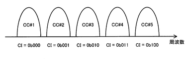
- FIG. 5 is a diagram showing component carriers used for wireless communication. As described above, the base station 10 and the mobile station 20 can perform wireless communication using a maximum of five component carriers (CC # 1 to # 5). The bandwidths of CC # 1 to CC # 5 may all be the same or different.
- Each of CC # 1 to CC # 5 is given a 3-bit CI (Carrier Indicator) as identification information.
- 0b000 (0) indicates CC # 1
- 0b001 (1) indicates CC # 2
- 0b010 (2) indicates CC # 3
- 0b011 (3) indicates CC # 4
- 0b100 (4) indicates CC # 2.
- # 5 is shown.
- 0b101 (5) and 0b110 (6) are unused values (reserved values).
- 0b111 (7) may be used to indicate its own component carrier, as will be described later.
- the base station 10 sets the states of CCs # 1 to # 5 for each mobile station.
- the mobile station 20 controls radio reception processing for each component carrier based on the states of CC # 1 to # 5.
- CCs # 1 to # 5 can be classified into “Configured but Deactivated CC”, “Configured and Activated CC”, and “PDCCH monitoring set” depending on their states.
- “Configured” but “Deactivated” CC is a component carrier that is not currently used for data communication but can be used (inactivated).
- the mobile station 20 uses a downlink physical control channel (PDCCH: Physical-Downlink-Control-CHannel) in which control information is transmitted and a downlink physical shared channel (PDSCH: Physical-Downlink) in which a data signal is transmitted. None of (Shared CHannel) need be monitored. That is, the radio reception process for the frequency band may be stopped.
- Configured and activated CC is a component carrier that is currently used for data communication (active state).
- the mobile station 20 performs a radio reception process on at least the PDSCH addressed to the mobile station 20.
- “PDCCH monitoring” set is a set of component carriers that are in an active state and in which a PDCCH addressed to the mobile station 20 may be set.
- the mobile station 20 monitors the PDCCH on the component carriers included in this set.
- the mobile station 20 performs blind decoding on the PDCCH. That is, the control information is extracted by trying a plurality of types of decoding according to the length of a signal that can be taken.
- “PDCCH monitoring set” can be defined as a subset of “Configured and Activated CC”, but there are cases where PDCCH reception processing should be performed with all “Configured and ⁇ ⁇ Activated CC”. In this case, “PDCCH monitoring set” and “Configured and Activated CC” mean the same set.
- the component carrier to which the PDCCH can be set may be different for each mobile station.
- the base station 10 may set a part of the CCs # 1 to # 5 as an anchor component carrier (ACC).
- the ACC is a component carrier to be monitored by the mobile station.
- “PDCCH monitoring set” includes at least the ACC.
- the component carrier set in ACC may be specified for each cell or for each mobile station.
- the base station 10 and the mobile station 20 may use time division duplex (TDD) or frequency division duplex (FDD) to perform bidirectional communication. May be.
- TDD time division duplex
- FDD frequency division duplex
- TDD time division duplex
- FDD frequency division duplex
- TDD time division duplex
- FDD frequency division duplex
- a pair of a frequency band for UL and a frequency band for DL is set for each CC.
- the random access procedure to be described later can be executed both when the UL frequency band and the DL frequency band are separated from each other.
- FIG. 6 is a block diagram showing the base station.
- the base station 10 includes a wireless communication unit 11, a scheduler 12, a wired communication unit 13, a control unit 14, a control plane unit 15, a PDCCH control unit 16, a data plane unit 17, and a RAR control unit 18.
- the wireless communication unit 11 is a wireless interface that performs wireless communication with the mobile station 20 and the relay station 30.
- the radio communication unit 11 performs signal processing including demodulation and decoding on the radio signal received from the mobile station 20 or the relay station 30, and extracts user data and control information. Also, user data and control information transmitted to the mobile station 20 or the relay station 30 are subjected to signal processing including coding / modulation and wirelessly transmitted.
- the scheduler 12 assigns (schedules) radio resources to the mobile station 20 and the relay station 30 in accordance with instructions from the control unit 14. For example, the scheduler 12 assigns a UL radio resource to the mobile station 20 during a random access procedure, and notifies the radio communication unit 11 of the assigned UL radio resource.
- the wired communication unit 13 is a communication interface that performs wired communication with an upper station.
- the wired communication unit 13 receives user data addressed to the mobile station 20 from the upper station.
- the received user data is transferred to the mobile station 20 under scheduling by the scheduler 12. Further, the wired communication unit 13 transfers the user data extracted by the wireless communication unit 11 to the upper station.
- the control unit 14 controls processing of the wireless communication unit 11, the scheduler 12, and the wired communication unit 13.
- a control plane unit 15 and a data plane unit 17 are provided in the control unit 14.
- a PDCCH control unit 16 is provided in the control plane unit 15.
- a RAR control unit 18 is provided in the data plane unit 17.
- the control plane unit 15 controls transmission / reception of control information between the mobile station 20 and the relay station 30. That is, the control information extracted by the wireless communication unit 11 is acquired, and communication control according to the control information is performed. In addition, the wireless communication unit 11 is notified of control information to be transmitted to the mobile station 20 or the relay station 30. For example, the control plane unit 15 performs processing of RRC (Radio Resource Control Control Protocol).
- RRC Radio Resource Control Control Protocol
- the PDCCH control unit 16 controls PDCCH signaling during a random access procedure. That is, what information is included in the dedicated preamble notification (Msg0) transmitted on the PDCCH to the mobile station 20 or the relay station 30 is determined. For example, the CI of the component carrier used for data communication may be inserted into Msg0.
- Msg0 dedicated preamble notification
- the data plane unit 17 controls transmission / reception of user data between the mobile station 20 and the relay station 30.
- the data plane unit 17 performs PDCP (Packet Data Convergence Protocol), RLC (Radio Link Control) protocol, and MAC (Media Access Control) protocol processing.
- PDCP Packet Data Convergence Protocol
- RLC Radio Link Control
- MAC Media Access Control
- the RAR control unit 18 controls the MAC signaling during the random access procedure. That is, what information is included in the random access response (Msg2) transmitted to the mobile station 20 or the relay station 30 by PDSCH is determined. For example, the CI of the component carrier used for data communication may be inserted into Msg2.
- FIG. 7 is a block diagram showing a mobile station.
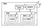
- the mobile station 20 includes a radio communication unit 21, a cross carrier setting unit 22, a control unit 23, a control plane unit 24, a PDCCH control unit 25, a data plane unit 26, and a RAR control unit 27.
- the wireless communication unit 21 is a wireless interface that performs wireless communication with the base station 10 and the relay station 30.
- the radio communication unit 21 performs signal processing including demodulation and decoding on the radio signal received from the base station 10 or the relay station 30, and extracts user data and control information.
- signal processing including coding / modulation is performed on user data and control information transmitted to the base station 10 or the relay station 30 and wirelessly transmitted.
- the cross carrier setting unit 22 sets a frequency band (component carrier) in which the radio communication unit 21 performs signal processing during a random access procedure. For example, when the received Msg0 or Msg2 includes a CI, settings are made so that data communication can be performed using the component carrier indicated by the CI thereafter. In the second embodiment, it is assumed that a CI is inserted in Msg0.
- the control unit 23 controls processing of the wireless communication unit 21 and the cross carrier setting unit 22.
- a control plane unit 24 and a data plane unit 26 are provided in the control unit 23.
- a PDCCH control unit 25 is provided in the control plane unit 24.
- a RAR control unit 27 is provided in the data plane unit 26.
- the control plane unit 24 controls transmission / reception of control information between the base station 10 and the relay station 30. That is, the control information extracted by the wireless communication unit 21 is acquired, and communication control according to the control information is performed. In addition, the wireless communication unit 21 is notified of control information to be transmitted to the base station 10 or the relay station 30. For example, the control plane unit 24 performs RRC processing.
- the PDCCH control unit 25 controls PDCCH signaling during a random access procedure. That is, Msg0 received on the PDCCH from the base station 10 or the relay station 30 is analyzed, and processing based on information included in Msg0 is performed. For example, when a CI is inserted in Msg0, a PDSCH reception process can be performed on the component carrier indicated by the CI.
- the start of reception processing may include activation of a component carrier, allocation of a buffer for storing received user data, and the like.
- the data plane unit 26 controls transmission / reception of user data between the base station 10 and the relay station 30. For example, PDCH, RLC, and MAC are processed.
- the RAR control unit 27 controls MAC signaling during a random access procedure. That is, Msg2 received on the PDSCH from the base station 10 or the relay station 30 is analyzed, and processing based on information included in Msg2 is performed. For example, when a CI is inserted in Msg2, a PDSCH reception process can be performed on a component carrier indicated by the CI.
- the relay station 30 can also be provided with a wireless communication unit and a control unit.
- the control unit of the relay station 30 performs the same processing as the control unit 23 of the mobile station 20 with respect to wireless communication with the base station 10.
- the same processing as the control unit 14 of the base station 10 is performed.
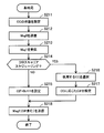
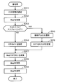
- FIG. 8 is a flowchart illustrating base station processing according to the second embodiment. The process illustrated in FIG. 8 will be described along with step numbers.
- Step S111 The control unit 14 sets the states of CCs # 1 to # 5 for the mobile station 20. That is, the above-mentioned “Configured but Deactivated CC”, “Configured and Activated CC”, and “PDCCH monitoring set” are specified.
- Step S112 The control unit 14 determines whether or not to perform cross-carrier scheduling. That is, it is determined whether data communication is performed using a component carrier other than the component carrier that transmits the dedicated preamble notification (Msg0). Whether to perform cross-carrier scheduling is determined based on, for example, the size of data transmitted to the mobile station 20, the communication quality of the component carrier that transmits Msg0, and the like.
- cross carrier scheduling is not performed, the process proceeds to step S113. If so, the process proceeds to step S114.
- Step S113 The PDCCH control unit 16 sets 0b111 in the CI field (CIF) included in Msg0. This bit string indicates that data communication is performed using a component carrier to which Msg0 is transmitted. Instead of 0b111, a 3-bit CI indicating a component carrier to which Msg0 is transmitted may be set. Then, the process proceeds to step S116.
- CIF CI field
- Step S114 The control unit 14 selects one or a plurality of component carriers to be used for data communication from CC # 1 to CC # 5 other than the component carrier to which Msg0 is transmitted.
- the component carrier is selected based on, for example, the size of data to be transmitted to the mobile station 20, the communication quality of CCs # 1 to # 5, and the like.
- Step S115 The PDCCH control unit 16 sets a 3-bit CIF indicating the component carrier selected in Step S114 in the CIF included in Msg0. Msg0 is transmitted for each component carrier selected in step S114.
- Step S116 The wireless communication unit 11 transmits Msg0 including the CIF set in step S113 or step S115 to the mobile station 20 using the component carrier included in “PDCCH monitoring” set.
- a plurality of component carriers are selected in step S114, a plurality of Msg0s are transmitted.
- the plurality of Msg0s may be transmitted in the same radio transmission unit (for example, the same subframe) or may be transmitted in a distributed manner in different radio transmission units (for example, different subframes).
- Step S117 When the component carrier notified by Msg0 is “Configured but Deactivated CC” (inactive state), the control unit 14 changes to “Configured and Activated CC” (active state).
- the wireless communication unit 11 receives the random access preamble (Msg1) from the mobile station 20 using the component carrier notified by Msg0.
- Step S118 The RAR control unit 18 generates a random access response (Msg2) that does not include the CIF.
- the wireless communication unit 11 transmits Msg2 to the mobile station 20 using the component carrier from which Msg1 has been received. Thereafter, data communication is performed with the component carrier used for transmission and reception of Msg1 and Msg2.
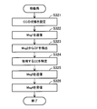
- FIG. 9 is a flowchart illustrating mobile station processing according to the second embodiment. The process illustrated in FIG. 9 will be described along with step numbers.
- the control unit 23 sets the states of CCs # 1 to # 5. That is, “Configured but Deactivated CC”, “Configured and Activated CC”, and “PDCCH monitoring set” are specified.
- the radio communication unit 21 monitors the PDCCH of the component carrier included in the “PDCCH monitoring set”.
- Step S122 The wireless communication unit 21 receives Msg0 from the base station 10 using a component carrier included in “PDCCH monitoring” set.
- the PDCCH control unit 25 extracts the CIF included in Msg0. When a plurality of Msg0s are received, the CIF is extracted for each Msg0.
- Step S123 The PDCCH control unit 25 identifies the component carrier indicated by the CIF extracted in Step S122, and sets the component carrier in a state where PDSCH reception processing can be performed.
- the component carrier indicated by the CIF is “Configured but Deactivated CC”, it is changed to “Configured and Activated CC”.
- the cross carrier setting unit 22 sets a frequency band for performing signal processing.
- Step S124 The wireless communication unit 21 transmits Msg1 using the signal sequence specified by Msg0 to the base station 10 using the PRACH of the component carrier indicated by the CIF.
- Msg1 is transmitted for each identified component carrier.
- the plurality of Msg1s may be transmitted at the same timing or at different timings.
- Step S125 The wireless communication unit 21 receives Msg2 from the base station 10 using the component carrier used for transmission of Msg1.
- the RAR control unit 27 performs processing based on information included in Msg2. Thereafter, data communication is performed with the component carrier used for transmission and reception of Msg1 and Msg2.
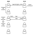
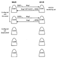
- FIG. 10 is a diagram illustrating a first random access example according to the second embodiment.
- CC # 1 and # 2 are set to “Configured and Activated CC” and CC # 3 to # 5 are set to “Configured but Deactivated CC”.
- PDCH monitoring set includes only CC # 1.
- Step S133 The base station 10 transmits Msg2 to the mobile station 20 using CC # 2 that has received Msg1. Thereafter, in CC # 2, for example, the mobile station 20 transmits data to the base station 10.
- CC # 1 is set to “PDCCHDCmonitoring set” for the sake of simplicity of explanation, but any CC can be “PDCCH monitoring set”.
- Msg0 can be transmitted from the CC set in “PDCCH monitoring set”.
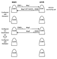
- FIG. 11 is a diagram illustrating a second random access example according to the second embodiment.
- the states of CCs # 1 to # 5 at the start of the random access procedure are the same as in FIG. (Step S141)
- Step S143 The base station 10 transmits Msg2 to the mobile station 20 using CC # 3 that has received Msg1. Thereafter, in CC # 3, for example, the mobile station 20 transmits data to the base station 10.
- the base station 10 and the mobile station 20 are changing the state of CC # 3 during the procedure of transmitting and receiving Msg0 and Msg1. That is, Msg0 and Msg1 also serve as signaling for changing the state of CC # 3. Therefore, the base station 10 and the mobile station 20 do not need to separately perform signaling for changing the state of CC # 3.
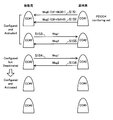
- FIG. 12 is a diagram illustrating a third random access example according to the second embodiment.
- the states of CCs # 1 to # 5 at the start of the random access procedure are the same as in FIG. (Step S151)
- Step S155 The base station 10 receives Msg1 and transmits Msg2 to the mobile station 20 in CC # 2. Thereafter, in CC # 2, for example, the mobile station 20 transmits data to the base station 10.
- Step S156 The base station 10 receives Msg1 and transmits Msg2 to the mobile station 20 in CC # 3. Thereafter, in CC # 3, for example, the mobile station 20 transmits data to the base station 10.
- the signal sequence specified by Msg0 transmitted in step S151 and the signal sequence specified by Msg0 transmitted in step S152 may be the same or different. That is, Msg1 transmitted by the mobile station 20 in step S153 and Msg1 transmitted in step S154 may be the same signal sequence or different signal sequences.
- cross carrier scheduling described above assumes that the base station 10 recognizes the states of CCs # 1 to # 5 of the mobile station 20. When there is a situation in which some of the component carriers out of CC # 1 to # 5 cannot be used by the base station 10 or the mobile station 20, the base station 10 excludes such component carriers and uses them for data communication. Select.
- the cross carrier scheduling described above can be executed when the mobile station 20 performs random access to the base station 10 from the connected mode or the idle mode, for example.
- FIG. 13 is a diagram illustrating a first format example of Msg0.
- Msg0 is a control message transmitted on the PDCCH.
- Msg0 includes Flag, Local / Dist, Resource Block Assignment, Preamble Index, PRACH Mask Index, Carrier Indicator, and CRC as fields.
- the bit length of the Resource Block Assignment field differs depending on the DL bandwidth of the component carrier. In FIG. 13, the bandwidth is represented by the number of resource blocks (RB). 100RB corresponds to a 20 MHz width.
- E-UTRA Evolved Universal Terrestrial Radio Access
- Flag is fixed to 1
- Local / Dist is fixed to 0
- Resource Block Assignment is all fixed to 1.
- Preamble Index is information specifying a signal sequence used for Msg1.
- Index is information used for transmission of Msg1.
- CRC is a parity used for error detection of Msg0.
- CarrieratorIndicator is a 3-bit bit string for designating a component carrier used for data transmission.
- a CarrierCarIndicator field is inserted between the PRACH Mask Index field and the CRC field.
- E-UTRA Evolved Universal Terrestrial Radio Access
- Multiplexing channel and channel coding describes a format in which a Padding field is provided between a PRACH Mask Index field and a CRC field.
- FIG. 14 is a diagram illustrating a second format example of Msg0.
- the first 3 bits of the bit string assigned to the Resource Block ⁇ ⁇ ⁇ ⁇ ⁇ Assignment field in the format example of FIG. 13 are assigned to the Carrier Indicator field. That is, a Carrier Indicator field is inserted between the Local / Dist field and the Resource Block Assignment field.
- a Padding field is provided between the PRACH Mask Index field and the CRC field. Padding is fixed to all 1.
- FIG. 15 is a diagram illustrating a third format example of Msg0.
- the last 3 bits of the bit string assigned to the Resource ⁇ Block ⁇ ⁇ ⁇ ⁇ ⁇ Assignment field in the format example of FIG. 13 are assigned to the Carrier Indicator field. That is, the Carrier Indicator field is inserted between the Resource Block Assignment field and the Preamble Index.
- the data length of Msg0 differs depending on the DL bandwidth of the component carrier. For this reason, a plurality of Msg0s having different data lengths may be transmitted using CC # 1. For example, it is assumed that the DL bandwidth of CC # 2 is 20 MHz and the DL bandwidth of CC # 3 is 10 MHz. In this case, Msg0 corresponding to CC # 2 and Msg0 corresponding to CC # 3 have different data lengths.
- the mobile station 20 performs blind decoding on the PDCCH to extract Msg0. Therefore, in order to reduce the load of blind decoding, it is preferable to perform size adjustment so that the size of Msg0 is constant even if the DL bandwidth varies depending on the component carrier. Furthermore, in order to facilitate the extraction of CIF, it is preferable that the position of CIF in the entire Msg0 is constant.
- FIG. 16 is a diagram illustrating a first size adjustment example of Msg0.
- the size adjustment example in FIG. 16 corresponds to the format example shown in FIG.
- PADDING having a length corresponding to the DL bandwidth is inserted between the Resource Block Assignment field and the Preamble Index field. This makes the size of Msg0 constant regardless of the DL bandwidth.
- the position of the CIF is constant, it becomes easy to extract the CIF and specify the component carrier to be used after decoding Msg0.
- the positions of the Preamble Index field and the PRACH Mask Index field are also constant, it is easy to generate Msg1 with reference to these fields.
- FIG. 17 is a diagram illustrating a second size adjustment example of Msg0.
- the size adjustment example in FIG. 17 corresponds to the format example shown in FIG.
- PADDING having a length corresponding to the DL bandwidth is inserted between the Resource Block Assignment field and the Preamble Index field. This makes the size of Msg0 constant and the CIF position constant regardless of the DL bandwidth.
- the positions of the Preamble Index field and the PRACH Mask Index field are also constant.
- FIG. 18 is a diagram illustrating a third size adjustment example of Msg0.
- the size adjustment example in FIG. 18 corresponds to the format example shown in FIG.
- PADDING having a length corresponding to the DL bandwidth is inserted between the Local / Dist field and the Resource Block Assignment field. This makes the size of Msg0 constant and the CIF position constant regardless of the DL bandwidth.
- the positions of the Preamble Index field and the PRACH Mask Index field are also constant.
- the base station 10 gives the mobile station 20 permission to use component carriers other than the component carrier that has transmitted Msg0 by transmitting Msg0. Can do. That is, cross carrier scheduling can be realized using Msg0. Therefore, the base station 10 and the mobile station 20 do not need to separately perform a procedure for permitting use of the component carrier.
- the base station 10 and the mobile station 20 change the inactive component carrier to the active state in accordance with transmission / reception of Msg0 and Msg1. Therefore, it is not necessary to separately perform a procedure for changing the state of the component carrier.
- the base station 10 and the mobile station 20 can efficiently execute use control of a plurality of component carriers.
- the mobile communication system of the third embodiment can be realized by the same system configuration as the mobile communication system of the second embodiment shown in FIG.
- the base station and mobile station of the third embodiment can be realized by the same block configuration as the base station 10 and mobile station 20 of the second embodiment shown in FIGS.
- the third embodiment will be described using the reference numerals used in FIGS.
- FIG. 19 is a flowchart illustrating base station processing according to the third embodiment. The processing illustrated in FIG. 19 will be described along with step numbers.
- the control unit 14 sets the states of CCs # 1 to # 5 for the mobile station 20. That is, the above-mentioned “Configured but Deactivated CC”, “Configured and Activated CC”, and “PDCCH monitoring set” are specified.
- Step S212 The PDCCH control unit 16 generates an individual preamble notification (Msg0) that does not include the CIF.
- the wireless communication unit 11 transmits Msg0 to the mobile station 20 using the component carrier included in “PDCCH monitoring set”.
- Step S213 The wireless communication unit 11 receives the random access preamble (Msg1) from the mobile station 20 using the component carrier used for transmission of Msg0.
- Step S214 The control unit 14 determines whether to perform cross carrier scheduling. That is, it is determined whether to perform data communication other than the component carrier that transmits the random access response (Msg2). When cross carrier scheduling is not performed, the process proceeds to step S215. If so, the process proceeds to step S216.
- Step S215) The RAR control unit 18 sets 0b111 to the CIF included in Msg2. This bit string indicates that data communication is performed using a component carrier to which Msg2 is transmitted. Then, the process proceeds to step S218.
- Step S216 The control unit 14 selects one or a plurality of component carriers to be used for data communication from CC # 1 to # 5, in addition to the component carrier to which Msg2 is transmitted.
- Step S21-7 The RAR control unit 18 sets a 3-bit CIF indicating the component carrier selected in step S216. Msg2 is transmitted for each component carrier selected in step S216.
- Step S228 The wireless communication unit 11 transmits Msg2 including the CIF set in Step S215 or Step S217 to the mobile station 20 using the component carrier included in “PDCCH monitoring” set.
- a plurality of component carriers are selected in step S216, a plurality of Msg2 are transmitted.
- the control unit 14 changes it to “Configured and Activated CC” (active state). Thereafter, data communication is performed using the component carrier notified by Msg2.
- FIG. 20 is a flowchart illustrating mobile station processing according to the third embodiment. The process illustrated in FIG. 20 will be described along with step numbers.
- the control unit 23 sets the states of CCs # 1 to # 5. That is, “Configured but Deactivated CC”, “Configured and Activated CC”, and “PDCCH monitoring set” are specified.
- the radio communication unit 21 monitors the PDCCH of the component carrier included in the “PDCCH monitoring set”.
- Step S ⁇ b> 222 The wireless communication unit 21 receives Msg ⁇ b> 0 that does not include CIF from the base station 10 using the component carrier included in the “PDCCH monitoring set”. (Step S223) The radio communication unit 21 transmits Msg1 using the signal sequence specified by Msg0 to the base station 10 using the PRACH of the component carrier used for transmission of Msg0.
- Step S224 The wireless communication unit 21 receives Msg2 from the base station 10 on the component carrier used for transmission of Msg1.
- the RAR control unit 27 extracts the CIF included in Msg2. When a plurality of Msg2s are received, the CIF is extracted for each Msg2.
- Step S225 The RAR control unit 27 specifies one or a plurality of component carriers indicated by the CIF extracted in step S224, and sets a state in which PDSCH reception processing can be performed using the component carriers.
- the component carrier indicated by the CIF is “Configured but Deactivated CC”, it is changed to “Configured and Activated CC”.
- the cross carrier setting unit 22 sets a frequency band for performing signal processing.
- Step S226) The wireless communication unit 21 performs data communication using the component carrier specified in Step S225.
- FIG. 21 is a diagram illustrating a first random access example according to the third embodiment.
- CC # 1 and # 2 are set to “Configured and Activated CC”
- CC # 3 to # 5 are set to “Configured but Deactivated CC”.
- PDCH monitoring set includes only CC # 1.
- Step S ⁇ b> 231 The base station 10 transmits Msg ⁇ b> 0 to the mobile station 20 using CC # 1 that is “PDCCH monitoring set”.
- Step S232 The mobile station 20 transmits Msg1 to the base station 10 using CC # 1 that has received Msg0.
- FIG. 22 is a diagram illustrating a second random access example according to the third embodiment.
- the states of CCs # 1 to # 5 at the start of the random access procedure are the same as in FIG. (Step S241)
- the base station 10 transmits Msg0 to the mobile station 20 using CC # 1 that is “PDCCH monitoring set”.
- Step S242 The mobile station 20 transmits Msg1 to the base station 10 using CC # 1 that has received Msg0.
- FIG. 23 is a diagram illustrating a third random access example according to the third embodiment.
- the states of CCs # 1 to # 5 at the start of the random access procedure are the same as in FIG. (Step S ⁇ b> 251)
- the base station 10 transmits Msg ⁇ b> 0 to the mobile station 20 using CC # 1 that is “PDCCH monitoring set”.
- Step S252 The mobile station 20 transmits Msg1 to the base station 10 using CC # 1 that has received Msg0.
- the Msg2 includes timing adjustment information for the UL frequency band of CC # 2.
- the Msg2 includes timing adjustment information for the UL frequency band of CC # 3.
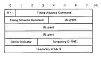
- FIG. 24 is a diagram illustrating a first format example of Msg2.
- Msg2 includes 3-bit Carrier-Indicator, 6-bit Timing-Advance-Command, 20-bit UL-grant, and 16-bit Temporary-C-RNTI.
- Carrier ⁇ Indicator is a value for identifying a component carrier used for data transmission.
- Timing Advance Command is a value indicating a correction amount when the mobile station 20 corrects the UL transmission timing.
- UL grant is information indicating the UL radio resource allocated to the mobile station 20.
- Temporary C-RNTI is an identifier dynamically allocated to the mobile station 20 by the base station 10. Note that “Timing Advance Command” indicates a correction amount for the component carrier indicated by the CarrieratorIndicator. Therefore, the mobile station 20 adjusts the UL transmission timing after the random access procedure using TimingTiAdvance Command.
- Timing Advance Command is described in, for example, “Evolved Universal Terrestrial Radio Access (E-UTRA); Physical Layer Procedures” (3GPP TS 36.213 V9.0.1, 2009-11).
- timing Advance Command two types: absolute value of timing deviation and relative value based on the current corrected timing.
- the absolute value is used when a Timing Advance Command is notified for the first time, or when a previously notified Timing Advance Command has expired.
- the relative value is used when the expiration date of the previously notified Timing Advance Command has not expired.
- the absolute value is represented by 11 bits and the relative value is represented by 6 bits.
- the format example in FIG. 24 assumes that relative values are used.
- the reserved bit at the beginning is set to 1.
- the leading R bit of Msg2 not including CIF is set to zero. Thereby, the mobile station 20 can easily determine whether or not it is Msg2 including CIF.
- FIG. 25 is a diagram illustrating a second format example of Msg2.
- Msg2 includes 11-bit Timing / Advance / Command, 20-bit UL / grant, 3-bit Carrier / Indicator, and 13-bit Temporary / C-RNTI.
- an absolute value can be used as Timing ⁇ ⁇ ⁇ Advance Command.
- Temporary C-RNTI is 3 bits less than in the case of FIG.
- the base station 10 assigns an identifier that can be expressed by 13 bits or less to the mobile station 20.
- FIG. 26 is a diagram illustrating a third format example of Msg2.
- Msg2 includes 11-bit Timing / Advance / Command, 20-bit UL / grant, 16-bit Temporary / C-RNTI, and 3-bit Carrier / Indicator.
- an absolute value can be used as Timing ⁇ ⁇ ⁇ Advance Command.
- the base station 10 can assign a value identifier to the mobile station 20 as compared with the case of FIG.
- the size of Msg2 is larger than the format examples of FIGS.
- the CIF is provided at the end, but the CIF may be inserted at another position.
- the base station 10 gives the mobile station 20 permission to use component carriers other than the component carrier that has transmitted Msg2 by transmitting Msg2. Can do. That is, cross carrier scheduling can be realized using Msg2. Therefore, the base station 10 and the mobile station 20 do not need to separately perform a procedure for permitting use of the component carrier.
- the base station 10 and the mobile station 20 change the inactive component carrier to the active state in accordance with transmission / reception of Msg2. Therefore, it is not necessary to separately perform a procedure for changing the state of the component carrier.
- the base station 10 and the mobile station 20 can efficiently execute use control of a plurality of component carriers, as in the second embodiment.
- the mobile communication system of the fourth embodiment can be realized by the same system configuration as the mobile communication system of the second embodiment shown in FIG.
- the base station and mobile station of the fourth embodiment can be realized by the same block configuration as the base station 10 and mobile station 20 of the second embodiment shown in FIGS.
- the fourth embodiment will be described using the reference numerals used in FIGS.
- FIG. 27 is a flowchart illustrating base station processing according to the fourth embodiment. The processing illustrated in FIG. 27 will be described along with step numbers.
- Step S311 The control unit 14 sets the states of CCs # 1 to # 5 for the mobile station 20. That is, the above-mentioned “Configured but Deactivated CC”, “Configured and Activated CC”, and “PDCCH monitoring set” are specified.
- the wireless communication unit 11 receives the random access preamble (Msg1) from the mobile station 20 by the component carrier included in “PDCCH monitoring” set.
- the signal series used for Msg1 is one that the mobile station 20 randomly selects.
- Step S313 The control unit 14 determines whether to perform cross-carrier scheduling. When cross carrier scheduling is not performed, the process proceeds to step S314. If so, the process proceeds to step S315.
- Step S314 The RAR control unit 18 sets 0b111 to the CIF included in Msg2. Then, the process proceeds to step S317.
- Step S315) The control unit 14 selects one or a plurality of component carriers to be used for data communication from CC # 1 to CC # 5 other than the component carrier to which Msg2 is transmitted.
- Step S316 The RAR control unit 18 sets a 3-bit CIF indicating the component carrier selected in step S315. Msg2 is transmitted for each component carrier selected in step S315.
- Step S317) The wireless communication unit 11 transmits Msg2 including the CIF set in Step S314 or Step S316 on the component carrier that has received Msg1.
- Msg2 including the CIF set in Step S314 or Step S316 on the component carrier that has received Msg1.
- Step S318) The wireless communication unit 11 receives Msg3 from the mobile station 20 by the component carrier notified by Msg2. At this time, when the component carrier notified by Msg2 is “Configured but Deactivated CC” (inactive state), the control unit 14 changes it to “Configured and Activated CC” (active state).
- Step S319) The wireless communication unit 11 transmits Msg4 to the mobile station 20 on the component carrier from which Msg3 has been received. Thereafter, data communication is performed with the component carrier used for transmission and reception of Msg3 and Msg4.
- FIG. 28 is a flowchart illustrating mobile station processing according to the fourth embodiment. The process illustrated in FIG. 28 will be described along with step numbers.
- the control unit 23 sets the states of CCs # 1 to # 5. That is, “Configured but Deactivated CC”, “Configured and Activated CC”, and “PDCCH monitoring set” are specified.
- the radio communication unit 21 monitors the PDCCH of the component carrier included in the “PDCCH monitoring set”.
- Step S322 The wireless communication unit 21 transmits Msg1 using the randomly selected signal sequence to the base station 10 by using the PRACH of the component carrier included in “PDCCH monitoring” set.
- Step S323 The wireless communication unit 21 receives Msg2 from the base station 10 using the component carrier used for transmission of Msg1.
- the RAR control unit 27 extracts the CIF included in Msg2. When a plurality of Msg2s are received, the CIF is extracted for each Msg2.
- Step S324 The RAR control unit 27 specifies one or a plurality of component carriers indicated by the CIF extracted in step S323.
- the component carrier indicated by the CIF is “Configured but Deactivated CC”, it is changed to “Configured and Activated CC”.
- the cross carrier setting unit 22 sets a frequency band for performing signal processing.
- Step S325) The wireless communication unit 21 transmits Msg3 to the base station 10 using the component carrier indicated by the CIF.
- Msg3 is transmitted for each specified component carrier.
- the plurality of Msg3s may be transmitted at the same timing or at different timings.
- Step S326 The wireless communication unit 21 receives Msg4 from the base station 10 using the component carrier used for transmission of Msg3. Thereafter, data communication is performed with the component carrier used for transmission and reception of Msg3 and Msg4.
- FIG. 29 is a diagram illustrating a first random access example according to the fourth embodiment.
- CC # 1 and # 2 are set to “Configured and Activated CC” and CC # 3 to # 5 are set to “Configured but Deactivated CC”.
- PDCH monitoring set includes only CC # 1.
- Step S ⁇ b> 331) The mobile station 20 transmits Msg ⁇ b> 1 using a randomly selected signal sequence to the base station 10 using CC # 1 which is “PDCCH monitoring set”.
- Step S334 The base station 10 transmits Msg4 to the mobile station 20 using CC # 2 that has received Msg3. Thereafter, in CC # 2, for example, the mobile station 20 transmits data to the base station 10. However, if a random access conflict has occurred, the mobile station 20 starts over from the transmission of Msg1.
- FIG. 30 is a diagram illustrating a second random access example according to the fourth embodiment.
- the states of CCs # 1 to # 5 at the start of the random access procedure are the same as in FIG. (Step S341)
- the mobile station 20 transmits Msg1 using a randomly selected signal sequence to the base station 10 using CC # 1 which is “PDCCH monitoring set”.
- the mobile station 20 activates CC # 3 in the same way as the base station 10 and changes it to “Configured and Activated CC”.
- Step S344 The base station 10 transmits Msg4 to the mobile station 20 using CC # 3 that has received Msg3. Thereafter, in CC # 3, for example, the mobile station 20 transmits data to the base station 10.
- FIG. 31 is a diagram illustrating a third random access example according to the fourth embodiment.
- the states of CCs # 1 to # 5 at the start of the random access procedure are the same as in FIG. (Step S ⁇ b> 351)
- the mobile station 20 transmits Msg ⁇ b> 1 using a randomly selected signal sequence to the base station 10 using CC # 1 which is “PDCCH monitoring set”.
- Step S356 The base station 10 transmits Msg4 to the mobile station 20 using CC # 2 that has received Msg3.
- Step S357 The base station 10 transmits Msg4 to the mobile station 20 using CC # 3 that has received Msg3.
- the format example described in the third embodiment can be used as the format of Msg2 in the fourth embodiment.
- the base station 10 may not recognize the mobile station 20 at the time of transmission of Msg2, and therefore, a format such as FIGS. 25 and 26 that can transmit an absolute value TimingTiAdvance Command is used. It is preferable.
- the mobile station 20 can use all or a predetermined plurality of component carriers.
- load distribution is performed so that a plurality of mobile stations do not use specific component carriers in a concentrated manner, and component carriers used for random access procedures are distributed in order to suppress inter-cell interference. It is also conceivable to perform cross-carrier scheduling for the purpose of distributing component carriers used for transmission of Msg3 in order to reduce the competition probability.
- the base station 10 can implement cross carrier scheduling using Msg2 as in the third embodiment. Therefore, it is not necessary to separately perform the procedure for permitting use of the component carrier. Further, the base station 10 and the mobile station 20 change the inactive component carrier to the active state in accordance with transmission / reception of Msg2 and Msg3. Therefore, it is not necessary to separately perform a procedure for changing the state of the component carrier. As described above, the base station 10 and the mobile station 20 can efficiently execute use control of a plurality of component carriers, as in the second and third embodiments.
Landscapes
- Engineering & Computer Science (AREA)
- Computer Networks & Wireless Communication (AREA)
- Signal Processing (AREA)
- Mobile Radio Communication Systems (AREA)
Abstract
Description
本発明の上記および他の目的、特徴および利点は本発明の例として好ましい実施の形態を表す添付の図面と関連した以下の説明により明らかになるであろう。
[第1の実施の形態]
図1は、第1の実施の形態の無線通信システムを示す図である。第1の実施の形態に係る無線通信システムは、無線通信装置1,2を含む。無線通信装置1,2は、複数の周波数帯域を用いて通信を行う。このような無線通信システムは、例えば、LTE-Aシステムとして実現できる。LTE-Aでは、複数の周波数帯域それぞれを、コンポーネントキャリア(CC:Component Carrier)と呼ぶことがある。
図2は、第2の実施の形態の移動通信システムを示す図である。第2の実施の形態に係る移動通信システムは、基地局10、移動局20および中継局30を含む。この移動通信システムでは、最大で5つのコンポーネントキャリアを用いた無線通信が可能である。
RAR制御部27は、ランダムアクセスの手続き時のMACシグナリングを制御する。すなわち、基地局10または中継局30からPDSCHで受信するMsg2を解析し、Msg2に含まれる情報に基づく処理を行う。例えば、Msg2にCIが挿入されている場合、CIが示すコンポーネントキャリアでPDSCHの受信処理を行える状態にする。
(ステップS111) 制御部14は、移動局20についてのCC#1~#5の状態を設定する。すなわち、前述の“Configured but Deactivated CC”、“Configured and Activated CC”および“PDCCH monitoring set”を特定する。
(ステップS121) 制御部23は、CC#1~#5の状態を設定する。すなわち、“Configured but Deactivated CC”、“Configured and Activated CC”および“PDCCH monitoring set”を特定する。無線通信部21は、“PDCCH monitoring set”に含まれるコンポーネントキャリアのPDCCHをモニタリングする。
(ステップS132) 移動局20は、CIF=0b001が示すCC#2でMsg1を基地局10に送信する。CC#2は“Configured and Activated CC”であるため、CC#2の状態変更を行わなくてよい。
(ステップS141) 基地局10は、“PDCCH monitoring set”であるCC#1で、CIF=0b010を含むMsg0を移動局20に送信する。CIF=0b010が示すCC#3は“Configured but Deactivated CC”であるため、CC#3を活性化させて“Configured and Activated CC”に変更しておく。
(ステップS151) 基地局10は、“PDCCH monitoring set”であるCC#1で、CIF=0b001を含むMsg0を移動局20に送信する。
(ステップS154) 移動局20は、CIF=0b010が示すCC#3でMsg1を基地局10に送信する。このとき、移動局20は、基地局10と同様にCC#3を活性化させて“Configured and Activated CC”に変更する。なお、2つのMsg1は同一タイミングで送信してもよい。
次に、第3の実施の形態について説明する。前述の第2の実施の形態との差異を中心に説明し、同様の事項については説明を省略する。第2の実施の形態では、Msg0を用いてクロスキャリアスケジューリングを実現したのに対し、第3の実施の形態では、Msg2を用いてクロスキャリアスケジューリングを実現する。
(ステップS211) 制御部14は、移動局20についてのCC#1~#5の状態を設定する。すなわち、前述の“Configured but Deactivated CC”、“Configured and Activated CC”および“PDCCH monitoring set”を特定する。
(ステップS214) 制御部14は、クロスキャリアスケジューリングを行うか判断する。すなわち、ランダムアクセスレスポンス(Msg2)を送信するコンポーネントキャリア以外でデータ通信を行うか判断する。クロスキャリアスケジューリングを行わない場合、処理をステップS215に進める。行う場合、処理をステップS216に進める。
(ステップS221) 制御部23は、CC#1~#5の状態を設定する。すなわち、“Configured but Deactivated CC”、“Configured and Activated CC”および“PDCCH monitoring set”を特定する。無線通信部21は、“PDCCH monitoring set”に含まれるコンポーネントキャリアのPDCCHをモニタリングする。
(ステップS223) 無線通信部21は、Msg0で指定されている信号系列を用いたMsg1を、Msg0の送信に用いられたコンポーネントキャリアのPRACHで基地局10に送信する。
図21は、第3の実施の形態の第1のランダムアクセス例を示す図である。ここでは、移動局20にとって、CC#1,#2が“Configured and Activated CC”に設定され、CC#3~#5が“Configured but Deactivated CC”に設定されているとする。また、“PDCCH monitoring set”はCC#1のみを含んでいるとする。
(ステップS232) 移動局20は、Msg0を受信したCC#1で、Msg1を基地局10に送信する。
(ステップS241) 基地局10は、“PDCCH monitoring set”であるCC#1で、Msg0を移動局20に送信する。
(ステップS243) 基地局10は、Msg1を受信したCC#1で、CIF=0b010を含むMsg2を移動局20に送信する。CIF=0b010が示すCC#3は、“Configured but Deactivated CC”であるため、CC#3を活性化させて“Configured and Activated CC”に変更しておく。なお、Msg2には、CC#3のUL周波数帯域についてのタイミング調整情報が含まれている。
(ステップS251) 基地局10は、“PDCCH monitoring set”であるCC#1で、Msg0を移動局20に送信する。
(ステップS253) 基地局10は、Msg1を受信したCC#1で、CIF=0b001を含むMsg2を移動局20に送信する。なお、このMsg2には、CC#2のUL周波数帯域についてのタイミング調整情報が含まれている。
(ステップS256) 移動局20は、CIF=0b010が示すCC#3において、例えば、基地局10にデータを送信する。このとき、移動局20は、基地局10と同様にCC#3を活性化させて“Configured and Activated CC”に変更する。
次に、第4の実施の形態について説明する。前述の第2,第3の実施の形態との差異を中心に説明し、同様の事項については説明を省略する。第4の実施の形態では、第3の実施の形態と同様に、Msg2を用いてクロスキャリアスケジューリングを実現する。ただし、第3の実施の形態では、非競合型ランダムアクセスの場合を考えたのに対し、第4の実施の形態では、競合型ランダムアクセスの場合を考える。
(ステップS311) 制御部14は、移動局20についてのCC#1~#5の状態を設定する。すなわち、前述の“Configured but Deactivated CC”、“Configured and Activated CC”および“PDCCH monitoring set”を特定する。
(ステップS315) 制御部14は、CC#1~#5の中から、Msg2が送信されるコンポーネントキャリア以外に、データ通信に使用するコンポーネントキャリアを1つまたは複数選択する。
(ステップS321) 制御部23は、CC#1~#5の状態を設定する。すなわち、“Configured but Deactivated CC”、“Configured and Activated CC”および“PDCCH monitoring set”を特定する。無線通信部21は、“PDCCH monitoring set”に含まれるコンポーネントキャリアのPDCCHをモニタリングする。
(ステップS332) 基地局10は、Msg1を受信したCC#1で、CIF=0b001を含むMsg2を送信する。
(ステップS334) 基地局10は、Msg3を受信したCC#2で、Msg4を移動局20に送信する。その後、CC#2において、例えば、移動局20が基地局10にデータを送信する。ただし、ランダムアクセスの競合が発生している場合、移動局20は、Msg1の送信からやり直す。
(ステップS341) 移動局20は、“PDCCH monitoring set”であるCC#1で、ランダムに選択した信号系列を用いたMsg1を基地局10に送信する。
(ステップS351) 移動局20は、“PDCCH monitoring set”であるCC#1で、ランダムに選択した信号系列を用いたMsg1を基地局10に送信する。
(ステップS353) 基地局10は、Msg1を受信したCC#1で、CIF=0b010を含むMsg2を移動局20に送信する。CIF=0b010が示すCC#3は“Configured but Deactivated CC”であるため、CC#3を活性化させて“Configured and Activated CC”に変更する。
(ステップS355) 移動局20は、CIF=0b010が示すCC#3でMsg3を基地局10に送信する。このとき、移動局20は、基地局10と同様にCC#3を活性化させて“Configured and Activated CC”に変更する。
(ステップS357) 基地局10は、Msg3を受信したCC#3で、Msg4を移動局20に送信する。
1a,2b 制御部
1b 送信部
2a 受信部
Claims (10)
- 複数の周波数帯域を用いて他の無線通信装置と通信を行う無線通信装置であって、
前記他の無線通信装置に対するランダムアクセスの手続きの際に、第1の周波数帯域において、前記第1の周波数帯域と異なる第2の周波数帯域を示す識別情報を含む制御メッセージを受信する受信部と、
前記制御メッセージに含まれる前記識別情報が示す前記第2の周波数帯域を用いて、前記他の無線通信装置との間でデータ通信を行うよう制御する制御部と、
を有することを特徴とする無線通信装置。 - 前記制御メッセージは、前記無線通信装置が前記他の無線通信装置に送信するプリアンブルメッセージに使用する信号系列に関わるメッセージであることを特徴とする請求の範囲第1項記載の無線通信装置。
- 前記制御部は、前記制御メッセージに基づいて、前記プリアンブルメッセージを前記第2の周波数帯域を用いて前記他の無線通信装置に送信するよう制御することを特徴とする請求の範囲第2項記載の無線通信装置。
- 前記制御メッセージは、前記無線通信装置が送信したプリアンブルメッセージに対して前記他の無線通信装置から受信する応答メッセージであることを特徴とする請求の範囲第1項記載の無線通信装置。
- 前記応答メッセージである前記制御メッセージは、前記第2の周波数帯域についてのタイミング調整情報を更に含み、
前記制御部は、前記制御メッセージに含まれる前記タイミング調整情報に基づいて、前記第2の周波数帯域を用いた前記データ通信のタイミングを制御する、
ことを特徴とする請求の範囲第4項記載の無線通信装置。 - 前記制御部は、前記第2の周波数帯域を非活性状態に設定している場合に、前記制御メッセージが受信されると、前記第2の周波数帯域を活性状態に変更することを特徴とする請求の範囲第1項記載の無線通信装置。
- 前記受信部は、前記第1の周波数帯域において、前記第1および前記第2の周波数帯域と異なる第3の周波数帯域を示す他の識別情報を含む他の制御メッセージを更に受信し、
前記制御部は、前記識別情報が示す前記第2の周波数帯域および前記他の識別情報が示す前記第3の周波数帯域を用いて前記データ通信を行うよう制御することを特徴とする請求の範囲第1項記載の無線通信装置。 - 複数の周波数帯域を用いて他の無線通信装置と通信を行う無線通信装置であって、
第1の周波数帯域と異なる第2の周波数帯域を、前記他の無線通信装置によるデータ通信に用いる周波数帯域として選択する制御部と、
前記ランダムアクセスの手続きの際に、前記第1の周波数帯域において、前記制御部が選択した前記第2の周波数帯域を示す識別情報を含む制御メッセージを前記他の無線通信装置に送信する送信部と、
を有することを特徴とする無線通信装置。 - 複数の周波数帯域を用いて通信を行う無線通信システムであって、
ランダムアクセスの手続きの際に、第1の周波数帯域において、前記第1の周波数帯域と異なる第2の周波数帯域を示す識別情報を含む制御メッセージを送信する第1の無線通信装置と、
前記第1の周波数帯域において前記第1の無線通信装置から前記制御メッセージを受信し、前記制御メッセージに含まれる前記識別情報が示す前記第2の周波数帯域を用いてデータ通信を行う第2の無線通信装置と、
を有することを特徴とする無線通信システム。 - 複数の周波数帯域を用いて通信を行う第1および第2の無線通信装置を含む無線通信システムの無線通信方法であって、
前記第1の無線通信装置が、前記第2の無線通信装置によるランダムアクセスの手続きの際に、第1の周波数帯域において、前記第1の周波数帯域と異なる第2の周波数帯域を示す識別情報を含む制御メッセージを前記第2の無線通信装置に送信し、
前記第2の無線通信装置が、前記第1の周波数帯域において前記第1の無線通信装置から前記制御メッセージを受信し、
前記第2の無線通信装置が、前記制御メッセージに含まれる前記識別情報が示す前記第2の周波数帯域を用いてデータ通信を行う、
ことを特徴とする無線通信方法。
Priority Applications (37)
| Application Number | Priority Date | Filing Date | Title |
|---|---|---|---|
| CN201080063320.1A CN102771168B (zh) | 2010-02-12 | 2010-02-12 | 无线通信装置、无线通信系统以及无线通信方法 |
| KR1020147000728A KR101383431B1 (ko) | 2010-02-12 | 2010-02-12 | 무선 통신 장치, 무선 통신 시스템 및 무선 통신 방법 |
| BR112012019883A BR112012019883A2 (pt) | 2010-02-12 | 2010-02-12 | aparelho de comunicação de rádio, sistema de comunicação de rádio e método de comunicação de rádio |
| MX2012009337A MX2012009337A (es) | 2010-02-12 | 2010-02-12 | Aparato de comunicacion por radio, sistema de comunicacion por radio y metodo de comunicacion por radio. |
| CN201510587317.4A CN105228256B (zh) | 2010-02-12 | 2010-02-12 | 无线通信装置、无线通信系统以及无线通信方法 |
| CA2982693A CA2982693C (en) | 2010-02-12 | 2010-02-12 | Radio communication apparatus, radio communication system, and radio communication method |
| CN201510586309.8A CN105228253B (zh) | 2010-02-12 | 2010-02-12 | 无线通信装置、无线通信系统以及无线通信方法 |
| KR1020127020937A KR101383487B1 (ko) | 2010-02-12 | 2010-02-12 | 무선 통신 장치, 무선 통신 시스템 및 무선 통신 방법 |
| CN201510586352.4A CN105228254B (zh) | 2010-02-12 | 2010-02-12 | 无线通信装置、无线通信系统以及无线通信方法 |
| KR1020147000731A KR101383413B1 (ko) | 2010-02-12 | 2010-02-12 | 무선 통신 장치, 무선 통신 시스템 및 무선 통신 방법 |
| MX2015007176A MX337699B (es) | 2010-02-12 | 2010-02-12 | Aparato de comunicacion por radio, sistema de comunicacion por radio y metodo de comunicacion por radio. |
| KR1020147000729A KR101383388B1 (ko) | 2010-02-12 | 2010-02-12 | 무선 통신 장치, 무선 통신 시스템 및 무선 통신 방법 |
| ES10845745T ES2720732T3 (es) | 2010-02-12 | 2010-02-12 | Aparato de comunicación inalámbrica, sistema de comunicación inalámbrica y método de comunicación inalámbrica |
| EP18194112.1A EP3432668B1 (en) | 2010-02-12 | 2010-02-12 | Radio communication apparatus, radio communication system, and radio communication method |
| EP10845745.8A EP2536235B1 (en) | 2010-02-12 | 2010-02-12 | Wireless communication apparatus, wireless communication system and wireless communication method |
| CA2789637A CA2789637C (en) | 2010-02-12 | 2010-02-12 | Radio communication apparatus, radio communication system, and radio communication method |
| MX2016003338A MX341457B (es) | 2010-02-12 | 2010-02-12 | Aparato de comunicacion por radio, sistema de comunicacion por radio y metodo de comunicacion por radio. |
| PCT/JP2010/052103 WO2011099151A1 (ja) | 2010-02-12 | 2010-02-12 | 無線通信装置、無線通信システムおよび無線通信方法 |
| CA3010159A CA3010159C (en) | 2010-02-12 | 2010-02-12 | Radio communication apparatus, radio communication system, and radio communication method |
| JP2011553696A JP5447538B2 (ja) | 2010-02-12 | 2010-02-12 | 無線通信装置、無線通信システムおよび無線通信方法 |
| CN201510586794.9A CN105228255B (zh) | 2010-02-12 | 2010-02-12 | 无线通信装置、无线通信系统以及无线通信方法 |
| RU2012138171/07A RU2510792C1 (ru) | 2010-02-12 | 2010-02-12 | Устройство радиосвязи, система радиосвязи и способ радиосвязи |
| EP18194073.5A EP3435717B1 (en) | 2010-02-12 | 2010-02-12 | Radio communication apparatus, radio communication system, and radio communication method |
| AU2010345902A AU2010345902B2 (en) | 2010-02-12 | 2010-02-12 | Wireless communication apparatus, wireless communication system and wireless communication method |
| KR1020147000730A KR101383494B1 (ko) | 2010-02-12 | 2010-02-12 | 무선 통신 장치, 무선 통신 시스템 및 무선 통신 방법 |
| ES18194073T ES2886154T3 (es) | 2010-02-12 | 2010-02-12 | Aparato de radiocomunicación, sistema de radiocomunicación, y método de radiocomunicación |
| TW100103932A TWI495309B (zh) | 2010-02-12 | 2011-02-01 | 無線通訊裝置、無線通訊系統及無線通訊方法 |
| TW104121143A TWI551096B (zh) | 2010-02-12 | 2011-02-01 | 無線通訊裝置、無線通訊系統及無線通訊方法 |
| TW105123059A TWI618385B (zh) | 2010-02-12 | 2011-02-01 | 無線通訊裝置、無線通訊系統及無線通訊方法 |
| US13/567,500 US8780855B2 (en) | 2010-02-12 | 2012-08-06 | Radio communication apparatus, radio communication system, and radio communication method |
| RU2014100170/07A RU2557794C1 (ru) | 2010-02-12 | 2014-01-09 | Устройство радиосвязи, система радиосвязи и способ радиосвязи |
| US14/268,214 US8902847B2 (en) | 2010-02-12 | 2014-05-02 | Radio communication apparatus, radio communication system, and radio communication method |
| US14/529,898 US9198168B2 (en) | 2010-02-12 | 2014-10-31 | Radio communication apparatus, radio communication system, and radio communication method |
| RU2015120285/07A RU2597883C1 (ru) | 2010-02-12 | 2015-05-28 | Устройство радиосвязи, система радиосвязи и способ радиосвязи |
| US14/876,215 US9826533B2 (en) | 2010-02-12 | 2015-10-06 | Radio communication apparatus, radio communication system, and radio communication method |
| RU2016133374A RU2635550C1 (ru) | 2010-02-12 | 2016-08-15 | Устройство радиосвязи, система радиосвязи и способ радиосвязи |
| US15/722,620 US10251176B2 (en) | 2010-02-12 | 2017-10-02 | Radio communication apparatus, radio communication system, and radio communication method |
Applications Claiming Priority (1)
| Application Number | Priority Date | Filing Date | Title |
|---|---|---|---|
| PCT/JP2010/052103 WO2011099151A1 (ja) | 2010-02-12 | 2010-02-12 | 無線通信装置、無線通信システムおよび無線通信方法 |
Related Child Applications (1)
| Application Number | Title | Priority Date | Filing Date |
|---|---|---|---|
| US13/567,500 Continuation US8780855B2 (en) | 2010-02-12 | 2012-08-06 | Radio communication apparatus, radio communication system, and radio communication method |
Publications (1)
| Publication Number | Publication Date |
|---|---|
| WO2011099151A1 true WO2011099151A1 (ja) | 2011-08-18 |
Family
ID=44367451
Family Applications (1)
| Application Number | Title | Priority Date | Filing Date |
|---|---|---|---|
| PCT/JP2010/052103 Ceased WO2011099151A1 (ja) | 2010-02-12 | 2010-02-12 | 無線通信装置、無線通信システムおよび無線通信方法 |
Country Status (13)
| Country | Link |
|---|---|
| US (5) | US8780855B2 (ja) |
| EP (3) | EP3432668B1 (ja) |
| JP (1) | JP5447538B2 (ja) |
| KR (5) | KR101383487B1 (ja) |
| CN (5) | CN102771168B (ja) |
| AU (1) | AU2010345902B2 (ja) |
| BR (1) | BR112012019883A2 (ja) |
| CA (3) | CA2982693C (ja) |
| ES (2) | ES2720732T3 (ja) |
| MX (3) | MX2012009337A (ja) |
| RU (4) | RU2510792C1 (ja) |
| TW (3) | TWI551096B (ja) |
| WO (1) | WO2011099151A1 (ja) |
Cited By (7)
| Publication number | Priority date | Publication date | Assignee | Title |
|---|---|---|---|---|
| KR20130121144A (ko) * | 2011-09-25 | 2013-11-05 | 엘지전자 주식회사 | 상향링크 전송 전력 제어 방법 및 장치 |
| JP2014513504A (ja) * | 2011-05-11 | 2014-05-29 | ノキア シーメンス ネットワークス オサケユキチュア | ランダムアクセス応答のためのクロススケジューリング |
| US20140226601A1 (en) * | 2011-09-23 | 2014-08-14 | Lg Electronics Inc. | Method and apparatus for random accessing in wireless communication system |
| EP2806702A4 (en) * | 2012-02-15 | 2014-12-03 | Huawei Tech Co Ltd | PROCEDURE, BASIC STATION AND USER DEVICE FOR DIRECT ACCESS |
| JP2020517143A (ja) * | 2017-04-01 | 2020-06-11 | 深▲セン▼前▲海▼▲達▼▲闥▼▲雲▼端智能科技有限公司Cloudminds (Shenzhen) Robotics Systems Co., Ltd. | 周波数選択方法、ランダムアクセス方法および装置 |
| JPWO2021006049A1 (ja) * | 2019-07-09 | 2021-01-14 | ||
| JP2023535200A (ja) * | 2020-07-24 | 2023-08-16 | 華為技術有限公司 | 情報送信方法および装置ならびに情報受信方法および装置 |
Families Citing this family (31)
| Publication number | Priority date | Publication date | Assignee | Title |
|---|---|---|---|---|
| WO2011099151A1 (ja) * | 2010-02-12 | 2011-08-18 | 富士通株式会社 | 無線通信装置、無線通信システムおよび無線通信方法 |
| KR101825431B1 (ko) * | 2010-04-05 | 2018-02-05 | 삼성전자 주식회사 | 다중 케리어 통신 시스템과 그의 적응적 케리어 선택 및 링크 품질 보고 방법 |
| JP5265616B2 (ja) * | 2010-05-18 | 2013-08-14 | 株式会社エヌ・ティ・ティ・ドコモ | 無線通信システム |
| WO2012115229A1 (ja) * | 2011-02-25 | 2012-08-30 | シャープ株式会社 | 無線通信システム、基地局装置及び無線通信経路選択方法 |
| CN102123516B (zh) * | 2011-03-31 | 2013-11-06 | 电信科学技术研究院 | 一种基于多个上行定时提前量的随机接入方法和设备 |
| WO2013085481A1 (en) * | 2011-12-05 | 2013-06-13 | Intel Corporation | Techniques for managing the transfer of a wireless connection between wireless networks, channels or bands |
| US20140341120A1 (en) * | 2013-05-16 | 2014-11-20 | Carlos Cordeiro | Wireless station and method for managing a multi-band session in wi-fi direct services |
| US10285201B2 (en) | 2013-12-18 | 2019-05-07 | Telefonaktiebolaget Lm Ericsson (Publ) | Transmitting and receiving wireless devices and respective methods performed thereby for transmission of data in a contention based wireless network |
| WO2015089825A1 (zh) * | 2013-12-20 | 2015-06-25 | 华为技术有限公司 | 一种辅载波变更的方法、终端、网络设备及系统 |
| EP3110218A4 (en) * | 2014-03-21 | 2017-03-01 | Huawei Technologies Co., Ltd. | Method for transmitting data information, base station and user equipment |
| US9820179B2 (en) * | 2014-05-22 | 2017-11-14 | Qualcomm Incorporated | Devices and methods for facilitating uplink transmissions on two or more carriers |
| JP6375726B2 (ja) * | 2014-06-30 | 2018-08-22 | カシオ計算機株式会社 | 無線通信装置及びプログラム |
| DE102014223597B4 (de) * | 2014-10-08 | 2019-02-07 | Continental Automotive Gmbh | Rolle für einen Rollenstößel einer Kraftstoffhochdruckpumpe, Rollenstößel, Kraftstoffhochdruckpumpe und Brennkraftmaschine |
| EP3094137B1 (en) * | 2015-05-11 | 2019-01-02 | HTC Corporation | Device for handling system information |
| CN106572506B (zh) | 2015-10-13 | 2021-03-30 | 华为技术有限公司 | 一种子带切换的方法、设备及系统 |
| KR102131366B1 (ko) * | 2015-12-29 | 2020-07-09 | 주식회사 케이티 | 다중 주파수 대역을 지원하는 액세스 포인트 및 상기 액세스 포인트에서의 통신 수행 방법 |
| EP3410750B1 (en) * | 2016-01-29 | 2020-11-25 | Nippon Telegraph And Telephone Corporation | Wireless communication system, wireless station, and wireless communication method |
| CN109565876B (zh) * | 2016-08-10 | 2024-05-14 | 三星电子株式会社 | 用于支持下一代通信系统中灵活的ue带宽的方法和装置 |
| EP3498007B1 (en) * | 2016-08-12 | 2019-12-18 | Telefonaktiebolaget LM Ericsson (publ) | Load distribution for random access |
| US10721769B2 (en) | 2016-12-01 | 2020-07-21 | Qualcomm Incorporated | Listen-before-talk techniques in synchronous systems |
| RU2742048C1 (ru) * | 2017-01-05 | 2021-02-02 | Гуандун Оппо Мобайл Телекоммьюникейшнз Корп., Лтд. | Способ и устройство для произвольного доступа |
| US10448421B2 (en) * | 2017-03-20 | 2019-10-15 | Qualcomm Incorporated | Cross-carrier scheduling for wireless devices |
| CN116528370A (zh) | 2017-06-16 | 2023-08-01 | 华为技术有限公司 | 一种通信方法及装置 |
| GB2563453A (en) | 2017-06-16 | 2018-12-19 | Nec Corp | Communication system |
| CN110999502B (zh) * | 2017-08-10 | 2024-09-13 | 中兴通讯股份有限公司 | 随机接入配置 |
| US11546941B2 (en) * | 2017-08-18 | 2023-01-03 | Qualcomm Incorporated | Random access procedure with cross band downlink/uplink pairing |
| CN110636613B (zh) * | 2018-06-21 | 2023-05-02 | 中兴通讯股份有限公司 | 随机接入方法、终端、基站、存储介质、电子装置 |
| CN110691421B (zh) * | 2018-07-06 | 2023-09-12 | 华为技术有限公司 | 数据传输方法及装置 |
| KR102453510B1 (ko) | 2018-07-10 | 2022-10-11 | 지티이 코포레이션 | 통합 액세스 및 백홀 노드들을 위한 랜덤 액세스 리소스 할당 |
| WO2020034375A1 (en) | 2018-10-10 | 2020-02-20 | Zte Corporation | Transmission and reception of access information |
| FR3121604B1 (fr) * | 2021-04-07 | 2024-08-30 | Mumming | Système pour la préparation des voies génitales d’une femme avant un accouchement |
Family Cites Families (26)
| Publication number | Priority date | Publication date | Assignee | Title |
|---|---|---|---|---|
| US6993333B2 (en) * | 2003-10-16 | 2006-01-31 | Flarion Technologies, Inc. | Methods and apparatus of improving inter-sector and/or inter-cell handoffs in a multi-carrier wireless communications system |
| US7092353B2 (en) * | 2003-10-17 | 2006-08-15 | Qualcomm Incorporated | Carrier search methods and apparatus |
| JP4012167B2 (ja) * | 2004-03-31 | 2007-11-21 | 株式会社東芝 | 無線通信システム |
| US6990324B2 (en) * | 2004-04-15 | 2006-01-24 | Flarion Technologies, Inc. | Methods and apparatus for selecting between multiple carriers using a single receiver chain tuned to a single carrier |
| KR100590896B1 (ko) * | 2004-11-26 | 2006-06-19 | 삼성전자주식회사 | 경쟁과 무경쟁을 위한 매체접속방법 |
| CN104853446B (zh) * | 2005-10-21 | 2020-03-17 | 艾利森电话股份有限公司 | 用于通过无线电接口执行随机接入过程的技术 |
| US20070099669A1 (en) * | 2005-10-26 | 2007-05-03 | Sadri Ali S | Communication signaling using multiple frequency bands in a wireless network |
| CN101371603B (zh) * | 2006-01-11 | 2013-10-23 | 高通股份有限公司 | 无线对等网络中的无线设备发现 |
| BRPI0707460A2 (pt) * | 2006-01-20 | 2011-05-03 | Nokia Corp | método e aparelho para uso de um terminal de comunicação sem fio equipamento de usuário em comunicação com uma estação-base de uma rede de acesso via rádio de um sistema de comunicação sem fio; meio de armazenagem legìvel por computador; terminal de comunicação sem fio para equipamento de usuário; método para uso por uma estação base de uma rede de acesso via rádio de um sistema de comunicação sem fio na comunicação com o terminal de comunicação sem fio para equipamento do usuário; estação base de uma rede de acesso via rádio de um sistema de configuração sem fio; e aparelho para uso de estação base de uma rede de acesso via rádio de um sistema de comunicação sem fio em comunicação com o terminal de comunicação sem fio do equipamento do usuário |
| JP4732948B2 (ja) * | 2006-05-01 | 2011-07-27 | 株式会社エヌ・ティ・ティ・ドコモ | 送信装置および受信装置並びにランダムアクセス制御方法 |
| KR101151817B1 (ko) * | 2006-05-03 | 2012-06-01 | 한국전자통신연구원 | 이동 통신 시스템에서의 상향 링크 제어 정보 전송 방법 |
| KR20070121513A (ko) * | 2006-06-21 | 2007-12-27 | 엘지전자 주식회사 | 이동통신 시스템의 상향 접속 방법 |
| CN101128047B (zh) * | 2006-08-15 | 2010-04-14 | 华为技术有限公司 | 实现核心网业务重分配的方法 |
| KR100963513B1 (ko) * | 2006-12-04 | 2010-06-15 | 삼성전자주식회사 | 광대역 무선통신시스템의 프레임 구성 장치 및 방법 |
| JP5167760B2 (ja) * | 2007-10-24 | 2013-03-21 | 富士通株式会社 | 無線通信システムにおける上り通信方法並びに無線通信システム、無線端末及び無線基地局 |
| CN102625467B (zh) * | 2008-01-07 | 2015-12-09 | 三星电子株式会社 | 传输随机接入前导信号的设备和方法 |
| KR100913473B1 (ko) * | 2008-03-20 | 2009-08-25 | 엘지전자 주식회사 | 무선 통신 시스템에서 pdcch 모니터링 방법 |
| KR20140046076A (ko) * | 2008-03-21 | 2014-04-17 | 인터디지탈 패튼 홀딩스, 인크 | 패킷 교환 도메인으로부터 회선 교환 도메인으로의 폴백 방법 및 장치 |
| US8711811B2 (en) * | 2008-06-19 | 2014-04-29 | Telefonaktiebolaget L M Ericsson (Publ) | Identifying multi-component carrier cells |
| CN101616484B (zh) * | 2008-06-24 | 2013-06-05 | 华为技术有限公司 | 资源分配的方法、系统和装置 |
| JP2010050514A (ja) * | 2008-08-19 | 2010-03-04 | Sony Corp | 無線通信装置と無線通信システム |
| JP5227938B2 (ja) * | 2008-12-26 | 2013-07-03 | 株式会社エヌ・ティ・ティ・ドコモ | ユーザ装置及び移動通信方法 |
| EP2399425A1 (en) * | 2009-02-18 | 2011-12-28 | Nokia Siemens Networks OY | Controlling transmissions on composite carriers |
| JP5322832B2 (ja) | 2009-08-06 | 2013-10-23 | シャープ株式会社 | 移動局装置、基地局装置、無線通信システムおよびランダムアクセス方法 |
| JP5470075B2 (ja) * | 2010-02-05 | 2014-04-16 | 京セラ株式会社 | 無線通信システム、主通信装置、従通信装置、およびチャネル割当情報通知方法 |
| WO2011099151A1 (ja) * | 2010-02-12 | 2011-08-18 | 富士通株式会社 | 無線通信装置、無線通信システムおよび無線通信方法 |
-
2010
- 2010-02-12 WO PCT/JP2010/052103 patent/WO2011099151A1/ja not_active Ceased
- 2010-02-12 BR BR112012019883A patent/BR112012019883A2/pt not_active IP Right Cessation
- 2010-02-12 ES ES10845745T patent/ES2720732T3/es active Active
- 2010-02-12 CN CN201080063320.1A patent/CN102771168B/zh active Active
- 2010-02-12 CA CA2982693A patent/CA2982693C/en active Active
- 2010-02-12 RU RU2012138171/07A patent/RU2510792C1/ru active
- 2010-02-12 ES ES18194073T patent/ES2886154T3/es active Active
- 2010-02-12 CN CN201510586352.4A patent/CN105228254B/zh active Active
- 2010-02-12 KR KR1020127020937A patent/KR101383487B1/ko active Active
- 2010-02-12 CN CN201510586794.9A patent/CN105228255B/zh active Active
- 2010-02-12 CN CN201510587317.4A patent/CN105228256B/zh active Active
- 2010-02-12 KR KR1020147000731A patent/KR101383413B1/ko active Active
- 2010-02-12 CA CA3010159A patent/CA3010159C/en active Active
- 2010-02-12 AU AU2010345902A patent/AU2010345902B2/en not_active Ceased
- 2010-02-12 JP JP2011553696A patent/JP5447538B2/ja active Active
- 2010-02-12 MX MX2012009337A patent/MX2012009337A/es active IP Right Grant
- 2010-02-12 KR KR1020147000730A patent/KR101383494B1/ko active Active
- 2010-02-12 KR KR1020147000729A patent/KR101383388B1/ko active Active
- 2010-02-12 KR KR1020147000728A patent/KR101383431B1/ko active Active
- 2010-02-12 MX MX2016003338A patent/MX341457B/es unknown
- 2010-02-12 CN CN201510586309.8A patent/CN105228253B/zh active Active
- 2010-02-12 EP EP18194112.1A patent/EP3432668B1/en active Active
- 2010-02-12 CA CA2789637A patent/CA2789637C/en active Active
- 2010-02-12 EP EP18194073.5A patent/EP3435717B1/en active Active
- 2010-02-12 EP EP10845745.8A patent/EP2536235B1/en active Active
- 2010-02-12 MX MX2015007176A patent/MX337699B/es unknown
-
2011
- 2011-02-01 TW TW104121143A patent/TWI551096B/zh not_active IP Right Cessation
- 2011-02-01 TW TW100103932A patent/TWI495309B/zh not_active IP Right Cessation
- 2011-02-01 TW TW105123059A patent/TWI618385B/zh not_active IP Right Cessation
-
2012
- 2012-08-06 US US13/567,500 patent/US8780855B2/en active Active
-
2014
- 2014-01-09 RU RU2014100170/07A patent/RU2557794C1/ru active
- 2014-05-02 US US14/268,214 patent/US8902847B2/en active Active
- 2014-10-31 US US14/529,898 patent/US9198168B2/en active Active
-
2015
- 2015-05-28 RU RU2015120285/07A patent/RU2597883C1/ru active
- 2015-10-06 US US14/876,215 patent/US9826533B2/en active Active
-
2016
- 2016-08-15 RU RU2016133374A patent/RU2635550C1/ru active
-
2017
- 2017-10-02 US US15/722,620 patent/US10251176B2/en active Active
Non-Patent Citations (13)
Cited By (19)
| Publication number | Priority date | Publication date | Assignee | Title |
|---|---|---|---|---|
| JP2014513504A (ja) * | 2011-05-11 | 2014-05-29 | ノキア シーメンス ネットワークス オサケユキチュア | ランダムアクセス応答のためのクロススケジューリング |
| US9642161B2 (en) | 2011-05-11 | 2017-05-02 | Nokia Solutions And Networks Oy | Cross-scheduling for random access response |
| US20140226601A1 (en) * | 2011-09-23 | 2014-08-14 | Lg Electronics Inc. | Method and apparatus for random accessing in wireless communication system |
| US9370024B2 (en) * | 2011-09-23 | 2016-06-14 | Lg Electronics Inc. | Method and apparatus for random access in wireless communication system |
| US9510300B2 (en) | 2011-09-25 | 2016-11-29 | Lg Electronics Inc. | Method and apparatus for controlling uplink transmission power |
| JP2014513505A (ja) * | 2011-09-25 | 2014-05-29 | エルジー エレクトロニクス インコーポレイティド | アップリンク送信電力制御方法及び装置 |
| KR20130121144A (ko) * | 2011-09-25 | 2013-11-05 | 엘지전자 주식회사 | 상향링크 전송 전력 제어 방법 및 장치 |
| KR101654408B1 (ko) * | 2011-09-25 | 2016-09-05 | 엘지전자 주식회사 | 상향링크 전송 전력 제어 방법 및 장치 |
| EP2806702A4 (en) * | 2012-02-15 | 2014-12-03 | Huawei Tech Co Ltd | PROCEDURE, BASIC STATION AND USER DEVICE FOR DIRECT ACCESS |
| US9386603B2 (en) | 2012-02-15 | 2016-07-05 | Huawei Technologies Co., Ltd. | Random access method, base station, and user equipment |
| EP3609282A1 (en) * | 2012-02-15 | 2020-02-12 | Huawei Technologies Co., Ltd. | Random access method, base station, and user equipment |
| EP3893587A1 (en) * | 2012-02-15 | 2021-10-13 | Huawei Technologies Co., Ltd. | Random access method, base station, and user equipment |
| JP2020517143A (ja) * | 2017-04-01 | 2020-06-11 | 深▲セン▼前▲海▼▲達▼▲闥▼▲雲▼端智能科技有限公司Cloudminds (Shenzhen) Robotics Systems Co., Ltd. | 周波数選択方法、ランダムアクセス方法および装置 |
| JP7164541B2 (ja) | 2017-04-01 | 2022-11-01 | 達闥機器人股▲分▼有限公司 | 周波数選択方法、ランダムアクセス方法および装置 |
| JPWO2021006049A1 (ja) * | 2019-07-09 | 2021-01-14 | ||
| WO2021006049A1 (ja) * | 2019-07-09 | 2021-01-14 | ソニー株式会社 | 無線通信装置および方法 |
| JP7509145B2 (ja) | 2019-07-09 | 2024-07-02 | ソニーグループ株式会社 | 無線通信装置および方法 |
| JP2023535200A (ja) * | 2020-07-24 | 2023-08-16 | 華為技術有限公司 | 情報送信方法および装置ならびに情報受信方法および装置 |
| JP7498847B2 (ja) | 2020-07-24 | 2024-06-12 | 華為技術有限公司 | 情報送信方法および装置ならびに情報受信方法および装置 |
Also Published As
Similar Documents
| Publication | Publication Date | Title |
|---|---|---|
| JP5447538B2 (ja) | 無線通信装置、無線通信システムおよび無線通信方法 | |
| JP5447732B1 (ja) | 無線通信装置、無線通信システムおよび無線通信方法 | |
| JP5447731B1 (ja) | 無線通信装置、無線通信システムおよび無線通信方法 | |
| JP5447730B1 (ja) | 無線通信装置、無線通信システムおよび無線通信方法 | |
| JP5447729B1 (ja) | 無線通信装置、無線通信システムおよび無線通信方法 | |
| AU2018201610B2 (en) | Radio communication apparatus, radio communication system, and radio communication method | |
| AU2016200035B2 (en) | Radio communication apparatus, radio communication system, and radio communication method |
Legal Events
| Date | Code | Title | Description |
|---|---|---|---|
| WWE | Wipo information: entry into national phase |
Ref document number: 201080063320.1 Country of ref document: CN |
|
| 121 | Ep: the epo has been informed by wipo that ep was designated in this application |
Ref document number: 10845745 Country of ref document: EP Kind code of ref document: A1 |
|
| WWE | Wipo information: entry into national phase |
Ref document number: 2011553696 Country of ref document: JP |
|
| WWE | Wipo information: entry into national phase |
Ref document number: 2010845745 Country of ref document: EP |
|
| WWE | Wipo information: entry into national phase |
Ref document number: 1901/KOLNP/2012 Country of ref document: IN |
|
| WWE | Wipo information: entry into national phase |
Ref document number: 2010345902 Country of ref document: AU |
|
| ENP | Entry into the national phase |
Ref document number: 20127020937 Country of ref document: KR Kind code of ref document: A |
|
| ENP | Entry into the national phase |
Ref document number: 2789637 Country of ref document: CA |
|
| WWE | Wipo information: entry into national phase |
Ref document number: MX/A/2012/009337 Country of ref document: MX |
|
| NENP | Non-entry into the national phase |
Ref country code: DE |
|
| ENP | Entry into the national phase |
Ref document number: 2010345902 Country of ref document: AU Date of ref document: 20100212 Kind code of ref document: A |
|
| WWE | Wipo information: entry into national phase |
Ref document number: 2012138171 Country of ref document: RU |
|
| WWE | Wipo information: entry into national phase |
Ref document number: 1201000212 Country of ref document: TH |
|
| REG | Reference to national code |
Ref country code: BR Ref legal event code: B01A Ref document number: 112012019883 Country of ref document: BR |
|
| ENP | Entry into the national phase |
Ref document number: 112012019883 Country of ref document: BR Kind code of ref document: A2 Effective date: 20120808 |