WO2011099346A1 - 空調管理システム - Google Patents
空調管理システム Download PDFInfo
- Publication number
- WO2011099346A1 WO2011099346A1 PCT/JP2011/051103 JP2011051103W WO2011099346A1 WO 2011099346 A1 WO2011099346 A1 WO 2011099346A1 JP 2011051103 W JP2011051103 W JP 2011051103W WO 2011099346 A1 WO2011099346 A1 WO 2011099346A1
- Authority
- WO
- WIPO (PCT)
- Prior art keywords
- display
- air conditioner
- group
- screen
- displayed
- Prior art date
- Legal status (The legal status is an assumption and is not a legal conclusion. Google has not performed a legal analysis and makes no representation as to the accuracy of the status listed.)
- Ceased
Links
Images






Classifications
-
- F—MECHANICAL ENGINEERING; LIGHTING; HEATING; WEAPONS; BLASTING
- F24—HEATING; RANGES; VENTILATING
- F24F—AIR-CONDITIONING; AIR-HUMIDIFICATION; VENTILATION; USE OF AIR CURRENTS FOR SCREENING
- F24F11/00—Control or safety arrangements
- F24F11/30—Control or safety arrangements for purposes related to the operation of the system, e.g. for safety or monitoring
-
- F—MECHANICAL ENGINEERING; LIGHTING; HEATING; WEAPONS; BLASTING
- F24—HEATING; RANGES; VENTILATING
- F24F—AIR-CONDITIONING; AIR-HUMIDIFICATION; VENTILATION; USE OF AIR CURRENTS FOR SCREENING
- F24F11/00—Control or safety arrangements
- F24F11/50—Control or safety arrangements characterised by user interfaces or communication
- F24F11/52—Indication arrangements, e.g. displays
-
- F—MECHANICAL ENGINEERING; LIGHTING; HEATING; WEAPONS; BLASTING
- F24—HEATING; RANGES; VENTILATING
- F24F—AIR-CONDITIONING; AIR-HUMIDIFICATION; VENTILATION; USE OF AIR CURRENTS FOR SCREENING
- F24F11/00—Control or safety arrangements
- F24F11/50—Control or safety arrangements characterised by user interfaces or communication
- F24F11/54—Control or safety arrangements characterised by user interfaces or communication using one central controller connected to several sub-controllers
Definitions
- the present invention relates to an air conditioning management system that manages a plurality of air conditioners, and particularly relates to a system that collectively displays information on a plurality of air conditioner groups.
- the air conditioning management system includes a centralized controller that manages a plurality of air conditioners, and this centralized controller displays and sets the operating status of the air conditioner group. That is, a plurality of air conditioners are handled as a group of air conditioners (hereinafter also simply referred to as “groups”) for each room, floor, etc. for management.
- groups a group of air conditioners
- Patent Document 1 As a conventional air conditioning management system, there is one described in Patent Document 1.
- the centralized controller in the conventional air-conditioning management system described above can display and check the operation status and operation data for each group.
- a group is displayed as a list and a large amount of information such as a set temperature for each group and filter cleaning required is displayed all at once, there is a problem that it is difficult to confirm information to be known. In addition, it is necessary to perform some complicated operations to display desired information.
- An object of the present invention is to obtain an air conditioning management system capable of easily displaying various operation information of a plurality of air conditioner groups on a display unit of a centralized controller with a simple operation.
- the present invention provides an air conditioning management system including a centralized controller that monitors and controls a plurality of air conditioner groups.
- the centralized controller includes a controller display unit and corresponds to each of the plurality of air conditioner groups.
- Group display means for collectively displaying a group display portion on one screen of the controller display portion, group operation information display means for collectively displaying operation information of each air conditioner group on one screen of the controller display portion, and
- a display content switching means for switching display content to be displayed on the controller display unit is provided.
- Another feature of the present invention is an air conditioning management system including a centralized controller that handles a plurality of air conditioners as a group for each room, floor, etc., and monitors and controls a plurality of air conditioner groups.
- a group icon corresponding to each of the plurality of air conditioner groups is collectively displayed on one screen of the controller display unit, and the operation information of the plurality of air conditioner groups is collectively displayed on one screen of the controller display unit.
- the display contents are configured to be displayed on the displayed group icon portion, and various operation information of each air conditioner group is sequentially displayed on the group icon portion collectively displayed on the controller display portion.
- a switch button is provided.
- an air conditioning management system capable of easily displaying various operation information of a plurality of air conditioner groups on a display unit of a centralized controller with a simple operation.
- FIG. 6 is a flowchart for explaining group icon display when the set temperature set in the group and the recommended cooling temperature or the recommended heating temperature set in advance by the centralized controller are different on the set temperature display screen shown in FIG. 5.
- FIG. 1 is a diagram showing the overall configuration of an air conditioning management system.
- the air conditioning management system 1 includes a centralized controller 2 that manages a plurality of air conditioners.
- This centralized controller 2 displays / sets the operating states of the air conditioner groups A1, A2,... (In FIG. 1, only the groups A1 and A2 are shown, but the number of groups may be three or more). That is, a plurality of indoor units 4 (41,..., 4n) are handled as groups A1, A2,.
- Each air conditioner group is a group of a plurality of indoor units 4 (41,..., 4n) connected to one remote control switch 5, for example, and can be monitored and controlled collectively. It has become.
- a group of a plurality of groups A1, A2,... Is treated as an air conditioner block (hereinafter referred to as a block) A.
- a block A
- two or more blocks blocks B, C, D,...) Can be connected to one centralized controller 2.
- a plurality of outdoor units 3, a plurality of indoor units 4, a heat storage unit 7, a remote control switch (hereinafter also simply referred to as “remote control”) 5, and the like are connected to the centralized controller 2 through control wiring 6.
- FIG. 2 is a control block diagram of the air conditioning management system in this embodiment.
- the centralized controller 2 includes a communication unit 2a, a control unit 2b, an input unit 2c, a controller display unit 2d, and a storage unit 2e.
- the indoor unit 4 includes a communication unit 4a for communicating with the centralized controller 2, the outdoor unit 3, and the remote controller 5, and a control unit 4b.
- the outdoor unit includes a communication unit 3a and a control unit 3b for communicating with the communication unit 4a of the indoor unit.
- the remote controller 5 includes a communication unit 5a for communicating with the communication unit 4a of the indoor unit, a control unit 5b, an input unit 5c, a display unit 5d, a storage unit 5e, and the like.
- the control unit 2b of the centralized controller 2 transmits an operation instruction request (operation mode, change of set temperature, etc.) from the input unit 2c to the indoor unit 4 via the control wiring 6 from the communication unit 2a.
- the operation instruction request is received by the communication unit 4a of the indoor unit 4, and the operation instruction request is executed by the control unit 4b.
- the control unit 4b of the indoor unit transmits the change data to the centralized controller 2 via the communication unit 4a and the control wiring 6.
- the communication unit 2a of the centralized controller 2 receives the change data from the communication unit 4a of the indoor unit 4, and displays the change contents on the controller display unit 2d.
- the change data is also transmitted from the communication unit 4a of the indoor unit to the outdoor unit 3 and the remote controller 5 via the control wiring 6.
- the remote controller 5 can also make a drive instruction request to the indoor unit 4, and the drive instruction request from the remote controller 5 is transmitted to the communication unit 4 a of the indoor unit 4 via the communication unit 5 a and the control wiring 6 of the remote controller. .
- the change data is also transmitted to the centralized controller 2 and the outdoor unit 3 via the communication unit 4 a and the control wiring 6 of the indoor unit 4.
- the indoor unit 4 and the centralized controller 2 communicate each time operation data is changed or at regular time intervals.
- the centralized controller 2 receives the outdoor unit 3 and the indoor unit received from the indoor unit 4.
- the operation information of No. 4 is stored in the storage unit 2e.
- the information (operating information, group name, etc.) of each air conditioner group A1, A2,... Can be displayed on the controller display unit 2d for confirmation.
- FIG. 3 shows a normal display screen that the centralized controller 2 normally displays.
- 8a is a group icon corresponding to each air conditioner group
- 8b is a block icon corresponding to each air conditioner block classified for each of a plurality of air conditioner groups.
- the group icon 8a displays the group name of each air conditioner group
- the block icon 8b displays the block name of each air conditioner block.
- each block has one or more air conditioner groups, and a group icon 8a of the air conditioner group included in each block is displayed below each block icon. That is, under the block icon A, group icons such as a group icon A1 (air conditioner group that air-conditions the general affairs department), A2 (air conditioner group that air-conditions the accounting department), and the like are arranged and displayed.
- group icons such as a group icon A1 (air conditioner group that air-conditions the general affairs department), A2 (air conditioner group that air-conditions the accounting department), and the like are arranged and displayed.
- group icons such as a group icon B1 (conference room 1 air conditioner group), B2 (conference room 2 air conditioner group),... Group icons such as C1 (office A air conditioner group), C2 (office B air conditioner group),... Are displayed below the block icon D, group icons D1 (tenant 1A air conditioner group), D2 ( Group icons such as tenant 1B air conditioner group),... Are displayed.
- Each group icon 8a is configured to be displayed in a different color for each operation / stop.
- a detailed display button 8d, a menu button 8j, an all group collective setting button 8k, an all group collective operation button 8l, an all group collective stop button 8m, and the like are displayed at the bottom of the controller display section 2d.
- a detailed display button 8d after switching to the detailed information 1 display screen 9, as shown in FIG. 4, a detailed display button 8d, a normal display button 8g, and an all group batch setting button 8k are displayed below the controller display portion 2d. Is displayed. As shown in the flowchart of FIG. 15, every time the detailed display button 8d is pressed, “detailed information 1 display screen 9 ⁇ detailed information 2 display screen 10 ⁇ ... ⁇ detailed information n display screen 20 ⁇ normal display screen 8” The display switches sequentially. By providing the normal display button 8g, it is possible to return to the normal display screen 8 from any detail display screen.
- the detailed information 1 display screen 9 is an operation mode display screen shown in FIG.
- the next detailed information screen (or the normal display screen if the primary screen is the normal display screen) is displayed.
- the normal display button 8g is pressed to return to the normal display screen. That is, as shown in the flowchart of FIG. 15, when the detail display button 8d is pressed on the normal display screen 8 shown in FIG. 3, the detailed information 1 display screen 9 (operation mode display screen) is displayed, and the detail display button is again displayed. If 8d is pressed, the screen switches to the next detailed information 2 display screen 10 (in this example, the set temperature display screen shown in FIG. 5).
- a front information button 8e As another switching method of the detailed information display screen, after switching to the detailed information 1 display screen 9, as shown in FIG. 6, a front information button 8e, a rear information button 8f, A display button 8g and a group all setting button 8k are displayed.
- a front information button 8e As shown in the flowchart of FIG. 16, every time the post information button 8f is pressed, “detailed information 1 display screen 9 ⁇ detailed information 2 display screen 10 ⁇ ... ⁇ detailed information n display screen 20 ⁇ normal display screen 8”. And the display are sequentially switched. Further, by providing the normal display button 8g, it is possible to return to the normal display screen 8 from any detail display screen.
- the detailed information 1 display screen 9 is an operation mode display screen shown in FIG. 4. If the back information button 8f is pressed on the operation mode display screen 9, the next detailed information screen ( If the next screen is a normal display screen, a normal display screen is displayed. If the previous information button 8e is pressed, the previous detailed information screen (or the normal display screen if the previous screen is a normal display screen) is displayed. ) Is displayed. The normal display button 8g is pressed to return to the normal display screen. That is, as shown in the flow chart of FIG. 16, when the detail display button 8d is pressed on the normal display screen 8 shown in FIG. 3, the detailed information 1 display screen 9 (operation mode display screen) is displayed, and then the post information is displayed.
- the screen switches to the next detailed information 2 display screen 10 (set temperature display screen shown in FIG. 5). Thereafter, each time the rear information button 8f is pressed, the screen shifts to the next detailed information display screen.
- the rear information button 8f is pressed on the detailed information n display screen 20
- the normal display screen 8 is restored.
- the previous information button 8e is pressed, the previous detailed information screen can be displayed, and the previous screen is sequentially displayed each time the previous information button 8e is pressed. Furthermore, it is possible to return to the normal display screen 8 by pressing the normal display button 8g from any detailed information display screen.
- all group icons are displayed together (all group icons are displayed on one screen), and the icons of each group are always displayed at the same position on the controller display unit 2d. Even if you move to, you can check the operating information of the air conditioner group you want to check instantly.
- each group icon 8 a is indicated by different patterns of shading to express the difference in color.
- Group icon 8a is displayed.
- both operation modes are displayed.
- the operation mode (different operation mode) set from the centralized controller 2 is displayed on the upper row, and the operation mode of the outdoor unit 3 that is actually operating is displayed on the lower row. “Cooling” in (actual operation mode) blinks and is displayed.
- the set temperature of each air conditioner group is displayed as shown in FIG.
- the recommended temperature can be set in advance.
- the set temperature is set lower than the recommended cooling temperature during the cooling operation, or the set temperature is set higher than the recommended heating temperature during the heating operation. It can be confirmed.
- the recommended cooling temperature and the recommended heating temperature are changed from the menu button 8j on the normal display screen shown in FIG. 3 to the recommended temperature setting screen 17 shown in FIG. 13, and can be set together on a common screen.
- the group icon 8a is displayed in a color different from normal.
- the recommended cooling temperature setting button 8h is pressed on the screen of FIG. 5
- the set temperature of the air conditioner group that is set lower than the recommended cooling temperature is forcibly changed to the recommended cooling temperature (28 ° C) and is set to the recommended cooling temperature.
- the changed group icon 8a is displayed in a normal color.
- the group icon 8a is lower than the normal color or the recommended cooling temperature. It is displayed in a color other than the case.
- the recommended heating temperature setting button 8i is pressed on the screen of FIG. 5, the set temperature of the air conditioner group that is set higher than the recommended heating temperature is forcibly changed to the recommended heating temperature (20 ° C) at once, and the recommended heating temperature is set.
- the changed group icon 8a is displayed in a normal color.
- a warning is displayed in a different color when the set temperature is lower than the recommended cooling temperature during the cooling operation or when the set temperature is higher than the recommended heating temperature during the heating operation. You may make it display a warning by blinking.
- an air conditioner group that is forcibly changed collectively by the recommended cooling temperature setting button 8h or the recommended heating temperature setting button 8i and an air conditioner group that is not subject to the batch change are set in advance. It is possible to flexibly respond to the actual situation of the air conditioning management target area.
- FIG. 17 is a flowchart showing the display method of FIG. 5 described above. That is, as shown in FIG. 5A, when the recommended cooling temperature is set by the centralized controller 2 shown in FIGS. 1 and 2, the set temperature of the group is set lower than the recommended cooling temperature, and the batch change is performed. The group icon 8a of the target group is displayed in a color different from the normal color. When the recommended cooling temperature setting button 8h shown in FIG. 5 is pressed from this state, the set temperature of all the groups to be changed is forcibly changed to the recommended cooling temperature, and the group icon 8a is also displayed in the normal color. Similarly, as shown in FIG. 2B, when the recommended heating temperature is set by the centralized controller 2 shown in FIGS.
- the set temperature of the group is set higher than the recommended heating temperature
- the group icon 8a of the group to be changed is displayed in a color different from the normal color or the color when the temperature is lower than the recommended cooling temperature.
- the recommended heating temperature setting button 8i shown in FIG. 5 is pressed from this state, the set temperature of all the groups to be changed is forcibly changed to the recommended heating temperature, and the group icon 8a is also displayed in the normal color.
- the set temperature can be switched between Celsius and Fahrenheit.
- group icons 8a are displayed in different colors for each air volume of each air conditioner group.
- the wind direction display screen 12 shown in FIG. 7 displays the wind direction angle of the air blown out from the indoor unit 4.
- the setting of the wind direction angle can be set in eight stages in this embodiment, and the display on the display unit 2d of the centralized controller 2 is also displayed in the set wind direction. That is, the first stage of the wind direction is the angle that blows out most horizontally, and gradually changes downward, such as the second stage and third stage, and the angle that blows out most downward in the seventh stage.
- an automatic wind direction mode is also provided. In this automatic wind direction mode, the wind direction is automatically changed from horizontal to downward and from downward to horizontal.
- the group icon 8a is displayed in a different color for each of the air conditioner group in which the wind direction angle is fixed and the group set in the automatic wind direction mode.
- an outdoor unit operation cycle display screen for displaying the operation cycle state of the outdoor unit 3 is also provided.
- the operation mode (cooling operation mode, Heating operation mode, cooling / heating automatic operation mode, dry operation mode, etc.). Similar to the operation mode display screen 9 shown in FIG. 4, the group icon 8a is displayed in a different color for each operation mode.
- Operation mode display screen 9 (FIG. 4), set temperature display screen 10 (FIG. 5), air volume display screen 11 (FIG. 6), wind direction display screen 12 (FIG. 7), outdoor unit operation cycle display screen (not shown). )
- group icon 8a, block icon 8b or all-group batch setting button 8k of a certain air conditioner group is pressed, an operation condition setting screen 13 shown in FIG. 9 is displayed in a pop-up. From this operation condition setting screen 13, the operation / stop setting, the operation mode setting, the setting temperature setting, the air volume setting, the wind direction setting, and the remote control operation setting for that air conditioner group, block or all air conditioner groups ( Allow / prohibit) and change settings.
- each air conditioner group is in at least one of a heat storage operation, an inspection required, an operation restriction (demand setting), a filter required, a timer setting, and a remote control operation prohibited. If applicable, various information icons 8c corresponding to the information are displayed on the corresponding group icon 8a as shown in the figure. In that case, the group icon 8a is displayed in a color different from normal.
- the detailed information display screen also includes a suction temperature display screen, an outside air temperature display screen, a remote control thermo display screen, a remote thermo display screen, etc. Is displayed in the same manner as the set temperature display screen 10 shown in FIG. The temperature around the remote control switch is displayed on the remote control thermo display screen, and the suction temperature and the average value of the remote control thermo are displayed on the remote thermo display screen.
- thermo ON when the compressor of the outdoor unit to which the air conditioner group is pipe-connected is operating, “thermo ON” is displayed, and when the compressor is stopped, “thermo OFF” is displayed.
- the group icon 8a is displayed in a color different from normal.
- the operation time of the indoor unit 4 of the air conditioner group for example, for the current month is displayed as “XX hours”, “XXh”, or “XXH”.
- an estimated driving time in this example, 600 hours can be set in advance, and when that time is exceeded, the group icon 8a is displayed in a color different from normal.
- thermo-ON time display screen of the compressor of the outdoor unit the compressor operation time of the month in the air conditioner group connected to the outdoor unit is shown as the operation time of the indoor unit shown in FIG.
- the display is similar to the display screen 16.
- FIG. 13 shows a screen 17 for setting a recommended cooling temperature and a recommended heating temperature.
- the screen can be changed from the menu button 3j of the screen shown in FIG. 3 to this screen 17, and the recommended cooling temperature and the recommended heating for all the air conditioner groups. Temperature can be set at once.
- the menu button 3j shown in FIG. 3 can be changed to the detailed information display setting screen 18 shown in FIG.
- the detailed information display setting screen 18 With respect to the display of the detailed information display screens 9 to 16 described above, since a large number of display items can be set, if all the detailed information display screens are always displayed sequentially, the target information is It is expected that it will take some time to arrive. Therefore, in this embodiment, the detailed information display setting screen 18 appropriately displays display items in advance so that only necessary information is displayed according to an operator (administrator, service person, etc.) who operates the centralized controller 2. You can set it. That is, the detailed information display setting screen 18 can be set so that the detailed information 1 and 2 are displayed in the display mode 1 and the detailed information 3 is displayed in the display mode 2.
- the operation mode display screen 9 (FIG. 4) and the set temperature display screen 10 (FIG. 5) are displayed in the display mode 1 by pressing the display mode 1 button 18a. Display is selected, and for the suction temperature display screen and remote control thermo display screen, display in display mode 2 is selected by pressing the display mode 2 button 18b. In this way, whether or not to display each detailed information can be selected for each display mode. By performing such selection, the operation mode display screen 9 and the set temperature display screen 10 can be sequentially displayed in the display mode 1, and the suction temperature display screen and the remote control thermo display screen can be sequentially displayed in the display mode 2.
- Display or non-display is determined for each detailed information 1, 2,..., N, and the detailed information to be displayed is displayed in display mode 1 or in display mode 2 or not in both modes.
- the display mode 1 the detailed information screen set to be displayed in the mode 1 is sequentially displayed.
- the display mode 2 the detailed information screen is set to be displayed in the mode 2. Since the detailed information screens are sequentially displayed, only necessary items can be sequentially displayed according to the operator who operates the centralized controller 2, and the target information can be reached in a short time.
- the display mode can be selected, for example, by setting the display mode 1 when the detailed display button 8d is pressed once on the screen shown in FIG.
- various detailed information operation information such as operation mode and set temperature for each air conditioner group is confirmed on the screen of the centralized controller that manages a plurality of air conditioner groups.
- the setting change screen can be displayed in a pop-up like the operation condition setting screen 13, so after confirming the operation status, a simple operation can be performed. There is also an effect that the setting can be changed immediately. Furthermore, since various types of detailed information are switched and displayed one by one, there is an effect that characters and figures can be displayed in large size.
- the set temperature display screen 10 makes it possible to instantly know the temperature set for each air conditioner group, prevents overcooling and overheating, and forcibly changes the set temperature from the centralized controller 2 to save energy. Also effective. In addition, not only can the general user, such as a building manager, easily know the necessary operation information, but also the service person who manages the maintenance of the air conditioner can easily know the necessary operation information at the time of inspection.
- the present embodiment it is possible to display various operation information of a plurality of air conditioner groups on the display unit of the centralized controller so that the operator can easily confirm by a simple operation. Therefore, it is possible to easily grasp the air conditioner group performing the operation operation deviating from the setting in the above and obtain an air conditioning management system capable of changing the setting immediately.
- Air conditioning management system Centralized controller (2a: communication unit, 2b: control unit, 2c: input unit, 2d: controller display unit, 2e: storage unit) 3 outdoor units (3a: communication unit, 3b: control unit) 4 (41,..., 4n) Indoor unit (4a: communication unit, 4b: control unit) 5 Remote control switch (remote control) (5a: communication unit, 5b: control unit, 5c: input unit, 5d: display unit, 5e: storage unit) 6 Control wiring 7 Thermal storage unit 8 Normal display screen (8a: Group icon (group display part), 8b: Block icon, 8c: Various information icons, 8d: Detailed display button (group operation information display means), 8e: Previous information display Button, 8f: rear information display button, 8g: normal display button, 8h: recommended cooling temperature setting button, 8i: recommended heating temperature setting button, 8j: menu button, 8k: all group batch setting button, 8l: all group batch operation Button, 8m: All group batch stop button) 9 Operation mode (detailed information 1) display screen
Landscapes
- Engineering & Computer Science (AREA)
- Chemical & Material Sciences (AREA)
- Combustion & Propulsion (AREA)
- Mechanical Engineering (AREA)
- General Engineering & Computer Science (AREA)
- Human Computer Interaction (AREA)
- Air Conditioning Control Device (AREA)
Abstract
空調管理システムは、部屋毎、フロア毎等に複数の空調機をグループとして扱い、複数の空調機グループを監視・制御する集中コントローラを備える。この集中コントローラはコントローラ表示部2dを備え、前記複数の空調機グループにそれぞれ対応するグループアイコン8aを前記コントローラ表示部の1つの画面に一括表示させる。前記複数の空調機グループの運転情報は、前記コントローラ表示部の1つの画面に一括表示されている前記グループアイコンの部分に表示させる構成とし、前記各空調機グループの各種の運転情報を、前記コントローラ表示部に一括表示されている前記グループアイコンの部分に順次表示させていく表示内容切り替えボタン8dを備える。 これにより、集中コントローラの表示部に、複数の空調機グループの各種運転情報を、簡単な操作で確認しやすく表示させることができる。
Description
本発明は、複数の空調機の管理を行う空調管理システムに関し、特に複数の空調機グループの情報を一括で表示するものに関する。
空調管理システムは、複数の空調機の管理を行う集中コントローラを備え、この集中コントローラは、空調機グループの運転状態の表示・設定を行う。即ち、部屋毎、フロア毎等に複数の空調機を空調機グループ(以下、単に「グループ」ともいう)として扱い、管理を行う。
従来の空調管理システムとしては特許文献1に記載のものなどがある。
上記従来の空調管理システムにおける集中コントローラでは、運転状態や運転データをグループ毎に表示して確認できるようにしている。しかし、グループをリスト表示して、グループ毎の設定温度や要フィルタ清掃等の多くの情報を一度にまとめて表示するものであるため、知りたい情報を確認しづらいという課題がある。また、知りたい情報を表示させるためにはいくつかの複雑な操作をする必要がある。
本発明の目的は、集中コントローラの表示部に、複数の空調機グループの各種運転情報を、簡単な操作で確認しやすく表示することができる空調管理システムを得ることにある。
上記目的を達成するため、本発明は、複数の空調機グループを監視・制御する集中コントローラを備える空調管理システムにおいて、前記集中コントローラはコントローラ表示部を備え、前記複数の空調機グループにそれぞれ対応するグループ表示部を前記コントローラ表示部の1つの画面に一括表示させるグループ表示手段と、前記各空調機グループの運転情報を前記コントローラ表示部の1つの画面に一括表示させるグループ運転情報表示手段と、前記コントローラ表示部に表示させる表示内容を切り替える表示内容切り替え手段とを備えることを特徴とする。
本発明の他の特徴は、部屋毎、フロア毎等に複数の空調機をグループとして扱い、複数の空調機グループを監視・制御する集中コントローラを備える空調管理システムにおいて、前記集中コントローラはコントローラ表示部を備え、前記複数の空調機グループにそれぞれ対応するグループアイコンを前記コントローラ表示部の1つの画面に一括表示させ、前記複数の空調機グループの運転情報を、前記コントローラ表示部の1つの画面に一括表示されている前記グループアイコンの部分に表示させる構成とし、前記各空調機グループの各種の運転情報を、前記コントローラ表示部に一括表示されている前記グループアイコンの部分に順次表示させていく表示内容切り替えボタンを備えることにある。
本発明によれば、集中コントローラの表示部に、複数の空調機グループの各種運転情報を、簡単な操作で確認しやすく表示させることができる空調管理システムを得ることができる。
以下、本発明の実施例を図面に基づいて説明する。
本実施例の空調管理システムを図1及び図2により説明する。
図1は空調管理システムの全体構成を示す図で、空調管理システム1は複数の空調機の管理を行う集中コントローラ2を備えている。この集中コントローラ2は、空調機グループA1,A2,…(図1ではグループはA1,A2のみ示しているがグループ数は3以上でも良い)の運転状態の表示・設定を行う。即ち、部屋毎、フロア毎等に複数の室内ユニット4(41,…,4n)をグループA1,A2,…として扱い、管理を行う。前記各空調機グループは、例えば1つのリモコンスイッチ5に接続されている複数の室内ユニット4(41,…,4n)をまとめたものであり、これらを一括して監視・制御が可能な構成になっている。
図1は空調管理システムの全体構成を示す図で、空調管理システム1は複数の空調機の管理を行う集中コントローラ2を備えている。この集中コントローラ2は、空調機グループA1,A2,…(図1ではグループはA1,A2のみ示しているがグループ数は3以上でも良い)の運転状態の表示・設定を行う。即ち、部屋毎、フロア毎等に複数の室内ユニット4(41,…,4n)をグループA1,A2,…として扱い、管理を行う。前記各空調機グループは、例えば1つのリモコンスイッチ5に接続されている複数の室内ユニット4(41,…,4n)をまとめたものであり、これらを一括して監視・制御が可能な構成になっている。
また、複数のグループA1,A2,…をまとめたものを空調機ブロック(以下、ブロックという)Aとして扱う。図1ではブロックAのみ示しているが、1つの集中コントローラ2に2以上のブロック(ブロックB,C,D,…)を接続することもできる。
前記集中コントローラ2には制御配線6を介して、複数の室外ユニット3、複数の室内ユニット4、蓄熱ユニット7、リモコンスイッチ(以下、単に「リモコン」ともいう)5などが接続されている。
図2は本実施例における空調管理システムの制御ブロック図である。集中コントローラ2は、通信部2a、制御部2b、入力部2c、コントローラ表示部2d、記憶部2eを有している。室内ユニット4には前記集中コントローラ2、室外ユニット3及びリモコン5と通信をするための通信部4aと、制御部4bを備えている。前記室外ユニットには前記室内ユニットの通信部4aと通信するための通信部3aと制御部3bを有する。前記リモコン5には、前記室内ユニットの通信部4aと通信するための通信部5a、制御部5b、入力部5c、表示部5d、記憶部5eなどが備えられている。
前記集中コントローラ2の前記制御部2bは、入力部2cからの運転指示要求(運転モード、設定温度の変更等)を前記通信部2aから制御配線6を介して室内ユニット4に送信する。その運転指示要求を室内ユニット4の前記通信部4aで受信し、制御部4bで運転指示要求を実行する。その実行後、室内ユニットの制御部4bは、通信部4a及び制御配線6を介して前記集中コントローラ2に変更データを送信する。集中コントローラ2の通信部2aは室内ユニット4の通信部4aからの変更データを受信し、その変更内容をコントローラ表示部2dに表示する。また、前記変更データは、前記室内ユニットの通信部4aから制御配線6を介して前記室外ユニット3とリモコン5にも送信される。
リモコン5からも室内ユニット4に運転指示要求が可能であり、このリモコン5からの運転指示要求は、リモコンの通信部5a及び制御配線6を介して前記室内ユニット4の通信部4aに送信される。このリモコン5からの運転指示要求があった場合も、その変更データは、室内ユニット4の通信部4a及び制御配線6を介して前記集中コントローラ2と前記室外ユニット3にも送信される。
また、前記室内ユニット4と前記集中コントローラ2とは、運転データが変更される度に、或いは一定時間間隔で通信が行われ、集中コントローラ2は、室内ユニット4から受信した室外ユニット3と室内ユニット4の運転情報等を記憶部2eに保存する。これにより、各空調機グループA1,A2…の情報(運転情報やグループ名称など)を前記コントローラ表示部2dに表示させて確認することが可能になる。
次に、本実施例における前記集中コントローラ2の表示部2dでの表示例について図3~図18を用いて説明する。
図3は集中コントローラ2が通常表示する通常表示画面である。図において、8aは空調機グループ個々に対応するグループアイコンであり、8bは複数の空調機グループ毎に分類された空調機ブロック個々に対応するブロックアイコンである。グループアイコン8aには各空調機グループのグループ名称、ブロックアイコン8bには各空調機ブロックのブロック名称が表示される。
図3は集中コントローラ2が通常表示する通常表示画面である。図において、8aは空調機グループ個々に対応するグループアイコンであり、8bは複数の空調機グループ毎に分類された空調機ブロック個々に対応するブロックアイコンである。グループアイコン8aには各空調機グループのグループ名称、ブロックアイコン8bには各空調機ブロックのブロック名称が表示される。
この例では、ブロックアイコン8bとしては、Aブロック(1F中央)、Bブロック(1F会議室)、Cブロック(1F事務所)、Dブロック(2Fテナント)の4つのブロックが表示されている。前記各ブロックは1グループ以上の空調機グループを有しており、各ブロックに含まれる空調機グループのグループアイコン8aが各ブロックアイコンの下に表示されている。即ち、ブロックアイコンAの下にはグループアイコンA1(総務部を空調する空調機グループ)、A2(経理部を空調する空調機グループ)、…などのグループアイコンが配置され表示されている。
同様に、ブロックアイコンBの下にはグループアイコンB1(会議室1用空調機グループ)、B2(会議室2用空調機グループ)、…などのグループアイコンが、ブロックアイコンCの下にはグループアイコンC1(事務所A用空調機グループ)、C2(事務所B用空調機グループ)、…などのグループアイコンが、ブロックアイコンDの下にはグループアイコンD1(テナント1A用空調機グループ)、D2(テナント1B用空調機グループ)、…などのグループアイコンがそれぞれ表示されている。
前記各グループアイコン8aは、運転/停止毎に異なる色で表示されるように構成されている。
蓄熱運転中、要点検、運転制限中、要フィルタ清掃、タイマー設定有り等が当てはまる室内ユニット3或いは蓄熱ユニット7を1つ以上含むグループが1グループ以上存在する場合、或いは集中コントローラ2に接続されている全ての室内ユニット4がリモコン操作禁止設定の場合には、コントローラ表示部2d上部に各種情報アイコン8cが表示される。コントローラ表示部2d上部には日付や時刻も表示される。
また、前記コントローラ表示部2dの下部には、詳細表示ボタン8d、メニューボタン8j、全グループ一括設定ボタン8k、全グループ一括運転ボタン8l、全グループ一括停止ボタン8mなどが表示されている。
前記詳細表示ボタン8dを押すと、通常表示画面8から詳細情報1表示画面9に切り替わる。それ以降の詳細情報表示画面の切り替え方法としては2種類ある。
1つ目の方法は、詳細情報1表示画面9に切り替わった後、前記コントローラ表示部2dの下部には、図4のように、詳細表示ボタン8d、通常表示ボタン8g、全グループ一括設定ボタン8kを表示する。図15のフロー図に示すように、前記詳細表示ボタン8dを押す毎に、「詳細情報1表示画面9→詳細情報2表示画面10→ … →詳細情報n表示画面20→通常表示画面8」と表示が順次切り替わる。通常表示ボタン8gを設けておくことにより、どの詳細表示画面からでも前記通常表示画面8に戻すことができる。
この実施例では、前記詳細情報1表示画面9は、図4に示す運転モード表示画面になる。この運転モード表示画面9で、詳細表示ボタン8dを押すと1つ次の詳細情報画面(一つ次の画面が通常表示画面であれば通常表示画面)が表示される。また、前記通常表示ボタン8gを押せば通常表示画面に戻るように構成されている。即ち、図15のフロー図に示すように、図3に示す通常表示画面8で詳細表示ボタン8dを押すと、詳細情報1表示画面9(運転モード表示画面)に遷移し、再度前記詳細表示ボタン8dを押せば1つ次の詳細情報2表示画面10(この例では図5に示す設定温度表示画面)に切り替わる。以下、詳細表示ボタン8dを押す毎に、次の詳細情報表示画面に遷移し、詳細情報n表示画面20で詳細表示ボタン8dを押すと通常表示画面8に戻る。更に、どの詳細情報表示画面からでも前記通常表示ボタン8gを押すことで、通常表示画面8に戻すことができる。
もう1つの詳細情報表示画面の切り替え方法としては、詳細情報1表示画面9に切り替わった後、前記コントローラ表示部2dの下部に、図6のように、前情報ボタン8e、後情報ボタン8f、通常表示ボタン8g、全グループ一括設定ボタン8kを表示する。これにより図16のフロー図に示すように、後情報ボタン8fを押す毎に、「詳細情報1表示画面9→詳細情報2表示画面10→ … →詳細情報n表示画面20→通常表示画面8」と表示が順次切り替わるように構成する。また、通常表示ボタン8gを設けておくことにより、どの詳細表示画面からでも前記通常表示画面8に戻すことができる。
この例でも同様に、前記詳細情報1表示画面9は、図4に示す運転モード表示画面であり、この運転モード表示画面9で、前記後情報ボタン8fを押せば1つ次の詳細情報画面(一つ次の画面が通常表示画面であれば通常表示画面)が表示され、前情報ボタン8eを押せば1つ前の詳細情報画面(一つ前の画面が通常表示画面であれば通常表示画面)が表示される。また、前記通常表示ボタン8gを押せば通常表示画面に戻るように構成されている。即ち、図16のフロー図に示すように、図3に示す通常表示画面8で詳細表示ボタン8dを押すと、詳細情報1表示画面9(運転モード表示画面)に遷移し、次に前記後情報ボタン8fを押せば1つ次の詳細情報2表示画面10(図5に示す設定温度表示画面)に切り替わる。以下、後情報ボタン8fを押す毎に、次の詳細情報表示画面に遷移し、詳細情報n表示画面20で後情報ボタン8fを押すと通常表示画面8に戻る。また、前記前情報ボタン8eを押せば1つ前の詳細情報画面を表示でき、この前情報ボタン8eを押す毎に順次前の画面を表示する。更に、どの詳細情報表示画面からでも前記通常表示ボタン8gを押すことで、通常表示画面8に戻すことができる。
なお、詳細情報表示画面を切り替えた後、一定時間ボタン操作がない場合には、一定時間経過後、自動的に通常表示画面8に戻る構成にしても良い。
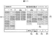
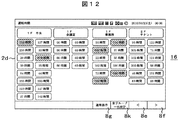
本実施例では、前記詳細情報2表示画面(設定温度表示画面)10で詳細表示ボタン8d或いは後情報ボタン8fを押すと、図6に示す風量表示画面11に移り、更に詳細表示ボタン8d或いは後情報ボタン8fを押す毎に、順次、図7に示す風向表示画面12、図10に示すメンテナンス情報表示画面14、図11に示す圧縮機運転状態表示画面15、図12に示す空調機運転時間表示画面16と切り替わる。このように本実施例によれば、詳細表示ボタン8d或いは後情報ボタン8fを押す毎に、順次、次の画面に遷移させて全空調機グループの運転情報などを1画面に表示できるため、表示したい運転情報はいくらでも表示させていくことができる。また、全てのグループアイコンを一括表示(1つの画面に全グループアイコンを表示)すると共に、各グループのアイコンはコントローラ表示部2dの同じ位置に常に表示させるようにしているので、どの詳細情報表示画面に移っても、瞬時に確認したい空調機グループの運転情報を確認できる。
次に、各詳細情報画面の表示内容を説明する。
運転モード表示画面9では、図4に示すように、各空調機グループの運転モード別に異なる色(本実施例では各グループアイコン8aを異なる模様の網掛けで示すことで色の違いを表現している)でグループアイコン8aを表示している。異運転モード(集中コントローラ2から設定した運転モードと、室外ユニット3の運転サイクル状態により、実際に運転している運転モードが異なる)の場合、両方の運転モードを表示する。図4の異運転モードグループアイコン9aのように、上段に集中コントローラ2から設定した運転モード(異運転モード)の「暖房」を表示し、下段に実際に運転している室外ユニット3の運転モード(実運転モード)の「冷房」を点滅させて表示する。
運転モード表示画面9では、図4に示すように、各空調機グループの運転モード別に異なる色(本実施例では各グループアイコン8aを異なる模様の網掛けで示すことで色の違いを表現している)でグループアイコン8aを表示している。異運転モード(集中コントローラ2から設定した運転モードと、室外ユニット3の運転サイクル状態により、実際に運転している運転モードが異なる)の場合、両方の運転モードを表示する。図4の異運転モードグループアイコン9aのように、上段に集中コントローラ2から設定した運転モード(異運転モード)の「暖房」を表示し、下段に実際に運転している室外ユニット3の運転モード(実運転モード)の「冷房」を点滅させて表示する。
設定温度表示画面10では、図5に示すように、各空調機グループの設定温度が表示される。予め推奨温度を設定することができ、設定温度表示画面10で、冷房運転中に設定温度が冷房推奨温度より低く設定されている、或いは暖房運転中に設定温度が暖房推奨温度より高く設定されていることが確認できる。冷房推奨温度、暖房推奨温度は、図3に示す通常表示画面のメニューボタン8jから図13に示す推奨温度設定画面17に遷移し、共通の画面でまとめて設定できる。
図5において、冷房運転中の空調機グループの設定温度が冷房推奨温度(この例では28℃)より低い場合は、そのグループアイコン8aは通常と異なる色で表示される。図5の画面で冷房推奨温度設定ボタン8hを押すと、冷房推奨温度より低く設定されている空調機グループの設定温度は冷房推奨温度(28℃)に強制的に一括変更され、冷房推奨温度に変更されたグループアイコン8aは通常の色で表示される。
同様に、図5において、暖房運転中の空調機グループの設定温度が暖房推奨温度(この例では20℃)より高い場合は、そのグループアイコン8aを、前記通常の色や前記冷房推奨温度より低い場合の色以外で表示している。図5の画面で暖房推奨温度設定ボタン8iを押すと、暖房推奨温度より高く設定されている空調機グループの設定温度は暖房推奨温度(20℃)に強制的に一括変更され、暖房推奨温度に変更されたグループアイコン8aは通常の色で表示される。
なお、この例では、冷房運転中に設定温度が冷房推奨温度より低い場合、或いは暖房運転中に設定温度が暖房推奨温度より高い場合に異なる色で警告表示しているが、色の代わりにアイコンの点滅などで警告表示するようにしても良い。
また、前記冷房推奨温度設定ボタン8h又は前記暖房推奨温度設定ボタン8iにより強制的に一括変更される空調機グループと、一括変更の対象とはならない空調機グループを予め設定しておくようにすれば、空調管理対象エリアの実情に合わせて柔軟に対応可能となる。
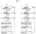
上述した図5の表示方法をフロー図で示すと図17のようになる。即ち、(a)図に示すように、図1、図2に示す集中コントローラ2により冷房推奨温度が設定されている場合、グループの設定温度が前記冷房推奨温度より低く設定されていて、一括変更の対象であるグループのグループアイコン8aは通常色と異なる色で表示される。この状態から図5に示す冷房推奨温度設定ボタン8hを押すと、変更対象となる前記全てのグループの設定温度は前記冷房推奨温度に強制変更されると共にグループアイコン8aも通常色で表示される。同様に、(b)図に示すように、図1、図2に示す集中コントローラ2により暖房推奨温度が設定されている場合、グループの設定温度が前記暖房推奨温度より高く設定されていて、一括変更の対象であるグループのグループアイコン8aは通常色や前記冷房推奨温度より低い場合の色と異なる色で表示される。この状態から図5に示す暖房推奨温度設定ボタン8iを押すと、変更対象となる前記全てのグループの設定温度は前記暖房推奨温度に強制変更されると共にグループアイコン8aも通常色で表示される。図示はしていないが、設定温度は摂氏、華氏の表示の切り替えが可能である。
風量表示画面11では、図6に示すように、各空調機グループの風量別に異なる色でグループアイコン8aを表示している。
図7に示す風向表示画面12では室内ユニット4から吹出される吹出空気の風向角度を表示する。風向角度の設定は図8に示すように、本実施例では8段階に設定でき、集中コントローラ2の表示部2dでの表示も、その設定された風向に表示される。即ち、風向の1段目は最も水平方向に吹出す角度であり、2段目、3段目と次第に下向きに変わり、7段目で最も下向きの吹出す角度となる。更に、自動風向モードも備えており、この自動風向モードでは風向が水平から下向きへ、また下向きから水平へと自動的に風向が変化するモードである。図7に示すように、風向角度が固定されている空調機グループと自動風向モードに設定されているグループ別に異なる色でグループアイコン8aを表示している。
なお、図示はしていないが、室外ユニット3の運転サイクル状態を表示する室外ユニット運転サイクル表示画面も備えており、この室外ユニット運転サイクル表示画面では、室外ユニット3の運転モード(冷房運転モード、暖房運転モード、冷暖自動運転モード、ドライ運転モードなど)を表示する。図4に示す運転モード表示画面9と同様に、運転モード別に異なる色でグループアイコン8aを表示する。
上述した運転モード表示画面9(図4)、設定温度表示画面10(図5)、風量表示画面11(図6)、風向表示画面12(図7)、室外ユニット運転サイクル表示画面(図示せず)において、ある空調機グループのグループアイコン8a、ブロックアイコン8b或いは全グループ一括設定ボタン8kを押すと、図9に示す運転条件設定画面13がポップアップで表示される。この運転条件設定画面13から、その空調機グループ、ブロック或いは全ての空調機グループの運転/停止の設定、運転モードの設定、設定温度の設定、風量の設定、風向の設定、リモコン操作の設定(許可/禁止)や、設定内容の変更ができる。
図10に示すメンテナンス情報表示画面14では、それぞれの空調機グループが、蓄熱運転中、要点検、運転制限中(デマンド設定有り)、要フィルタ清掃、タイマー設定有り、リモコン操作禁止の少なくとも何れかに該当する場合、それらの情報に該当する各種情報アイコン8cが、図に示すように、該当するグループアイコン8aに表示される。その場合、そのグループアイコン8aは通常と異なる色で表示される。
図示はしていないが、上記表示画面の他に、詳細情報表示画面としては、吸込温度表示画面、外気温度表示画面、リモコンサーモ表示画面、リモートサーモ表示画面なども有しており、それぞれの温度を図5に示す設定温度表示画面10と同様に表示する。前記リモコンサーモ表示画面ではリモコンスイッチ周辺の温度を表示し、リモートサーモ表示画面では吸込温度とリモコンサーモの平均値を表示する。
図11に示す圧縮機運転状態表示画面15では、その空調機グループが配管接続されている室外ユニットの圧縮機が作動中の場合にはサーモON、圧縮機停止中はサーモOFFと表示する。サーモONの場合は、そのグループアイコン8aは通常と異なる色で表示される。
図12に示す空調機の運転時間表示画面16では、当該空調機グループの室内ユニット4の、例えば当月の運転時間を「○○時間」或いは「○○h」「○○H」と表示する。図12において、予め運転目安時間(この例では600時間)を設定することができ、その時間を超えた場合は、そのグループアイコン8aは通常と異なる色で表示される。
図示はしていないが、前記室外ユニットの圧縮機のサーモON時間表示画面では、その室外ユニットに接続されている空調機グループにおける当月の圧縮機運転時間を、図12に示す室内ユニットの運転時間表示画面16と同様に表示する。
図13は、冷房推奨温度、暖房推奨温度を設定する画面17を示し、図3に示す画面のメニューボタン3jからこの画面17に遷移させることができ、全空調機グループの冷房推奨温度及び暖房推奨温度を一括して設定することができる。
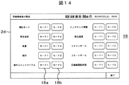
また、図3に示す前記メニューボタン3jから図14に示す詳細情報表示設定画面18に遷移させることもできる。上述した詳細情報表示画面9~16などの表示について、この表示項目は多数設定することが可能であるため、全ての詳細情報表示画面を常に順次表示するようにしたのでは、目的とする情報に辿り着くまでに時間が掛かってしまうことも予想される。そこで、本実施例では、この詳細情報表示設定画面18により、集中コントローラ2を操作する操作者(管理人やサービスマンなど)に応じて必要な情報のみを表示するように、予め表示項目を適宜設定しておくことができるようにしている。即ち、詳細情報表示設定画面18により、表示モード1には詳細情報1、2を表示させ、表示モード2には詳細情報3を表示させるという設定ができるようになっている。
例えば、図14に示す詳細情報表示設定画面18において、運転モード表示画面9(図4)及び設定温度表示画面10(図5)については、表示モード1ボタン18aを押すことで表示モード1での表示を選択し、吸込温度表示画面及びリモコンサーモ表示画面については、表示モード2ボタン18bを押すことで表示モード2での表示を選択する。このようにして各詳細情報の表示の要否を表示モード毎に選択できる。このような選択を行うことで、運転モード表示画面9と設定温度表示画面10を表示モード1で順次表示させ、吸込温度表示画面とリモコンサーモ表示画面を表示モード2で順次表示させることができる。
これにより、表示モード1を監視モードとして、運転モードと設定温度を表示させ、表示モード2を点検モードとして、吸込温度とリモコンサーモを表示させる、という使い方ができる。
この操作をフロー図で示すと図18のようになる。各詳細情報1,2,…,nについて表示或いは非表示を決め、表示する詳細情報については、表示モード1で表示するか、表示モード2で表示するか、或いは両方のモードで表示しないかを設定する。このように設定しておくことで、表示モード1では、このモード1で表示するように設定された詳細情報画面が順次表示され、表示モード2では、このモード2で表示するように設定された詳細情報画面が順次表示されるため、集中コントローラ2を操作する操作者に応じて必要な項目のみを順次表示させることができ、短時間で目的の情報に辿り着くことができる。
なお、前記表示モードの選択は、例えば図3の画面で、詳細表示ボタン8dを1回押すと表示モード1となり、長押しすると表示モード2になるように設定しておくことで可能である。
以上説明したように、本実施例によれば、複数の空調機グループの管理をする集中コントローラの画面上に、各種の詳細情報(空調機グループ毎の運転モードや設定温度等の運転情報の確認、点検の要否やフィルタ清掃の要否等のメンテナンス情報の確認など)を一度にまとめて表示せず、1画面に全空調機グループの情報を示すグループアイコン8aを一定の配置で表示させ、ボタンを1回押す毎に、全空調機グループの運転情報を示すグループアイコン8aを1画面に1種類ずつ前記一定の配置で表示させながら、詳細情報を切り替えて表示させるため、異なる詳細情報を順次同じ位置に表示させることができ、全空調機グループの各種詳細情報を容易に確認することができる空調管理システムを実現することができる。
また、集中コントローラの表示部に運転状態を表示してその確認をした後、運転条件設定画面13のように、設定変更画面をポップアップ表示させることができるので、運転状態確認後、簡単な操作で、即座に設定変更できる効果もある。
更に、各種の詳細情報を1種類ずつ切り替えて表示するため、字や図を大きく表示できる効果もある。
更に、各種の詳細情報を1種類ずつ切り替えて表示するため、字や図を大きく表示できる効果もある。
また、図3に示す通常表示画面8では、1つの空調機グループにでもメンテナンスが必要な機器があれば、コントローラ表示部2dの上部に各種情報アイコン8cとして、「緊急停止中」「要点検」「要フィルタ清掃」などのメンテナンスアイコンも表示するようにしているので、図10に示すメンテナンス情報表示画面14に遷移させることで、どの空調機グループにメンテナンスが必要かを即座に知ることができる。従って、メンテナンス情報の見逃し防止や迅速なメンテナンスが可能になる効果もある。
設定温度表示画面10により、空調機グループ毎に設定されている温度を瞬時に知ることができ、冷やし過ぎ、暖め過ぎを防止し、集中コントローラ2から強制的に設定温度を変更することで、省エネ化にも効果がある。また、ビル管理人など一般ユーザーが必要な運転情報を容易に知ることができるだけでなく、空調機の保守管理をするサービスマンも点検時に必要な運転情報を容易に知ることができる。
上述したように、本実施例によれば、集中コントローラの表示部に、複数の空調機グループの各種運転情報を、操作者が簡単な操作で確認しやすく表示させることが可能となり、空調管理システムにおける設定から外れた運転動作をしている空調機グループを容易に把握して、即座に設定変更が可能な空調管理システムを得ることができる。
1 空調管理システム
2 集中コントローラ(2a:通信部、2b:制御部、2c:入力部、2d:コントローラ表示部、2e:記憶部)
3 室外ユニット(3a:通信部、3b:制御部)
4(41,…,4n) 室内ユニット(4a:通信部、4b:制御部)
5 リモコンスイッチ(リモコン)(5a:通信部、5b:制御部、5c:入力部、5d:表示部、5e:記憶部)
6 制御配線
7 蓄熱ユニット
8 通常表示画面(8a:グループアイコン(グループ表示部)、8b:ブロックアイコン、8c:各種情報アイコン、8d:詳細表示ボタン(グループ運転情報表示手段)、8e:前情報表示ボタン、8f:後情報表示ボタン、8g:通常表示ボタン、8h:冷房推奨温度設定ボタン、8i:暖房推奨温度設定ボタン、8j:メニューボタン、8k:全グループ一括設定ボタン、8l:全グループ一括運転ボタン、8m:全グループ一括停止ボタン)
9 運転モード(詳細情報1)表示画面(9a:異運転モードグループアイコン)
10 設定温度(詳細情報2)表示画面
11 風量表示画面
12 風向表示画面
13 運転条件設定画面
14 メンテナンス情報表示画面
15 圧縮機運転状態表示画面
16 空調機運転時間表示画面
17 推奨温度設定画面
18 詳細情報表示設定画面(18a:表示モード1ボタン、18b:表示モード2ボタン)
20 詳細情報n表示画面
A,B,C,D ブロック
A1,A2,B1,B2,C1,C2,D1,D2 空調機グループ(グループ)
2 集中コントローラ(2a:通信部、2b:制御部、2c:入力部、2d:コントローラ表示部、2e:記憶部)
3 室外ユニット(3a:通信部、3b:制御部)
4(41,…,4n) 室内ユニット(4a:通信部、4b:制御部)
5 リモコンスイッチ(リモコン)(5a:通信部、5b:制御部、5c:入力部、5d:表示部、5e:記憶部)
6 制御配線
7 蓄熱ユニット
8 通常表示画面(8a:グループアイコン(グループ表示部)、8b:ブロックアイコン、8c:各種情報アイコン、8d:詳細表示ボタン(グループ運転情報表示手段)、8e:前情報表示ボタン、8f:後情報表示ボタン、8g:通常表示ボタン、8h:冷房推奨温度設定ボタン、8i:暖房推奨温度設定ボタン、8j:メニューボタン、8k:全グループ一括設定ボタン、8l:全グループ一括運転ボタン、8m:全グループ一括停止ボタン)
9 運転モード(詳細情報1)表示画面(9a:異運転モードグループアイコン)
10 設定温度(詳細情報2)表示画面
11 風量表示画面
12 風向表示画面
13 運転条件設定画面
14 メンテナンス情報表示画面
15 圧縮機運転状態表示画面
16 空調機運転時間表示画面
17 推奨温度設定画面
18 詳細情報表示設定画面(18a:表示モード1ボタン、18b:表示モード2ボタン)
20 詳細情報n表示画面
A,B,C,D ブロック
A1,A2,B1,B2,C1,C2,D1,D2 空調機グループ(グループ)
Claims (14)
- 複数の空調機グループを監視・制御する集中コントローラを備える空調管理システムにおいて、
前記集中コントローラはコントローラ表示部を備え、
前記複数の空調機グループにそれぞれ対応するグループ表示部を前記コントローラ表示部の1つの画面に一括表示させるグループ表示手段と、
前記空調機グループのそれぞれの運転情報を前記コントローラ表示部の1つの画面に一括表示させるグループ運転情報表示手段と、
前記コントローラ表示部に表示させる表示内容を切り替える表示内容切り替え手段と
を備えることを特徴とする空調管理システム。 - 請求項1において、前記コントローラ表示部に通常表示する通常表示画面では、前記複数の空調機グループにそれぞれ対応する前記グループ表示部を1つの画面に一括表示させ、前記表示内容切り替え手段により、各空調機グループの運転情報を前記コントローラ表示部に一括表示させる際には、前記各グループ表示部に対応する各空調機グループの運転情報を同一部分に表示することを特徴とする空調管理システム。
- 部屋毎、フロア毎等に複数の空調機をグループとして扱い、複数の空調機グループを監視・制御する集中コントローラを備える空調管理システムにおいて、
前記集中コントローラはコントローラ表示部を備え、
前記複数の空調機グループにそれぞれ対応するグループアイコンを前記コントローラ表示部の1つの画面に一括表示させ、
前記複数の空調機グループの運転情報を、前記コントローラ表示部の1つの画面に一括表示されている前記グループアイコンの部分に表示させる構成とし、
前記各空調機グループの各種の運転情報を、前記コントローラ表示部に一括表示されている前記グループアイコンの部分に順次表示させていく表示内容切り替えボタン
を備えることを特徴とする空調管理システム。 - 請求項1において、前記複数の空調機グループの運転情報を前記コントローラ表示部の1つの画面に一括表示させている画面には、通常表示画面に戻すための通常表示ボタン及び次の運転情報を表示させるためのボタンを備える、或いは通常表示画面に戻すための通常表示ボタン、次の運転情報を表示させるためのボタン及び1つ前に表示していた画面へ戻すためのボタンを備える構成としていることを特徴とする空調管理システム。
- 請求項1において、前記空調機グループの運転情報表示における運転情報の表示項目は、各空調機グループの「運転モード表示」「設定温度表示」「風量表示」「風向表示」「室外ユニット運転サイクル表示」「蓄熱運転中の表示」「点検要否の表示」「運転制限中の表示」「要フィルタ清掃の表示」「タイマー設定有りの表示」「リモコン操作禁止の表示」「吸込温度表示」「外気温度表示」「リモコンサーモ表示」「リモートサーモ表示」「圧縮機運転状態表示」「空調機運転時間表示」「サーモオン時間表示」のうちの少なくとも1つ以上を表示可能であることを特徴とする空調管理システム。
- 請求項5において、前記表示項目のうち少なくとも2つ以上を表示できるように構成し、且つ前記集中コントローラには複数の表示モードを備え、各表示モードでは前記表示項目の中から予め選択した1以上の表示項目を表示させることを特徴とする空調管理システム。
- 請求項5において、前記表示項目のうち少なくとも「運転モード表示」が可能であり、各空調機グループの運転モードに応じて、それぞれの空調機グループの表示アイコンを運転モードに対応した予め決められた色彩で表示することを特徴とする空調管理システム。
- 請求項5において、前記集中コントローラは、前記表示項目のうち少なくとも「設定温度表示」が可能で且つ各空調機グループの冷房推奨温度及び暖房推奨温度を設定可能に構成され、更に前記空調機グループにもそれらの設定温度を設定可能なリモコンを備え、前記「設定温度表示」画面では、前記集中コントローラで設定された冷房推奨温度より低い温度が設定されている空調機グループ、又は前記暖房推奨温度より高い温度が設定されている空調機グループの表示を他の空調機グループの表示とは異なる警告表示としたことを特徴とする空調管理システム。
- 請求項8において、前記集中コントローラにおける「設定温度表示」では、摂氏、華氏など複数種類の温度表示が可能な構成となっていることを特徴とする空調管理システム。
- 請求項8において、前記集中コントローラには冷房推奨温度設定ボタン及び暖房推奨温度設定ボタンを備え、これらの推奨温度設定ボタンにより、前記警告表示状態にある全て或いは一部の空調機グループの設定温度を強制的に変更可能な構成としていることを特徴とする空調管理システム。
- 請求項10において、前記冷房推奨温度設定ボタン又は暖房推奨温度設定ボタンからの設定温度の一括制御から制御対象除外の空調機グループを設定可能に構成したことを特徴とする空調管理システム。
- 請求項1において、前記コントローラ表示部に表示されている空調機グループに対応する前記グループ表示部又は前記グループアイコンを操作することでその空調機グループの運転条件設定画面がポップアップ表示され、このポップアップ表示された画面から運転条件を変更できる構成としたことを特徴とする空調管理システム。
- 請求項1において、前記各空調機グループは、1つのリモコンスイッチに接続されている複数の室内ユニットをまとめたものであり、一括して監視・制御が可能な構成になっていることを特徴とする空調管理システム。
- 請求項1において、各空調機グループの運転情報を表示中に無操作状態が一定時間経過すると、前記複数の空調機グループにそれぞれ対応する前記グループ表示部を1つの画面に一括表示させる通常表示画面に戻るように構成されていることを特徴とする空調管理システム。
Priority Applications (3)
| Application Number | Priority Date | Filing Date | Title |
|---|---|---|---|
| CN201180009216.9A CN102762929B (zh) | 2010-02-10 | 2011-01-21 | 空调管理系统 |
| JP2011553785A JP5592412B2 (ja) | 2010-02-10 | 2011-01-21 | 空調管理システム |
| EP11742095.0A EP2535655B1 (en) | 2010-02-10 | 2011-01-21 | Air-conditioning system |
Applications Claiming Priority (2)
| Application Number | Priority Date | Filing Date | Title |
|---|---|---|---|
| JP2010-028007 | 2010-02-10 | ||
| JP2010028007 | 2010-02-10 |
Publications (1)
| Publication Number | Publication Date |
|---|---|
| WO2011099346A1 true WO2011099346A1 (ja) | 2011-08-18 |
Family
ID=44367630
Family Applications (1)
| Application Number | Title | Priority Date | Filing Date |
|---|---|---|---|
| PCT/JP2011/051103 Ceased WO2011099346A1 (ja) | 2010-02-10 | 2011-01-21 | 空調管理システム |
Country Status (5)
| Country | Link |
|---|---|
| EP (1) | EP2535655B1 (ja) |
| JP (1) | JP5592412B2 (ja) |
| CN (1) | CN102762929B (ja) |
| TW (1) | TWI489067B (ja) |
| WO (1) | WO2011099346A1 (ja) |
Cited By (14)
| Publication number | Priority date | Publication date | Assignee | Title |
|---|---|---|---|---|
| JP2013164212A (ja) * | 2012-02-10 | 2013-08-22 | Mitsubishi Heavy Ind Ltd | 空調監視装置及び空調監視装置の温度情報表示方法 |
| JP2014199148A (ja) * | 2013-03-29 | 2014-10-23 | ダイキン工業株式会社 | 表示装置 |
| JP2015028407A (ja) * | 2013-07-31 | 2015-02-12 | 日立アプライアンス株式会社 | チラー管理システム、及び、このチラー管理システムを備えたチラー装置。 |
| JP2015040693A (ja) * | 2013-08-23 | 2015-03-02 | 株式会社東芝 | 空調制御システムおよび空調制御装置 |
| WO2015111288A1 (ja) * | 2014-01-21 | 2015-07-30 | 東芝キヤリア株式会社 | 空調機管理装置 |
| JP2016018397A (ja) * | 2014-07-08 | 2016-02-01 | 三菱電機株式会社 | 機器管理装置、機器管理方法及び表示装置 |
| JP2016075462A (ja) * | 2014-10-09 | 2016-05-12 | ダイキン工業株式会社 | 温調システム |
| WO2016103455A1 (ja) * | 2014-12-26 | 2016-06-30 | 三菱電機株式会社 | 空調管理装置 |
| US9779275B2 (en) | 2014-07-03 | 2017-10-03 | Mitsubishi Electric Corporation | Control system, terminal, information setting method, and program |
| JP2017219308A (ja) * | 2012-07-10 | 2017-12-14 | シャープ株式会社 | 電気機器 |
| JP2017227437A (ja) * | 2017-08-30 | 2017-12-28 | 株式会社東芝 | 空調制御システムおよび空調制御装置 |
| JP2018204873A (ja) * | 2017-06-05 | 2018-12-27 | 積水化学工業株式会社 | 空調システムのアドバイス装置 |
| JP2020186844A (ja) * | 2019-05-13 | 2020-11-19 | 三菱電機株式会社 | 空調制御装置、室内機、空調制御システム、空調制御方法、及び、プログラム |
| JP2023121061A (ja) * | 2022-02-18 | 2023-08-30 | 三菱電機株式会社 | 情報出力装置、情報出力システム、情報出力方法、及び、プログラム |
Families Citing this family (14)
| Publication number | Priority date | Publication date | Assignee | Title |
|---|---|---|---|---|
| WO2014128780A1 (ja) * | 2013-02-20 | 2014-08-28 | パナソニック インテレクチュアル プロパティ コーポレーション オブ アメリカ | 携帯情報端末の制御方法及びプログラム |
| CN104442274B (zh) * | 2013-09-24 | 2017-02-01 | 观致汽车有限公司 | 一种车辆空调状态显示控制方法及装置 |
| JP6249702B2 (ja) * | 2013-09-26 | 2017-12-20 | 東芝キヤリア株式会社 | 空気調和機管理システム |
| CN103486703A (zh) * | 2013-10-22 | 2014-01-01 | 王娟 | 智能空调控制器组件 |
| US10291425B2 (en) * | 2014-05-29 | 2019-05-14 | Panasonic Intellectual Property Corporation Of America | Method for controlling terminal apparatus that remotely controls air conditioner, non-transitory recording medium storing program executed by terminal apparatus, recommend method executed by terminal apparatus, and terminal apparatus |
| CN106537053A (zh) * | 2014-06-20 | 2017-03-22 | 江森自控日立空调技术(香港)有限公司 | 显示装置、方法以及程序 |
| JP6472234B2 (ja) * | 2014-12-19 | 2019-02-20 | 三菱重工サーマルシステムズ株式会社 | 空気調和システム |
| EP3269570B1 (en) * | 2016-07-14 | 2019-09-11 | Vestel Elektronik Sanayi ve Ticaret A.S. | Display unit with integrated means for air flow deflection |
| CN106839300B (zh) * | 2017-01-22 | 2020-08-14 | 广东美的制冷设备有限公司 | 空气处理设备的控制装置、方法及系统 |
| US11859844B2 (en) * | 2018-06-13 | 2024-01-02 | Toshiba Carrier Corporation | Air conditioner management device, and air conditioner management screen generation method |
| WO2021171484A1 (ja) * | 2020-02-27 | 2021-09-02 | 東芝キヤリア株式会社 | 設備管理装置および設備管理画面生成方法 |
| CN112413828A (zh) * | 2020-12-09 | 2021-02-26 | 珠海格力电器股份有限公司 | 空调设备的显示画面调节方法和装置 |
| CN113093565B (zh) * | 2021-06-04 | 2021-10-01 | 武汉慧联无限科技有限公司 | 电子设备的控制方法、控制平台、电子设备及存储介质 |
| CN115574420A (zh) * | 2022-09-19 | 2023-01-06 | 青岛海尔空调电子有限公司 | 一种空调自动调控方法、设备、空调和存储介质 |
Citations (5)
| Publication number | Priority date | Publication date | Assignee | Title |
|---|---|---|---|---|
| JPH09257297A (ja) * | 1996-01-18 | 1997-09-30 | Toshiba Corp | 空調管理装置 |
| JPH10160229A (ja) * | 1996-11-28 | 1998-06-19 | Toshiba Corp | 空調用集中管理装置 |
| JP2008157533A (ja) * | 2006-12-22 | 2008-07-10 | Daikin Ind Ltd | 空調管理装置 |
| JP2009036392A (ja) | 2007-07-31 | 2009-02-19 | Toshiba Carrier Corp | 空調管理システム |
| JP2010003292A (ja) * | 2008-05-22 | 2010-01-07 | Daikin Ind Ltd | 群管理装置 |
Family Cites Families (6)
| Publication number | Priority date | Publication date | Assignee | Title |
|---|---|---|---|---|
| JPH02251045A (ja) * | 1989-03-23 | 1990-10-08 | Sanyo Electric Co Ltd | 空気調和機 |
| US6647317B2 (en) * | 2000-09-06 | 2003-11-11 | Hitachi Ltd | Air conditioner management system |
| CN100412456C (zh) * | 2005-06-08 | 2008-08-20 | 海尔集团公司 | 商用空调管理系统及其控制方法 |
| JP2008281300A (ja) * | 2007-05-14 | 2008-11-20 | Hitachi Appliances Inc | 空気調和管理システム,空調ユニット |
| ES2379958T3 (es) * | 2007-10-30 | 2012-05-07 | Lg Electronics Inc. | Acondicionador de aire y procedimiento de funcionamiento del mismo |
| JP4561890B2 (ja) * | 2008-07-01 | 2010-10-13 | ダイキン工業株式会社 | 群管理装置および群管理システム |
-
2011
- 2011-01-11 TW TW100100929A patent/TWI489067B/zh active
- 2011-01-21 EP EP11742095.0A patent/EP2535655B1/en active Active
- 2011-01-21 WO PCT/JP2011/051103 patent/WO2011099346A1/ja not_active Ceased
- 2011-01-21 JP JP2011553785A patent/JP5592412B2/ja active Active
- 2011-01-21 CN CN201180009216.9A patent/CN102762929B/zh active Active
Patent Citations (5)
| Publication number | Priority date | Publication date | Assignee | Title |
|---|---|---|---|---|
| JPH09257297A (ja) * | 1996-01-18 | 1997-09-30 | Toshiba Corp | 空調管理装置 |
| JPH10160229A (ja) * | 1996-11-28 | 1998-06-19 | Toshiba Corp | 空調用集中管理装置 |
| JP2008157533A (ja) * | 2006-12-22 | 2008-07-10 | Daikin Ind Ltd | 空調管理装置 |
| JP2009036392A (ja) | 2007-07-31 | 2009-02-19 | Toshiba Carrier Corp | 空調管理システム |
| JP2010003292A (ja) * | 2008-05-22 | 2010-01-07 | Daikin Ind Ltd | 群管理装置 |
Non-Patent Citations (1)
| Title |
|---|
| See also references of EP2535655A4 |
Cited By (17)
| Publication number | Priority date | Publication date | Assignee | Title |
|---|---|---|---|---|
| JP2013164212A (ja) * | 2012-02-10 | 2013-08-22 | Mitsubishi Heavy Ind Ltd | 空調監視装置及び空調監視装置の温度情報表示方法 |
| JP2017219308A (ja) * | 2012-07-10 | 2017-12-14 | シャープ株式会社 | 電気機器 |
| JP2014199148A (ja) * | 2013-03-29 | 2014-10-23 | ダイキン工業株式会社 | 表示装置 |
| JP2015028407A (ja) * | 2013-07-31 | 2015-02-12 | 日立アプライアンス株式会社 | チラー管理システム、及び、このチラー管理システムを備えたチラー装置。 |
| JP2015040693A (ja) * | 2013-08-23 | 2015-03-02 | 株式会社東芝 | 空調制御システムおよび空調制御装置 |
| JPWO2015111288A1 (ja) * | 2014-01-21 | 2017-03-23 | 東芝キヤリア株式会社 | 空調機管理装置 |
| WO2015111288A1 (ja) * | 2014-01-21 | 2015-07-30 | 東芝キヤリア株式会社 | 空調機管理装置 |
| US9779275B2 (en) | 2014-07-03 | 2017-10-03 | Mitsubishi Electric Corporation | Control system, terminal, information setting method, and program |
| JP2016018397A (ja) * | 2014-07-08 | 2016-02-01 | 三菱電機株式会社 | 機器管理装置、機器管理方法及び表示装置 |
| JP2016075462A (ja) * | 2014-10-09 | 2016-05-12 | ダイキン工業株式会社 | 温調システム |
| WO2016103455A1 (ja) * | 2014-12-26 | 2016-06-30 | 三菱電機株式会社 | 空調管理装置 |
| JPWO2016103455A1 (ja) * | 2014-12-26 | 2017-06-01 | 三菱電機株式会社 | 空調管理装置 |
| JP2018204873A (ja) * | 2017-06-05 | 2018-12-27 | 積水化学工業株式会社 | 空調システムのアドバイス装置 |
| JP2017227437A (ja) * | 2017-08-30 | 2017-12-28 | 株式会社東芝 | 空調制御システムおよび空調制御装置 |
| JP2020186844A (ja) * | 2019-05-13 | 2020-11-19 | 三菱電機株式会社 | 空調制御装置、室内機、空調制御システム、空調制御方法、及び、プログラム |
| JP7361494B2 (ja) | 2019-05-13 | 2023-10-16 | 三菱電機株式会社 | 空調制御装置、空調制御システム、空調制御方法、及び、プログラム |
| JP2023121061A (ja) * | 2022-02-18 | 2023-08-30 | 三菱電機株式会社 | 情報出力装置、情報出力システム、情報出力方法、及び、プログラム |
Also Published As
| Publication number | Publication date |
|---|---|
| EP2535655A1 (en) | 2012-12-19 |
| CN102762929B (zh) | 2016-06-15 |
| EP2535655B1 (en) | 2019-07-17 |
| JPWO2011099346A1 (ja) | 2013-06-13 |
| TWI489067B (zh) | 2015-06-21 |
| EP2535655A4 (en) | 2018-07-04 |
| JP5592412B2 (ja) | 2014-09-17 |
| CN102762929A (zh) | 2012-10-31 |
| TW201200814A (en) | 2012-01-01 |
Similar Documents
| Publication | Publication Date | Title |
|---|---|---|
| JP5592412B2 (ja) | 空調管理システム | |
| CN101389908B (zh) | 空调管理装置 | |
| US9513023B2 (en) | Management apparatus for air-conditioning system | |
| EP2944887B1 (en) | Air conditioning system | |
| EP2400235B1 (en) | Air-conditioning control monitoring device and air-conditioning control monitoring system | |
| US10655882B2 (en) | Remote management system | |
| WO2012153391A1 (ja) | 空調管理装置及びプログラム | |
| JP6793580B2 (ja) | 空調管理装置及び空調管理方法 | |
| JP2008170047A (ja) | 空調機システム、空調機システムの制御方法および集中管理装置 | |
| JP4977547B2 (ja) | 空調管理システム | |
| US8001230B2 (en) | Group management apparatus and group management system | |
| JP4488863B2 (ja) | 空気調和システム | |
| JP6435352B2 (ja) | 空調管理装置およびその表示制御方法 | |
| JP6365078B2 (ja) | 空調システム | |
| JP6637733B2 (ja) | 空調機管理用画面生成装置、およびこれを利用する空調管理装置、空調機管理用画面生成方法 | |
| JP2001235217A (ja) | 空気調和システムの制御装置 | |
| JP2012021709A (ja) | 空調コントローラおよび空調制御方法 | |
| KR102550355B1 (ko) | 빌딩제어 시스템 및 그 제어방법 | |
| JP2752290B2 (ja) | ショーケース等の集中管理装置 | |
| JP6145520B2 (ja) | 空調機管理装置 | |
| WO2016139733A1 (ja) | リモコンシステム | |
| KR102157650B1 (ko) | 공기조화시스템 | |
| CN102906770B (zh) | 资源管理系统 | |
| JP2020030009A (ja) | 空調制御履歴表示装置、空調制御履歴表示方法及びプログラム | |
| JPH0814721A (ja) | ショーケース等の集中管理装置 |
Legal Events
| Date | Code | Title | Description |
|---|---|---|---|
| WWE | Wipo information: entry into national phase |
Ref document number: 201180009216.9 Country of ref document: CN |
|
| 121 | Ep: the epo has been informed by wipo that ep was designated in this application |
Ref document number: 11742095 Country of ref document: EP Kind code of ref document: A1 |
|
| WWE | Wipo information: entry into national phase |
Ref document number: 2011553785 Country of ref document: JP |
|
| NENP | Non-entry into the national phase |
Ref country code: DE |
|
| WWE | Wipo information: entry into national phase |
Ref document number: 2011742095 Country of ref document: EP |