WO2011101975A1 - ハイブリッド車両 - Google Patents
ハイブリッド車両 Download PDFInfo
- Publication number
- WO2011101975A1 WO2011101975A1 PCT/JP2010/052501 JP2010052501W WO2011101975A1 WO 2011101975 A1 WO2011101975 A1 WO 2011101975A1 JP 2010052501 W JP2010052501 W JP 2010052501W WO 2011101975 A1 WO2011101975 A1 WO 2011101975A1
- Authority
- WO
- WIPO (PCT)
- Prior art keywords
- power supply
- control
- control mode
- catalyst
- voltage
- Prior art date
- Legal status (The legal status is an assumption and is not a legal conclusion. Google has not performed a legal analysis and makes no representation as to the accuracy of the status listed.)
- Ceased
Links
Images




Classifications
-
- B—PERFORMING OPERATIONS; TRANSPORTING
- B60—VEHICLES IN GENERAL
- B60K—ARRANGEMENT OR MOUNTING OF PROPULSION UNITS OR OF TRANSMISSIONS IN VEHICLES; ARRANGEMENT OR MOUNTING OF PLURAL DIVERSE PRIME-MOVERS IN VEHICLES; AUXILIARY DRIVES FOR VEHICLES; INSTRUMENTATION OR DASHBOARDS FOR VEHICLES; ARRANGEMENTS IN CONNECTION WITH COOLING, AIR INTAKE, GAS EXHAUST OR FUEL SUPPLY OF PROPULSION UNITS IN VEHICLES
- B60K6/00—Arrangement or mounting of plural diverse prime-movers for mutual or common propulsion, e.g. hybrid propulsion systems comprising electric motors and internal combustion engines
- B60K6/20—Arrangement or mounting of plural diverse prime-movers for mutual or common propulsion, e.g. hybrid propulsion systems comprising electric motors and internal combustion engines the prime-movers consisting of electric motors and internal combustion engines, e.g. HEVs
- B60K6/42—Arrangement or mounting of plural diverse prime-movers for mutual or common propulsion, e.g. hybrid propulsion systems comprising electric motors and internal combustion engines the prime-movers consisting of electric motors and internal combustion engines, e.g. HEVs characterised by the architecture of the hybrid electric vehicle
- B60K6/44—Series-parallel type
- B60K6/445—Differential gearing distribution type
-
- B—PERFORMING OPERATIONS; TRANSPORTING
- B60—VEHICLES IN GENERAL
- B60W—CONJOINT CONTROL OF VEHICLE SUB-UNITS OF DIFFERENT TYPE OR DIFFERENT FUNCTION; CONTROL SYSTEMS SPECIALLY ADAPTED FOR HYBRID VEHICLES; ROAD VEHICLE DRIVE CONTROL SYSTEMS FOR PURPOSES NOT RELATED TO THE CONTROL OF A PARTICULAR SUB-UNIT
- B60W20/00—Control systems specially adapted for hybrid vehicles
- B60W20/10—Controlling the power contribution of each of the prime movers to meet required power demand
- B60W20/15—Control strategies specially adapted for achieving a particular effect
-
- B—PERFORMING OPERATIONS; TRANSPORTING
- B60—VEHICLES IN GENERAL
- B60L—PROPULSION OF ELECTRICALLY-PROPELLED VEHICLES; SUPPLYING ELECTRIC POWER FOR AUXILIARY EQUIPMENT OF ELECTRICALLY-PROPELLED VEHICLES; ELECTRODYNAMIC BRAKE SYSTEMS FOR VEHICLES IN GENERAL; MAGNETIC SUSPENSION OR LEVITATION FOR VEHICLES; MONITORING OPERATING VARIABLES OF ELECTRICALLY-PROPELLED VEHICLES; ELECTRIC SAFETY DEVICES FOR ELECTRICALLY-PROPELLED VEHICLES
- B60L50/00—Electric propulsion with power supplied within the vehicle
- B60L50/10—Electric propulsion with power supplied within the vehicle using propulsion power supplied by engine-driven generators, e.g. generators driven by combustion engines
- B60L50/16—Electric propulsion with power supplied within the vehicle using propulsion power supplied by engine-driven generators, e.g. generators driven by combustion engines with provision for separate direct mechanical propulsion
-
- B—PERFORMING OPERATIONS; TRANSPORTING
- B60—VEHICLES IN GENERAL
- B60L—PROPULSION OF ELECTRICALLY-PROPELLED VEHICLES; SUPPLYING ELECTRIC POWER FOR AUXILIARY EQUIPMENT OF ELECTRICALLY-PROPELLED VEHICLES; ELECTRODYNAMIC BRAKE SYSTEMS FOR VEHICLES IN GENERAL; MAGNETIC SUSPENSION OR LEVITATION FOR VEHICLES; MONITORING OPERATING VARIABLES OF ELECTRICALLY-PROPELLED VEHICLES; ELECTRIC SAFETY DEVICES FOR ELECTRICALLY-PROPELLED VEHICLES
- B60L50/00—Electric propulsion with power supplied within the vehicle
- B60L50/50—Electric propulsion with power supplied within the vehicle using propulsion power supplied by batteries or fuel cells
- B60L50/60—Electric propulsion with power supplied within the vehicle using propulsion power supplied by batteries or fuel cells using power supplied by batteries
- B60L50/61—Electric propulsion with power supplied within the vehicle using propulsion power supplied by batteries or fuel cells using power supplied by batteries by batteries charged by engine-driven generators, e.g. series hybrid electric vehicles
-
- B—PERFORMING OPERATIONS; TRANSPORTING
- B60—VEHICLES IN GENERAL
- B60W—CONJOINT CONTROL OF VEHICLE SUB-UNITS OF DIFFERENT TYPE OR DIFFERENT FUNCTION; CONTROL SYSTEMS SPECIALLY ADAPTED FOR HYBRID VEHICLES; ROAD VEHICLE DRIVE CONTROL SYSTEMS FOR PURPOSES NOT RELATED TO THE CONTROL OF A PARTICULAR SUB-UNIT
- B60W10/00—Conjoint control of vehicle sub-units of different type or different function
- B60W10/04—Conjoint control of vehicle sub-units of different type or different function including control of propulsion units
- B60W10/06—Conjoint control of vehicle sub-units of different type or different function including control of propulsion units including control of combustion engines
-
- B—PERFORMING OPERATIONS; TRANSPORTING
- B60—VEHICLES IN GENERAL
- B60W—CONJOINT CONTROL OF VEHICLE SUB-UNITS OF DIFFERENT TYPE OR DIFFERENT FUNCTION; CONTROL SYSTEMS SPECIALLY ADAPTED FOR HYBRID VEHICLES; ROAD VEHICLE DRIVE CONTROL SYSTEMS FOR PURPOSES NOT RELATED TO THE CONTROL OF A PARTICULAR SUB-UNIT
- B60W10/00—Conjoint control of vehicle sub-units of different type or different function
- B60W10/04—Conjoint control of vehicle sub-units of different type or different function including control of propulsion units
- B60W10/08—Conjoint control of vehicle sub-units of different type or different function including control of propulsion units including control of electric propulsion units, e.g. motors or generators
-
- B—PERFORMING OPERATIONS; TRANSPORTING
- B60—VEHICLES IN GENERAL
- B60W—CONJOINT CONTROL OF VEHICLE SUB-UNITS OF DIFFERENT TYPE OR DIFFERENT FUNCTION; CONTROL SYSTEMS SPECIALLY ADAPTED FOR HYBRID VEHICLES; ROAD VEHICLE DRIVE CONTROL SYSTEMS FOR PURPOSES NOT RELATED TO THE CONTROL OF A PARTICULAR SUB-UNIT
- B60W10/00—Conjoint control of vehicle sub-units of different type or different function
- B60W10/24—Conjoint control of vehicle sub-units of different type or different function including control of energy storage means
-
- B—PERFORMING OPERATIONS; TRANSPORTING
- B60—VEHICLES IN GENERAL
- B60W—CONJOINT CONTROL OF VEHICLE SUB-UNITS OF DIFFERENT TYPE OR DIFFERENT FUNCTION; CONTROL SYSTEMS SPECIALLY ADAPTED FOR HYBRID VEHICLES; ROAD VEHICLE DRIVE CONTROL SYSTEMS FOR PURPOSES NOT RELATED TO THE CONTROL OF A PARTICULAR SUB-UNIT
- B60W10/00—Conjoint control of vehicle sub-units of different type or different function
- B60W10/24—Conjoint control of vehicle sub-units of different type or different function including control of energy storage means
- B60W10/26—Conjoint control of vehicle sub-units of different type or different function including control of energy storage means for electrical energy, e.g. batteries or capacitors
-
- B—PERFORMING OPERATIONS; TRANSPORTING
- B60—VEHICLES IN GENERAL
- B60W—CONJOINT CONTROL OF VEHICLE SUB-UNITS OF DIFFERENT TYPE OR DIFFERENT FUNCTION; CONTROL SYSTEMS SPECIALLY ADAPTED FOR HYBRID VEHICLES; ROAD VEHICLE DRIVE CONTROL SYSTEMS FOR PURPOSES NOT RELATED TO THE CONTROL OF A PARTICULAR SUB-UNIT
- B60W20/00—Control systems specially adapted for hybrid vehicles
-
- B—PERFORMING OPERATIONS; TRANSPORTING
- B60—VEHICLES IN GENERAL
- B60W—CONJOINT CONTROL OF VEHICLE SUB-UNITS OF DIFFERENT TYPE OR DIFFERENT FUNCTION; CONTROL SYSTEMS SPECIALLY ADAPTED FOR HYBRID VEHICLES; ROAD VEHICLE DRIVE CONTROL SYSTEMS FOR PURPOSES NOT RELATED TO THE CONTROL OF A PARTICULAR SUB-UNIT
- B60W20/00—Control systems specially adapted for hybrid vehicles
- B60W20/10—Controlling the power contribution of each of the prime movers to meet required power demand
- B60W20/15—Control strategies specially adapted for achieving a particular effect
- B60W20/16—Control strategies specially adapted for achieving a particular effect for reducing engine exhaust emissions
-
- F—MECHANICAL ENGINEERING; LIGHTING; HEATING; WEAPONS; BLASTING
- F01—MACHINES OR ENGINES IN GENERAL; ENGINE PLANTS IN GENERAL; STEAM ENGINES
- F01N—GAS-FLOW SILENCERS OR EXHAUST APPARATUS FOR MACHINES OR ENGINES IN GENERAL; GAS-FLOW SILENCERS OR EXHAUST APPARATUS FOR INTERNAL-COMBUSTION ENGINES
- F01N3/00—Exhaust or silencing apparatus having means for purifying, rendering innocuous, or otherwise treating exhaust
- F01N3/08—Exhaust or silencing apparatus having means for purifying, rendering innocuous, or otherwise treating exhaust for rendering innocuous
- F01N3/10—Exhaust or silencing apparatus having means for purifying, rendering innocuous, or otherwise treating exhaust for rendering innocuous by thermal or catalytic conversion of noxious components of exhaust
- F01N3/18—Exhaust or silencing apparatus having means for purifying, rendering innocuous, or otherwise treating exhaust for rendering innocuous by thermal or catalytic conversion of noxious components of exhaust characterised by methods of operation; Control
- F01N3/20—Exhaust or silencing apparatus having means for purifying, rendering innocuous, or otherwise treating exhaust for rendering innocuous by thermal or catalytic conversion of noxious components of exhaust characterised by methods of operation; Control specially adapted for catalytic conversion
-
- B—PERFORMING OPERATIONS; TRANSPORTING
- B60—VEHICLES IN GENERAL
- B60L—PROPULSION OF ELECTRICALLY-PROPELLED VEHICLES; SUPPLYING ELECTRIC POWER FOR AUXILIARY EQUIPMENT OF ELECTRICALLY-PROPELLED VEHICLES; ELECTRODYNAMIC BRAKE SYSTEMS FOR VEHICLES IN GENERAL; MAGNETIC SUSPENSION OR LEVITATION FOR VEHICLES; MONITORING OPERATING VARIABLES OF ELECTRICALLY-PROPELLED VEHICLES; ELECTRIC SAFETY DEVICES FOR ELECTRICALLY-PROPELLED VEHICLES
- B60L2270/00—Problem solutions or means not otherwise provided for
- B60L2270/10—Emission reduction
- B60L2270/12—Emission reduction of exhaust
-
- B—PERFORMING OPERATIONS; TRANSPORTING
- B60—VEHICLES IN GENERAL
- B60W—CONJOINT CONTROL OF VEHICLE SUB-UNITS OF DIFFERENT TYPE OR DIFFERENT FUNCTION; CONTROL SYSTEMS SPECIALLY ADAPTED FOR HYBRID VEHICLES; ROAD VEHICLE DRIVE CONTROL SYSTEMS FOR PURPOSES NOT RELATED TO THE CONTROL OF A PARTICULAR SUB-UNIT
- B60W2530/00—Input parameters relating to vehicle conditions or values, not covered by groups B60W2510/00 or B60W2520/00
- B60W2530/12—Catalyst or filter state
-
- B—PERFORMING OPERATIONS; TRANSPORTING
- B60—VEHICLES IN GENERAL
- B60W—CONJOINT CONTROL OF VEHICLE SUB-UNITS OF DIFFERENT TYPE OR DIFFERENT FUNCTION; CONTROL SYSTEMS SPECIALLY ADAPTED FOR HYBRID VEHICLES; ROAD VEHICLE DRIVE CONTROL SYSTEMS FOR PURPOSES NOT RELATED TO THE CONTROL OF A PARTICULAR SUB-UNIT
- B60W2710/00—Output or target parameters relating to a particular sub-units
- B60W2710/08—Electric propulsion units
- B60W2710/086—Power
-
- B—PERFORMING OPERATIONS; TRANSPORTING
- B60—VEHICLES IN GENERAL
- B60W—CONJOINT CONTROL OF VEHICLE SUB-UNITS OF DIFFERENT TYPE OR DIFFERENT FUNCTION; CONTROL SYSTEMS SPECIALLY ADAPTED FOR HYBRID VEHICLES; ROAD VEHICLE DRIVE CONTROL SYSTEMS FOR PURPOSES NOT RELATED TO THE CONTROL OF A PARTICULAR SUB-UNIT
- B60W2710/00—Output or target parameters relating to a particular sub-units
- B60W2710/24—Energy storage means
- B60W2710/242—Energy storage means for electrical energy
- B60W2710/248—Current for loading or unloading
-
- B—PERFORMING OPERATIONS; TRANSPORTING
- B60—VEHICLES IN GENERAL
- B60Y—INDEXING SCHEME RELATING TO ASPECTS CROSS-CUTTING VEHICLE TECHNOLOGY
- B60Y2300/00—Purposes or special features of road vehicle drive control systems
- B60Y2300/47—Engine emissions
- B60Y2300/474—Catalyst warm up
-
- Y—GENERAL TAGGING OF NEW TECHNOLOGICAL DEVELOPMENTS; GENERAL TAGGING OF CROSS-SECTIONAL TECHNOLOGIES SPANNING OVER SEVERAL SECTIONS OF THE IPC; TECHNICAL SUBJECTS COVERED BY FORMER USPC CROSS-REFERENCE ART COLLECTIONS [XRACs] AND DIGESTS
- Y02—TECHNOLOGIES OR APPLICATIONS FOR MITIGATION OR ADAPTATION AGAINST CLIMATE CHANGE
- Y02T—CLIMATE CHANGE MITIGATION TECHNOLOGIES RELATED TO TRANSPORTATION
- Y02T10/00—Road transport of goods or passengers
- Y02T10/10—Internal combustion engine [ICE] based vehicles
- Y02T10/40—Engine management systems
-
- Y—GENERAL TAGGING OF NEW TECHNOLOGICAL DEVELOPMENTS; GENERAL TAGGING OF CROSS-SECTIONAL TECHNOLOGIES SPANNING OVER SEVERAL SECTIONS OF THE IPC; TECHNICAL SUBJECTS COVERED BY FORMER USPC CROSS-REFERENCE ART COLLECTIONS [XRACs] AND DIGESTS
- Y02—TECHNOLOGIES OR APPLICATIONS FOR MITIGATION OR ADAPTATION AGAINST CLIMATE CHANGE
- Y02T—CLIMATE CHANGE MITIGATION TECHNOLOGIES RELATED TO TRANSPORTATION
- Y02T10/00—Road transport of goods or passengers
- Y02T10/60—Other road transportation technologies with climate change mitigation effect
- Y02T10/62—Hybrid vehicles
-
- Y—GENERAL TAGGING OF NEW TECHNOLOGICAL DEVELOPMENTS; GENERAL TAGGING OF CROSS-SECTIONAL TECHNOLOGIES SPANNING OVER SEVERAL SECTIONS OF THE IPC; TECHNICAL SUBJECTS COVERED BY FORMER USPC CROSS-REFERENCE ART COLLECTIONS [XRACs] AND DIGESTS
- Y02—TECHNOLOGIES OR APPLICATIONS FOR MITIGATION OR ADAPTATION AGAINST CLIMATE CHANGE
- Y02T—CLIMATE CHANGE MITIGATION TECHNOLOGIES RELATED TO TRANSPORTATION
- Y02T10/00—Road transport of goods or passengers
- Y02T10/60—Other road transportation technologies with climate change mitigation effect
- Y02T10/70—Energy storage systems for electromobility, e.g. batteries
-
- Y—GENERAL TAGGING OF NEW TECHNOLOGICAL DEVELOPMENTS; GENERAL TAGGING OF CROSS-SECTIONAL TECHNOLOGIES SPANNING OVER SEVERAL SECTIONS OF THE IPC; TECHNICAL SUBJECTS COVERED BY FORMER USPC CROSS-REFERENCE ART COLLECTIONS [XRACs] AND DIGESTS
- Y02—TECHNOLOGIES OR APPLICATIONS FOR MITIGATION OR ADAPTATION AGAINST CLIMATE CHANGE
- Y02T—CLIMATE CHANGE MITIGATION TECHNOLOGIES RELATED TO TRANSPORTATION
- Y02T10/00—Road transport of goods or passengers
- Y02T10/60—Other road transportation technologies with climate change mitigation effect
- Y02T10/7072—Electromobility specific charging systems or methods for batteries, ultracapacitors, supercapacitors or double-layer capacitors
Definitions
- the present invention relates to a hybrid vehicle, and more particularly to a hybrid vehicle that is configured to be electrically heated and includes a catalyst device that purifies exhaust gas from an internal combustion engine.
- a passenger may feel a shock due to a change in torque when the control mode is switched.
- Patent Document 1 discloses a motor control device that can reduce a shock due to an increase in torque when switching from PWM wave voltage driving to rectangular wave voltage driving.
- a vehicle equipped with an internal combustion engine is provided with a catalyst device for purifying exhaust gas. Since this catalyst device does not exhibit an effect unless the temperature rises to some extent, it is arranged near the internal combustion engine so that the temperature immediately rises.
- the purification action is not perfect as long as the catalytic device is not yet warmed immediately after starting the internal combustion engine.
- a traveling motor such as a hybrid vehicle
- the internal combustion engine is repeatedly started and stopped during traveling as necessary. For this reason, the opportunity to start the internal combustion engine in a state where the catalyst device is not warmed increases, and there is a possibility that the time for releasing carbon monoxide, hydrocarbons and the like into the exhaust gas may increase.
- EHC electrically heated catalyst
- EHC sends a large electric power to the catalyst device to raise the temperature of the catalyst device in a short time. Since large power is output from the battery, the voltage of the battery fluctuates. When this voltage fluctuation occurs, depending on the state of the motor drive device, the motor control is greatly affected.
- An object of the present invention is to provide a hybrid vehicle that uses an electrically heated catalyst to improve exhaust gas purification performance and suppress motor torque fluctuations.
- the present invention is a hybrid vehicle, which is an internal combustion engine, a catalyst device configured to be electrically heated and purifying exhaust gas of the internal combustion engine, a motor for driving the vehicle, and a motor for driving the motor
- a drive unit a main power supply device that supplies a power supply voltage to the motor drive unit, a catalyst power supply device that receives power from the main power supply device and supplies heating power to the catalyst device, a motor drive unit, and a catalyst power supply device
- a control device for controlling The control device has a first control mode and a second control mode, which is more resistant to fluctuations in the power supply voltage than the first control mode, as modes for controlling the motor drive unit.
- the control device controls the motor drive unit in the second control mode in advance.
- the motor drive unit includes an inverter for driving the motor, and a voltage converter provided between the main power supply device and the inverter.
- the first control mode includes a mode in which the voltage converter is controlled so that the power supply voltage of the main power supply device is directly applied to the inverter.
- the second control mode includes a mode in which the voltage converter is controlled so as to convert the power supply voltage of the main power supply device and apply it to the inverter (60).
- the voltage converter includes a reactor having one end connected to the positive electrode of the main power supply device, and a switching element provided between the other end of the reactor and the power supply node of the inverter.
- the control device fixes the switching element in the conductive state in the first control mode, and switches the switching element in the second control mode.
- control device changes the operation mode of the motor drive unit from the first control mode to the second control mode when the first control mode is executed when a request to heat the catalyst device is generated. After that, power supply from the catalyst power supply device to the catalyst device is started.
- control device stops the power supply from the catalyst power supply device to the catalyst device when the second control mode is executed when the request to heat the catalyst device disappears, and then the motor drive unit The operation mode is returned from the second control mode to the first control mode.
- control device temporarily changes the operation mode of the motor drive unit from the first control mode to the second control mode when the first control mode is executed when a request to heat the catalyst device is generated. After changing to the control mode, power supply from the catalyst power supply device to the catalyst device is started.
- control device temporarily changes the operation mode of the motor drive unit from the first control mode to the second control mode when the first control mode is executed when the request to heat the catalyst device disappears. After changing to the control mode, power supply from the catalyst power supply device to the catalyst device is stopped.
- the motor drive unit includes an inverter for driving the motor, and a voltage converter provided between the main power supply device and the inverter.
- the first control mode includes a mode for performing either rectangular wave control or overmodulation control on the inverter.
- the second control mode includes a mode in which sinusoidal pulse width modulation control is performed on the inverter.
- FIG. 1 is an overall block diagram of a hybrid vehicle according to a first embodiment.
- 2 is a circuit diagram for explaining the circuit configuration of the vehicle 1 in more detail.
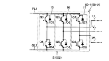
- FIG. FIG. 3 is a circuit diagram showing a detailed configuration of inverters 60-1 and 60-2 in FIG.
- FIG. 3 is a circuit diagram showing a detailed configuration of the voltage converter 90 of FIG. 2. It is a figure explaining the control system used with the motor drive system according to the embodiment of the present invention. It is a flowchart explaining the selection method of a control system. It is a figure for demonstrating switching of the control system corresponding to a motor condition.
- 3 is a flowchart for illustrating control executed by ECU 150 in FIG. 2.
- FIG. 2 is a circuit diagram for explaining the circuit configuration of the vehicle 1 in more detail.
- FIG. FIG. 3 is a circuit diagram showing a detailed configuration of inverters 60-1 and 60-2 in FIG.
- FIG. 3 is a circuit diagram showing a detailed configuration of the voltage converter 90 of FIG. 2.
- FIG. 3 is a waveform diagram showing an example of a transition of a state change of a vehicle according to control executed in the first embodiment.
- FIG. 10 is an operation waveform diagram for illustrating the operation of the modification of the first embodiment.
- FIG. 6 is a diagram showing a configuration of a hybrid vehicle 1A of a second embodiment. 6 is a flowchart for illustrating control executed by ECU 150A in a second embodiment.
- FIG. 1 is an overall block diagram of a hybrid vehicle according to the first embodiment.
- hybrid vehicle 1 includes an engine 10, a motor generator MG1, a motor generator MG2, a power split mechanism 40, a speed reducer 50, and drive wheels 80.
- the engine 10 is an internal combustion engine that generates a driving force for rotating a crankshaft by combustion energy generated when an air-fuel mixture sucked into a combustion chamber is combusted.
- Motor generator MG1 and motor generator MG2 are AC motors, for example, three-phase AC synchronous motors.
- Hybrid vehicle 1 travels by driving force output from at least one of engine 10 and motor generator MG2.
- the driving force generated by the engine 10 is divided into two paths by the power split mechanism 40. That is, one is a path through which the driving force is transmitted to the drive wheels 80 via the reduction gear 50, and the other is a path through which the driving force is transmitted to the motor generator MG1.
- the power split mechanism 40 includes a planetary gear composed of a sun gear, a pinion gear, a carrier, and a ring gear.
- the pinion gear engages with the sun gear and the ring gear.
- the carrier supports the pinion gear so as to be capable of rotating, and is connected to the crankshaft of the engine 10.
- the sun gear is coupled to the rotation shaft of motor generator MG1.
- the ring gear is connected to the rotation shaft of motor generator MG2 and speed reducer 50.
- engine 10, motor generator MG1 and motor generator MG2 are connected via power split mechanism 40, so that the rotational speeds of engine 10, motor generator MG1 and motor generator MG2 are connected in a straight line in the nomograph. Become a relationship.
- Hybrid vehicle 1 further includes a motor drive unit 75.
- Motor drive unit 75 includes an inverter 60, a smoothing capacitor C ⁇ b> 1, a voltage converter 90, and a power storage device 70.
- the inverter 60 controls driving of the motor generator MG1 and the motor generator MG2.
- Motor generator MG1 generates power using the power of engine 10 divided by power split device 40. Electric power generated by motor generator MG 1 is converted from alternating current to direct current by inverter 60 and stored in power storage device 70.
- Motor generator MG2 generates a driving force using at least one of the electric power stored in power storage device 70 and the electric power generated by motor generator MG1. Then, the driving force of motor generator MG ⁇ b> 2 is transmitted to driving wheels 80 via reduction gear 50.
- the drive wheel 80 is shown as a front wheel, but the rear wheel may be driven by the motor generator MG2 instead of the front wheel or together with the front wheel.
- motor generator MG2 When the vehicle is braked, the motor generator MG2 is driven by the drive wheels 80 via the speed reducer 50, and the motor generator MG2 operates as a generator. Thereby, motor generator MG2 also functions as a regenerative brake that converts the kinetic energy of the vehicle into electric power. Electric power generated by motor generator MG ⁇ b> 2 is stored in power storage device 70.
- the inverter 60 includes an inverter 60-1 and an inverter 60-2. Inverter 60-1 and inverter 60-2 are connected in parallel to voltage converter 90.
- the inverter 60-1 is provided between the voltage converter 90 and the motor generator MG1. Inverter 60-1 controls driving of motor generator MG1 based on a control signal S1 from an electronic control unit (Electronic Control Unit, hereinafter referred to as "ECU") 150.
- ECU Electronic Control Unit
- Inverter 60-2 is provided between voltage converter 90 and motor generator MG2. Inverter 60-2 controls driving of motor generator MG2 based on control signal S2 from ECU 150.
- Voltage converter 90 performs voltage conversion between power storage device 70 and inverter 60.
- Voltage converter 90 boosts the voltage of power storage device 70 (more precisely, the voltage between power supply line PL0 and ground line GL0) to a target voltage value indicated by control signal S3 from ECU 150, and inverter 60 Output to.
- the voltage hereinafter also referred to as “high-voltage DC voltage VH” or simply “voltage VH”
- VH high-voltage DC voltage
- the smoothing capacitor C1 is connected between the power supply wiring PL1 and the ground wiring GL1.
- the smoothing capacitor C1 smoothes the DC voltage VH on the high voltage side.
- the exhaust gas discharged from the engine 10 is discharged to the atmosphere through the exhaust passage 130.
- an electrically heated catalyst (EHC) 140 is provided in the middle of the exhaust passage 130.
- the EHC 140 is configured such that a catalyst for purifying exhaust gas can be electrically heated.
- the EHC 140 is connected to the EHC power source 100 and heats the catalyst with the power supplied from the EHC power source 100.
- Various known EHCs can be applied to the EHC 140.
- the EHC power supply 100 is provided between the EHC 140 and the power storage device 70.
- EHC power supply 100 is connected to power storage device 70 in parallel with voltage converter 90.
- EHC power supply 100 adjusts the electric power supplied from power storage device 70 to EHC 140 based on control signal S5 from ECU 150. For example, when the temperature Tehc of the EHC 140 is lower than a predetermined temperature and the purification performance of the EHC 140 is lower than the target level, the ECU 150 controls the EHC power supply 100 to supply electric power from the power storage device 70 to the EHC 140. Thereby, the EHC 140 is driven and the catalyst provided in the EHC 140 is heated, so that the purification performance is improved.
- the hybrid vehicle 1 further includes a voltage sensor 121, rotational speed sensors 122, 123, and 124, and a temperature sensor 125.
- the voltage sensor 121 detects the voltage VB of the power storage device 70.
- the rotational speed sensors 122, 123, and 124 detect the rotational speed Ne of the engine 10, the rotational speed Nm1 of the motor generator MG1, and the rotational speed Nm2 of the motor generator MG2, respectively.
- the temperature sensor 125 detects the temperature Tehc of the EHC 140. Each of these sensors transmits a detection result to ECU 150.
- the ECU 150 includes a CPU (Central Processing Unit) (not shown) and a memory, and is configured to execute predetermined arithmetic processing based on a map and a program stored in the memory. Alternatively, at least a part of the ECU 150 may be configured to execute predetermined numerical / logical operation processing by hardware such as an electronic circuit.
- a CPU Central Processing Unit
- ECU 150 generates the above-described control signals S1 to S5 based on information from each sensor and the like, and outputs the generated control signals S1 to S5 to each device. For example, ECU 150 sets torque command value Tgcom of motor generator MG1 and torque command value Tmcom of motor generator MG2 based on information from each sensor and the like, and a control signal for matching torque Tg of motor generator MG1 with torque command value Tgcom. A control signal S2 for causing S1 and torque Tm of motor generator MG2 to coincide with torque command value Tmcom is generated and output to inverter 60-1 and inverter 60-2, respectively. The ECU 150 sets a command value for the fuel injection amount of the engine 10 based on information from each sensor, etc., and generates a control signal S4 that matches the actual fuel injection amount of the engine 10 with the command value. Output to.
- FIG. 2 is a circuit diagram for explaining the circuit configuration of the vehicle 1 in more detail.
- vehicle 1 includes a power storage device 70 that is a main power supply device, a motor drive unit 75, a smoothing capacitor C1, a voltage sensor 121, an engine 10, motor generators MG1 and MG2, and power splitting.
- a mechanism 40, a wheel 2, an EHC power supply 100, and an ECU 150 are included.
- the motor drive unit 75 includes a voltage converter 90, a smoothing capacitor CH, inverters 60-1 and 60-2, and a voltage sensor 13.
- the smoothing capacitor C1 is connected between the power supply wiring PL0 and the ground wiring GL0.
- the voltage converter 90 boosts the voltage between the terminals of the smoothing capacitor C1.
- the smoothing capacitor CH smoothes the voltage boosted by the voltage converter 90.
- the voltage sensor 13 detects the inter-terminal voltage VH of the smoothing capacitor CH and outputs it to the ECU 150.
- Inverter 60-1 converts the DC voltage supplied from voltage converter 90 into a three-phase AC voltage and outputs the same to motor generator MG1.
- Inverter 60-2 converts the DC voltage applied from voltage converter 90 into a three-phase AC voltage and outputs the same to motor generator MG2.
- the power split mechanism 40 is a mechanism that is coupled to the engine 10 and the motor generators MG1 and MG2 and distributes power between them.
- a planetary gear mechanism having three rotating shafts of a sun gear, a planetary carrier, and a ring gear can be used.
- rotation of two of the three rotation shafts is determined, rotation of the other one rotation shaft is forcibly determined.
- the rotating shaft of motor generator MG2 is coupled to wheel 2 by a reduction gear and a differential gear (not shown). Further, a reduction gear for the rotation shaft of motor generator MG2 may be further incorporated in power split device 40.
- the voltage sensor 121 measures the voltage VB between the terminals of the power storage device 70.
- a current sensor that detects a current flowing through the power storage device 70 is provided.
- a secondary battery such as a lead storage battery, a nickel metal hydride battery, or a lithium ion battery, or a large-capacity capacitor such as an electric double layer capacitor can be used.
- the ground wiring GL1 is connected to the ground wiring GL0 in the voltage converter 90 as will be described later.
- the inverter 60-1 is connected to the power supply wiring PL1 and the ground wiring GL1. Inverter 60-1 receives the boosted voltage from voltage converter 90 and drives motor generator MG1 to start engine 10, for example. Inverter 60-1 returns the electric power generated by motor generator MG1 to the voltage converter 90 by the power transmitted from engine 10. At this time, voltage converter 90 is controlled by ECU 150 to operate as a step-down circuit.
- Current sensor 24 detects the current flowing through motor generator MG1 as motor current value MCRT1, and outputs motor current value MCRT1 to ECU 150.
- the inverter 60-2 is connected to the power supply wiring PL1 and the ground wiring GL1 in parallel with the inverter 60-1.
- Inverter 60-2 converts the DC voltage output from voltage converter 90 into a three-phase AC voltage and outputs the same to motor generator MG2 driving wheel 2.
- Inverter 60-2 returns the electric power generated in motor generator MG2 to voltage converter 90 in accordance with regenerative braking.
- voltage converter 90 is controlled by ECU 150 to operate as a step-down circuit.
- Current sensor 25 detects the current flowing through motor generator MG2 as motor current value MCRT2, and outputs motor current value MCRT2 to ECU 150.
- ECU 150 receives each torque command value and rotation speed of motor generators MG1, MG2, each value of voltages VB, VL, VH, motor current values MCRT1, MCRT2, and EHC start signal EHCON.
- control signal S1 instructs the inverter 60-1 to drive the DC voltage output from the voltage converter 90 to an AC voltage for driving the motor generator MG1, or the AC signal generated by the motor generator MG1.
- This is a control signal for performing a regeneration instruction for converting the voltage into a DC voltage and returning it to the voltage converter 90 side.
- control signal S2 instructs the inverter 60-2 to drive to convert a DC voltage into an AC voltage for driving the motor generator MG2, or converts the AC voltage generated by the motor generator MG2 into a DC voltage. And a regenerative instruction for returning to the voltage converter 90 side.
- FIG. 3 is a circuit diagram showing a detailed configuration of inverters 60-1 and 60-2 in FIG.
- inverter 60-1 includes a U-phase arm 15, a V-phase arm 16, and a W-phase arm 17.
- U-phase arm 15, V-phase arm 16, and W-phase arm 17 are connected in parallel between power supply line PL1 and ground line GL1.
- U-phase arm 15 includes IGBT elements Q3 and Q4 connected in series between power supply line PL1 and ground line GL1, and diodes D3 and D4 connected in parallel with IGBT elements Q3 and Q4, respectively.
- the cathode of diode D3 is connected to the collector of IGBT element Q3, and the anode of diode D3 is connected to the emitter of IGBT element Q3.
- the cathode of diode D4 is connected to the collector of IGBT element Q4, and the anode of diode D4 is connected to the emitter of IGBT element Q4.
- V-phase arm 16 includes IGBT elements Q5 and Q6 connected in series between power supply wiring PL1 and ground wiring GL1, and diodes D5 and D6 connected in parallel with IGBT elements Q5 and Q6, respectively.
- the cathode of diode D5 is connected to the collector of IGBT element Q5, and the anode of diode D5 is connected to the emitter of IGBT element Q5.
- the cathode of diode D6 is connected to the collector of IGBT element Q6, and the anode of diode D6 is connected to the emitter of IGBT element Q6.
- W-phase arm 17 includes IGBT elements Q7 and Q8 connected in series between power supply wiring PL1 and ground wiring GL1, and diodes D7 and D8 connected in parallel with IGBT elements Q7 and Q8, respectively.
- the cathode of diode D7 is connected to the collector of IGBT element Q7, and the anode of diode D7 is connected to the emitter of IGBT element Q7.
- the cathode of diode D8 is connected to the collector of IGBT element Q8, and the anode of diode D8 is connected to the emitter of IGBT element Q8.
- each phase arm is connected to each phase end of each phase coil of motor generator MG1. That is, motor generator MG1 is a three-phase permanent magnet synchronous motor, and one end of each of three coils of U, V, and W phases is connected to a neutral point.
- the other end of the U-phase coil is connected to a line UL drawn from the connection node of IGBT elements Q3 and Q4.
- the other end of the V-phase coil is connected to a line VL drawn from the connection node of IGBT elements Q5 and Q6.
- the other end of the W-phase coil is connected to a line WL drawn from the connection node of IGBT elements Q7 and Q8.
- inverter 60-2 in FIG. 2 is also different in that it is connected to motor generator MG2, but the internal circuit configuration is the same as that of inverter 60-1, and detailed description thereof will not be repeated.
- FIG. 3 shows that the control signal S1 is given to the inverter. In the case of the inverter 60-2, the control signal S2 is input instead of the control signal S1.
- FIG. 4 is a circuit diagram showing a detailed configuration of the voltage converter 90 of FIG. 2 and 4, voltage converter 90 includes a reactor L1 having one end connected to power supply line PL0, and IGBT elements Q1, Q2 connected in series between power supply line PL1 and ground line GL1. And diodes D1, D2 connected in parallel to IGBT elements Q1, Q2, respectively.
- the ground wiring GL1 and the ground wiring GL0 are connected inside the voltage converter 90.
- reactor L1 The other end of reactor L1 is connected to the emitter of IGBT element Q1 and the collector of IGBT element Q2.
- the cathode of diode D1 is connected to the collector of IGBT element Q1, and the anode of diode D1 is connected to the emitter of IGBT element Q1.
- the cathode of diode D2 is connected to the collector of IGBT element Q2, and the anode of diode D2 is connected to the emitter of IGBT element Q2.
- the ON / OFF of the IGBT elements Q1, Q2 is controlled by the control signal S3 given from the ECU 150 in FIG.
- FIG. 5 is a diagram illustrating a control method used in the motor drive system according to the embodiment of the present invention.
- the motor drive unit 75 switches between three control modes for voltage conversion in the inverters 60-1 and 60-2.
- the three control modes are control modes of sine wave PWM control, overmodulation PWM control, and rectangular wave voltage control.
- the sine wave PWM control is used as a general PWM control method, and the switching element in each phase arm is turned on / off by comparing the voltage between a sine wave voltage command value and a carrier wave (typically a triangular wave). Control according to. As a result, for a set of a high level period corresponding to the on period of the upper arm element and a low level period corresponding to the on period of the lower arm element, the duty is set so that the fundamental wave component becomes a sine wave within a certain period. The ratio is controlled. As is well known, in the sine wave PWM control, the fundamental wave component amplitude can be increased only up to 0.61 times the inverter input voltage.
- an AC motor is applied to one pulse of a rectangular wave with a ratio of the high level period to the low level period of 1: 1 corresponding to the case where the PWM duty is maintained at the maximum value within the above-mentioned fixed period. To do. As a result, the modulation rate is increased to 0.78.
- the overmodulation PWM control is to perform the same PWM control as the sine wave PWM control after being distorted so as to reduce the amplitude of the carrier wave.
- the modulation factor can be increased to a range of 0.61 to 0.78 by distorting the fundamental wave component.
- the boosted voltage by the voltage converter 90 that is, the system voltage VH needs to be set higher than this motor required voltage (induced voltage).
- the boosted voltage by the voltage converter 90 that is, the system voltage has a limit value (VH maximum voltage).
- a rectangular wave voltage control system as a kind of field weakening control is applied while maintaining the system voltage VH. Since the amplitude of the fundamental wave component is fixed during the rectangular wave voltage control, the torque control is executed by the voltage phase control of the rectangular wave pulse based on the deviation between the actual torque value obtained by power calculation and the torque command value.
- FIG. 6 is a flowchart for explaining a control method selection method.
- the ECU 150 receives the torque command values of the motor generators MG1 and MG2 calculated by the host ECU (not shown) based on the vehicle request output according to the accelerator opening, etc. (step S100). Based on a preset map or the like, the required motor voltage (induced voltage) is calculated from the torque command values of motor generators MG1 and MG2 and the rotational speed (step S110), and further, the maximum required motor voltage and system voltage are calculated.
- step S120 it is determined which of the rectangular wave voltage control method and the PWM control method (sine wave PWM control method / overmodulation PWM control method) is to be used to control the motor (step S120). . Whether to use the sine wave PWM control method or the overmodulation PWM control method when applying the PWM control method is determined according to the modulation rate range of the voltage command value according to the vector control. According to the control flow, an appropriate control method is selected from the plurality of control methods shown in FIG. 5 according to the operating conditions of motor generators MG1 and MG2.
- FIG. 7 is a diagram for explaining switching of the control method corresponding to the motor condition.
- sine wave PWM control is used in the low rotational speed range A1 to reduce torque fluctuation
- overmodulation PWM control and high rotational speed are used in the middle rotational speed range A2.
- rectangular wave voltage control is applied.
- the output of motor generators MG1 and MG2 is improved by applying overmodulation PWM control and rectangular wave voltage control. As described above, which one of the control modes shown in FIG. 5 is used is determined within the range of the realizable modulation rate.
- FIG. 8 is a flowchart for explaining the control executed by the ECU 150 in FIG. The processing of this flowchart is called and executed from a predetermined main routine every predetermined time or every time a predetermined condition is satisfied.
- ECU 150 determines in step S11 whether or not there is an EHC ON request based on signal EHCON.
- step S11 If it is determined in step S11 that there is an EHC ON request, the process proceeds to step S12. In step S12, it is determined whether or not upper arm ON control is being performed in voltage converter 90.
- the upper arm ON control is control for fixing the IGBT element Q1 in FIG. 4 to the ON state and fixing the IGBT element Q2 to the OFF state.
- the power supply wiring PL0 and the power supply wiring PL1 are connected.
- switching loss of the IGBT element can be eliminated by executing the upper arm ON control.
- the EHC is turned ON / OFF
- the voltage VB of the power supply wiring PL0 fluctuates. Therefore, if this is performed during the upper arm ON control execution, the voltage VH of the power supply wiring PL1 connected to the inverters 60-1 and 60-2 Will also vary. As a result, the torque fluctuation of the motor may occur.
- step S12 determines whether the upper arm ON control is being performed. If it is determined in step S12 that the upper arm ON control is being performed, the process proceeds to step S13, where the upper arm ON control is prohibited and the voltage converter 90 is operated. Thereby, the voltage VH is stabilized at the target value. Thereafter, in step S14, the EHC power supply 100 is activated to supply power to the EHC.
- step S12 when it is determined in step S12 that the upper arm ON control is not being performed, the voltage converter 90 is in operation as shown in step S15. Therefore, since voltage VH is stabilized by voltage converter 90, in this state, EHC power supply 100 is activated and power is supplied to EHC in step S16.
- step S17 the operation of the EHC power supply 100 is stopped and the power supply to the EHC is stopped.
- step S17 the operation of the EHC power supply 100 is stopped and the power supply to the EHC is stopped.
- FIG. 9 is a waveform diagram showing an example of a change in the state change of the vehicle according to the control executed in the first embodiment.
- signal EHCON (indicating an EHC operation request) is in an OFF state
- voltage converter 90 is in an upper arm ON control state
- EHC energization is in an OFF state
- an engine is also in an OFF state. Has been.
- the engine is started at time t4.
- the catalyst is sufficiently heated and normally exhibits a catalytic function.
- the signal EHCON changes from the ON state to the OFF state.
- the engine may be operating or stopped.
- the exhaust gas is not discharged, so that heating of the catalyst is unnecessary, and the signal EHCON is also changed to the OFF state.
- the signal EHCON changes to the OFF state when the temperature of the catalyst can be maintained by exhaust heat of the exhaust gas.
- the EHC energization is first controlled to be OFF at time t12. At this time, since the voltage converter 90 is executing voltage conversion, voltage fluctuation of the voltage VH is suppressed.
- the voltage converter 90 is controlled during voltage conversion to stabilize the voltage VH, so that torque fluctuations of the motor generators MG1 and MG2 are suppressed.
- FIG. 10 is an operation waveform diagram for explaining the operation of the modification of the first embodiment.
- the operation of the voltage converter 90 is temporarily changed from the upper arm ON state to the voltage conversion state, and then the EHC operation is started or stopped.
- the signal EHCON (indicating an EHC operation request) is controlled to be in the OFF state
- the voltage converter 90 is controlled to be in the upper arm ON control state
- the energization of the EHC is controlled to be in the OFF state.
- the temporary prohibition of the upper arm ON control of the voltage converter 90 is released again, and after time t4, the voltage converter 90 is controlled to the upper arm ON control state.
- the voltage VH can be stabilized by the voltage converter 90 when the EHC state changes with the largest voltage change.
- the switching loss of the voltage converter 90 can be reduced by performing the upper arm ON control again during the subsequent EHC energization.
- upper arm ON control of voltage converter 90 is permitted at time t14, and upper arm ON control is executed depending on the state of the vehicle at that time.
- FIG. 11 is a diagram showing a configuration of a hybrid vehicle 1A of the second embodiment.
- vehicle 1A includes a power storage device 70 that is a main power supply device, a motor drive unit 75A, a smoothing capacitor C1, motor generators MG1 and MG2, an EHC power supply 100, and an ECU 150A.
- the motor drive unit 75 includes a smoothing capacitor CH, inverters 60-1 and 60-2, and a voltage sensor 13.
- ECU 150A controls in advance a state in which motor drive unit 75A is less likely to cause torque fluctuations when the state of EHC power supply 100 is changed.
- Sine wave PWM control has the best controllability among the inverter control methods described in FIG. Therefore, when the control is being performed by the overmodulation PWM control or the rectangular wave voltage control method, it is preferable to change the inverter control method to the sine wave PWM control method and then turn ON / OFF the EHC.
- FIG. 12 is a flowchart for illustrating control executed by ECU 150A in the second embodiment. The processing of this flowchart is called and executed from a predetermined main routine every predetermined time or every time a predetermined condition is satisfied.
- ECU 150 determines in step S51 whether there is an EHC ON request based on signal EHCON.
- step S51 If it is determined in step S51 that there is an EHC ON request, the process proceeds to step S52.
- step S52 it is determined whether or not rectangular wave voltage control or overmodulation PWM control is being performed in inverters 60-1 and 60-2. Since these control methods are inferior in controllability compared to sinusoidal PWM control, torque fluctuations are likely to occur when the voltage VH varies.
- step S52 if it is determined in step S52 that the rectangular wave voltage control or the overmodulation PWM control is being performed, the process proceeds to step S53, and ECU 150A prohibits the rectangular wave voltage control and the overmodulation PWM control and inhibits inverter 60- Drive 1,60-2. That is, ECU 150A extends and applies rotation speed region A1 of FIG. 7 to rotation speed regions A2 and A3, and operates inverters 60-1 and 60-2 by a sine wave PWM control method. As a result, the controllability of the motor is improved, so that the influence on the motor control when the voltage VB fluctuates can be reduced. Thereafter, in step S54, the EHC power supply 100 is activated to supply power to the EHC.
- step S52 if it is determined in step S52 that the rectangular wave voltage control or the overmodulation PWM control is not being performed, the inverters 60-1 and 60-2 are operating in the sine wave PWM control method as shown in step S55. Therefore, in this state, the EHC power supply 100 is activated in step S56 to supply power to the EHC.
- step S51 If it is determined in step S51 that there is no EHC ON request, the process proceeds to step S57.
- step S57 the operation of the EHC power supply 100 is stopped and the power supply to the EHC is stopped.
- step S58 the rectangular wave voltage control and overmodulation PWM control of the inverters 60-1 and 60-2 are permitted.
- step S59 When any one of steps S54, S56, and S58 is completed, control is transferred to the main routine in step S59.
- the influence of the EHC state change on the motor control can be reduced by changing the inverter control method before the EHC state change. Can do.
- the inverter control method may be temporarily changed as in the case described with reference to FIG. 10 of the first embodiment. Further, even in a configuration having a voltage converter, the control method of the inverter may be changed instead of the control change of the voltage converter. The voltage converter control change and the inverter control method change may be combined.
- the hybrid vehicle of the present embodiment is configured to be capable of being electrically heated, engine 10, EHC 140 that purifies exhaust gas from engine 10, a vehicle travel motor (MG1 or MG2), A motor driving unit 75 for driving the motor (MG1 or MG2), a power storage device 70 that supplies power to the motor driving unit 75, and an EHC power source that receives power from the power storage device 70 and supplies heating power to the EHC 140 100 and an ECU 150 that controls the motor drive unit 75 and the EHC power supply 100.
- ECU 150 has a first control mode and a second control mode, which is more resistant to fluctuations in power supply voltage than the first control mode, as modes for controlling motor drive unit 75. When the electric power supplied from the EHC power supply 100 to the EHC 140 is changed, the ECU 150 controls the motor driving unit 75 in the second control mode in advance.
- motor drive unit 75 includes an inverter 60 for driving a motor (MG1 or MG2) and a voltage converter 90 provided between power storage device 70 and inverter 60.
- the first control mode includes a mode (upper arm ON control mode) for controlling voltage converter 90 so that power supply voltage of power storage device 70 is applied to inverter 60 as it is.
- the second control mode includes a mode in which voltage converter 90 is controlled so that the power supply voltage of power storage device 70 is converted to voltage and supplied to inverter 60.
- voltage converter 90 includes a reactor L ⁇ b> 1 having one end connected to the positive electrode of power storage device 70, and an IGBT provided between the other end of reactor L ⁇ b> 1 and the power supply node of inverter 60. And element Q1.
- ECU 150 fixes IGBT element Q1 in the conductive state in the first control mode, and switches IGBT element Q1 in the second control mode.
- the ECU 150 changes the operation mode of the motor drive unit 75 to the first when the first control mode is executed when a request to heat the EHC 140 is generated.
- the control mode is changed to the second control mode, and then power supply from the EHC power supply 100 to the EHC 140 is started.
- the ECU 150 stops power supply from the EHC power supply 100 to the EHC 140 when the second control mode is executed when the request to heat the EHC 140 disappears. Thereafter, the operation mode of the motor drive unit 75 is returned from the second control mode to the first control mode.
- the ECU 150 temporarily sets the operation mode of the motor drive unit 75 to the first mode when the first control mode is executed when a request to heat the EHC 140 is generated.
- the control mode is changed to the second control mode, and then power supply from the EHC power supply 100 to the EHC 140 is started.
- ECU 150 temporarily sets the operation mode of motor drive unit 75 to the first mode when the first control mode is executed when the request to heat EHC 140 disappears.
- the control mode is changed to the second control mode, and then the power supply from the EHC power supply 100 to the EHC 140 is stopped.
- motor drive unit 75 includes an inverter 60 for driving the motor, and a voltage converter 90 provided between power storage device 70 and inverter 60.
- the first control mode includes a mode in which either rectangular wave control or overmodulation control is performed on the inverter 60.
- the second control mode includes a mode in which sinusoidal pulse width modulation control is performed on inverter 60.
- 1,1A hybrid vehicle 2 wheels, 10 engine, 13, 21, 121, 121 voltage sensor, 15 U phase arm, 16 V phase arm, 17 W phase arm, 24, 25 current sensor, 40 power split mechanism, 50 deceleration Machine, 60 inverter, 70 power storage device, 75, 75A motor drive unit, 80 drive wheel, 90 voltage converter, 100 EHC power supply, 122, 123, 124 rotation speed sensor, 125 temperature sensor, 130 exhaust passage, C1, CH smoothing capacitor , D1 to D8 diode, GL0, GL1 ground wiring, L1 reactor, MG1, MG2 motor generator, PL0, PL1 power supply wiring, Q1 to Q8 IGBT elements.
Landscapes
- Engineering & Computer Science (AREA)
- Chemical & Material Sciences (AREA)
- Mechanical Engineering (AREA)
- Transportation (AREA)
- Combustion & Propulsion (AREA)
- Power Engineering (AREA)
- Automation & Control Theory (AREA)
- Sustainable Development (AREA)
- Life Sciences & Earth Sciences (AREA)
- Sustainable Energy (AREA)
- Chemical Kinetics & Catalysis (AREA)
- Health & Medical Sciences (AREA)
- Toxicology (AREA)
- General Engineering & Computer Science (AREA)
- Electric Propulsion And Braking For Vehicles (AREA)
- Hybrid Electric Vehicles (AREA)
- Exhaust Gas After Treatment (AREA)
- Control Of Vehicle Engines Or Engines For Specific Uses (AREA)
Abstract
Description
図1は、実施の形態1に従うハイブリッド車の全体ブロック図である。
図2を参照して、車両1は、主電源装置である蓄電装置70と、モータ駆動部75と、平滑コンデンサC1と、電圧センサ121と、エンジン10と、モータジェネレータMG1,MG2と、動力分割機構40と、車輪2と、EHC電源100と、ECU150とを含む。
図2、図3を参照して、インバータ60-1は、U相アーム15と、V相アーム16と、W相アーム17とを含む。U相アーム15,V相アーム16,およびW相アーム17は、電源配線PL1と接地配線GL1との間に並列に接続される。
図2、図4を参照して、電圧コンバータ90は、一方端が電源配線PL0に接続されるリアクトルL1と、電源配線PL1と接地配線GL1との間に直列に接続されるIGBT素子Q1,Q2と、IGBT素子Q1,Q2にそれぞれ並列に接続されるダイオードD1,D2とを含む。接地配線GL1と接地配線GL0とは、電圧コンバータ90の内部で接続されている。
図6のフローチャートに示されるように、図示しない上位ECUによって、アクセル開度等に従う車両要求出力に基づきモータジェネレータMG1,MG2のトルク指令値が算出される(ステップS100)のを受けて、ECU150は、予め設定されたマップ等に基づいて、モータジェネレータMG1,MG2のトルク指令値および回転数からモータ必要電圧(誘起電圧)を算出し(ステップS110)、さらに、モータ必要電圧とシステム電圧の最大値(VH最大電圧)との関係に従って、矩形波電圧制御方式およびPWM制御方式(正弦波PWM制御方式/過変調PWM制御方式)のいずれを適用してモータ制御を行なうかを決定する(ステップS120)。PWM制御方式の適用時に、正弦波PWM制御方式および過変調PWM制御方式のいずれを用いるかについては、ベクトル制御に従う電圧指令値の変調率範囲に応じて決定する。上記制御フローに従って、モータジェネレータMG1,MG2の運転条件に従って、図5に示した複数の制御方式のうちから適正な制御方式が選択される。
制御方式の選択の結果、図7に示されるように、低回転数域A1ではトルク変動を小さくするために正弦波PWM制御が用いられ、中回転数域A2では過変調PWM制御、高回転数域A3では矩形波電圧制御が適用される。特に、過変調PWM制御および矩形波電圧制御の適用により、モータジェネレータMG1,MG2の出力向上が実現される。このように、図5に示した制御モードのいずれを用いるかについては、実現可能な変調率の範囲内で決定される。
図10は、実施の形態1の変形例の動作を説明するための動作波形図である。
図11は、実施の形態2のハイブリッド車両1Aの構成を示した図である。
図1を参照して、本実施の形態のハイブリッド車両は、エンジン10と、電気加熱可能に構成され、エンジン10の排気ガスを浄化するEHC140と、車両走行用のモータ(MG1またはMG2)と、モータ(MG1またはMG2)を駆動するためのモータ駆動部75と、モータ駆動部75に電源電圧を供給する蓄電装置70と、蓄電装置70から電力を受け、EHC140に加熱用電力を供給するEHC電源100と、モータ駆動部75およびEHC電源100を制御するECU150とを備える。ECU150は、モータ駆動部75を制御するモードとして、第1の制御モードと、第1の制御モードよりも電源電圧の変動に強い第2の制御モードとを有する。ECU150は、EHC電源100からEHC140に供給する電力を変更する場合には、予めモータ駆動部75を第2の制御モードで制御する。
Claims (8)
- 内燃機関(10)と、
電気加熱可能に構成され、前記内燃機関(10)の排気ガスを浄化する触媒装置(140)と、
車両走行用のモータ(MG1またはMG2)と、
前記モータ(MG1またはMG2)を駆動するためのモータ駆動部(75)と、
前記モータ駆動部(75)に電源電圧を供給する主電源装置(70)と、
前記主電源装置(70)から電力を受け、前記触媒装置(140)に加熱用電力を供給する触媒用電源装置(100)と、
前記モータ駆動部(75)および前記触媒用電源装置(100)を制御する制御装置(150)とを備え、
前記制御装置(150)は、前記モータ駆動部(75)を制御するモードとして、第1の制御モードと、前記第1の制御モードよりも前記電源電圧の変動に強い第2の制御モードとを有し、
前記制御装置(150)は、前記触媒用電源装置(100)から前記触媒装置(140)に供給する電力を変更する場合には、予め前記モータ駆動部(75)を前記第2の制御モードで制御する、ハイブリッド車両。 - 前記モータ駆動部(75)は、
前記モータ(MG1またはMG2)を駆動するためのインバータ(60)と、
前記主電源装置(70)と前記インバータ(60)との間に設けられる電圧コンバータ(90)とを含み、
前記第1の制御モードは、前記主電源装置(70)の前記電源電圧をそのまま前記インバータ(60)に与えるように前記電圧コンバータ(90)を制御するモードを含み、
前記第2の制御モードは、前記主電源装置(70)の前記電源電圧を電圧変換して前記インバータ(60)に与えるように前記電圧コンバータ(90)を制御するモードを含む、請求の範囲第1項に記載のハイブリッド車両。 - 前記電圧コンバータ(90)は、
前記主電源装置(70)の正極に一方端が接続されるリアクトル(L1)と、
前記リアクトル(L1)の他方端と前記インバータ(60)の電源ノードとの間に設けられるスイッチング素子(Q1)とを含み、
前記制御装置(150)は、前記第1の制御モードにおいて前記スイッチング素子(Q1)を導通状態に固定し、前記第2の制御モードにおいては前記スイッチング素子(Q1)をスイッチングさせる、請求の範囲第2項に記載のハイブリッド車両。 - 前記制御装置(150)は、前記触媒装置(140)を加熱する要求が発生した場合に前記第1の制御モードが実行されていたときには、前記モータ駆動部(75)の動作モードを前記第1の制御モードから前記第2の制御モードに変更し、その後前記触媒用電源装置(100)から前記触媒装置(140)への電力供給を開始する、請求の範囲第2項に記載のハイブリッド車両。
- 前記制御装置(150)は、前記触媒装置(140)を加熱する要求が消えた場合に前記第2の制御モードが実行されていたときには、前記触媒用電源装置(100)から前記触媒装置(140)への電力供給を停止し、その後前記モータ駆動部(75)の動作モードを前記第2の制御モードから前記第1の制御モードに戻す、請求の範囲第4項に記載のハイブリッド車両。
- 前記制御装置(150)は、前記触媒装置(140)を加熱する要求が発生した場合に前記第1の制御モードが実行されていたときには、前記モータ駆動部(75)の動作モードを一時的に前記第1の制御モードから前記第2の制御モードに変更し、その後前記触媒用電源装置(100)から前記触媒装置(140)への電力供給を開始する、請求の範囲第2項に記載のハイブリッド車両。
- 前記制御装置(150)は、前記触媒装置(140)を加熱する要求が消えた場合に前記第1の制御モードが実行されていたときには、前記モータ駆動部(75)の動作モードを一時的に前記第1の制御モードから前記第2の制御モードに変更し、その後前記触媒用電源装置(100)から前記触媒装置(140)への電力供給を停止する、請求の範囲第6項に記載のハイブリッド車両。
- 前記モータ駆動部(75)は、
前記モータを駆動するためのインバータ(60)と、
前記主電源装置(70)と前記インバータ(60)との間に設けられる電圧コンバータ(90)とを含み、
前記第1の制御モードは、前記インバータ(60)に対して矩形波制御または過変調制御のいずれかの制御を行なうモードを含み、
前記第2の制御モードは、前記インバータ(60)に対して正弦波パルス幅変調制御を行なうモードを含む、請求の範囲第1項に記載のハイブリッド車両。
Priority Applications (5)
| Application Number | Priority Date | Filing Date | Title |
|---|---|---|---|
| CN201080064111.9A CN102762427B (zh) | 2010-02-19 | 2010-02-19 | 混合动力车辆 |
| PCT/JP2010/052501 WO2011101975A1 (ja) | 2010-02-19 | 2010-02-19 | ハイブリッド車両 |
| JP2012500427A JP5310935B2 (ja) | 2010-02-19 | 2010-02-19 | ハイブリッド車両 |
| US13/574,169 US8565957B2 (en) | 2010-02-19 | 2010-02-19 | Hybrid vehicle |
| EP10846112.0A EP2537726A4 (en) | 2010-02-19 | 2010-02-19 | HYBRID VEHICLE |
Applications Claiming Priority (1)
| Application Number | Priority Date | Filing Date | Title |
|---|---|---|---|
| PCT/JP2010/052501 WO2011101975A1 (ja) | 2010-02-19 | 2010-02-19 | ハイブリッド車両 |
Publications (1)
| Publication Number | Publication Date |
|---|---|
| WO2011101975A1 true WO2011101975A1 (ja) | 2011-08-25 |
Family
ID=44482593
Family Applications (1)
| Application Number | Title | Priority Date | Filing Date |
|---|---|---|---|
| PCT/JP2010/052501 Ceased WO2011101975A1 (ja) | 2010-02-19 | 2010-02-19 | ハイブリッド車両 |
Country Status (5)
| Country | Link |
|---|---|
| US (1) | US8565957B2 (ja) |
| EP (1) | EP2537726A4 (ja) |
| JP (1) | JP5310935B2 (ja) |
| CN (1) | CN102762427B (ja) |
| WO (1) | WO2011101975A1 (ja) |
Cited By (1)
| Publication number | Priority date | Publication date | Assignee | Title |
|---|---|---|---|---|
| US8490740B2 (en) | 2010-03-15 | 2013-07-23 | Toyota Jidosha Kabushiki Kaisha | Vehicle |
Families Citing this family (12)
| Publication number | Priority date | Publication date | Assignee | Title |
|---|---|---|---|---|
| US9021793B2 (en) * | 2011-06-06 | 2015-05-05 | GM Global Technology Operations LLC | Method for converting constituent gases in an internal combustion engine exhaust gas mixture and a vehicle incorporating the same |
| WO2013008328A1 (ja) * | 2011-07-14 | 2013-01-17 | トヨタ自動車株式会社 | 車両の駆動装置 |
| CN102922981B (zh) * | 2012-10-29 | 2015-06-03 | 长城汽车股份有限公司 | 一种混合动力驱动装置及车辆 |
| ITMI20130146A1 (it) * | 2013-02-01 | 2014-08-02 | Novia E | Sistema per il controllo della coppia motrice di un veicolo avente due ruote motrici azionate da motori distinti |
| US9744960B2 (en) * | 2013-05-29 | 2017-08-29 | Nissan Motor Co., Ltd. | Control system for a plug-in hybrid vehicle |
| JP2015105045A (ja) * | 2013-11-29 | 2015-06-08 | トヨタ自動車株式会社 | 電力変換器の制御装置 |
| TWI621551B (zh) * | 2015-04-20 | 2018-04-21 | 國立高雄科技大學 | 燃料電池混合動力控制方法 |
| FR3040158B1 (fr) * | 2015-08-17 | 2017-09-15 | Peugeot Citroen Automobiles Sa | Procede de repartition d’une consigne d’assistance de couple d’une fonction de depollution thermique pour un vehicule hybride |
| JP6828705B2 (ja) * | 2018-03-12 | 2021-02-10 | トヨタ自動車株式会社 | 車両の制御装置 |
| KR102661558B1 (ko) | 2019-06-19 | 2024-04-26 | 비테스코 테크놀로지스 게엠베하 | 배기가스 후처리 시스템 및 내연기관의 배기가스 후처리 시스템을 제어하는 방법 |
| DE102020202192A1 (de) * | 2020-02-20 | 2021-08-26 | Vitesco Technologies GmbH | Verfahren zum Betrieb eines Heizkatalysators und Heizkatalysatorsteuersystem |
| US11708065B2 (en) | 2021-02-19 | 2023-07-25 | Ford Global Technologies, Llc | Electrical power control method |
Citations (7)
| Publication number | Priority date | Publication date | Assignee | Title |
|---|---|---|---|---|
| JPH06101459A (ja) | 1992-09-21 | 1994-04-12 | Nissan Motor Co Ltd | 内燃機関の回転速度制御装置 |
| JP2004192820A (ja) | 2002-12-06 | 2004-07-08 | Toyota Motor Corp | 燃料電池自動車 |
| JP2005160183A (ja) * | 2003-11-25 | 2005-06-16 | Mitsubishi Electric Corp | 同期電動機駆動装置及び同期電動機駆動装置の制御方法及び冷凍冷蔵庫及び空気調和機 |
| JP2006197791A (ja) | 2004-12-15 | 2006-07-27 | Nissan Motor Co Ltd | モータ制御装置 |
| JP2008014186A (ja) * | 2006-07-04 | 2008-01-24 | Toyota Motor Corp | 高電圧供給装置 |
| JP2008043179A (ja) * | 2006-07-13 | 2008-02-21 | Denso Corp | 電気自動車の制御装置 |
| JP2009171643A (ja) * | 2008-01-10 | 2009-07-30 | Toyota Motor Corp | 電圧変換装置ならびにそれを備えた負荷駆動装置および電動車両 |
Family Cites Families (9)
| Publication number | Priority date | Publication date | Assignee | Title |
|---|---|---|---|---|
| US5345761A (en) * | 1993-12-02 | 1994-09-13 | Ford Motor Company | Energy management system for hybrid vehicle |
| JP2982746B2 (ja) * | 1997-06-06 | 1999-11-29 | トヨタ自動車株式会社 | ハイブリッド車両の内燃機関制御装置 |
| JP4365424B2 (ja) * | 2007-03-30 | 2009-11-18 | トヨタ自動車株式会社 | ハイブリッド車両の制御装置 |
| JP4183013B1 (ja) * | 2007-05-15 | 2008-11-19 | トヨタ自動車株式会社 | 車両およびその制御方法 |
| JP4483976B2 (ja) * | 2008-05-12 | 2010-06-16 | トヨタ自動車株式会社 | ハイブリッド車両およびハイブリッド車両の制御方法 |
| JP2009274478A (ja) * | 2008-05-12 | 2009-11-26 | Toyota Motor Corp | ハイブリッド車両 |
| US20100109437A1 (en) * | 2008-11-05 | 2010-05-06 | Fattic Gerald T | Battery pack disconnection method for a hybrid vehicle |
| US8727050B2 (en) * | 2009-02-25 | 2014-05-20 | GM Global Technology Operations LLC | System and method for controlling an electrically heated catalyst for a hybrid vehicle |
| US8413423B2 (en) * | 2009-09-01 | 2013-04-09 | GM Global Technologies Operations LLC | Catalyst temperature control systems and methods for hybrid vehicles |
-
2010
- 2010-02-19 US US13/574,169 patent/US8565957B2/en active Active
- 2010-02-19 JP JP2012500427A patent/JP5310935B2/ja active Active
- 2010-02-19 WO PCT/JP2010/052501 patent/WO2011101975A1/ja not_active Ceased
- 2010-02-19 EP EP10846112.0A patent/EP2537726A4/en not_active Withdrawn
- 2010-02-19 CN CN201080064111.9A patent/CN102762427B/zh not_active Expired - Fee Related
Patent Citations (7)
| Publication number | Priority date | Publication date | Assignee | Title |
|---|---|---|---|---|
| JPH06101459A (ja) | 1992-09-21 | 1994-04-12 | Nissan Motor Co Ltd | 内燃機関の回転速度制御装置 |
| JP2004192820A (ja) | 2002-12-06 | 2004-07-08 | Toyota Motor Corp | 燃料電池自動車 |
| JP2005160183A (ja) * | 2003-11-25 | 2005-06-16 | Mitsubishi Electric Corp | 同期電動機駆動装置及び同期電動機駆動装置の制御方法及び冷凍冷蔵庫及び空気調和機 |
| JP2006197791A (ja) | 2004-12-15 | 2006-07-27 | Nissan Motor Co Ltd | モータ制御装置 |
| JP2008014186A (ja) * | 2006-07-04 | 2008-01-24 | Toyota Motor Corp | 高電圧供給装置 |
| JP2008043179A (ja) * | 2006-07-13 | 2008-02-21 | Denso Corp | 電気自動車の制御装置 |
| JP2009171643A (ja) * | 2008-01-10 | 2009-07-30 | Toyota Motor Corp | 電圧変換装置ならびにそれを備えた負荷駆動装置および電動車両 |
Non-Patent Citations (1)
| Title |
|---|
| See also references of EP2537726A4 * |
Cited By (1)
| Publication number | Priority date | Publication date | Assignee | Title |
|---|---|---|---|---|
| US8490740B2 (en) | 2010-03-15 | 2013-07-23 | Toyota Jidosha Kabushiki Kaisha | Vehicle |
Also Published As
| Publication number | Publication date |
|---|---|
| JP5310935B2 (ja) | 2013-10-09 |
| US20120303200A1 (en) | 2012-11-29 |
| EP2537726A4 (en) | 2013-09-04 |
| CN102762427A (zh) | 2012-10-31 |
| CN102762427B (zh) | 2014-11-26 |
| JPWO2011101975A1 (ja) | 2013-06-17 |
| EP2537726A1 (en) | 2012-12-26 |
| US8565957B2 (en) | 2013-10-22 |
Similar Documents
| Publication | Publication Date | Title |
|---|---|---|
| JP5310935B2 (ja) | ハイブリッド車両 | |
| JP5423898B2 (ja) | 電動車両およびその制御方法 | |
| JP4513907B2 (ja) | ハイブリッド車両 | |
| JP4179351B2 (ja) | 電源システムおよびそれを備えた車両、電源システムの制御方法、ならびに電源システムの制御をコンピュータに実行させるためのプログラムを記録したコンピュータ読取可能な記録媒体 | |
| JP4365424B2 (ja) | ハイブリッド車両の制御装置 | |
| JP5332740B2 (ja) | モータ駆動制御装置 | |
| WO2008146941A1 (ja) | ハイブリッド車両、ハイブリッド車両の制御方法およびその制御方法をコンピュータに実行させるためのプログラムを記録したコンピュータ読取可能な記録媒体 | |
| WO2011114417A1 (ja) | 車両 | |
| WO2013051152A1 (ja) | 電圧変換装置の制御装置及び制御方法 | |
| JP5807524B2 (ja) | 電圧変換装置の制御装置 | |
| JP2011109852A (ja) | 電源システムの制御装置およびそれを搭載する車両 | |
| JP2010114987A (ja) | 電動機駆動装置およびそれを備えた電動車両 | |
| JP2011109850A (ja) | 電源システムの制御装置およびそれを搭載する車両 | |
| JP5926172B2 (ja) | 交流電動機の制御システム | |
| JP2009274478A (ja) | ハイブリッド車両 | |
| JP5332726B2 (ja) | 駆動装置 | |
| JP2012182912A (ja) | 電動車両およびその制御方法 | |
| JP2012180003A (ja) | 電動車両およびその制御方法 | |
| JP2010115056A (ja) | 電源システムおよび車両 | |
| JP2010273512A (ja) | モータ駆動システムおよび車両 | |
| JP2013060041A (ja) | ハイブリッド車両およびその制御方法 | |
| JP5618012B2 (ja) | 電圧変換装置の制御装置及び制御方法 | |
| WO2011086657A1 (ja) | ハイブリッド車両の制御装置および制御方法 | |
| JP2010183673A (ja) | 車両駆動装置 | |
| JP6036649B2 (ja) | 車両制御装置 |
Legal Events
| Date | Code | Title | Description |
|---|---|---|---|
| WWE | Wipo information: entry into national phase |
Ref document number: 201080064111.9 Country of ref document: CN |
|
| 121 | Ep: the epo has been informed by wipo that ep was designated in this application |
Ref document number: 10846112 Country of ref document: EP Kind code of ref document: A1 |
|
| DPE1 | Request for preliminary examination filed after expiration of 19th month from priority date (pct application filed from 20040101) | ||
| WWE | Wipo information: entry into national phase |
Ref document number: 2012500427 Country of ref document: JP |
|
| WWE | Wipo information: entry into national phase |
Ref document number: 13574169 Country of ref document: US |
|
| NENP | Non-entry into the national phase |
Ref country code: DE |
|
| WWE | Wipo information: entry into national phase |
Ref document number: 2010846112 Country of ref document: EP |