WO2011104757A1 - 数値制御装置 - Google Patents
数値制御装置 Download PDFInfo
- Publication number
- WO2011104757A1 WO2011104757A1 PCT/JP2010/001286 JP2010001286W WO2011104757A1 WO 2011104757 A1 WO2011104757 A1 WO 2011104757A1 JP 2010001286 W JP2010001286 W JP 2010001286W WO 2011104757 A1 WO2011104757 A1 WO 2011104757A1
- Authority
- WO
- WIPO (PCT)
- Prior art keywords
- axis
- correction amount
- error
- rotation
- rotation axis
- Prior art date
- Legal status (The legal status is an assumption and is not a legal conclusion. Google has not performed a legal analysis and makes no representation as to the accuracy of the status listed.)
- Ceased
Links
Images


Classifications
-
- G—PHYSICS
- G05—CONTROLLING; REGULATING
- G05B—CONTROL OR REGULATING SYSTEMS IN GENERAL; FUNCTIONAL ELEMENTS OF SUCH SYSTEMS; MONITORING OR TESTING ARRANGEMENTS FOR SUCH SYSTEMS OR ELEMENTS
- G05B19/00—Program-control systems
- G05B19/02—Program-control systems electric
- G05B19/18—Numerical control [NC], i.e. automatically operating machines, in particular machine tools, e.g. in a manufacturing environment, so as to execute positioning, movement or co-ordinated operations by means of program data in numerical form
- G05B19/404—Numerical control [NC], i.e. automatically operating machines, in particular machine tools, e.g. in a manufacturing environment, so as to execute positioning, movement or co-ordinated operations by means of program data in numerical form characterised by control arrangements for compensation, e.g. for backlash, overshoot, tool offset, tool wear, temperature, machine construction errors, load, inertia
-
- G—PHYSICS
- G05—CONTROLLING; REGULATING
- G05B—CONTROL OR REGULATING SYSTEMS IN GENERAL; FUNCTIONAL ELEMENTS OF SUCH SYSTEMS; MONITORING OR TESTING ARRANGEMENTS FOR SUCH SYSTEMS OR ELEMENTS
- G05B2219/00—Program-control systems
- G05B2219/30—Nc systems
- G05B2219/49—Nc machine tool, till multiple
- G05B2219/49344—Surface, 5-axis surface machining
-
- G—PHYSICS
- G05—CONTROLLING; REGULATING
- G05B—CONTROL OR REGULATING SYSTEMS IN GENERAL; FUNCTIONAL ELEMENTS OF SUCH SYSTEMS; MONITORING OR TESTING ARRANGEMENTS FOR SUCH SYSTEMS OR ELEMENTS
- G05B2219/00—Program-control systems
- G05B2219/30—Nc systems
- G05B2219/50—Machine tool, machine tool null till machine tool work handling
- G05B2219/50152—Align axis cylinder, tube with rotation axis machine
-
- G—PHYSICS
- G05—CONTROLLING; REGULATING
- G05B—CONTROL OR REGULATING SYSTEMS IN GENERAL; FUNCTIONAL ELEMENTS OF SUCH SYSTEMS; MONITORING OR TESTING ARRANGEMENTS FOR SUCH SYSTEMS OR ELEMENTS
- G05B2219/00—Program-control systems
- G05B2219/30—Nc systems
- G05B2219/50—Machine tool, machine tool null till machine tool work handling
- G05B2219/50297—Compensation of positioning error due to a-axis, b-axis tool rotation
Definitions
- the present invention relates to a numerical control device that controls a machine tool having a straight axis and a rotary shaft, and more particularly, a numerical control device that can perform high-precision machining by correcting the influence of errors of the straight axis and the rotary shaft.
- a numerical control device that controls a machine tool having a straight axis and a rotary shaft, and more particularly, a numerical control device that can perform high-precision machining by correcting the influence of errors of the straight axis and the rotary shaft.
- the translation error amount generated at the tool tip position is calculated.
- a method has been proposed in which the three rectilinear axes are driven to positions corrected by the translation error amount (see, for example, Patent Document 2).
- the present invention has been made in view of the above problems, and by moving the tool tip position to an error-free position, the tool posture in a direction that can be corrected without difficulty is maintained in an error-free posture, thereby achieving high accuracy.
- An object of the present invention is to provide a numerical controller capable of realizing machining.
- a numerical control device is a numerical control device that controls a machine tool having a straight axis and a rotation axis, and calculates a position correction amount of the straight axis from a translation error and an attitude error depending on the movement of the rotation axis.
- a position addition correction amount calculation means for calculating a position correction amount of the shaft.
- the numerical control device is a numerical control device for controlling a machine tool having a straight axis and a rotary axis, and calculates a position correction amount of the straight axis from a translation error and a posture error depending on the motion of the straight axis.
- a rotation axis angle correction amount calculation means for calculating the angle correction amount of the rotation axis from a part of the posture error depending on the motion of the rectilinear axis, and the rotation axis correction amount
- a position addition correction amount calculation means for calculating the position correction amount of the rectilinear axis.
- the numerical control device is a numerical control device for controlling a machine tool having a straight axis and a rotary axis, and calculates a position correction amount of the straight axis from a translation error and a posture error depending on the motion of the straight axis.
- the rotation axis dependent position correction amount calculation means Depends on the straight axis dependent position correction amount calculation means, the rotation axis dependent position correction amount calculation means for calculating the position correction amount of the straight axis from the translation error and posture error depending on the motion of the rotation axis, and depends on the motion of the straight axis
- a rotation axis angle correction amount calculating means for calculating an angle correction amount of the rotation axis from a part of the posture error to be performed and a part of the posture error depending on the motion of the rotation axis, and a linear axis corresponding to the rotation axis correction amount.
- a position addition correction amount calculation means for calculating the position correction amount.
- a numerical control device that realizes high-precision machining by moving a tool tip position to a position having no error and maintaining a tool position in a direction that can be corrected without difficulty in an error-free position. Can be provided.
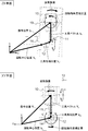
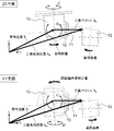
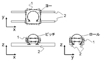
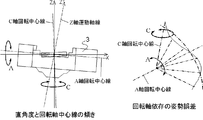
- Example 1 of this invention It is a block diagram of the numerical control apparatus concerning Example 1 of this invention. It is a mimetic diagram explaining a table turning type 5 axis processing machine to which the present invention is applied. It is a schematic diagram explaining a mixed type 5-axis processing machine to which the present invention is applied. It is a schematic diagram explaining a spindle head turning type 5-axis processing machine to which the present invention is applied. It is a schematic diagram explaining the attitude
- FIG. 1 is a configuration diagram of a portion where the straight axis position correction amount and the rotation axis angle correction amount are calculated in the numerical controller according to the first embodiment.
- the hardware configuration of the numerical controller in the first embodiment is a general configuration including a CPU, a memory, and the like, and components other than the storage units 4 and 5 (memory) (straight axis dependent position correction amount calculation)
- the means 6, the rotation axis dependent position correction amount calculation means 7, the rotation axis angle correction amount calculation means 8, the position addition correction amount calculation means 9, etc.) are mainly constituted by software.
- the linear axis dependent translation error / linear axis dependent attitude error storage unit 4 (hereinafter referred to as the linear axis dependent error storage unit) provides the linear axis command with the translation error and attitude error depending on the linear axis motion. Save as numerical data corresponding to the position.
- the linear axis dependent error storage unit provides the linear axis command with the translation error and attitude error depending on the linear axis motion.
- the linear axis dependent error storage unit provides the linear axis command with the translation error and attitude error depending on the linear axis motion.
- the linear axis dependent error storage unit provides the linear axis command with the translation error and attitude error depending on the linear axis motion.
- numerical data corresponding to the position In a machine with 3 linear axes (X axis, Y axis, and Z axis), there may be 6 components xtx, xty, xtz, xrx, xry, xrz as error components depending on the motion of the X
- xtx represents the translation error in the X-axis direction accompanying the X-axis motion
- xty represents the translation error in the Y-axis direction accompanying the X-axis motion
- the unit of translation error is meters.
- xrx represents a posture error (roll) around the X axis accompanying the movement of the X axis
- xry represents a posture error (pitch) around the Y axis accompanying the movement of the X axis.
- the unit of posture error is radians.
- the rotation axis dependent translation error / rotation axis dependent posture error storage unit 5 (hereinafter referred to as the rotation axis dependency error storage unit), the translation error and the posture error depending on the movement of the rotation axis correspond to the command angle of the rotation axis. Save as numeric data. For example, in a machine having only one of the C axes that rotate about the Z axis, as in the case of the straight axis, ctx, cty, ctz, crx, cry , There are six components of crz.
- C axis means the center line of rotation of the C axis
- ctx represents the translation error in the X axis direction of the rotation center position accompanying the rotation of the C axis
- cty represents the Y axis of the rotation center position accompanying the rotation of the C axis.
- the unit of translation error is meters and is defined on a machine coordinate system fixed at the machine origin.
- Crx represents the posture error of the rotation center line around the X axis accompanying rotation of the C axis
- cry represents the posture error of the rotation center line around the Y axis accompanying rotation of the C axis.
- the unit of attitude error is radians and is defined on a machine coordinate system fixed at the machine origin.
- a numerically controlled machine tool having three axes of rectilinear axes and two axes of rotation is called, for example, a 5-axis machine, and is widely used in the industry.
- Five-axis machines are roughly classified into three types depending on whether the two rotation axes are arranged on the tool side or the workpiece side.
- FIG. 2 for example, two rotating shafts are arranged on the workpiece side, which is called “table swivel type”.
- Fig. 3 for example, one rotating shaft is placed on the tool side and the other rotating shaft is placed on the workpiece side. Called "shape”.
- the third is, for example, as shown in FIG.
- FIGS. 2 to 4 in which two rotating shafts are arranged on the tool side, and is called “spindle head turning type”.
- 3 is an inclined rotary table
- 10 is a spindle head
- 11 is a tool
- 12 is a workpiece
- 13 is a column
- 14 is a chuck
- 15 is a universal head.
- the translation error and the angle error depending on the movement of the rotation axis are set as a two-dimensional table based on the movement of the two rotation axes. That is, in the case of the table swivel type, as the translation error and posture error of the rotation axis center line on the side close to the workpiece in the case of the spindle head rotation type, rtx, rty, rtz, rrx, rry, Set rrz. These error components are stored as numerical data corresponding to predetermined command angles of the two rotating shafts.
- the rotation angle of one rotation axis is the rotation of the other rotation axis. It does not affect the direction of the centerline.
- the translation error and posture error for each rotation axis are converted into error components ctx, cty, ctz, crx, cry, crz that depend on the rotation of the C axis, and error components that depend on the rotation of the B axis.
- btx, bty, btz, brx, bry, brz they are set as numerical data corresponding to a predetermined command angle of each rotation axis.
- the straight axis dependent position correction amount calculation means 6 calculates a position error at the tool tip position from the straight axis dependent translation error and the straight axis dependent posture error stored in the straight axis dependent error storage unit 4.
- E T the position error in the tool tip position caused by linear axis-dependent translational error and the attitude error, the command position X, if the tool vector and X t, can be calculated by Equation 1.
- the straight axis dependent position correction amount is obtained by inverting the sign of Equation 1. (Formula 1) here,
- Equation 1 changes according to the axis configuration of the straight axis. For example, if all three rectilinear axes are on the main spindle side, Formula 2, if the Y axis is on the workpiece side, and if the X and Z axes are on the main spindle side, then Formula 3, if only the Z axis is on the main spindle side, When the X axis and Y axis exist on the workpiece side, the calculation can be performed as shown in Equation 4. It is well known that it is possible to easily derive similar mathematical expressions for other shaft configurations. (Formula 2) (Formula 3) (Formula 4)
- the command position X in Equation 1 is the position of the spindle rotation center at the spindle end with respect to the machine origin in the case of the table swivel type, and the intersection position (pivot point) of the tool side rotation axis and the spindle center line with respect to the machine origin in the mixed type In the case of the spindle head turning side, it means the intersection point (pivot point) of the two rotation axis center lines on the tool side with respect to the machine origin.
- the center position of the tool tip also end ball for spindle rotation center position in the spindle nose in the case of the table pivot type, in the case of mixed shape and spindle head turning form, the pivot point The center position of the tool tip or tip sphere with respect to.
- the tool vector X t When having an axis of rotation to the tool side, the tool vector X t varies with the rotation angle of the rotating shaft.
- the tool vector X t of the case it is known that can be calculated from the tool axis vector X t0 when the command angle of the rotation axis is 0 degrees, for example, the formula in the case of a mixed type with B-axis on the tool side 5.
- ⁇ B and ⁇ C are command angles [rad] of the B axis and the C axis, respectively.
- the rotational axis dependent position correction amount calculation means 7 calculates a position error at the tool tip position from the rotational axis dependent translation error and the rotational axis dependent posture error stored in the rotational axis dependent error storage unit 5.
- the position error in the tool tip position caused by the rotation axis-dependent translational error and orientation error E R is the tool tip position as seen from the rotation center position X P, the tool vector When X t, can be calculated by Equation 7.
- the rotation axis dependent position correction amount is obtained by inverting the sign of Equation 7.
- the dash on the right shoulder represents the posture error matrix on the workpiece side. (Formula 7) here,
- the tool tip position X P viewed from the rotation center position in Equation 7, it can be seen that calculated from FIG. 2 or FIG. 3, the command position X, the tool vector X t, and from the rotation center position X C as Equation 8.
- the tool vector X t as in the case of the linear axis-dependent position correction amount, for example be calculated by Equation 5 or Equation 6. (Formula 8)
- Equation 9 The translation error matrix P R , the workpiece-side posture error matrix A R ′, and the tool-side posture error matrix A R in Equation 7 are represented by Equation 9 and the mixed shape shown in FIG. In the case of the above formula, it is expressed by Formula 10, and in the case of the spindle head turning type shown in FIG. (Formula 9) (Formula 10) (Formula 11)
- the rotation axis angle correction amount calculation means 8 calculates the numerical control work to be controlled from the straight axis dependency posture error and the rotation axis dependency posture error stored in the straight axis dependency error storage unit 4 and the rotation axis dependency error storage unit 5. Only the posture error in the direction that can be corrected without difficulty according to the axis configuration of the rotation axis of the machine is extracted to calculate the rotation axis angle correction amount.
- the angle correction amount of the rotation axis is an angle at which the motion by the angle correction amount cannot be visually recognized by the operator, or the influence of the angle correction amount on the tool tip position can be linearly approximated. This means that the angle correction amount can prevent the machine from moving beyond the operator's understanding due to the angle correction amount, and the displacement of the tool tip position accompanying the angle correction amount can be calculated by linear calculation. The amount can be greatly reduced.
- the table turning type 5-axis machine shown in FIG. 2 has an A axis that is a rotation axis around the X axis and a C axis that is a rotation axis around the Z axis.
- the C axis In the case of a machine with such an axis configuration, in order to correct the posture error around the Y axis in the coordinate system fixed to the table, it is necessary to rotate the C axis by 180 degrees and then rotate the A axis. Abrupt acceleration / deceleration occurs as a motion only to correct a slight posture error.
- the rotation axis angle correction amount calculation means 8 In the rotation axis angle correction amount calculation means 8 according to the first embodiment of the present invention, only the posture error that can be corrected by using only the A axis, which is a rotation axis whose direction of the rotation center line does not change due to the influence of other rotation axes. Is extracted to calculate the rotation axis angle correction amount.
- the posture error that can be corrected using the A axis is the posture error around the X axis, so the angle correction amount ⁇ a 'for the A axis is the straight axis dependent posture error.
- a part of the rotation axis dependent posture error can be calculated by Equation 12.
- Equation 12 only the sign rrx, which is one component of the posture error depending on the rotation axis, is reversed. This is because the posture error depending on the rotation axis on the workpiece side is defined on the machine coordinate system. Because it is. (Formula 12)
- the B-axis angle correction amount ⁇ b and the C-axis angle correction amount ⁇ c ′ can be calculated by Equation 13 from a part of the straight-axis-dependent posture error and a part of the rotation-axis-dependent posture error.
- the dash on the right shoulder indicates the angle correction amount on the workpiece side.
- the signs of only cry and crz, which are attitude errors depending on the C axis, are reversed, because the C axis is arranged on the workpiece side.
- the C-axis angle correction amount ⁇ c can be calculated by Equation 14 from a part of the straight axis dependent attitude error and a part of the rotation axis dependent attitude error.
- the rotating shaft angle correction amount calculation means 8 determines the posture error in the correctable direction from the shaft configuration information of the rotating shaft.
- the straight axis dependent error storage unit 4 and the rotary axis dependent error storage unit 5 may classify and store posture errors depending on the straight axis and the rotary axis for each direction. However, an index corresponding to the direction of the posture error may be added.
- the position addition correction amount calculation means 9 calculates the position error E R + of the tool tip position based on the rotation axis angle correction amount.
- the angle correction amount is ( ⁇ a, ⁇ b, ⁇ c) for the rotation axis arranged on the tool side, and ( ⁇ a ', ⁇ b', ⁇ c ') is the angle correction amount for the rotation axis arranged on the workpiece side.
- the position error E R + of the tool tip position due to the amount can be calculated from the tool tip position XP and the tool vector X t as seen from the rotation center position by the following formula 15.
- the position addition correction amount is obtained by inverting the sign of formula 15. It becomes. Note that the dash on the right shoulder represents the angle correction amount matrix of the rotation axis arranged on the workpiece side. (Formula 15) here,
- the components of the angle correction amount matrix A R + of the tool side rotation axis in Equation 15 are all zero, and the angle correction amount matrix A ′ R + of the workpiece side rotation axis Of the components, components other than those whose values are determined by the rotation axis angle correction amount calculation means 8 are set to zero.
- the components of the angle correction amount matrix A ' R + of the workpiece side rotation axis are all zero, and the angle correction amount matrix A R + of the tool side rotation axis Among these components, components other than those whose values are determined by the rotation axis angle correction amount calculation means 8 are set to zero.
- rotation is performed for both the angle correction amount matrix A R + for the tool side rotation axis and the angle correction amount matrix A ′ R + for the work side rotation axis.
- a value is determined by the shaft angle correction amount calculation means 8, and the components other than the value determined are set to zero.
- the tool tip position XP is calculated by Expression 8
- the tool vector Xt is calculated by Expression 5 and Expression 6, for example.
- the rectilinear axis position correction amounts ( ⁇ x ⁇ y, ⁇ z) are the rectilinear axis dependent position correction amount -E T calculated by the rectilinear axis dependent position correction amount calculating means 6 and the rotation axis calculated by the rotating axis dependent position correction amount calculating means 7.
- the dependence position correction amount ⁇ E R and the position addition correction amount ⁇ E R + calculated by the position addition correction amount calculation means 9 are calculated by Expression 16. (Formula 16)
- position correction amounts and angle correction amounts due to backlash correction, thermal displacement correction, etc. can be used by further adding to the straight axis position correction amount and rotation axis angle correction amount according to the present invention.
- the linear axis dependent error correction unit 4 and the rotary axis dependent error correction unit 5 include a plurality of linear axis dependent translation error and attitude error data, rotational axis dependent translation error and attitude error data for one numerically controlled machine tool. Can be stored, and it is also possible to interpolate between a plurality of data. For example, error data can be set for each machining area in a large machine tool, error data for each ambient temperature or time elapsed since the start of machining, or error data for each movement direction can be set. It is possible to keep.
- the straight axis dependent error storage unit 4 and the straight axis dependent position correction amount calculation means 6 are omitted, If the straight axis dependent translation error and the attitude error are all zero, the straight axis position correction amount and the rotary axis angle correction amount only for the influence of the rotation axis dependent translation error and the attitude error are calculated.
- the error is measured as an error relative to the rectilinear axis based on the motion of the rectilinear axis. Therefore, when there is an error in the straight axis, there arises a problem that the error depending on the motion of the straight axis is measured in the state included in the error depending on the motion of the rotation axis.
- the numerical control device of the present invention first, only the translation error and the posture error depending on the motion of the straight axis are measured and set in the straight axis dependent error storage unit 4 to correct the influence due to the error depending on the motion of the straight axis. In this state, the error depending on the movement of the rotating shaft is measured. As a result, it is possible to measure only the error that depends on the motion of the rotating shaft without being affected by the error that depends on the motion of the rectilinear axis, and to calculate a more accurate straight axis position correction amount and rotation shaft angle correction amount. Has an effect.
- the rotation axis angle correction amount calculation means 8 can extract only the posture error around the Y axis and use it as the rotation axis angle correction amount. The same applies to the case of fixing at an angle other than 90 degrees.
- the linear axis dependent position for correcting the tool tip position from the translation error and attitude error depending on the rectilinear axis, and the translation error and attitude error depending on the rotation axis In addition to calculating the correction amount and rotation axis dependent position correction amount, calculate the angle correction amount of the rotation axis from a part of the posture error, and further add the position addition correction amount to correct the tool tip position deviation due to the angle correction amount Since it is calculated, high precision machining can be realized by moving the tool tip position to a position with no error and keeping the tool posture in a direction that can be corrected reasonably without any error. .
- the numerical control device of the present invention is particularly suitable for being used as a numerical control device that corrects a mechanical error of a 5-axis machine.
Landscapes
- Engineering & Computer Science (AREA)
- Human Computer Interaction (AREA)
- Manufacturing & Machinery (AREA)
- Physics & Mathematics (AREA)
- General Physics & Mathematics (AREA)
- Automation & Control Theory (AREA)
- Numerical Control (AREA)
- Automatic Control Of Machine Tools (AREA)
Abstract
Description
以下、本発明の実施例1を、図1~図4を使って説明する。なお、図1は実施例1における数値制御装置の直進軸位置補正量と回転軸角度補正量の計算を行う箇所の構成図を示す。また、この実施例1における数値制御装置のハードウエア構成は、CPU、メモリなどからなる一般的な構成であり、また保存部4、5(メモリ)以外の構成要素(直進軸依存位置補正量計算手段6、回転軸依存位置補正量計算手段7、回転軸角度補正量計算手段8、位置加算補正量計算手段9など)は主にソフトウエアにより構成されている。
なお、図2~図4において、3は傾斜回転テーブル、10は主軸頭、11は工具、12は工作物、13はコラム、14はチャック、15はユニバーサルヘッドである。
(数式1)


(数式2)



(数式5)


(数式7)


(数式8)

(数式9)



(数式12)

(数式13)

(数式14)

(数式15)


(数式16)

Claims (6)
- 直進軸と回転軸とを有する工作機械を数値制御する数値制御装置において、
回転軸の運動に依存する並進誤差と姿勢誤差とから直進軸の位置補正量を計算する回転軸依存位置補正量計算手段と、
回転軸の運動に依存する姿勢誤差の一部から回転軸の角度補正量を計算する回転軸角度補正量計算手段と、
前記回転軸補正量に対応する直進軸の位置補正量を計算する位置加算補正量計算手段と
を有することを特徴とする数値制御装置。 - 直進軸と回転軸とを有する工作機械を数値制御する数値制御装置において、
直進軸の運動に依存する並進誤差と姿勢誤差とから直進軸の位置補正量を計算する直進軸依存位置補正量計算手段と、
直進軸の運動に依存する姿勢誤差の一部から回転軸の角度補正量を計算する回転軸角度補正量計算手段と、
前記回転軸補正量に対応する直進軸の位置補正量を計算する位置加算補正量計算手段と
を有することを特徴とする数値制御装置。 - 直進軸と回転軸とを有する工作機械を数値制御する数値制御装置において、
直進軸の運動に依存する並進誤差と姿勢誤差とから直進軸の位置補正量を計算する直進軸依存位置補正量計算手段と、
回転軸の運動に依存する並進誤差と姿勢誤差とから直進軸の位置補正量を計算する回転軸依存位置補正量計算手段と、
直進軸の運動に依存する姿勢誤差の一部と回転軸の運動に依存する姿勢誤差の一部とから回転軸の角度補正量を計算する回転軸角度補正量計算手段と、
前記回転軸補正量に対応する直進軸の位置補正量を計算する位置加算補正量計算手段とを有することを特徴とする数値制御装置。 - 前記回転軸の運動に依存する並進誤差と姿勢誤差は、
前記直進軸の運動に依存する並進誤差と直進誤差による影響を請求項2に記載の数値制御装置によって補正した状態で測定されることを特徴とする請求項3に記載の数値制御装置。 - 2つ以上の回転軸を有する数値制御工作機械において、
前記回転軸補正量計算手段は、一方の回転軸の運動により回転中心線の方向が変化しない回転軸の角度補正量を計算することを特徴とする請求項1から4のいずれか1つに記載の数値制御装置。 - 前記回転軸補正量計算手段は、所定の角度で機械的にクランプされた回転軸の角度補正量は0とすることを特徴とする請求項1から4のいずれか1つに記載の数値制御装置。
Priority Applications (5)
| Application Number | Priority Date | Filing Date | Title |
|---|---|---|---|
| PCT/JP2010/001286 WO2011104757A1 (ja) | 2010-02-25 | 2010-02-25 | 数値制御装置 |
| EP10846426.4A EP2541353B1 (en) | 2010-02-25 | 2010-02-25 | Numeric control device |
| CN201080064831.5A CN102782598B (zh) | 2010-02-25 | 2010-02-25 | 数控装置 |
| JP2012501525A JP5105024B2 (ja) | 2010-02-25 | 2010-02-25 | 数値制御装置 |
| US13/581,124 US20120323373A1 (en) | 2010-02-25 | 2010-02-25 | Numerical control device |
Applications Claiming Priority (1)
| Application Number | Priority Date | Filing Date | Title |
|---|---|---|---|
| PCT/JP2010/001286 WO2011104757A1 (ja) | 2010-02-25 | 2010-02-25 | 数値制御装置 |
Publications (1)
| Publication Number | Publication Date |
|---|---|
| WO2011104757A1 true WO2011104757A1 (ja) | 2011-09-01 |
Family
ID=44506207
Family Applications (1)
| Application Number | Title | Priority Date | Filing Date |
|---|---|---|---|
| PCT/JP2010/001286 Ceased WO2011104757A1 (ja) | 2010-02-25 | 2010-02-25 | 数値制御装置 |
Country Status (5)
| Country | Link |
|---|---|
| US (1) | US20120323373A1 (ja) |
| EP (1) | EP2541353B1 (ja) |
| JP (1) | JP5105024B2 (ja) |
| CN (1) | CN102782598B (ja) |
| WO (1) | WO2011104757A1 (ja) |
Cited By (7)
| Publication number | Priority date | Publication date | Assignee | Title |
|---|---|---|---|---|
| JP2012164306A (ja) * | 2011-01-20 | 2012-08-30 | Canon Inc | 5軸制御加工機の数値制御装置、数値制御方法、プログラム、金型および成形品 |
| JP2012220999A (ja) * | 2011-04-04 | 2012-11-12 | Okuma Corp | 工作機械の補正値演算方法及びプログラム |
| JP2012221000A (ja) * | 2011-04-04 | 2012-11-12 | Okuma Corp | 工作機械の補正値演算方法及びプログラム |
| JP2013033362A (ja) * | 2011-08-01 | 2013-02-14 | Fanuc Ltd | 誤差補正部を備えた数値制御装置 |
| US9002503B2 (en) | 2011-04-04 | 2015-04-07 | Okuma Corporation | Method and program for calculating correction value for machine tool |
| JP2015069355A (ja) * | 2013-09-27 | 2015-04-13 | ファナック株式会社 | 誤差補正量作成装置 |
| JP6641543B1 (ja) * | 2019-04-12 | 2020-02-05 | 三菱電機株式会社 | 数値制御装置 |
Families Citing this family (9)
| Publication number | Priority date | Publication date | Assignee | Title |
|---|---|---|---|---|
| WO2010109536A1 (ja) * | 2009-03-27 | 2010-09-30 | 三菱電機株式会社 | 数値制御装置および当該数値制御装置の制御方法 |
| JP5670504B2 (ja) * | 2013-03-27 | 2015-02-18 | ファナック株式会社 | 数値制御工作機械および数値制御工作機械の主軸誤差補正方法 |
| JP5792271B2 (ja) * | 2013-12-19 | 2015-10-07 | ファナック株式会社 | ワークによる変位誤差を補正する機能を備えた数値制御装置 |
| JP6088478B2 (ja) * | 2014-10-27 | 2017-03-01 | ファナック株式会社 | テーブル形式データによる運転を行う数値制御装置 |
| JP6423827B2 (ja) * | 2016-07-28 | 2018-11-14 | ファナック株式会社 | 数値制御装置および工具の移動制御方法 |
| US10969760B2 (en) * | 2018-04-12 | 2021-04-06 | Faro Technologies, Inc. | Coordinate measurement system with auxiliary axis |
| US12461503B2 (en) | 2020-02-04 | 2025-11-04 | Fanuc Corporation | Control device |
| WO2021182305A1 (ja) * | 2020-03-11 | 2021-09-16 | ファナック株式会社 | 数値制御装置 |
| EP4148515B1 (de) * | 2021-09-13 | 2023-11-22 | Schwäbische Werkzeugmaschinen GmbH | Verfahren zur dynamischen kompensation von winkelfehlern beim betreiben einer werkzeugmaschine und werkzeugmaschine, die mit einem derartigen verfahren betreibbar ist |
Citations (5)
| Publication number | Priority date | Publication date | Assignee | Title |
|---|---|---|---|---|
| JPH0438185B2 (ja) | 1984-10-11 | 1992-06-23 | Fujitsu Ltd | |
| JP2006155530A (ja) * | 2004-12-01 | 2006-06-15 | Mitsubishi Electric Corp | 数値制御装置及び数値制御工作機械 |
| JP2008269316A (ja) * | 2007-04-20 | 2008-11-06 | Makino Milling Mach Co Ltd | 数値制御工作機械及び数値制御装置 |
| JP2009009274A (ja) * | 2007-06-27 | 2009-01-15 | Fanuc Ltd | 数値制御装置 |
| JP4327894B2 (ja) | 2007-11-30 | 2009-09-09 | ファナック株式会社 | 5軸加工機を制御する数値制御装置 |
Family Cites Families (3)
| Publication number | Priority date | Publication date | Assignee | Title |
|---|---|---|---|---|
| CN100411792C (zh) * | 2003-02-06 | 2008-08-20 | 三菱电机株式会社 | 螺纹切削控制方法及其装置 |
| JP4673326B2 (ja) * | 2007-01-11 | 2011-04-20 | オークマ株式会社 | 回転軸の位置制御装置 |
| WO2009057229A1 (ja) * | 2007-11-02 | 2009-05-07 | Makino Milling Machine Co., Ltd. | エラーマップ作成方法及び装置並びにエラーマップ作成機能を有した数値制御工作機械 |
-
2010
- 2010-02-25 JP JP2012501525A patent/JP5105024B2/ja active Active
- 2010-02-25 CN CN201080064831.5A patent/CN102782598B/zh not_active Expired - Fee Related
- 2010-02-25 EP EP10846426.4A patent/EP2541353B1/en not_active Not-in-force
- 2010-02-25 US US13/581,124 patent/US20120323373A1/en not_active Abandoned
- 2010-02-25 WO PCT/JP2010/001286 patent/WO2011104757A1/ja not_active Ceased
Patent Citations (5)
| Publication number | Priority date | Publication date | Assignee | Title |
|---|---|---|---|---|
| JPH0438185B2 (ja) | 1984-10-11 | 1992-06-23 | Fujitsu Ltd | |
| JP2006155530A (ja) * | 2004-12-01 | 2006-06-15 | Mitsubishi Electric Corp | 数値制御装置及び数値制御工作機械 |
| JP2008269316A (ja) * | 2007-04-20 | 2008-11-06 | Makino Milling Mach Co Ltd | 数値制御工作機械及び数値制御装置 |
| JP2009009274A (ja) * | 2007-06-27 | 2009-01-15 | Fanuc Ltd | 数値制御装置 |
| JP4327894B2 (ja) | 2007-11-30 | 2009-09-09 | ファナック株式会社 | 5軸加工機を制御する数値制御装置 |
Non-Patent Citations (1)
| Title |
|---|
| See also references of EP2541353A4 * |
Cited By (10)
| Publication number | Priority date | Publication date | Assignee | Title |
|---|---|---|---|---|
| JP2012164306A (ja) * | 2011-01-20 | 2012-08-30 | Canon Inc | 5軸制御加工機の数値制御装置、数値制御方法、プログラム、金型および成形品 |
| JP2014017025A (ja) * | 2011-01-20 | 2014-01-30 | Canon Inc | 5軸制御加工機、5軸制御加工機の数値制御装置、数値制御方法、プログラム、部品の製造方法、金型および成形品 |
| JP2012220999A (ja) * | 2011-04-04 | 2012-11-12 | Okuma Corp | 工作機械の補正値演算方法及びプログラム |
| JP2012221000A (ja) * | 2011-04-04 | 2012-11-12 | Okuma Corp | 工作機械の補正値演算方法及びプログラム |
| US9002503B2 (en) | 2011-04-04 | 2015-04-07 | Okuma Corporation | Method and program for calculating correction value for machine tool |
| JP2013033362A (ja) * | 2011-08-01 | 2013-02-14 | Fanuc Ltd | 誤差補正部を備えた数値制御装置 |
| JP2015069355A (ja) * | 2013-09-27 | 2015-04-13 | ファナック株式会社 | 誤差補正量作成装置 |
| US10054930B2 (en) | 2013-09-27 | 2018-08-21 | Fanuc Corporation | Error correction amount creating device |
| JP6641543B1 (ja) * | 2019-04-12 | 2020-02-05 | 三菱電機株式会社 | 数値制御装置 |
| WO2020208827A1 (ja) * | 2019-04-12 | 2020-10-15 | 三菱電機株式会社 | 数値制御装置 |
Also Published As
| Publication number | Publication date |
|---|---|
| EP2541353B1 (en) | 2014-12-17 |
| JPWO2011104757A1 (ja) | 2013-06-17 |
| US20120323373A1 (en) | 2012-12-20 |
| CN102782598A (zh) | 2012-11-14 |
| CN102782598B (zh) | 2014-11-12 |
| EP2541353A1 (en) | 2013-01-02 |
| JP5105024B2 (ja) | 2012-12-19 |
| EP2541353A4 (en) | 2013-07-03 |
Similar Documents
| Publication | Publication Date | Title |
|---|---|---|
| JP5105024B2 (ja) | 数値制御装置 | |
| CN102736559B (zh) | 机床的校正值运算方法以及机床的控制装置 | |
| JP6570957B2 (ja) | 機械構造体の幾何誤差同定方法と当該幾何誤差同定方法を使用した数値制御方法、数値制御装置及びマシニングセンタ | |
| JP6295070B2 (ja) | 多軸工作機械の幾何誤差同定方法及び多軸工作機械 | |
| CN102736560B (zh) | 机床的校正值运算方法 | |
| JP5404823B2 (ja) | 5軸制御加工機、5軸制御加工機の数値制御装置、数値制御方法、プログラム、ワークの製造方法、金型および成形品 | |
| JP6942577B2 (ja) | 工作機械の数値制御装置及び数値制御方法 | |
| JP5968749B2 (ja) | 幾何誤差同定方法と当該幾何誤差同定方法を使用した数値制御方法、数値制御装置及びマシニングセンタ | |
| JP4290639B2 (ja) | 数値制御装置及び数値制御工作機械 | |
| JP2011173234A (ja) | 工作機械の制御方法 | |
| CN114402266A (zh) | 用于在精密坐标磨削过程期间校正机加工误差的系统和方法 | |
| CN104972361A (zh) | 计测系统 | |
| CN109531205B (zh) | 正交式双转台基座可转动数控夹具系统及其调控方法 | |
| JP2008269316A (ja) | 数値制御工作機械及び数値制御装置 | |
| KR101571973B1 (ko) | 틸팅 로터리 테이블을 구비한 5축 공작기계의 틸팅축 볼바 측정 방법 | |
| US12422814B2 (en) | Workpiece machining method and workpiece machining device | |
| JP5355037B2 (ja) | 精度測定方法及び数値制御工作機械の誤差補正方法並びに誤差補正機能を有した数値制御工作機械 | |
| CN117884949A (zh) | 误差补偿方法及五轴机床 | |
| JP5740201B2 (ja) | 幾何誤差同定装置 | |
| JP5713764B2 (ja) | 工作機械の補正値演算方法及びプログラム | |
| JP5956952B2 (ja) | 数値制御工作機械 | |
| JP2014238782A (ja) | 工作機械の制御方法 | |
| US20210291307A1 (en) | 5-axis processing machine | |
| JP5764366B2 (ja) | 工作機械の補正値演算方法及びプログラム | |
| JP2016038674A (ja) | 工作機械の補正値演算方法及び補正値演算プログラム |
Legal Events
| Date | Code | Title | Description |
|---|---|---|---|
| WWE | Wipo information: entry into national phase |
Ref document number: 201080064831.5 Country of ref document: CN |
|
| 121 | Ep: the epo has been informed by wipo that ep was designated in this application |
Ref document number: 10846426 Country of ref document: EP Kind code of ref document: A1 |
|
| WWE | Wipo information: entry into national phase |
Ref document number: 2012501525 Country of ref document: JP |
|
| WWE | Wipo information: entry into national phase |
Ref document number: 13581124 Country of ref document: US Ref document number: 2010846426 Country of ref document: EP |
|
| NENP | Non-entry into the national phase |
Ref country code: DE |