WO2011104832A1 - 印刷用ブランケット及びその製造方法、ブランケット胴並びに印刷機 - Google Patents
印刷用ブランケット及びその製造方法、ブランケット胴並びに印刷機 Download PDFInfo
- Publication number
- WO2011104832A1 WO2011104832A1 PCT/JP2010/052881 JP2010052881W WO2011104832A1 WO 2011104832 A1 WO2011104832 A1 WO 2011104832A1 JP 2010052881 W JP2010052881 W JP 2010052881W WO 2011104832 A1 WO2011104832 A1 WO 2011104832A1
- Authority
- WO
- WIPO (PCT)
- Prior art keywords
- blanket
- printing
- cylinder
- plate cylinder
- blanket cylinder
- Prior art date
- Legal status (The legal status is an assumption and is not a legal conclusion. Google has not performed a legal analysis and makes no representation as to the accuracy of the status listed.)
- Ceased
Links
Images


Classifications
-
- B—PERFORMING OPERATIONS; TRANSPORTING
- B41—PRINTING; LINING MACHINES; TYPEWRITERS; STAMPS
- B41N—PRINTING PLATES OR FOILS; MATERIALS FOR SURFACES USED IN PRINTING MACHINES FOR PRINTING, INKING, DAMPING, OR THE LIKE; PREPARING SUCH SURFACES FOR USE AND CONSERVING THEM
- B41N10/00—Blankets or like coverings; Coverings for wipers for intaglio printing
- B41N10/02—Blanket structure
-
- B—PERFORMING OPERATIONS; TRANSPORTING
- B41—PRINTING; LINING MACHINES; TYPEWRITERS; STAMPS
- B41F—PRINTING MACHINES OR PRESSES
- B41F13/00—Common details of rotary presses or machines
- B41F13/08—Cylinders
- B41F13/193—Transfer cylinders; Offset cylinders
-
- B—PERFORMING OPERATIONS; TRANSPORTING
- B41—PRINTING; LINING MACHINES; TYPEWRITERS; STAMPS
- B41N—PRINTING PLATES OR FOILS; MATERIALS FOR SURFACES USED IN PRINTING MACHINES FOR PRINTING, INKING, DAMPING, OR THE LIKE; PREPARING SUCH SURFACES FOR USE AND CONSERVING THEM
- B41N2210/00—Location or type of the layers in multi-layer blankets or like coverings
- B41N2210/02—Top layers
-
- B—PERFORMING OPERATIONS; TRANSPORTING
- B41—PRINTING; LINING MACHINES; TYPEWRITERS; STAMPS
- B41N—PRINTING PLATES OR FOILS; MATERIALS FOR SURFACES USED IN PRINTING MACHINES FOR PRINTING, INKING, DAMPING, OR THE LIKE; PREPARING SUCH SURFACES FOR USE AND CONSERVING THEM
- B41N2210/00—Location or type of the layers in multi-layer blankets or like coverings
- B41N2210/06—Backcoats; Back layers; Bottom layers
-
- B—PERFORMING OPERATIONS; TRANSPORTING
- B41—PRINTING; LINING MACHINES; TYPEWRITERS; STAMPS
- B41N—PRINTING PLATES OR FOILS; MATERIALS FOR SURFACES USED IN PRINTING MACHINES FOR PRINTING, INKING, DAMPING, OR THE LIKE; PREPARING SUCH SURFACES FOR USE AND CONSERVING THEM
- B41N2210/00—Location or type of the layers in multi-layer blankets or like coverings
- B41N2210/14—Location or type of the layers in multi-layer blankets or like coverings characterised by macromolecular organic compounds
Definitions
- the present invention relates to a printing blanket capable of transferring an ink image to a printing medium by being mounted on an outer peripheral portion of a blanket cylinder in a printing machine, a method for manufacturing the printing blanket, a blanket cylinder on which the printing blanket is mounted, The present invention relates to a printing machine to which the blanket cylinder is applied.
- a general web offset press for newspapers is composed of a plurality of paper feeding units, a plurality of printing units, a turn bar device, and a folding machine, and a web is supplied from each paper feeding unit to the printing unit. Then, printing is performed on each web, and after a plurality of web traveling routes are changed by the turn bar device, the webs are overlapped in a predetermined order, and then the web is vertically folded by a folding machine. The paper is cut by the length of, and a fold is formed by being horizontally folded, and is discharged.
- the printing unit in the newspaper offset rotary printing press is an H-type tower unit so that four-color printing is possible, and four stacks A, B, C and D are arranged vertically. Each stack has substantially the same configuration, and is symmetrical with respect to the web traveling upward.
- a blanket cylinder, a plate cylinder, an ink application roller, a plurality of ink roller groups, and an ink device are provided in series. Is configured.
- the blanket cylinder and the plate cylinder are usually double cylinders, and both have the same diameter and circumference.
- the plate cylinder is a double cylinder, two printing plates are required. Therefore, in order to reduce costs, a blanket cylinder is used as a double cylinder and a plate cylinder is used as a single cylinder. Yes.
- Patent Document 1 As such a conventional printing unit, for example, there is one described in Patent Document 1 below.
- the plate cylinder is equipped with a printing plate having a sheet shape on the outer peripheral portion, and this printing plate is restrained by a plate clamping device in which each end portion in the longitudinal direction is accommodated in a notch portion of the plate cylinder.
- the blanket cylinder is equipped with a blanket having a sheet shape on the outer peripheral portion, and this blanket is constrained by a blanket fastening device in which each end portion in the longitudinal direction is accommodated in a notch portion of the blanket cylinder.
- the circumferential lengths of the cylinders are the same. Therefore, the rotation phase is adjusted so that the cutouts always coincide with each other when the cylinders rotate. Therefore, it is possible to prevent the ink residue accumulated in the notch portion of the plate cylinder from being transferred to the blanket cylinder.
- the blanket cylinder is a double cylinder and the plate cylinder is a single cylinder, the circumference of each cylinder is different, and therefore the plate cylinder rotates twice when the blanket cylinder rotates once. For this reason, the notches of the respective cylinders cannot always coincide with each other, and the ink residue accumulated in the notches of the plate cylinder is transferred to the blanket cylinder. As a result, there is a problem that the ink residue transferred to the blanket cylinder is transferred to the web, and the outer peripheral portion of the web is stained.
- the present invention solves the above-mentioned problems, and provides a printing blanket that suppresses transfer of ink scum from a plate cylinder to a blanket cylinder and improves printing quality, a method for manufacturing the same, a blanket cylinder, and a printing press. For the purpose.
- a printing blanket according to the present invention is a printing blanket that is attached to the outer periphery of a rotating body and can transfer an ink image to a printing medium.
- a concave portion along the axial direction is provided.
- the printing blanket according to the present invention has a fastening portion that forms a sheet shape and can be fastened to the rotating body at each end in the longitudinal direction, and the recesses are located at intermediate positions in the longitudinal direction or at evenly spaced positions in the longitudinal direction. Is provided.
- the printing blanket of the present invention is characterized in that it has a cylindrical fastening portion that can be fitted and fastened to the rotating body, and a plurality of concave portions are provided on the surface at equal intervals in the circumferential direction.
- the printing blanket of the present invention is characterized in that it has a base portion that can be fastened to the rotating body and an elastic layer provided on the surface of the base portion, and the concave portion is provided on the surface of the elastic layer.
- the printing blanket according to the present invention includes a base portion that can be fastened to the rotating body, and a plurality of elastic layers that are provided on the surface of the base portion at predetermined intervals in the longitudinal direction, and the recesses are provided between the plurality of elastic layers. Is provided.
- the printing blanket of the present invention has a base portion that can be fastened to the rotating body and an elastic layer provided on a surface of the base portion, and a thin portion is provided at a predetermined position in the base portion, and the thin portion allows the The elastic layer is deformed to form the concave portion.
- an elastic layer is provided on the surface of the base that can be fastened to the rotating body in the printing blanket that is attached to the outer periphery of the rotating body and can transfer an ink image to a printing medium.
- the printing blanket is manufactured by forming a recess by cutting out a predetermined position in the longitudinal direction in the elastic layer in the width direction.
- the printing blanket manufacturing method of the present invention is a printing blanket that is mounted on the outer peripheral portion of a rotating body and can transfer an ink image to a printing medium.
- An elastic layer is formed on the surface of a base portion that can be fastened to the rotating body in the longitudinal direction.
- the printing blanket is manufactured by forming concave portions along the width direction by providing them at predetermined intervals.
- the blanket cylinder of the present invention is capable of transferring an ink image transferred from the plate cylinder in synchronization with the plate cylinder to a printing medium, and the circumference is set to an integral multiple of the circumference of the plate cylinder.
- a plurality of concave portions along the axial direction are provided on the surface at equal intervals corresponding to the fastening positions of the printing plates in the plate cylinder.
- each end in the longitudinal direction of the blanket forming the sheet shape is fastened to the outer peripheral part of the blanket cylinder main body, and at least one of the plurality of recesses is each end of the blanket.
- a fastening mechanism for fastening the body to the trunk main body is accommodated, and the remaining concave portion is provided on the surface of the blanket.
- a blanket having a cylindrical shape is fitted and fastened to the outer peripheral portion of the blanket cylinder body, and the plurality of recesses are provided on the surface of the blanket.
- a plurality of sheets are mounted on the outer peripheral portion of the blanket cylinder body with a predetermined gap in the circumferential direction, the blankets are mounted on the surfaces of the plurality of sheets, and the blanket is deformed by the gaps of the plurality of sheets. And the said recessed part is formed, It is characterized by the above-mentioned.
- the circumferential length of the recess is set longer than the circumferential length of the notch formed in the fastening portion of the printing plate in the plate cylinder.
- the printing machine of the present invention includes a plate cylinder on which a printing plate is mounted, and a blanket cylinder on which a blanket is mounted and which can transfer an ink image transferred from the plate cylinder in synchronization with the plate cylinder to a printing medium.
- a blanket cylinder circumference is set to an integral multiple of the plate cylinder circumference, and the blanket surface has a shaft corresponding to a fastening position of the printing plate in the plate cylinder.
- a plurality of recesses along the direction are provided at equal intervals.
- the ink blank is mounted on the outer peripheral portion of the rotating body so that the ink image can be transferred to the printing medium, and the concave portion along the axial direction of the rotating body is provided at a predetermined position on the surface. Accordingly, it is possible to improve the printing quality by suppressing the transfer of ink scum from the plate cylinder to the blanket cylinder.
- a fastening portion capable of being fastened to a rotating body is provided at each end in the longitudinal direction in the form of a sheet, and concave portions are provided at intermediate positions in the longitudinal direction or at evenly spaced positions in the longitudinal direction. Since it is provided, the recess can be easily formed.
- a fastening portion that is formed in a cylindrical shape and can be fitted and fastened to a rotating body is provided, and a plurality of recesses are provided on the surface at equal intervals in the circumferential direction. be able to.
- the elastic layer is provided on the surface of the base portion, and the concave portion is provided on the surface of the elastic layer, a predetermined rigidity can be secured by the base portion.
- the transfer property of the ink can be ensured by the elastic layer, and the concave portion can be accurately formed by providing the concave portion on the surface of the elastic layer.
- a base portion that can be fastened to the rotating body, and a plurality of elastic layers are provided at predetermined intervals in the longitudinal direction on the surface of the base portion, and recesses are provided between the plurality of elastic layers.
- Predetermined rigidity can be ensured, ink transferability can be ensured by the elastic layer, and a recess can be easily formed by providing a recess between the elastic layers.
- the base portion that can be fastened to the rotating body, the elastic layer is provided on the surface of the base portion, the thin portion is provided at a predetermined position in the base portion, and the elastic layer is deformed by the thin portion to form the concave portion. Since it forms, a recessed part can be formed without changing the shape of an elastic layer by forming a recessed part in an elastic layer by the thin part of a base, and durability of an elastic layer can be improved.
- the printing blanket that is attached to the outer peripheral portion of the rotating body and can transfer the ink image to the printing medium is provided on the surface of the base portion that can be fastened to the rotating body.
- a recess is formed by cutting a predetermined position in the longitudinal direction of the elastic layer in the width direction. Therefore, the position of the recess can be formed with high accuracy.
- the printing blanket that is attached to the outer peripheral portion of the rotating body and can transfer the ink image to the printing medium is disposed on the surface of the base portion that can be fastened to the rotating body.
- a recess along the width direction is formed and manufactured. Accordingly, the recess can be easily formed.
- the blanket cylinder of the present invention it is possible to transfer the ink image transferred from the plate cylinder synchronously with the plate cylinder to the printing medium, and set the circumference to an integral multiple of the circumference of the plate cylinder.
- the surface is provided with a plurality of recesses along the axial direction at equal intervals corresponding to the fastening position of the printing plate in the plate cylinder. Therefore, when the plate cylinder and the blanket cylinder rotate, the fastening position of the printing plate in the plate cylinder and the recess of the blanket cylinder face each other, thereby suppressing the transfer of ink scum from the plate cylinder to the blanket cylinder and improving the printing quality. Can be achieved.
- each end portion in the longitudinal direction of the blanket forming the sheet shape is fastened to the outer peripheral portion of the blanket cylinder body, and at least one of the plurality of recesses is connected to each end portion of the blanket. Since the fastening mechanism to be fastened to the main body is accommodated and the remaining concave portion is provided on the surface of the blanket, the configuration can be simplified by using the portion accommodating the fastening mechanism as the concave portion.
- a blanket having a cylindrical shape is fitted and fastened to the outer periphery of the blanket cylinder body, and a plurality of recesses are provided on the surface of the blanket, so that the recesses can be easily formed. Can do.
- a plurality of sheets are mounted on the outer peripheral portion of the blanket cylinder body with a predetermined gap in the circumferential direction, the blankets are mounted on the surfaces of the plurality of sheets, and the blanket is deformed by the gaps of the plurality of sheets. Since the concave portion is formed, the concave portion can be formed in the blanket by the gap between the sheets without changing the shape of the blanket, and the durability of the elastic layer can be improved.
- the circumferential length of the recess is set longer than the circumferential length of the notch formed in the fastening portion of the printing plate in the plate cylinder, so that the notch of the plate cylinder is the blanket cylinder. Therefore, the transfer of the ink scum from the plate cylinder to the blanket cylinder can be suppressed.
- a plate cylinder on which a printing plate is mounted and a blanket cylinder on which a blanket is mounted and which can transfer an ink image transferred from the plate cylinder in synchronization with the plate cylinder to a printing medium.
- the circumference of the blanket cylinder is set to an integral multiple of the circumference of the plate cylinder, and a plurality of recesses along the axial direction are provided on the surface of the blanket at equal intervals corresponding to the fastening positions of the printing plates on the plate cylinder.
- the fastening position of the printing plate in the plate cylinder and the recess of the blanket cylinder face each other, thereby suppressing the transfer of ink scum from the plate cylinder to the blanket cylinder and improving the printing quality. Can be achieved.
- FIG. 1 is a schematic diagram illustrating a blanket cylinder and a plate cylinder according to the first embodiment of the present invention.
- FIG. 2 is a schematic diagram illustrating the printing blanket according to the first embodiment.
- FIG. 3 is a schematic diagram of a printing unit to which the blanket cylinder of the first embodiment is applied.
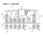
- FIG. 4 is a schematic diagram illustrating a newspaper offset rotary printing press according to the first embodiment.
- FIG. 5 is a schematic diagram illustrating a printing blanket according to the second embodiment of the present invention.
- FIG. 6 is a schematic diagram illustrating a printing blanket according to a third embodiment of the present invention.
- FIG. 7 is a schematic side view illustrating a blanket cylinder according to the fourth embodiment of the present invention.
- FIG. 8 is a schematic side view illustrating a blanket cylinder according to the fifth embodiment of the present invention.
- FIG. 9 is a schematic side view illustrating a blanket cylinder according to the sixth embodiment of the present invention.
- FIG. 1 is a schematic diagram illustrating a blanket cylinder and a plate cylinder according to a first embodiment of the present invention
- FIG. 2 is a schematic diagram illustrating a printing blanket according to the first embodiment
- FIG. 3 illustrates a blanket cylinder according to the first embodiment
- FIG. 4 is a schematic diagram illustrating a newspaper offset rotary printing press according to the first embodiment.
- the newspaper offset rotary printing press applied as a printing press includes a paper feeding device 11, a printing device 12, a turn bar device 13, and a folding machine 14. Yes.
- the paper feeding device 11 is provided with a plurality of holding arms 15 for holding three webs R each of which a web (paper) W is wound in a roll shape, and by rotating each holding arm 15, The web R can be rotated to the paper feed position.
- the paper feeding device 11 is provided with a paper splicing device (not shown), and when the web R fed out at the paper feeding position becomes small, the paper splicing device causes the paper web R at the paper feeding position to be removed.
- the web R in the standby position can be spliced.
- the printing apparatus 12 is provided with a multicolor printing unit 16 that performs double-sided four-color printing and a two-color printing unit 17 that performs double-sided two-color printing.
- the multi-color printing unit 16 and the two-color printing unit 17 can perform predetermined printing on the web W supplied from the paper feeding device 11.
- the printing apparatus 12 includes the multi-color printing unit 16 and the two-color printing unit 17, but the present invention is not limited to this configuration.
- various units may be used in combination as appropriate according to the printed matter, such as a double-sided single-color printing unit that performs single-sided printing on both sides and a multi-color printing unit that performs 4-color or 2-color printing on one side.
- the turn bar device 13 is provided with a plurality of turn bars (not shown), and the travel route of each web W sent from each printing unit 16, 17 can be changed and superposed in a predetermined order.
- the folding machine 14 vertically folds the web W conveyed from the turn bar device 13, cuts the web W by a predetermined length, further folds it horizontally to form a desired fold, and then discharges the paper.
- the printing units 16 and 17 each print four colors on the web W. And two-color printing.
- the plurality of webs W printed by the printing units 16 and 17 are overlapped in a predetermined order while the travel route is changed by the turn bar device 13.
- the plurality of webs W overlapped are conveyed to the folding machine 14, where they are vertically folded, then laterally cut, and further folded laterally to form a desired crease, which is then placed on the paper discharge conveyor by the impeller.
- the paper is ejected.
- the printing unit 16 is an H-type tower unit so that four-color printing is possible.
- the printing unit 16 is configured by arranging four stacks of black, black, magenta, and yellow along the vertical direction. Since each of these stacks has almost the same configuration, one stack will be taken out for explanation.
- one stack in the printing unit 16 has a left-right (front and back) symmetrical configuration with respect to the web W traveling upward. That is, a pair of blanket cylinders 21 and 31 are arranged so as to be able to contact each other so as to contact the front and back surfaces of the web W, and the plate cylinders 22 and 32 are in contact with each blanket cylinder 21 and 31. Has been placed.
- One plate cylinder 22 is provided with two ink form rollers 23a and 23b in contact with each other, and each ink form roller 23a and 23b is an ink source roller via an ink roller group 24 composed of a number of ink rollers.
- An ink fountain 26 is disposed with respect to the ink base roller 25.
- ink application rollers 33a and 33b are disposed in contact with each other on the other plate cylinder 32, and each of the ink application rollers 33a and 33b passes through an ink roller group 34 including a plurality of ink rollers.
- An ink fountain 36 is disposed with respect to the ink base roller 35.
- the water-based ink whose supply amount is adjusted by the ink source rollers 25 and 35 is supplied from the ink fountains 26 and 36, and is supplied to the ink forming rollers 23a, 23b, 33a and 33b via the ink roller groups 24 and 34.
- the ink application rollers 23a, 23b, 33a and 33b are supplied to the plate surfaces of the plate cylinders 22 and 32, and the ink adhering to the plate surfaces is transferred to the blanket cylinders 21 and 31.
- a predetermined printing pressure is applied to the web W between the blanket cylinder 21 that performs the front surface printing and the blanket cylinder 31 that performs the back surface printing, so that the surface of the web W and the ink of the blanket cylinders 21 and 31 are used as patterns. Can be transferred to the back side.
- the blanket cylinders 21 and 31 and the plate cylinders 22 and 32 in the printing unit 16 configured as described above will be described. Since the printing unit 16 has a bilaterally symmetric structure, one blanket cylinder 21 and the plate cylinder 22 are provided. Will be described.
- the plate cylinder 22 is configured by mounting a printing plate 42 on the outer periphery of a plate cylinder main body 41.
- the plate cylinder main body 41 has a cylindrical shape, and a notch 43 is formed along the axial direction at a predetermined position in the circumferential direction of the outer peripheral portion.
- the plate clamping device 44 is accommodated in the notch 43.
- the plate fastening device 44 fastens fastening portions 42a and 42b formed by bending each end portion in the longitudinal direction of the printing plate 42.
- the plate 42 is wound around the plate cylinder body 41 in a state where the fastening portion 42a on the grip side of the printing plate 42 is locked to the notch 43, and is pulled while holding the fastening portion 42b on the bottom side. While fixing.
- the blanket cylinder 21 is configured by mounting a blanket (printing blanket) 52 on the outer periphery of the blanket cylinder body 51.
- the blanket cylinder body 51 has a columnar shape, and a notch 53 is formed along the axial direction at a predetermined position in the circumferential direction of the outer periphery, and the blanket fastening device 54 is accommodated in the notch 53.
- the blanket fastening device 54 fastens fastening portions 52a and 52b formed by bending respective end portions of the blanket 52 in the longitudinal direction. Specifically, the blanket 52 is wound around the blanket body 51 with the gripping-side fastening portion 52a of the blanket 52 locked to the notch 53, and the bottom-side fastening portion 52b is held and fixed while being pulled. To do.
- the blanket cylinder 21 has a blanket 52 mounted on the outer periphery of a blanket cylinder body (rotating body) 51, and is rotated synchronously with the plate cylinder 22, thereby transferring an ink image transferred from the printing plate 42 of the plate cylinder 22. Can be transferred to the web W.
- the blanket cylinder 21 has a circumference (diameter) set to an integral multiple of the circumference (diameter) of the plate cylinder 22 (in this embodiment, twice). Then, when the blanket cylinder 21 and the plate cylinder 22 rotate synchronously, the rotation phase is set so that the notches 43 and 53 always coincide.
- the blanket cylinder 21 has an axial direction corresponding to the fastening position of the printing plate 42 in the plate cylinder 22, that is, the notch 43, on the surface of the blanket 52 attached to the outer peripheral portion.
- a recess 55 is provided.
- ink scum tends to accumulate at the corners of the outer peripheral surface of the plate cylinder 22 and the notch 43.
- the blanket cylinder 21 is also transferred to the web W up to the ink residue, and the outer periphery of the web W (the frame of the newspaper) Part).
- the circumferential length of the blanket cylinder 21 is set to be twice the circumferential length of the plate cylinder 22, when the blanket cylinder 21 rotates once, the plate cylinder 22 rotates twice.
- the notch 43 comes to the position facing the outer peripheral surface of the blanket cylinder 21 twice.
- the ink collected in the vicinity of the notch 43 of the plate cylinder 22 is provided on the outer periphery of the blanket cylinder 21 by providing a plurality of concave portions at equal intervals corresponding to the notch 43 of the plate cylinder 22. The dust is prevented from being transferred to the blanket cylinder 21.
- the notch portion 53 is also used as one concave portion, and the above-described concave portion 55 is provided at a position facing the notch portion 53 in the circumferential direction by 180 degrees. Accordingly, the plate cylinder 22 and the blanket cylinder 21 rotate synchronously, and when the blanket cylinder 21 rotates once, the plate cylinder 22 rotates twice. At this time, the notch portion 53 and the notch portion 43 of the plate cylinder 22 Since the concave portions 55 are alternately opposed to each other, the ink residue accumulated in the vicinity of the notch 43 of the plate cylinder 22 is prevented from being transferred to the blanket cylinder 21.
- the circumferential lengths of the notch 53 and the recess 55 in the blanket cylinder 21 need to be set longer than the circumferential length of the notch 43 in the plate cylinder 22. That is, when the notch 43 of the plate cylinder 22 comes to a position facing the notch 53 and the recess 55 of the blanket cylinder 21, the corner between the outer peripheral surface of the plate cylinder 22 and the notch 43 is notched in the blanket cylinder 21. By being located inside the portion 53 and the recessed portion 55, the corner portion does not contact the outer peripheral surface of the blanket cylinder 21, and the transfer of ink scum from the plate cylinder 22 to the blanket cylinder 21 is prevented.
- the nip width A between the blanket cylinder 21 and the plate cylinder 22, the circumferential length L1 of the notch 53 and the recess 55 in the blanket cylinder 21, and the circumferential length L2 of the notch 43 in the plate cylinder 22 is desirable to have a relationship of A> L1> L2.
- the blanket 52 of the blanket cylinder 21 will be described in detail.
- the blanket 52 is located at a predetermined position on the surface, in the present embodiment, at an intermediate portion in the longitudinal direction (winding direction around the blanket cylinder body 51-circumferential direction), and in the axial direction of the blanket cylinder body 51.
- a concave portion 55 is provided.
- the blanket 52 includes a base portion 56 that can be fastened to the blanket cylinder body 51, and a plurality (two in this embodiment) of elastic layers 57a provided on the surface of the base portion 56 at predetermined intervals in the longitudinal direction. , 57b, and a recess 55 is provided between the two elastic layers 57a, 57b.
- the base portion 56 is a plate material made of metal (for example, steel, aluminum, etc.), and the above-described fastening portions 52a and 52b are formed by bending an end portion in the longitudinal direction.
- FRP fiber reinforced plastic
- the elastic layers 57a and 57b are generally used blanket materials, and are composed of a base fabric layer, a foamed layer (compressed layer), and a rubber layer stacked in one layer or multiple layers. Placed in.
- two elastic layers 57a and 57b having the same length are attached to the surface of the base 56 with an adhesive at a predetermined interval in the longitudinal direction, and the base 56 and end portions of the elastic layers 57a and 57b
- the sealing material 58 By sticking the sealing material 58 between the two layers, a recess 55 along the width direction is formed between the elastic layers 57a and 57b, and the blanket 52 is manufactured.
- the sealing material 58 prevents the elastic layers 57a and 57b from peeling off from the base portion 56.
- the fastening portions 52a and 52b may be formed in advance with respect to the base portion 56, or may be formed last.
- the other blanket cylinder 31 and the plate cylinder 32 have the same configuration. The same applies to the other stacks in the printing unit 16, and the same applies to the other printing units 16 and 17.
- a printing unit is configured with a transferable blanket cylinder 21, the circumferential length of the blanket cylinder 21 is set to twice the circumferential length of the plate cylinder 22, and the blanket 52 has a surface corresponding to the notch 43 in the plate cylinder 22.
- the notches 53 and the recesses 55 along the axial direction are provided at equal intervals.
- the notch 43 in the plate cylinder 22 faces the notch 53 and the recess 55 of the blanket cylinder 21 so that the ink scum from the plate cylinder 22 to the blanket cylinder 21 is removed. It is possible to improve the print quality by suppressing the transfer.
- each end portion in the longitudinal direction of the blanket 52 having a sheet shape is fastened to the outer peripheral portion of the blanket cylinder main body 51, and the notch portion 53 corresponds to the notch portion 43 of the plate cylinder 22.
- the recessed part 55 is provided and a structure can be simplified by utilizing the notch part 53 which accommodates the blanket fastening apparatus 54 as a recessed part.
- the circumferential lengths of the notch 53 and the recess 55 are set longer than the circumferential length of the notch 43 of the plate cylinder 22, and the notch 43 of the plate cylinder 22 is set. Does not come into contact with the outer peripheral surface of the blanket cylinder 21, and the transfer of the ink scum from the plate cylinder 22 to the blanket cylinder 21 can be suppressed.
- a fastening portion 52a, 52b that can be fastened to the blanket cylinder 21 is provided at each end in the longitudinal direction in a sheet shape, and a recess 55 is provided at an intermediate position in the longitudinal direction.
- the recess 55 can be easily formed.
- the two elastic layers 57a and 57b are provided at predetermined intervals in the longitudinal direction on the surface of the base portion 56 that can be fastened to the blanket cylinder 21, and the concave portion along the width direction therebetween. 55 is formed to manufacture the blanket 52. Therefore, it is not necessary to process the elastic layers 57a and 57b, and the recess 55 can be easily formed.
- FIG. 5 is a schematic view showing a printing blanket according to Embodiment 2 of the present invention.
- the configuration of the blanket cylinder and the plate cylinder on which the printing blanket of this embodiment is mounted is substantially the same as that of the first embodiment described above, and will be described with reference to FIG. Members having similar functions are denoted by the same reference numerals, and redundant description is omitted.
- the plate cylinder 22 is configured by mounting a printing plate 42 on the outer peripheral portion of the plate cylinder main body 41, and a notch 43 along the axial direction is formed on the outer peripheral portion.
- the plate clamping device 44 is accommodated in the notch 43.
- the blanket cylinder 21 is configured by mounting a blanket (printing blanket) 61 on the outer periphery of the blanket cylinder main body 51, and a notch 53 is formed in the outer periphery along the axial direction.
- a fastening device 54 is accommodated.
- the blanket cylinder 21 has a circumference set to twice the circumference of the plate cylinder 22 so that when the blanket cylinder 21 and the plate cylinder 22 rotate synchronously, the notches 43 and 53 always coincide.
- the rotation phase is set.
- a concave portion 64 along the axial direction is provided on the surface of the blanket 61 attached to the outer peripheral portion, corresponding to the fastening position of the printing plate 42 in the plate cylinder 22, that is, the notch 43. ing.
- the circumference of the blanket cylinder 21 is set to be twice the circumference of the plate cylinder 22, when the blanket cylinder 21 makes one revolution, the plate cylinder 22 makes two revolutions.
- the notch 43 comes to the position facing the outer peripheral surface of the blanket cylinder 21 twice.
- the ink collected in the vicinity of the notch 43 of the plate cylinder 22 is provided on the outer periphery of the blanket cylinder 21 by providing a plurality of concave portions at equal intervals corresponding to the notch 43 of the plate cylinder 22.
- the dust is prevented from being transferred to the blanket cylinder 21.
- the blanket cylinder 21 is provided with a recess 64 at a position facing the notch 53 in the circumferential direction by 180 degrees.
- the notch portions 53 and the recesses 64 alternately face the notch portions 43 of the plate cylinder 22, thereby causing the plate cylinder.
- the ink residue collected in the vicinity of the notch 43 of the 22 is prevented from being transferred to the blanket cylinder 21.
- the blanket 61 of the blanket cylinder 21 will be described in detail.
- the blanket 61 is located at a predetermined position on the surface, in the present embodiment, in an intermediate portion in the longitudinal direction (winding direction around the blanket cylinder body 51-circumferential direction), and in the axial direction of the blanket cylinder body 51.
- a concave portion 64 is provided.
- the blanket 61 has a base portion 62 that can be fastened to the blanket cylinder body 51 and one elastic layer 63 provided on the surface of the base portion 62, and an intermediate portion in the longitudinal direction of the elastic layer 63.
- a recess 64 is provided on the surface.
- Fastening portions 62 a and 62 b to the blanket cylinder main body 51 are formed at the end portion of the base portion 62 in the longitudinal direction.
- the elastic layer 63 is attached to the surface of the base 62 with an adhesive, and a predetermined position in the longitudinal direction in the elastic layer 63, in this embodiment, an intermediate position in the longitudinal direction is set to a desired thickness along the width direction.
- the recess 64 is formed by partially cutting away a predetermined thickness while leaving the mark.
- the blanket 61 is manufactured by affixing the sealing material 65 between the base 62 and the edge part of the elastic layer 63.
- the circumference of the blanket cylinder 21 is set to be twice the circumference of the plate cylinder 22, and the surface of the blanket 61 is axially corresponding to the notch 43 in the plate cylinder 22.
- the notch part 53 and the recessed part 64 which are along are provided at equal intervals. Accordingly, when the plate cylinder 22 and the blanket cylinder 21 rotate, the notch 43 in the plate cylinder 22 faces the notch 53 and the recess 64 of the blanket cylinder 21 so that the ink scum from the plate cylinder 22 to the blanket cylinder 21 is removed. It is possible to improve the print quality by suppressing the transfer.
- a base 62 that can be fastened to the blanket cylinder body 51, an elastic layer 63 is provided on the surface of the base 62, and a recess 64 is provided on the surface of the elastic layer 63. Therefore, a predetermined rigidity can be ensured by the base 62, and ink transferability can be ensured by the elastic layer 63. Also, by providing the recess 64 on the surface of the elastic layer 63, the position of the recess 64 can be secured. Can be formed with high accuracy. Furthermore, since the elastic layer 63 is configured by a single member, peeling from the base 62 can be suppressed.
- the elastic layer 63 is provided on the surface of the base 62 that can be fastened to the blanket cylinder body 51, and a predetermined position in the longitudinal direction of the elastic layer 63 is cut in the width direction.
- the recess 64 is formed and manufactured. Therefore, the position of the recess can be formed with high accuracy.
- FIG. 6 is a schematic view showing a printing blanket according to Embodiment 3 of the present invention.
- the configuration of the blanket cylinder and the plate cylinder on which the printing blanket of this embodiment is mounted is substantially the same as that of the first embodiment described above, and will be described with reference to FIG. Members having similar functions are denoted by the same reference numerals, and redundant description is omitted.
- the plate cylinder 22 is configured by mounting a printing plate 42 on the outer peripheral portion of the plate cylinder main body 41, and a notch 43 along the axial direction is formed on the outer peripheral portion.
- the plate clamping device 44 is accommodated in the notch 43.
- the blanket cylinder 21 is configured by mounting a blanket (printing blanket) 71 on the outer peripheral portion of the blanket cylinder main body 51, and a notch 53 along the axial direction is formed on the outer periphery.
- a fastening device 54 is accommodated.
- the blanket cylinder 21 has a circumference set to twice the circumference of the plate cylinder 22 so that when the blanket cylinder 21 and the plate cylinder 22 rotate synchronously, the notches 43 and 53 always coincide.
- the rotation phase is set.
- a concave portion 74 along the axial direction is provided on the surface of the blanket 71 attached to the outer peripheral portion, corresponding to the fastening position of the printing plate 42 in the plate cylinder 22, that is, the notch 43. ing.
- the circumference of the blanket cylinder 21 is set to be twice the circumference of the plate cylinder 22, when the blanket cylinder 21 makes one revolution, the plate cylinder 22 makes two revolutions.
- the notch 43 comes to the position facing the outer peripheral surface of the blanket cylinder 21 twice.
- the ink collected in the vicinity of the notch 43 of the plate cylinder 22 is provided on the outer periphery of the blanket cylinder 21 by providing a plurality of concave portions at equal intervals corresponding to the notch 43 of the plate cylinder 22.
- the dust is prevented from being transferred to the blanket cylinder 21.
- the blanket cylinder 21 is provided with a recess 74 at a position facing the notch 53 in the circumferential direction by 180 degrees.
- the notch portions 53 and the recesses 74 alternately face the notch portions 43 of the plate cylinder 22.
- the ink residue collected in the vicinity of the notch 43 of the 22 is prevented from being transferred to the blanket cylinder 21.
- the blanket 71 of the blanket cylinder 21 will be described in detail.
- the blanket 71 is located at a predetermined position on the surface, in the present embodiment, in an intermediate portion in the longitudinal direction (winding direction around the blanket cylinder body 51-circumferential direction), and in the axial direction of the blanket cylinder body 51.
- a concave portion 74 is provided.
- the blanket 71 has a base portion 72 that can be fastened to the blanket cylinder body 51, and one elastic layer 73 provided on the surface of the base portion 72 at a predetermined interval in the longitudinal direction.
- a recess 74 is provided on the surface of the intermediate portion in the longitudinal direction. That is, fastening portions 72a and 72b to the blanket cylinder body 51 are formed at the end portion in the longitudinal direction of the base portion 72, and a concave portion 72c is formed on the surface of the intermediate position in the longitudinal direction, so that a predetermined length is obtained.
- the thin-walled portion 72d is formed.
- the elastic layer 73 is affixed on the surface of the base 72 with an adhesive agent, so that the elastic layer 73 is deformed so as to enter the recess 72c by the thin portion 72d, and the recess 74 is formed. Then, the blanket 71 is manufactured by sticking the sealing material 75 between the base 72 and the end of the elastic layer 73.
- the circumferential length of the blanket cylinder 21 is set to be twice the circumferential length of the plate cylinder 22, and the surface of the blanket 71 is axially corresponding to the notch 43 in the plate cylinder 22.
- the notch part 53 and the recessed part 74 which are along are provided at equal intervals. Accordingly, when the plate cylinder 22 and the blanket cylinder 21 rotate, the notch 43 in the plate cylinder 22 and the notch 53 and the recess 74 of the blanket cylinder 21 face each other, so that the ink scum from the plate cylinder 22 to the blanket cylinder 21 is removed. It is possible to improve the print quality by suppressing the transfer.
- a base 72 that can be fastened to the blanket cylinder main body 51 an elastic layer 73 is provided on the surface of the base 72, a thin portion 72d is provided at a predetermined position in the base 72, and a thin portion 72d is provided.
- the elastic layer 73 is deformed to form the recess 74. Therefore, by forming the concave portion 74 in the elastic layer 73 by the thin-walled portion 72d of the base portion 72, the concave portion 74 can be easily formed without changing the shape of the elastic layer 73, and the durability of the elastic layer 73 is improved. can do.
- FIG. 7 is a schematic side view showing a blanket cylinder according to Example 4 of the present invention.
- the blanket cylinder 81 has a blanket (for printing) on the outer peripheral portion of the blanket cylinder main body 82 via a plurality (two in this embodiment) of films (sheets) 83a and 83b.
- a blanket) 84 is mounted, and a cutout portion 82a along the axial direction is formed in the outer peripheral portion.
- a blanket fastening device (not shown) is accommodated in the cutout portion 82a.
- the films 83a and 83b are preferably made of a metal material, a plastic material, nylon (polyamide synthetic fiber), fiber, or the like.
- the blanket cylinder 81 has a circumference set to twice the circumference of a plate cylinder (not shown).
- a plate cylinder not shown.
- the notch 82a of the blanket cylinder 81 and the notch of the plate cylinder The rotation phase is set so that the parts always coincide.
- a concave portion 85 is provided on the surface of the blanket 84 attached to the outer peripheral portion, corresponding to the fastening position of the printing plate in the plate cylinder, that is, the notch, along the axial direction.
- the circumference of the blanket cylinder 81 is set to be twice the circumference of the plate cylinder, when the blanket cylinder 81 makes one revolution, the plate cylinder makes two revolutions.
- the blanket cylinder 81 comes to the opposite position twice with respect to the outer peripheral surface.
- a plurality of concave portions are provided at equal intervals in the outer peripheral portion of the blanket cylinder 81 corresponding to the notches of the plate cylinder, so that the ink scum accumulated in the vicinity of the notches of the plate cylinder is blanket cylinder 81. So that it is not transcribed.
- the blanket cylinder 81 is provided with a recess 85 at a position facing the notch 82a by 180 degrees in the circumferential direction. Accordingly, when the plate cylinder and the blanket cylinder 81 rotate synchronously and the blanket cylinder 81 makes one rotation, the notch portions 82a and the recesses 85 alternately face the notch portions of the plate cylinder, so that the notch portions of the plate cylinder Is prevented from being transferred to the blanket cylinder 81.
- the blanket cylinder 81 will be described in detail.
- Two films 83a and 83b are attached to the outer peripheral portion of the blanket cylinder body 82 with a predetermined gap in the circumferential direction by an adhesive, and the blanket 84 is attached to the surfaces of the films 83a and 83b, and the fastening portions 84a and 84b.
- the blanket 84 is deformed toward the center side of the blanket cylinder main body 82 by the gap between the two films 83a and 83b, so that the recess 85 is formed.
- the recess 85 is provided on the surface of the intermediate portion of the blanket 84 in the longitudinal direction.
- the circumferential length of the blanket cylinder 81 is set to be twice the circumferential length of the plate cylinder, and the notch portion along the axial direction corresponding to the notch portion of the plate cylinder on the surface of the blanket 84 82a and the recessed part 85 are provided at equal intervals. Therefore, when the plate cylinder and the blanket cylinder 81 rotate, the notch portion of the plate cylinder and the notch portion 82a and the recess 85 of the blanket cylinder 81 face each other, thereby suppressing the transfer of ink scum from the plate cylinder to the blanket cylinder 81. Printing quality can be improved.
- the films 83a and 83b are attached to the outer peripheral portion of the blanket cylinder body 82 with a predetermined gap in the circumferential direction, and the blanket 84 is attached to the surfaces of the films 83a and 83b.
- the blanket 84 is deformed by the gap 83b to form the recess 85. Therefore, by forming the recess 85 in the blanket 84 by the gap between the films 83a and 83b, the recess 85 can be easily formed without changing the shape of the blanket 84, and the durability of the blanket 84 can be improved. it can.
- FIG. 8 is a schematic side view showing a blanket cylinder according to the fifth embodiment of the present invention.
- the blanket cylinder 91 is configured by mounting a blanket (printing blanket) 93 on the outer peripheral portion of the blanket cylinder main body 92.
- the blanket 93 has a cylindrical shape and functions as a fastening portion that can be fitted and fastened to the outer peripheral surface of the blanket cylinder main body 92.
- the blanket cylinder main body 92 has a main body portion and a smaller diameter portion smaller than the main body portion, and an air blowing hole is formed on the outer peripheral surface of the small diameter portion. Therefore, after inserting the blanket 93 into the small-diameter portion of the blanket cylinder main body 92, the air is blown out from the air blowing hole to increase the diameter by pressing the blanket 93 from the inside.
- the blanket 93 is inserted into the main body portion.
- the blanket 93 is reduced in diameter and fitted to the blanket cylinder main body 92 (main body portion). In this way, the blanket 93 is fastened to the outer peripheral surface of the blanket cylinder main body 92.
- the blanket cylinder 91 has a circumference set to twice the circumference of a plate cylinder (not shown), and two concave portions 96a and 96b are provided on the surface at equal intervals in the circumferential direction. Is rotated so that the notch of the plate cylinder and the recesses 96a and 96b always coincide with each other when the plate rotates synchronously.
- concave portions 96a and 96b along the axial direction are provided on the surface of the blanket 93 attached to the outer peripheral portion of the blanket cylinder 91, corresponding to the fastening position of the printing plate in the plate cylinder, that is, the notch. .
- the circumferential length of the blanket cylinder 91 is set to be twice the circumferential length of the plate cylinder, when the blanket cylinder 91 makes one rotation, the plate cylinder rotates twice.
- the blanket cylinder 91 comes to the opposite position twice with respect to the outer peripheral surface. For this reason, in this embodiment, by providing two concave portions 96a and 96b at equal intervals in the outer peripheral portion of the blanket cylinder 91 corresponding to the notch portions of the plate cylinder, ink scum accumulated in the vicinity of the notch portions of the plate cylinder.
- the blanket cylinder 91 is prevented from being transferred.
- the two concave portions 96a and 96b are provided at positions facing each other by 180 degrees in the circumferential direction. Accordingly, when the plate cylinder and the blanket cylinder 91 rotate synchronously and the blanket cylinder 91 makes one rotation, the recesses 96a and 96b alternately face the notches of the plate cylinder so that the vicinity of the notches of the plate cylinder. It is prevented that the ink residue accumulated in the ink is transferred to the blanket cylinder 91.
- the blanket 93 of the blanket cylinder 91 has a cylindrical base portion 94 that can be fastened to the blanket cylinder main body 92, and two elastic layers 95a and 95b provided on the surface of the base portion 94 at predetermined intervals in the longitudinal direction.
- the elastic layer 95a , 95b are provided with recesses 96a, 96b at both ends in the longitudinal direction.
- the circumferential length of the blanket cylinder 91 is set to be twice the circumferential length of the plate cylinder, and the surface of the blanket 93 corresponds to the notch portion in the plate cylinder and is a recess 96a along the axial direction. 96b are provided at equal intervals. Therefore, when the plate cylinder and the blanket cylinder 91 rotate, the notches in the plate cylinder and the recesses 96a and 96b of the blanket cylinder 91 face each other, thereby suppressing the transfer of ink scum from the plate cylinder to the blanket cylinder 91 for printing. The quality can be improved.
- a blanket 93 having a cylindrical shape is fitted and fastened to the outer peripheral portion of the blanket cylinder main body 92, and two concave portions 96 a and 96 b are provided on the surface of the blanket 93. Accordingly, the recesses 96a and 96b can be easily formed in the blanket cylinder 91.
- FIG. 9 is a schematic side view showing a blanket cylinder according to Example 6 of the present invention.
- the blanket cylinder 101 is configured by mounting a plurality of (two in this embodiment) blankets (printing blankets) 103a and 103b on the outer peripheral portion of the blanket cylinder main body 102.
- a plurality of blankets (printing blankets) 103a and 103b has been.
- two notches 102a and 102b are formed along the circumferential direction at equal intervals along the circumferential direction on the outer periphery, and blanket fastening devices 102c and 102b are formed on the notches 102a and 102b, respectively. 102d is accommodated.
- each edge part of each blanket 103a, 103b is fastened by corresponding blanket fastening apparatus 102c, 102d, and blanket 103a, 103b is mounted
- the circumference of the blanket cylinder 101 is set to twice the circumference of a plate cylinder (not shown), and when the blanket cylinder 101 and the plate cylinder rotate synchronously, the notch portion of the plate cylinder and the blanket cylinder 101 The rotation phase is set so that the notches 102a and 102b always coincide.
- the circumference of the blanket cylinder 101 is set to be twice the circumference of the plate cylinder, when the blanket cylinder 101 makes one revolution, the plate cylinder makes two revolutions. Then, the blanket cylinder 101 comes to the opposite position twice with respect to the outer peripheral surface. Therefore, in this embodiment, the ink collected in the vicinity of the notch portion of the plate cylinder is provided on the outer peripheral portion of the blanket cylinder 101 by providing two notch portions 102a and 102b at equal intervals corresponding to the notch portion of the plate cylinder. The dust is prevented from being transferred to the blanket cylinder 101.
- the circumferential length of the blanket cylinder 101 is set to be twice the circumferential length of the plate cylinder, and the notches 102a and 102b along the two axial directions correspond to the notches in the plate cylinder.
- the blanket fastening devices 102c and 102d for fastening the ends of the blankets 103a and 103b to the notches 102a and 102b are accommodated. Therefore, when the plate cylinder and the blanket cylinder 101 rotate, the notch portions of the plate cylinder and the notches 102a and 102b of the blanket cylinder 101 face each other, thereby suppressing transfer of ink scum from the plate cylinder to the blanket cylinder 101. The print quality can be improved.
- the length can be set to an integral multiple of the circumference of the plate cylinder, and may be three times, four times, or the like.
- the number of recesses may be set according to the circumferential length of the blanket cylinder, and a plurality of recesses may be provided at equal intervals in the circumferential direction.
- the printing press of the present invention has been described as applied to a newspaper offset rotary printing press, it can also be applied to a commercial offset rotary printing press.
- the printing blanket and the manufacturing method thereof, the blanket cylinder, and the printing machine according to the present invention suppress the transfer of the ink scum from the plate cylinder to the blanket cylinder by providing a recess at a predetermined position on the surface of the printing blanket. This is intended to improve the printing quality and can be applied to any printing machine.
Landscapes
- Engineering & Computer Science (AREA)
- Mechanical Engineering (AREA)
- Printing Plates And Materials Therefor (AREA)
Abstract
印刷用ブランケット及びその製造方法、ブランケット胴並びに印刷機において、刷版(42)が装着される版胴(22)と、ブランケット(52)が装着されて版胴(22)に同期回転して版胴(22)から転写されるインキ画像をウェブ(Wに)転写可能なブランケット胴(21)とを備えて印刷ユニットを構成し、ブランケット胴(21)の周長を版胴(22)の周長の2倍に設定し、ブランケット(52)の表面に版胴(22)における切欠部(43)に対応して軸方向に沿う切欠部(53)及び凹部(55)を均等間隔で設ける。
Description
本発明は、印刷機にて、ブランケット胴の外周部に装着されてインキ画像を印刷媒体に転写可能な印刷用ブランケット、この印刷用ブランケットの製造方法、この印刷用ブランケットが装着されたブランケット胴、このブランケット胴が適用された印刷機に関するものである。
例えば、一般的な新聞用オフセット輪転印刷機は、複数の給紙部と、複数の印刷ユニットと、ターンバー装置と、折機とから構成されており、各給紙部から印刷ユニットにウェブが供給されると、各ウェブに対して印刷が施され、ターンバー装置で多数のウェブの走行ルートが変更されてから所定の順番に重ね合わされた後、折機にて、ウェブが縦折りされてから所定の長さで横裁断され、横折されることで折帖が形成され、排紙される。
そして、この新聞用オフセット輪転印刷機における印刷ユニットは、4色印刷が可能であるように、H型のタワーユニットとなっており、墨、藍、紅、黄ごとの4つのスタックA,B,C,Dが上下に配置されて構成されている。各スタックは、ほぼ同様の構成をなしており、上方に向かって走行するウェブに対して左右対称をなし、ブランケット胴、版胴、インキ着ローラ、複数のインキローラ群、インキ装置が直列に設けられて構成されている。
このような印刷ユニットにて、通常、ブランケット胴と版胴は2倍胴であり、両者は、径及び周長が同一のものとなっている。ところが、版胴を2倍胴とすると、2つの刷版が必要であることから、低コスト化を図るためにブランケット胴を2倍胴とし、版胴は1倍胴としたものが提案されている。
このような従来の印刷ユニットとしては、例えば、下記特許文献1に記載されたものがある。
ところで、版胴は、外周部にシート形状をなす刷版が装着されており、この刷版は、長手方向の各端部が版胴の切欠部に収容された版締め装置に拘束されている。一方、ブランケット胴は、外周部にシート形状をなすブランケットが装着されており、このブランケットは、長手方向の各端部がブランケット胴の切欠部に収容されたブランケット締め装置に拘束されている。
この場合、ブランケット胴と版胴が2倍胴であれば、各胴の周長が同じであることから、各胴の回転時に、切欠部同士が常時一致するように回転位相が調整される。そのため、版胴の切欠部に溜まったインキかすがブランケット胴に転写することが防止される。ところが、ブランケット胴が2倍胴で、版胴が1倍胴になると、各胴の周長が異なることから、ブランケット胴が1回転するときに版胴が2回転する。そのため、各胴の切欠部同士を常時一致させることができず、版胴の切欠部に溜まったインキかすがブランケット胴に転写してしまう。その結果、ブランケット胴に転写したインキかすがウェブに転写されてしまい、ウェブの外周部に汚れが発生してしまうという問題がある。
本発明は上述した課題を解決するものであり、版胴からブランケット胴へのインキかすの転写を抑制して印刷品質の向上を図る印刷用ブランケット及びその製造方法、ブランケット胴並びに印刷機を提供することを目的とする。
上記の目的を達成するための本発明の印刷用ブランケットは、回転体の外周部に装着されてインキ画像を印刷媒体に転写可能な印刷用ブランケットにおいて、表面における所定の位置に、前記回転体の軸方向に沿う凹部が設けられることを特徴とするものである。
本発明の印刷用ブランケットでは、シート形状をなして長手方向における各端部に前記回転体に締結可能な締結部を有し、長手方向における中間位置、または、長手方向における均等間隔位置に前記凹部が設けられることを特徴としている。
本発明の印刷用ブランケットでは、円筒形状をなして前記回転体に嵌合して締結可能な締結部を有し、表面に前記凹部が周方向に均等間隔で複数設けられることを特徴としている。
本発明の印刷用ブランケットでは、前記回転体に締結可能な基部と、該基部の表面に設けられる弾性層とを有し、該弾性層の表面に前記凹部が設けられることを特徴としている。
本発明の印刷用ブランケットでは、前記回転体に締結可能な基部と、該基部の表面に長手方向に所定間隔で設けられる複数の弾性層とを有し、該複数の弾性層の間に前記凹部が設けられることを特徴としている。
本発明の印刷用ブランケットでは、前記回転体に締結可能な基部と、該基部の表面に設けられる弾性層とを有し、前記基部における所定の位置に薄肉部が設けられ、該薄肉部により前記弾性層が変形して前記凹部が形成されることを特徴としている。
また、本発明の印刷用ブランケットの製造方法は、回転体の外周部に装着されてインキ画像を印刷媒体に転写可能な印刷用ブランケットにおいて、前記回転体に締結可能な基部の表面に弾性層を設け、該弾性層における長手方向の所定の位置を幅方向に切除することで、凹部を形成して前記印刷用ブランケットを製造することを特徴とするものである。
本発明の印刷用ブランケットの製造方法は、回転体の外周部に装着されてインキ画像を印刷媒体に転写可能な印刷用ブランケットにおいて、前記回転体に締結可能な基部の表面に弾性層を長手方向に所定間隔で設けることで、幅方向に沿う凹部を形成して前記印刷用ブランケットを製造することを特徴とするものである。
また、本発明のブランケット胴は、版胴に同期回転して該版胴から転写されるインキ画像を印刷媒体に転写可能であり、周長が前記版胴の周長の整数倍に設定されるブランケット胴において、表面に、前記版胴における刷版の締結位置に対応して、軸方向に沿う凹部が均等間隔で複数設けられることを特徴とするものである。
本発明のブランケット胴では、ブランケット胴本体の外周部に、シート形状をなすブランケットの長手方向における各端部が締結され、前記複数の凹部のうちの少なくとも一つの凹部は、前記ブランケットの各端部を前記胴本体に締結する締結機構が収容されるものであり、残りの凹部は、前記ブランケットの表面に設けられるものであることを特徴としている。
本発明のブランケット胴では、ブランケット胴本体の外周部に、円筒形状をなすブランケットが嵌合して締結され、前記複数の凹部は、前記ブランケットの表面に設けられるものであることを特徴としている。
本発明のブランケット胴では、ブランケット胴本体の外周部に、周方向に所定隙間をもってシートが複数装着され、該複数のシートの表面にブランケットが装着され、前記複数のシートの隙間により前記ブランケットが変形して前記凹部が形成されることを特徴としている。
本発明のブランケット胴では、前記凹部における周方向の長さは、前記版胴における刷版の締結部に形成された切欠部の周方向の長さより長く設定されることを特徴としている。
また、本発明の印刷機は、刷版が装着される版胴と、ブランケットが装着されて前記版胴に同期回転して該版胴から転写されるインキ画像を印刷媒体に転写可能なブランケット胴と、を備える印刷機において、前記ブランケット胴の周長が前記版胴の周長の整数倍に設定され、前記ブランケットの表面に、前記版胴における前記刷版の締結位置に対応して、軸方向に沿う凹部が均等間隔で複数設けられることを特徴とするものである。
本発明の印刷用ブランケットによれば、回転体の外周部に装着されてインキ画像を印刷媒体に転写可能に構成し、表面における所定の位置に回転体の軸方向に沿う凹部を設けている。従って、版胴からブランケット胴へのインキかすの転写を抑制して印刷品質の向上を図ることができる。
本発明の印刷用ブランケットによれば、シート形状をなして長手方向における各端部に回転体に締結可能な締結部を設け、長手方向における中間位置、または、長手方向における均等間隔位置に凹部が設けるので、凹部を容易に形成することができる。
本発明の印刷用ブランケットによれば、円筒形状をなして回転体に嵌合して締結可能な締結部を設け、表面に凹部を周方向に均等間隔で複数設けるので、凹部を容易に形成することができる。
本発明の印刷用ブランケットによれば、回転体に締結可能な基部と、基部の表面に弾性層を設け、弾性層の表面に凹部を設けるので、基部により所定の剛性を確保することができ、弾性層によりインキの転写性を確保することができ、また、この弾性層の表面に凹部を設けることで、凹部の位置を精度良く形成することができる。
本発明の印刷用ブランケットによれば、回転体に締結可能な基部と、基部の表面に長手方向に所定間隔で複数の弾性層を設け、複数の弾性層の間に凹部を設けるので、基部により所定の剛性を確保することができ、弾性層によりインキの転写性を確保することができ、また、この弾性層の間に凹部を設けることで、凹部を容易に形成することができる。
本発明の印刷用ブランケットによれば、回転体に締結可能な基部と、基部の表面に弾性層を設け、基部における所定の位置に薄肉部を設け、薄肉部により弾性層を変形して凹部を形成するので、基部の薄肉部により弾性層に凹部を形成することで、弾性層の形状を変更することなく凹部を形成することができ、弾性層の耐久性を向上することができる。
また、本発明の印刷用ブランケットの製造方法によれば、回転体の外周部に装着されてインキ画像を印刷媒体に転写可能な印刷用ブランケットを、回転体に締結可能な基部の表面に弾性層を設け、弾性層における長手方向の所定の位置を幅方向に切除することで、凹部を形成して製造する。従って、凹部の位置を精度良く形成することができる。
本発明の印刷用ブランケットの製造方法によれば、回転体の外周部に装着されてインキ画像を印刷媒体に転写可能な印刷用ブランケットを、回転体に締結可能な基部の表面に弾性層を長手方向に所定間隔で設けることで、幅方向に沿う凹部を形成して製造する。従って、凹部を容易に形成することができる。
また、本発明のブランケット胴によれば、版胴に同期回転して版胴から転写されるインキ画像を印刷媒体に転写可能とすると共に、周長を版胴の周長の整数倍に設定して構成し、表面に、版胴における刷版の締結位置に対応して、軸方向に沿う凹部を均等間隔で複数設けている。従って、版胴とブランケット胴が回転するとき、版胴における刷版の締結位置とブランケット胴の凹部が対向することで、版胴からブランケット胴へのインキかすの転写を抑制して印刷品質の向上を図ることができる。
本発明のブランケット胴によれば、ブランケット胴本体の外周部にシート形状をなすブランケットの長手方向における各端部を締結し、複数の凹部のうちの少なくとも一つの凹部をブランケットの各端部を胴本体に締結する締結機構を収容するものとし、残りの凹部をブランケットの表面に設けるものとするので、締結機構を収容する部分を凹部として利用することで、構成を簡素化することができる。
本発明のブランケット胴によれば、ブランケット胴本体の外周部に円筒形状をなすブランケットを嵌合して締結し、複数の凹部をブランケットの表面に設けるものとするので、凹部を簡単に形成することができる。
本発明のブランケット胴によれば、ブランケット胴本体の外周部に周方向に所定隙間をもってシートを複数装着し、複数のシートの表面にブランケットを装着し、複数のシートの隙間によりブランケットを変形して凹部を形成するので、シートの隙間によりブランケットに凹部を形成することで、ブランケットの形状を変更することなく凹部を形成することができ、弾性層の耐久性を向上することかできる。
本発明のブランケット胴によれば、凹部における周方向の長さを版胴における刷版の締結部に形成された切欠部の周方向の長さより長く設定するので、版胴の切欠部がブランケット胴の外周面に接触することがなく、版胴からブランケット胴へのインキかすの転写を抑制することができる。
また、本発明の印刷機によれば、刷版が装着される版胴と、ブランケットが装着されて版胴に同期回転して版胴から転写されるインキ画像を印刷媒体に転写可能なブランケット胴とを備え、ブランケット胴の周長を版胴の周長の整数倍に設定し、ブランケットの表面に版胴における刷版の締結位置に対応して軸方向に沿う凹部を均等間隔で複数設けている。従って、版胴とブランケット胴が回転するとき、版胴における刷版の締結位置とブランケット胴の凹部が対向することで、版胴からブランケット胴へのインキかすの転写を抑制して印刷品質の向上を図ることができる。
以下に添付図面を参照して、本発明に係る印刷用ブランケット及びその製造方法、ブランケット胴並びに印刷機を詳細に説明する。なお、この実施例により本発明が限定されるものではない。
図1は、本発明の実施例1に係るブランケット胴及び版胴を表す概略図、図2は、本実施例1の印刷用ブランケットを表す概略図、図3は、実施例1のブランケット胴が適用された印刷ユニットの概略図、図4は、実施例1の新聞用オフセット輪転印刷機を表す概略図である。
実施例1において、図4に示すように、印刷機として適用された新聞用オフセット輪転印刷機は、給紙装置11と、印刷装置12と、ターンバー装置13と、折機14とから構成されている。そして、給紙装置11には、それぞれウェブ(用紙)Wがロール状に巻かれた3つの巻取紙Rを保持する複数の保持アーム15が設けられ、この各保持アーム15を回動することで、巻取紙Rを給紙位置に回動することができる。また、この給紙装置11には、図示しない紙継装置が設けられており、給紙位置で繰り出されている巻取紙Rが残り少なくなると、この紙継装置により給紙位置にある巻取紙Rに対して、待機位置にある巻取紙Rを紙継することができる。
また、印刷装置12には、両面4色印刷を行う多色刷印刷ユニット16と、両面2色印刷を行う2色刷印刷ユニット17が設けられている。この多色刷印刷ユニット16及び2色刷印刷ユニット17は、給紙装置11から供給されたウェブWに対して所定の印刷を行うことができる。なお、本実施例では、印刷装置12を、多色刷印刷ユニット16と2色刷印刷ユニット17により構成したが、この構成に限定されるものではない。例えば、両面単色印刷を行う両面単色刷ユニット、一面4色または2色印刷を行う多色刷印刷ユニットなど印刷物に応じて適宜各種ユニットを組み合わせて使用すればよい。
また、ターンバー装置13には、図示しない複数のターンバーが設けられており、各印刷ユニット16,17から送り出された各ウェブWの走行ルートを変更し、所定の順番に重ね合わせることができる。折機14は、ターンバー装置13から搬送されたウェブWを縦折りし、所定の長さで横裁断し、更に横折りして所望の折帖を形成した後に排紙するものである。
従って、まず、給紙装置11から印刷装置12を構成する多色刷印刷ユニット16や2色刷印刷ユニット17にウェブWが供給されると、各印刷ユニット16,17では、各ウェブWに対して4色刷や2色刷が行われる。次に、各印刷ユニット16,17で印刷が施された複数のウェブWは、ターンバー装置13にて、走行ルートが変更されると共に、所定の順番に重ね合わせられる。そして、複数重ね合わされたウェブWは、折機14に搬送され、ここで縦折りされた後、横裁断され、更に横折りされて所望の折帖が形成され、羽根車により排紙コンベア上に排紙される。
この新聞用オフセット輪転印刷機における印刷装置12にて、印刷ユニット16は4色印刷が可能であるように、H型のタワーユニットとなっている。この印刷ユニット16は、墨(Black)、藍(Cyan)、紅(Magenta)、黄(Yellow)ごとの4つのスタックが上下方向に沿って配置されて構成されている。この各スタックは、ほぼ同様の構成をなしていることから、その一つのスタックを取り出して説明する。
印刷ユニット16における一つのスタックは、図3に示すように、上方へ向かって走行するウェブWに対して、左右(表裏)対称の構成となっている。即ち、ウェブWの表面及び裏面に接触するように、一対のブランケット胴21,31が対向して対接可能に配置されており、各ブランケット胴21,31に対接して版胴22,32が配置されている。そして、一方の版胴22には、2つのインキ着ローラ23a,23bが対接して配置され、各インキ着ローラ23a,23bは、多数のインキローラからなるインキローラ群24を介してインキ元ローラ25に対接され、このインキ元ローラ25に対してインキつぼ26が配置されている。また、他方の版胴32には、2つのインキ着ローラ33a,33bが対接して配置され、各インキ着ローラ33a,33bは、多数のインキローラからなるインキローラ群34を介してインキ元ローラ35に対接され、このインキ元ローラ35に対してインキつぼ36が配置されている。
従って、インキ元ローラ25,35により供給量が調整された水性インキが、インキつぼ26,36から供給され、インキローラ群24,34を介してインキ着ローラ23a,23b,33a,33bに供給され、このインキ着ローラ23a,23b,33a,33bから版胴22,32の版面に供給され、版面に付着したインキがブランケット胴21,31に転写される。そして、表面印刷を行うブランケット胴21と裏面印刷を行うブランケット胴31との間でウェブWに所定の印圧が掛けられることで、各ブランケット胴21,31のインキを絵柄としてウェブWの表面及び裏面に転写することができる。
ここで、このように構成された印刷ユニット16におけるブランケット胴21,31及び版胴22,32について説明するが、印刷ユニット16は左右対称構造であることから、一方のブランケット胴21及び版胴22について説明する。
図1に示すように、版胴22は、版胴本体41の外周部に刷版42が装着されて構成されている。版胴本体41は、円柱形状をなし、外周部における周方向における所定の箇所に、軸方向に沿った切欠部43が形成され、この切欠部43に版締め装置44が収容されている。この版締め装置44は、刷版42における長手方向の各端部が折り曲げられて形成された締結部42a,42bを締結するものである。具体的には、刷版42の咥え側の締結部42aが切欠部43に係止した状態で、この刷版42を版胴本体41に巻き付け、尻側の締結部42bを保持して引っ張りながら固定するものである。
ブランケット胴21は、ブランケット胴本体51の外周部にブランケット(印刷用ブランケット)52が装着されて構成されている。ブランケット胴本体51は、円柱形状をなし、外周部における周方向における所定の箇所に、軸方向に沿った切欠部53が形成され、この切欠部53にブランケット締め装置54が収容されている。このブランケット締め装置54は、ブランケット52における長手方向の各端部が折り曲げられて形成された締結部52a,52bを締結するものである。具体的には、ブランケット52の咥え側の締結部52aが切欠部53に係止した状態で、このブランケット52をブランケット胴本体51に巻き付け、尻側の締結部52bを保持して引っ張りながら固定するものである。
このブランケット胴21は、ブランケット胴本体(回転体)51の外周部にブランケット52が装着されてなり、版胴22に同期回転することで、この版胴22の刷版42から転写されるインキ画像をウェブWに転写可能である。この実施例1にて、ブランケット胴21は、周長(直径)が版胴22の周長(直径)の整数倍(本実施例では、2倍)に設定されている。そして、ブランケット胴21と版胴22とが同期回転するとき、各切欠部43,53が常時一致するように、その回転位相が設定されている。
また、実施例1では、ブランケット胴21にて、外周部に装着されるブランケット52の表面に、版胴22における刷版42の締結位置、つまり、切欠部43に対応して、軸方向に沿う凹部55が設けられている。
即ち、版胴22に対してインキが転写され、この転写されたインキをブランケット胴21に転写するとき、版胴22における外周面と切欠部43との角部にインキかすが溜まりやすい。版胴22の切欠部43の近傍に溜まったインキかすがブランケット胴21に転写されると、ブランケット胴21は、このインキかすまでもウェブWに転写してしまい、ウェブWおける外周部(新聞紙の額縁部)を汚してしまう。
この場合、ブランケット胴21の周長が版胴22の周長の2倍に設定されていることから、ブランケット胴21が1回転するとき、版胴22は2回転し、このとき、版胴22の切欠部43は、ブランケット胴21の外周面に対して2回対向位置にくる。そのため、本実施例では、ブランケット胴21の外周部に、版胴22の切欠部43に対応して均等間隔で複数の凹部を設けることで、版胴22の切欠部43の近傍に溜まったインキかすがブランケット胴21に転写されないようにしている。
ブランケット胴21の凹部は2個必要であり、切欠部53を一つの凹部として兼用し、この切欠部53と周方向に180度対向した位置に、上述した凹部55を設けている。従って、版胴22とブランケット胴21が同期回転し、ブランケット胴21が1回転するときに版胴22が2回転するが、このとき、版胴22の切欠部43に対して、切欠部53と凹部55が交互に対向することで、版胴22の切欠部43の近傍に溜まったインキかすがブランケット胴21に転写されることが防止される。
この場合、ブランケット胴21における切欠部53及び凹部55の周方向の長さは、版胴22における切欠部43の周方向の長さより長く設定する必要がある。即ち、版胴22の切欠部43が、ブランケット胴21の切欠部53及び凹部55に対向する位置にきたとき、版胴22における外周面と切欠部43との角部が、ブランケット胴21における切欠部53及び凹部55の内部に位置することで、この角部がブランケット胴21の外周面に接触せず、版胴22からブランケット胴21へのインキかすの転写が防止される。
具体的には、ブランケット胴21と版胴22のニップ幅A、ブランケット胴21における切欠部53及び凹部55の周方向の長さL1、版胴22における切欠部43の周方向の長さL2とすると、A>L1>L2の関係とすることが望ましい。
ここで、ブランケット胴21のブランケット52について詳細に説明する。ブランケット52は、図2に示すように、表面における所定の位置、本実施例では、長手方向(ブランケット胴本体51への巻き付け方向-周方向)における中間部に、ブランケット胴本体51の軸方向に沿う凹部55が設けられている。
具体的に説明すると、ブランケット52は、ブランケット胴本体51に締結可能な基部56と、この基部56の表面に長手方向に所定間隔で設けられる複数(本実施例では、2つ)の弾性層57a,57bとを有し、2つの弾性層57a,57bの間に凹部55が設けられる。この基部56は、金属(例えば、スチール、アルミなど)製の板材であって、長手方向における端部が折り曲げられることで、上述した締結部52a,52bが形成されている。なお、基部56を金属製とせずに、ガラス繊維(グラスファイバ)、このガラス繊維などプラスチックの中に入れて強度を高めた繊維強化プラスチック(FRP)などを用いてもよい。また、弾性層57a,57bは、一般的に使用されるブランケット材であり、基布層と発泡層(圧縮層)とゴム層が一層または多層に重ねられて構成され、このゴム層が表面側に配置される。
この場合、基部56の表面に同じ長さの2つの弾性層57a,57bを長手方向に対して所定の間隔をあけて接着剤により貼り付け、基部56と各弾性層57a,57bの端部との間にシール材58を貼り付けることで、各弾性層57a,57bの間に幅方向に沿う凹部55が形成され、ブランケット52が製造される。なお、シール材58により基部56からの弾性層57a,57bのはがれが防止されている。また、基部56に対して、締結部52a,52bを予め形成しておいてもよいし、最後に形成してもよい。
なお、ここでは、印刷ユニット16における一方のブランケット胴21及び版胴22についてのみ説明したが、他方のブランケット胴31及び版胴32についても同様の構成となっている。また、印刷ユニット16における他のスタックについても同様であると共に、他の印刷ユニット16,17についても同様である。
このように実施例1にあっては、刷版42が装着される版胴22と、ブランケット52が装着されて版胴22に同期回転して版胴22から転写されるインキ画像をウェブWに転写可能なブランケット胴21とを備えて印刷ユニットを構成し、ブランケット胴21の周長を版胴22の周長の2倍に設定し、ブランケット52の表面に版胴22における切欠部43に対応して軸方向に沿う切欠部53及び凹部55を均等間隔で設けている。
従って、版胴22とブランケット胴21が回転するとき、版胴22における切欠部43とブランケット胴21の切欠部53及び凹部55が対向することで、版胴22からブランケット胴21へのインキかすの転写を抑制して印刷品質の向上を図ることができる。
また、実施例1のブランケット胴21では、ブランケット胴本体51の外周部にシート形状をなすブランケット52の長手方向における各端部を締結し、版胴22の切欠部43に対応して切欠部53及び凹部55を設けており、ブランケット締め装置54を収容する切欠部53を凹部として利用することで、構成を簡素化することができる。
また、実施例1のブランケット胴21では、切欠部53及び凹部55における周方向の長さを版胴22における切欠部43の周方向の長さより長く設定しており、版胴22の切欠部43がブランケット胴21の外周面に接触することがなく、版胴22からブランケット胴21へのインキかすの転写を抑制することができる。
また、実施例1のブランケット52では、シート形状をなして長手方向における各端部にブランケット胴21に締結可能な締結部52a,52bを設け、長手方向における中間位置に凹部55を設けており、この凹部55を容易に形成することができる。
また、実施例1のブランケット52の製造方法では、ブランケット胴21に締結可能な基部56の表面に2つの弾性層57a,57bを長手方向に所定間隔で設けることで、その間に幅方向に沿う凹部55を形成してブランケット52を製造している。従って、弾性層57a,57bを加工する必要はなく、凹部55を容易に形成することができる。
図5は、本発明の実施例2に係る印刷用ブランケットを表す概略図である。なお、本実施例の印刷用ブランケットが装着されるブランケット胴及び版胴の構成は、上述した実施例1とほぼ同様であり、図1を用いて説明すると共に、この実施例で説明したものと同様の機能を有する部材には同一の符号を付して重複する説明は省略する。
実施例2において、図1及び図5に示すように、版胴22は、版胴本体41の外周部に刷版42が装着されて構成され、外周部に軸方向に沿った切欠部43が形成され、この切欠部43に版締め装置44が収容されている。一方、ブランケット胴21は、ブランケット胴本体51の外周部にブランケット(印刷用ブランケット)61が装着されて構成され、外周部に軸方向に沿った切欠部53が形成され、この切欠部53にブランケット締め装置54が収容されている。
このブランケット胴21は、周長が版胴22の周長の2倍に設定されており、ブランケット胴21と版胴22とが同期回転するとき、各切欠部43,53が常時一致するように、その回転位相が設定されている。また、ブランケット胴21にて、外周部に装着されるブランケット61の表面に、版胴22における刷版42の締結位置、つまり、切欠部43に対応して、軸方向に沿う凹部64が設けられている。
即ち、ブランケット胴21の周長が版胴22の周長の2倍に設定されていることから、ブランケット胴21が1回転するとき、版胴22は2回転し、このとき、版胴22の切欠部43は、ブランケット胴21の外周面に対して2回対向位置にくる。そのため、本実施例では、ブランケット胴21の外周部に、版胴22の切欠部43に対応して均等間隔で複数の凹部を設けることで、版胴22の切欠部43の近傍に溜まったインキかすがブランケット胴21に転写されないようにしている。具体的には、ブランケット胴21にて、切欠部53と周方向に180度対向した位置に凹部64を設けている。従って、版胴22とブランケット胴21が同期回転し、ブランケット胴21が1回転するとき、版胴22の切欠部43に対して、切欠部53と凹部64が交互に対向することで、版胴22の切欠部43の近傍に溜まったインキかすがブランケット胴21に転写されることが防止される。
ここで、ブランケット胴21のブランケット61について詳細に説明する。ブランケット61は、図5に示すように、表面における所定の位置、本実施例では、長手方向(ブランケット胴本体51への巻き付け方向-周方向)における中間部に、ブランケット胴本体51の軸方向に沿う凹部64が設けられている。
具体的に説明すると、ブランケット61は、ブランケット胴本体51に締結可能な基部62と、この基部62の表面に設けられる1つの弾性層63とを有し、この弾性層63における長手方向の中間部の表面に凹部64が設けられる。また、基部62における長手方向の端部には、ブランケット胴本体51への締結部62a,62bが形成されている。
この場合、基部62の表面に弾性層63を接着剤により貼り付け、この弾性層63における長手方向の所定の位置、本実施例では、長手方向の中間位置を幅方向に沿って所望の厚さを残して部分的に所定厚さだけ切除することで、凹部64を形成する。そして、基部62と弾性層63の端部との間にシール材65を貼り付けることで、ブランケット61が製造される。
このように実施例2にあっては、ブランケット胴21の周長を版胴22の周長の2倍に設定し、ブランケット61の表面に版胴22における切欠部43に対応して軸方向に沿う切欠部53及び凹部64を均等間隔で設けている。従って、版胴22とブランケット胴21が回転するとき、版胴22における切欠部43とブランケット胴21の切欠部53及び凹部64が対向することで、版胴22からブランケット胴21へのインキかすの転写を抑制して印刷品質の向上を図ることができる。
また、実施例2のブランケット61では、ブランケット胴本体51に締結可能な基部62と、この基部62の表面に弾性層63を設け、この弾性層63の表面に凹部64を設けている。従って、基部62により所定の剛性を確保することができ、弾性層63によりインキの転写性を確保することができ、また、この弾性層63の表面に凹部64を設けることで、凹部64の位置を精度良く形成することができる。更に、弾性層63が1つの部材により構成されることから、基部62からのはがれを抑制することができる。
また、実施例2のブランケット61の製造方法では、ブランケット胴本体51に締結可能な基部62の表面に弾性層63を設け、この弾性層63における長手方向の所定の位置を幅方向に切除することで、凹部64を形成して製造する。従って、凹部の位置を精度良く形成することができる。
図6は、本発明の実施例3に係る印刷用ブランケットを表す概略図である。なお、本実施例の印刷用ブランケットが装着されるブランケット胴及び版胴の構成は、上述した実施例1とほぼ同様であり、図1を用いて説明すると共に、この実施例で説明したものと同様の機能を有する部材には同一の符号を付して重複する説明は省略する。
実施例3において、図1及び図6に示すように、版胴22は、版胴本体41の外周部に刷版42が装着されて構成され、外周部に軸方向に沿った切欠部43が形成され、この切欠部43に版締め装置44が収容されている。一方、ブランケット胴21は、ブランケット胴本体51の外周部にブランケット(印刷用ブランケット)71が装着されて構成され、外周部に軸方向に沿った切欠部53が形成され、この切欠部53にブランケット締め装置54が収容されている。
このブランケット胴21は、周長が版胴22の周長の2倍に設定されており、ブランケット胴21と版胴22とが同期回転するとき、各切欠部43,53が常時一致するように、その回転位相が設定されている。また、ブランケット胴21にて、外周部に装着されるブランケット71の表面に、版胴22における刷版42の締結位置、つまり、切欠部43に対応して、軸方向に沿う凹部74が設けられている。
即ち、ブランケット胴21の周長が版胴22の周長の2倍に設定されていることから、ブランケット胴21が1回転するとき、版胴22は2回転し、このとき、版胴22の切欠部43は、ブランケット胴21の外周面に対して2回対向位置にくる。そのため、本実施例では、ブランケット胴21の外周部に、版胴22の切欠部43に対応して均等間隔で複数の凹部を設けることで、版胴22の切欠部43の近傍に溜まったインキかすがブランケット胴21に転写されないようにしている。具体的には、ブランケット胴21にて、切欠部53と周方向に180度対向した位置に凹部74を設けている。従って、版胴22とブランケット胴21が同期回転し、ブランケット胴21が1回転するとき、版胴22の切欠部43に対して、切欠部53と凹部74が交互に対向することで、版胴22の切欠部43の近傍に溜まったインキかすがブランケット胴21に転写されることが防止される。
ここで、ブランケット胴21のブランケット71について詳細に説明する。ブランケット71は、図6に示すように、表面における所定の位置、本実施例では、長手方向(ブランケット胴本体51への巻き付け方向-周方向)における中間部に、ブランケット胴本体51の軸方向に沿う凹部74が設けられている。
具体的に説明すると、ブランケット71は、ブランケット胴本体51に締結可能な基部72と、この基部72の表面に長手方向に所定間隔で設けられる1つの弾性層73とを有し、この弾性層73における長手方向の中間部の表面に凹部74が設けられる。即ち、基部72における長手方向の端部には、ブランケット胴本体51への締結部72a,72bが形成されると共に、長手方向における中間位置の表面に凹部72cが形成されることで、所定長さの薄肉部72dが形成される。そして、基部72の表面に弾性層73が接着剤により貼り付けられることで、薄肉部72dにより弾性層73が凹部72c内に入り込むように変形し、凹部74が形成される。その後、基部72と弾性層73の端部との間にシール材75を貼り付けることで、ブランケット71が製造される。
このように実施例3にあっては、ブランケット胴21の周長を版胴22の周長の2倍に設定し、ブランケット71の表面に版胴22における切欠部43に対応して軸方向に沿う切欠部53及び凹部74を均等間隔で設けている。従って、版胴22とブランケット胴21が回転するとき、版胴22における切欠部43とブランケット胴21の切欠部53及び凹部74が対向することで、版胴22からブランケット胴21へのインキかすの転写を抑制して印刷品質の向上を図ることができる。
また、実施例3のブランケット71では、ブランケット胴本体51に締結可能な基部72と、この基部72の表面に弾性層73を設け、基部72における所定の位置に薄肉部72dを設け、薄肉部72dにより弾性層73を変形して凹部74を形成している。従って、基部72の薄肉部72dにより弾性層73に凹部74を形成することで、弾性層73の形状を変更することなく容易に凹部74を形成することができ、弾性層73の耐久性を向上することができる。
図7は、本発明の実施例4に係るブランケット胴を表す側面概略図である。
実施例4において、図7に示すように、ブランケット胴81は、ブランケット胴本体82の外周部に複数(本実施例では、2枚)のフィルム(シート)83a,83bを介してブランケット(印刷用ブランケット)84が装着されて構成され、外周部に軸方向に沿った切欠部82aが形成され、この切欠部82aに図示しないブランケット締め装置が収容されている。このフィルム83a,83bは、例えば、金属材料、プラスチック材料、ナイロン(ポリアミド合成繊維)、繊維などが好適である。
このブランケット胴81は、周長が図示しない版胴の周長の2倍に設定されており、ブランケット胴81と版胴とが同期回転するとき、ブランケット胴81の切欠部82aと版胴の切欠部が常時一致するように、その回転位相が設定されている。また、ブランケット胴81にて、外周部に装着されるブランケット84の表面に、版胴における刷版の締結位置、つまり、切欠部に対応して、軸方向に沿う凹部85が設けられている。
即ち、ブランケット胴81の周長が版胴の周長の2倍に設定されていることから、ブランケット胴81が1回転するとき、版胴は2回転し、このとき、版胴の切欠部は、ブランケット胴81の外周面に対して2回対向位置にくる。そのため、本実施例では、ブランケット胴81の外周部に、版胴の切欠部に対応して均等間隔で複数の凹部を設けることで、版胴の切欠部の近傍に溜まったインキかすがブランケット胴81に転写されないようにしている。具体的には、ブランケット胴81にて、切欠部82aと周方向に180度対向した位置に凹部85を設けている。従って、版胴とブランケット胴81が同期回転し、ブランケット胴81が1回転するとき、版胴の切欠部に対して、切欠部82aと凹部85が交互に対向することで、版胴の切欠部の近傍に溜まったインキかすがブランケット胴81に転写されることが防止される。
ここで、ブランケット胴81について詳細に説明する。ブランケット胴本体82の外周部には、周方向に所定隙間をもって2枚のフィルム83a,83bが接着剤により貼り付けられ、このフィルム83a,83bの表面にブランケット84を装着し、締結部84a,84bが切欠部82aのブランケット締め装置により締結されている。そのため、2枚のフィルム83a,83bの隙間によりブランケット84がブランケット胴本体82の中心側に変形することで、凹部85が形成される。この場合、フィルム83a,83bの長手方向の長さは同じであることから、ブランケット84における長手方向の中間部の表面に凹部85が設けられることとなる。
このように実施例4にあっては、ブランケット胴81の周長を版胴の周長の2倍に設定し、ブランケット84の表面に版胴における切欠部に対応して軸方向に沿う切欠部82a及び凹部85を均等間隔で設けている。従って、版胴とブランケット胴81が回転するとき、版胴における切欠部とブランケット胴81の切欠部82a及び凹部85が対向することで、版胴からブランケット胴81へのインキかすの転写を抑制して印刷品質の向上を図ることができる。
また、実施例4のブランケット胴81では、ブランケット胴本体82の外周部に周方向に所定隙間をもってフィルム83a,83bを装着し、このフィルム83a,83bの表面にブランケット84を装着し、フィルム83a,83bの隙間によりブランケット84を変形して凹部85を形成している。従って、フィルム83a,83bの隙間によりブランケット84に凹部85を形成することで、ブランケット84の形状を変更することなく容易に凹部85を形成することができ、ブランケット84の耐久性を向上させることかできる。
なお、この実施例4にて、フィルム83a,83bは、ブランケット胴81の外径を微調整して版胴とのニップを調整するためのものであるが、これに限定されるものではなく、単なるシートであってもよい。
図8は、本発明の実施例5に係るブランケット胴を表す側面概略図である。
実施例5において、図8に示すように、ブランケット胴91は、ブランケット胴本体92の外周部にブランケット(印刷用ブランケット)93が装着されて構成されている。このブランケット93は、円筒形状をなし、ブランケット胴本体92の外周面に嵌合して締結可能な締結部として機能する。具体的には、ブランケット胴本体92は、本体部とこの本体部より小さい小径部とを有し、この小径部の外周面に空気吹き出し穴が形成されている。そのため、ブランケット93をブランケット胴本体92の小径部に挿入した後、空気吹き出し穴から空気を吹き出すことでブランケット93を内側から押圧することで拡径し、この状態でブランケット93を本体部に挿入し、吹き出し穴からの空気の吹き出しを停止することで、ブランケット93を縮径してブランケット胴本体92(本体部)に嵌合する。このようにしてブランケット93がブランケット胴本体92の外周面に締結される。
このブランケット胴91は、周長が図示しない版胴の周長の2倍に設定されており、表面に2つの凹部96a,96bが周方向に均等間隔で設けられ、ブランケット胴91と版胴とが同期回転するとき、版胴の切欠部と凹部96a,96bが常時一致するように、その回転位相が設定されている。この場合、ブランケット胴91の外周部に装着されるブランケット93の表面に、版胴における刷版の締結位置、つまり、切欠部に対応して、軸方向に沿う凹部96a,96bが設けられている。
即ち、ブランケット胴91の周長が版胴の周長の2倍に設定されていることから、ブランケット胴91が1回転するとき、版胴は2回転し、このとき、版胴の切欠部は、ブランケット胴91の外周面に対して2回対向位置にくる。そのため、本実施例では、ブランケット胴91の外周部に、版胴の切欠部に対応して均等間隔で2つの凹部96a,96bを設けることで、版胴の切欠部の近傍に溜まったインキかすがブランケット胴91に転写されないようにしている。具体的には、ブランケット胴91にて、2つの凹部96a,96bを周方向に180度対向した位置に設けている。従って、版胴とブランケット胴91が同期回転し、ブランケット胴91が1回転するとき、版胴の切欠部に対して、凹部96a,96bが交互に対向することで、版胴の切欠部の近傍に溜まったインキかすがブランケット胴91に転写されることが防止される。
ここで、ブランケット胴91のブランケット93について詳細に説明する。ブランケット93は、ブランケット胴本体92に締結可能な円筒形状をなす基部94と、この基部94の表面に長手方向に所定間隔で設けられる2つの弾性層95a,95bとを有し、この弾性層95a,95bにおける長手方向の両端部に凹部96a,96bが設けられる。
このように実施例5にあっては、ブランケット胴91の周長を版胴の周長の2倍に設定し、ブランケット93の表面に版胴における切欠部に対応して軸方向に沿う凹部96a,96bを均等間隔で設けている。従って、版胴とブランケット胴91が回転するとき、版胴における切欠部とブランケット胴91の凹部96a,96bが対向することで、版胴からブランケット胴91へのインキかすの転写を抑制して印刷品質の向上を図ることができる。
また、実施例5のブランケット胴91では、ブランケット胴本体92の外周部に円筒形状をなすブランケット93を嵌合して締結し、2つの凹部96a,96bをブランケット93の表面に設けている。従って、ブランケット胴91に対して、凹部96a,96bを簡単に形成することができる。
図9は、本発明の実施例6に係るブランケット胴を表す側面概略図である。
実施例6において、図9に示すように、ブランケット胴101は、ブランケット胴本体102の外周部に複数(本実施例では、2枚)のブランケット(印刷用ブランケット)103a,103bが装着されて構成されている。このブランケット胴本体102にて、外周部に周方向に沿って均等間隔をなして2つの切欠部102a,102bが軸方向に沿って形成され、この各切欠部102a,102bにブランケット締め装置102c,102dが収容されている。そして、各ブランケット103a,103bの各端部に設けられた締結部が、対応するブランケット締め装置102c,102dに締結されることで、ブランケット103a,103bがブランケット胴本体102に装着される。
この場合、ブランケット胴101は、周長が図示しない版胴の周長の2倍に設定されており、ブランケット胴101と版胴とが同期回転するとき、版胴の切欠部とブランケット胴101の各切欠部102a,102bが常時一致するように、その回転位相が設定されている。
即ち、ブランケット胴101の周長が版胴の周長の2倍に設定されていることから、ブランケット胴101が1回転するとき、版胴は2回転し、このとき、版胴の切欠部は、ブランケット胴101の外周面に対して2回対向位置にくる。そのため、本実施例では、ブランケット胴101の外周部に、版胴の切欠部に対応して均等間隔で2つの切欠部102a,102bを設けることで、版胴の切欠部の近傍に溜まったインキかすがブランケット胴101に転写されないようにしている。
このように実施例6にあっては、ブランケット胴101の周長を版胴の周長の2倍に設定し、版胴における切欠部に対応して2つの軸方向に沿う切欠部102a,102bを均等間隔で設け、この切欠部102a,102bに各ブランケット103a,103bの端部を締結するブランケット締め装置102c,102dを収容している。従って、版胴とブランケット胴101が回転するとき、版胴における切欠部とブランケット胴101の切欠部102a,102bが対向することで、版胴からブランケット胴101へのインキかすの転写を抑制して印刷品質の向上を図ることができる。
なお、上述の各実施例では、ブランケット胴の周長を版胴の周長の2倍に設定したものについて説明したが、この構成に限定されるものではなく、本発明は、ブランケット胴の周長を版胴の周長の整数倍に設定されたものに実施可能であり、3倍、4倍等であってもよい。この場合、ブランケット胴の周長に応じて凹部の個数を設定し、複数の凹部を周方向に均等間隔で設ければよいものである。
また、本発明の印刷機を新聞用オフセット輪転印刷機に適用して説明したが、商業用オフセット輪転印刷機に適用することもできる。
本発明に係る印刷用ブランケット及びその製造方法、ブランケット胴並びに印刷機は、印刷用ブランケットの表面における所定の位置に凹部を設けることで、版胴からブランケット胴へのインキかすの転写を抑制して印刷品質の向上を図るものであり、いずれの印刷機にも適用することができる。
11 給紙装置
12 印刷装置
13 ターンバー装置
14 折機
16,17 印刷ユニット
21,31,81,91,101 ブランケット胴
22,32 版胴
41 版胴本体
42 刷版
43 切欠部
44 版締め装置
51,82,92,102 ブランケット胴本体
52,61,71,84,93,103a,103b ブランケット
53,102a,102b 切欠部(凹部)
54,102c,102d ブランケット締め装置
55,64,74,85,96a,96b 凹部
56,62,72,94 基部
57a,57b,63,73,95a,95b 弾性層
58,65,75 シール材
83a,83b フィルム
W ウェブ(印刷媒体)
Claims (14)
- 回転体の外周部に装着されてインキ画像を印刷媒体に転写可能な印刷用ブランケットにおいて、
表面における所定の位置に、前記回転体の軸方向に沿う凹部が設けられることを特徴とする印刷用ブランケット。 - シート形状をなして長手方向における各端部に前記回転体に締結可能な締結部を有し、長手方向における中間位置、または、長手方向における均等間隔位置に前記凹部が設けられることを特徴とする請求項1に記載の印刷用ブランケット。
- 円筒形状をなして前記回転体に嵌合して締結可能な締結部を有し、表面に前記凹部が周方向に均等間隔で複数設けられることを特徴とする請求項1に記載の印刷用ブランケット。
- 前記回転体に締結可能な基部と、該基部の表面に設けられる弾性層とを有し、該弾性層の表面に前記凹部が設けられることを特徴とする請求項2または3に記載の印刷用ブランケット。
- 前記回転体に締結可能な基部と、該基部の表面に長手方向に所定間隔で設けられる複数の弾性層とを有し、該複数の弾性層の間に前記凹部が設けられることを特徴とする請求項2または3に記載の印刷用ブランケット。
- 前記回転体に締結可能な基部と、該基部の表面に設けられる弾性層とを有し、前記基部における所定の位置に薄肉部が設けられ、該薄肉部により前記弾性層が変形して前記凹部が形成されることを特徴とする請求項2または3に記載の印刷用ブランケット。
- 回転体の外周部に装着されてインキ画像を印刷媒体に転写可能な印刷用ブランケットにおいて、
前記回転体に締結可能な基部の表面に弾性層を設け、該弾性層における長手方向の所定の位置を幅方向に切除することで、凹部を形成して前記印刷用ブランケットを製造することを特徴とする印刷用ブランケットの製造方法。 - 回転体の外周部に装着されてインキ画像を印刷媒体に転写可能な印刷用ブランケットにおいて、
前記回転体に締結可能な基部の表面に弾性層を長手方向に所定間隔で設けることで、幅方向に沿う凹部を形成して前記印刷用ブランケットを製造することを特徴とする印刷用ブランケットの製造方法。 - 版胴に同期回転して該版胴から転写されるインキ画像を印刷媒体に転写可能であり、周長が前記版胴の周長の整数倍に設定されるブランケット胴において、
表面に、前記版胴における刷版の締結位置に対応して、軸方向に沿う凹部が均等間隔で複数設けられることを特徴とするブランケット胴。 - ブランケット胴本体の外周部に、シート形状をなすブランケットの長手方向における各端部が締結され、前記複数の凹部のうちの少なくとも一つの凹部は、前記ブランケットの各端部を前記胴本体に締結する締結機構が収容されるものであり、残りの凹部は、前記ブランケットの表面に設けられるものであることを特徴とする請求項9に記載のブランケット胴。
- ブランケット胴本体の外周部に、円筒形状をなすブランケットが嵌合して締結され、前記複数の凹部は、前記ブランケットの表面に設けられるものであることを特徴とする請求項9に記載のブランケット胴。
- ブランケット胴本体の外周部に、周方向に所定隙間をもってシートが複数装着され、該複数のシートの表面にブランケットが装着され、前記複数のシートの隙間により前記ブランケットが変形して前記凹部が形成されることを特徴とする請求項9に記載のブランケット胴。
- 前記凹部における周方向の長さは、前記版胴における刷版の締結部に形成された切欠部の周方向の長さより長く設定されることを特徴とする請求項10から12のいずれか一つに記載のブランケット胴。
- 刷版が装着される版胴と、
ブランケットが装着されて前記版胴に同期回転して該版胴から転写されるインキ画像を印刷媒体に転写可能なブランケット胴と、
を備える印刷機において、
前記ブランケット胴の周長が前記版胴の周長の整数倍に設定され、
前記ブランケットの表面に、前記版胴における前記刷版の締結位置に対応して、軸方向に沿う凹部が均等間隔で複数設けられることを特徴とする印刷機。
Priority Applications (3)
| Application Number | Priority Date | Filing Date | Title |
|---|---|---|---|
| EP10846497.5A EP2540517A4 (en) | 2010-02-24 | 2010-02-24 | PRESSURE TAG, MANUFACTURING METHOD, TOWEL DRUM AND PRINTER |
| US13/521,079 US20120325098A1 (en) | 2010-02-24 | 2010-02-24 | Printing blanket, manufacturing method thereof, blanket cylinder, and printing press |
| PCT/JP2010/052881 WO2011104832A1 (ja) | 2010-02-24 | 2010-02-24 | 印刷用ブランケット及びその製造方法、ブランケット胴並びに印刷機 |
Applications Claiming Priority (1)
| Application Number | Priority Date | Filing Date | Title |
|---|---|---|---|
| PCT/JP2010/052881 WO2011104832A1 (ja) | 2010-02-24 | 2010-02-24 | 印刷用ブランケット及びその製造方法、ブランケット胴並びに印刷機 |
Publications (1)
| Publication Number | Publication Date |
|---|---|
| WO2011104832A1 true WO2011104832A1 (ja) | 2011-09-01 |
Family
ID=44506279
Family Applications (1)
| Application Number | Title | Priority Date | Filing Date |
|---|---|---|---|
| PCT/JP2010/052881 Ceased WO2011104832A1 (ja) | 2010-02-24 | 2010-02-24 | 印刷用ブランケット及びその製造方法、ブランケット胴並びに印刷機 |
Country Status (3)
| Country | Link |
|---|---|
| US (1) | US20120325098A1 (ja) |
| EP (1) | EP2540517A4 (ja) |
| WO (1) | WO2011104832A1 (ja) |
Families Citing this family (1)
| Publication number | Priority date | Publication date | Assignee | Title |
|---|---|---|---|---|
| DE202013103877U1 (de) * | 2013-07-26 | 2013-10-18 | Manroland Web Systems Gmbh | Druckwerk und Kontaktstruktur für ein Druckwerk |
Citations (6)
| Publication number | Priority date | Publication date | Assignee | Title |
|---|---|---|---|---|
| JPS58180043U (ja) * | 1982-05-26 | 1983-12-01 | 株式会社明治ゴム化成 | 印刷用ブランケツト |
| JPS5943166U (ja) * | 1982-09-13 | 1984-03-21 | 住友ゴム工業株式会社 | オフセツト印刷機用ブランケツト |
| JPH11268444A (ja) * | 1998-02-04 | 1999-10-05 | Heidelberger Druckmas Ag | 枚葉紙輪転印刷機で印刷枚葉紙に液体を塗被する装置 |
| JP2000006543A (ja) * | 1998-06-23 | 2000-01-11 | Sumitomo Rubber Ind Ltd | 印刷用ブランケット |
| JP3554303B2 (ja) | 2001-10-12 | 2004-08-18 | 西研グラフィックス株式会社 | 新聞オフセット輪転機の版胴 |
| JP2007511389A (ja) * | 2003-12-16 | 2007-05-10 | ケーニツヒ ウント バウエル アクチエンゲゼルシヤフト | 形状安定性の支持プレートを備えた印刷ブランケット、このような印刷ブランケットを製作するための方法ならびに湿し装置なしの印刷機械に用いられる印刷装置 |
-
2010
- 2010-02-24 WO PCT/JP2010/052881 patent/WO2011104832A1/ja not_active Ceased
- 2010-02-24 US US13/521,079 patent/US20120325098A1/en not_active Abandoned
- 2010-02-24 EP EP10846497.5A patent/EP2540517A4/en not_active Withdrawn
Patent Citations (6)
| Publication number | Priority date | Publication date | Assignee | Title |
|---|---|---|---|---|
| JPS58180043U (ja) * | 1982-05-26 | 1983-12-01 | 株式会社明治ゴム化成 | 印刷用ブランケツト |
| JPS5943166U (ja) * | 1982-09-13 | 1984-03-21 | 住友ゴム工業株式会社 | オフセツト印刷機用ブランケツト |
| JPH11268444A (ja) * | 1998-02-04 | 1999-10-05 | Heidelberger Druckmas Ag | 枚葉紙輪転印刷機で印刷枚葉紙に液体を塗被する装置 |
| JP2000006543A (ja) * | 1998-06-23 | 2000-01-11 | Sumitomo Rubber Ind Ltd | 印刷用ブランケット |
| JP3554303B2 (ja) | 2001-10-12 | 2004-08-18 | 西研グラフィックス株式会社 | 新聞オフセット輪転機の版胴 |
| JP2007511389A (ja) * | 2003-12-16 | 2007-05-10 | ケーニツヒ ウント バウエル アクチエンゲゼルシヤフト | 形状安定性の支持プレートを備えた印刷ブランケット、このような印刷ブランケットを製作するための方法ならびに湿し装置なしの印刷機械に用いられる印刷装置 |
Non-Patent Citations (1)
| Title |
|---|
| See also references of EP2540517A4 * |
Also Published As
| Publication number | Publication date |
|---|---|
| US20120325098A1 (en) | 2012-12-27 |
| EP2540517A1 (en) | 2013-01-02 |
| EP2540517A4 (en) | 2014-02-19 |
Similar Documents
| Publication | Publication Date | Title |
|---|---|---|
| US7503256B2 (en) | Variable cut-off offset press system and method of operation | |
| US6920824B2 (en) | Printing group of a rotary printing press | |
| US8544385B2 (en) | Printing press with different fixed cutoffs and method | |
| US8141489B2 (en) | Variable cutoff printing unit and method of printing | |
| US20220388300A1 (en) | Printed output of digital printing systems | |
| JP5465886B2 (ja) | 印刷用ブランケット及びその製造方法、ブランケット胴並びに印刷機 | |
| JP2010201812A (ja) | 印刷機 | |
| WO2010137527A1 (ja) | 印刷機 | |
| US6651556B2 (en) | Dual-web offset printing press and method for printing dual webs | |
| WO2011104832A1 (ja) | 印刷用ブランケット及びその製造方法、ブランケット胴並びに印刷機 | |
| JP2009196269A (ja) | 輪転印刷機 | |
| JP6461027B2 (ja) | インキローラ及び印刷機 | |
| JP7100986B2 (ja) | ブランケット及びブランケット胴並びに印刷機 | |
| CN101687411B (zh) | 具有不同固定截度的印刷机和方法 | |
| JP2012086413A (ja) | 印刷胴、印刷ユニット、印刷機並びに印刷胴の製造方法 | |
| JP2022007668A (ja) | ブランケット胴および印刷機 | |
| JP6494560B2 (ja) | 印刷胴及び印刷機並びにブランケット | |
| JP6456187B2 (ja) | 印刷ユニット及び印刷機 | |
| US20050241505A1 (en) | Printing press and method for printing two webs | |
| JP6324076B2 (ja) | ブランケット締め付け装置、ブランケット胴、印刷機 | |
| JP2021062560A (ja) | ファンアウト抑制制御装置および印刷機並びに印刷制御方法 | |
| US20070006753A1 (en) | Web-fed rotary press having sleeve-shaped printing blankets | |
| JP4414170B2 (ja) | 多色枚葉印刷機 | |
| JP2019084738A (ja) | 印刷ユニット及び印刷機 | |
| JP2013006282A (ja) | 印刷機 |
Legal Events
| Date | Code | Title | Description |
|---|---|---|---|
| 121 | Ep: the epo has been informed by wipo that ep was designated in this application |
Ref document number: 10846497 Country of ref document: EP Kind code of ref document: A1 |
|
| WWE | Wipo information: entry into national phase |
Ref document number: 13521079 Country of ref document: US |
|
| WWE | Wipo information: entry into national phase |
Ref document number: 2010846497 Country of ref document: EP |
|
| NENP | Non-entry into the national phase |
Ref country code: DE |