WO2011104930A1 - 車両用ブレーキ内蔵トランスミッション - Google Patents
車両用ブレーキ内蔵トランスミッション Download PDFInfo
- Publication number
- WO2011104930A1 WO2011104930A1 PCT/JP2010/068813 JP2010068813W WO2011104930A1 WO 2011104930 A1 WO2011104930 A1 WO 2011104930A1 JP 2010068813 W JP2010068813 W JP 2010068813W WO 2011104930 A1 WO2011104930 A1 WO 2011104930A1
- Authority
- WO
- WIPO (PCT)
- Prior art keywords
- brake
- hydraulic piston
- push arm
- hydraulic
- pin
- Prior art date
- Legal status (The legal status is an assumption and is not a legal conclusion. Google has not performed a legal analysis and makes no representation as to the accuracy of the status listed.)
- Ceased
Links
Images


Classifications
-
- B—PERFORMING OPERATIONS; TRANSPORTING
- B60—VEHICLES IN GENERAL
- B60K—ARRANGEMENT OR MOUNTING OF PROPULSION UNITS OR OF TRANSMISSIONS IN VEHICLES; ARRANGEMENT OR MOUNTING OF PLURAL DIVERSE PRIME-MOVERS IN VEHICLES; AUXILIARY DRIVES FOR VEHICLES; INSTRUMENTATION OR DASHBOARDS FOR VEHICLES; ARRANGEMENTS IN CONNECTION WITH COOLING, AIR INTAKE, GAS EXHAUST OR FUEL SUPPLY OF PROPULSION UNITS IN VEHICLES
- B60K17/00—Arrangement or mounting of transmissions in vehicles
- B60K17/04—Arrangement or mounting of transmissions in vehicles characterised by arrangement, location or kind of gearing
- B60K17/043—Transmission unit disposed in on near the vehicle wheel, or between the differential gear unit and the wheel
- B60K17/046—Transmission unit disposed in on near the vehicle wheel, or between the differential gear unit and the wheel with planetary gearing having orbital motion
-
- B—PERFORMING OPERATIONS; TRANSPORTING
- B60—VEHICLES IN GENERAL
- B60T—VEHICLE BRAKE CONTROL SYSTEMS OR PARTS THEREOF; BRAKE CONTROL SYSTEMS OR PARTS THEREOF, IN GENERAL; ARRANGEMENT OF BRAKING ELEMENTS ON VEHICLES IN GENERAL; PORTABLE DEVICES FOR PREVENTING UNWANTED MOVEMENT OF VEHICLES; VEHICLE MODIFICATIONS TO FACILITATE COOLING OF BRAKES
- B60T1/00—Arrangements of braking elements, i.e. of those parts where braking effect occurs specially for vehicles
- B60T1/02—Arrangements of braking elements, i.e. of those parts where braking effect occurs specially for vehicles acting by retarding wheels
- B60T1/06—Arrangements of braking elements, i.e. of those parts where braking effect occurs specially for vehicles acting by retarding wheels acting otherwise than on tread, e.g. employing rim, drum, disc, or transmission or on double wheels
- B60T1/062—Arrangements of braking elements, i.e. of those parts where braking effect occurs specially for vehicles acting by retarding wheels acting otherwise than on tread, e.g. employing rim, drum, disc, or transmission or on double wheels acting on transmission parts
-
- F—MECHANICAL ENGINEERING; LIGHTING; HEATING; WEAPONS; BLASTING
- F16—ENGINEERING ELEMENTS AND UNITS; GENERAL MEASURES FOR PRODUCING AND MAINTAINING EFFECTIVE FUNCTIONING OF MACHINES OR INSTALLATIONS; THERMAL INSULATION IN GENERAL
- F16D—COUPLINGS FOR TRANSMITTING ROTATION; CLUTCHES; BRAKES
- F16D55/00—Brakes with substantially-radial braking surfaces pressed together in axial direction, e.g. disc brakes
- F16D55/24—Brakes with substantially-radial braking surfaces pressed together in axial direction, e.g. disc brakes with a plurality of axially-movable discs, lamellae, or pads, pressed from one side towards an axially-located member
- F16D55/26—Brakes with substantially-radial braking surfaces pressed together in axial direction, e.g. disc brakes with a plurality of axially-movable discs, lamellae, or pads, pressed from one side towards an axially-located member without self-tightening action
- F16D55/36—Brakes with a plurality of rotating discs all lying side by side
-
- B—PERFORMING OPERATIONS; TRANSPORTING
- B60—VEHICLES IN GENERAL
- B60K—ARRANGEMENT OR MOUNTING OF PROPULSION UNITS OR OF TRANSMISSIONS IN VEHICLES; ARRANGEMENT OR MOUNTING OF PLURAL DIVERSE PRIME-MOVERS IN VEHICLES; AUXILIARY DRIVES FOR VEHICLES; INSTRUMENTATION OR DASHBOARDS FOR VEHICLES; ARRANGEMENTS IN CONNECTION WITH COOLING, AIR INTAKE, GAS EXHAUST OR FUEL SUPPLY OF PROPULSION UNITS IN VEHICLES
- B60K7/00—Disposition of motor in, or adjacent to, traction wheel
- B60K7/0007—Disposition of motor in, or adjacent to, traction wheel the motor being electric
-
- B—PERFORMING OPERATIONS; TRANSPORTING
- B60—VEHICLES IN GENERAL
- B60Y—INDEXING SCHEME RELATING TO ASPECTS CROSS-CUTTING VEHICLE TECHNOLOGY
- B60Y2200/00—Type of vehicle
- B60Y2200/10—Road Vehicles
- B60Y2200/15—Fork lift trucks, Industrial trucks
-
- F—MECHANICAL ENGINEERING; LIGHTING; HEATING; WEAPONS; BLASTING
- F16—ENGINEERING ELEMENTS AND UNITS; GENERAL MEASURES FOR PRODUCING AND MAINTAINING EFFECTIVE FUNCTIONING OF MACHINES OR INSTALLATIONS; THERMAL INSULATION IN GENERAL
- F16D—COUPLINGS FOR TRANSMITTING ROTATION; CLUTCHES; BRAKES
- F16D2121/00—Type of actuator operation force
- F16D2121/02—Fluid pressure
-
- F—MECHANICAL ENGINEERING; LIGHTING; HEATING; WEAPONS; BLASTING
- F16—ENGINEERING ELEMENTS AND UNITS; GENERAL MEASURES FOR PRODUCING AND MAINTAINING EFFECTIVE FUNCTIONING OF MACHINES OR INSTALLATIONS; THERMAL INSULATION IN GENERAL
- F16D—COUPLINGS FOR TRANSMITTING ROTATION; CLUTCHES; BRAKES
- F16D2121/00—Type of actuator operation force
- F16D2121/14—Mechanical
-
- F—MECHANICAL ENGINEERING; LIGHTING; HEATING; WEAPONS; BLASTING
- F16—ENGINEERING ELEMENTS AND UNITS; GENERAL MEASURES FOR PRODUCING AND MAINTAINING EFFECTIVE FUNCTIONING OF MACHINES OR INSTALLATIONS; THERMAL INSULATION IN GENERAL
- F16D—COUPLINGS FOR TRANSMITTING ROTATION; CLUTCHES; BRAKES
- F16D2123/00—Multiple operation forces
-
- F—MECHANICAL ENGINEERING; LIGHTING; HEATING; WEAPONS; BLASTING
- F16—ENGINEERING ELEMENTS AND UNITS; GENERAL MEASURES FOR PRODUCING AND MAINTAINING EFFECTIVE FUNCTIONING OF MACHINES OR INSTALLATIONS; THERMAL INSULATION IN GENERAL
- F16D—COUPLINGS FOR TRANSMITTING ROTATION; CLUTCHES; BRAKES
- F16D2125/00—Components of actuators
- F16D2125/18—Mechanical mechanisms
- F16D2125/58—Mechanical mechanisms transmitting linear movement
- F16D2125/64—Levers
Definitions
- the present invention relates to a brake built-in transmission disposed between an electric drive unit and wheels in a vehicle such as an electric forklift.
- the brake built-in transmission described in Patent Document 1 includes a cable that is pulled in conjunction with an operation lever for a parking brake, and a pressure when the brake pedal is depressed.
- the pressure plate is pushed by two systems of a hydraulic piston operated by oil, and the end of the cable, the hydraulic piston and a hydraulic pipe for operating the pressure piston by pressure oil, Since both are attached to a push arm that presses the pressure plate, the hydraulic pipe frequently moves with the push arm each time the brake is applied by the brake pedal. Therefore, a bending load repeatedly acts on the connecting portion and the supporting portion of the hydraulic pipe, and when the vehicle is used for a long period of time, there is a risk that the hydraulic oil may leak due to a crack in the hydraulic pipe.
- the present invention has been made in view of the above problems, and by providing a hydraulic piston and a hydraulic pipe for supplying pressure oil to the immovable member, it is possible to prevent the hydraulic pipe from being cracked.
- An object of the present invention is to provide a vehicle built-in brake transmission.
- the outer end of the pressing rod that penetrates the side wall of the transmission case is pivotally attached to the side wall, and is rotated by two systems: a parking brake cable and a hydraulic piston that is operated by operating the brake pedal.
- a parking brake cable configured to press the pressure plate in the disc brake unit housed in the transmission case by being pushed by one end of the push arm that is moved.
- the hydraulic piston is accommodated in a cylinder chamber that opens to the push arm side so as to abut against the other end of the push arm so that the push arm can be rotated, and is mounted on the side wall.
- a hydraulic pipe for supplying pressure oil to the cylinder chamber is connected.
- a hydraulic pipe that rotates the push arm by pressure oil when the brake pedal is operated is accommodated in the cylinder chamber on the side wall of the transmission case, and a hydraulic pipe that supplies pressure oil to the cylinder chamber is provided. Since it is connected to the immovable side wall, the hydraulic pipe is prevented from frequently moving together with the pushing arm each time the brake is applied by the brake pedal as in the prior art. Therefore, there is no fear that the hydraulic oil leaks due to a crack or the like in the hydraulic pipe, and the durability of the hydraulic pipe can be improved.
- a pin is interposed between the push arm and the hydraulic piston so as to be tiltable with respect to the hydraulic piston.
- a conical concave portion is provided on the end surface of the hydraulic piston facing the push arm, and a pin having a spherical end surface on the hydraulic piston side is provided on the back surface of the concave portion.
- the pin can be tilted stably around the recess of the hydraulic piston.
- a pin having a spherical end surface on the side of the push arm is integrally projected on the outer surface of the hydraulic piston, and the end face having the spherical shape is connected to the other side of the push arm. It abuts on the end.
- the hydraulic pipe is prevented from frequently moving together with the pushing arm every time the brake is applied by the brake pedal. Therefore, there is a risk that the hydraulic oil may leak due to a crack or the like in the hydraulic pipe. And the durability of the hydraulic pipe can be improved.
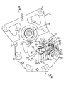
- FIG. 1 is a side view of a brake built-in transmission according to the present invention for driving a wheel such as an electric forklift as viewed from the inside of the vehicle body
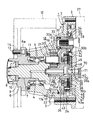
- FIG. 2 is an enlarged vertical front view taken along line II-II in FIG.
- the left and right are referred to in FIG.
- a cover plate 2 as a side wall is fixed to the opening surface on the right side of the mission case 1 by a plurality of bolts 3, and an output shaft 4 is provided at the left end portion in the mission case 1 at the left end. Projecting to the left side of the mission case 1 and supported rotatably by a bearing 5.
- a wheel shaft 6 is externally fitted to the left end portion of the output shaft 4 through a spline 7 so as not to be relatively rotatable, and a nut 10 screwed to a small diameter screw shaft 8 at the left end portion of the output shaft 4 through a washer 9. Thus, it is integrally coupled to the output shaft 4.
- the outer peripheral surface of the right end portion of the wheel shaft 6 is rotatably supported by the bearing 5 on the inner surface of the left end portion of the mission case 1.
- 11 is a seal member that is press-fitted to the inner peripheral surface of the left end of the transmission case 1, and the lubricant supplied to the transmission case 1 leaks to the outside by slidingly contacting the outer peripheral surface of the wheel shaft 6. It is preventing.
- the wheel 12 is fixed to the diameter-enlarging flange 6 a of the wheel shaft 6 by a plurality of bolts 13 and nuts 14.
- a central sun gear 15, a plurality of (for example, three) planet gears 16 that mesh with the sun gear 15, and an inner gear 17 a that meshes with each planet gear 16 so as to surround each planet gear 16 are disposed at the center of the transmission case 1.
- a planetary gear unit 18 including a ring gear 17 on the inner peripheral surface is accommodated.
- the connecting piece 21 is press-fitted.
- the ring gear 17 is fixed by being press-fitted into the stepped hole 22 on the inner surface of the mission case 1. Thereby, when the sun gear 15 rotates, each planet gear 16 revolves along the internal teeth 17a of the ring gear 17 while rotating, and the output shaft 4 is decelerated and rotated.
- a large-diameter drive shaft 23 that drives the sun gear 15 is provided concentrically and integrally with the sun gear 15.
- a cylindrical shaft 24a at the center of the drive gear 24 is fitted on the outer peripheral surface of the drive shaft 23 through a spline 25 that engages with each other so as not to be relatively rotatable.
- the drive gear 24 has an annular concave portion 26 that opens to the cover plate 2 side on the right side surface facing the cover plate 2 and has a small axial dimension and a substantially U-shaped cross section facing right. .
- the left end portion of the input shaft 28 that is driven by being linked to the electric drive unit 27 on the vehicle body side to which the mission case 1 is attached penetrates the cover plate 2 and enters the right end portion at the top of the mission case 1.
- a cylindrical input gear 31 having cylindrical support shafts 30a and 30b facing the axial direction at both left and right ends is fitted on a spline 29 formed on the outer peripheral surface of the left end portion of the input shaft 28 so as not to be relatively rotatable. Has been.
- the input gear 31 meshes with the drive gear 24.
- the outer peripheral surface of the left support shaft 30a of the input gear 31 is rotatably supported by a bearing 33 press-fitted in the stepped hole 32 of the transmission case 1, and the outer peripheral surface of the right support shaft 30b is also a cover plate. 2 is rotatably supported by a bearing 35 press-fitted into the insertion hole 34 of the support shaft 30b. Thereby, the input gear 31 is substantially supported by the transmission case 1 and the cover plate 2 and is stably supported.
- a multi-plate type disc brake unit 36 is assembled as follows.
- the disc brake unit 36 includes a plurality of rotation-side brake discs 37, a plurality of fixed-side brake discs 38 alternately sandwiched so as to overlap in the axial direction between the rotation-side brake discs 37 adjacent to each other, and the rightmost side.
- a disc-shaped pressure plate 39 capable of axially pushing the right side surface of the fixed-side brake disc 38 positioned at a position, and a pushing arm 71 described later capable of pushing the central portion of the pressure plate 39 to the left side.
- a press rod 40 linked thereto.
- a concave / convex portion (not shown) formed in a circular hole at the center of each rotation-side brake disc 37 is formed on the spline 25 on the outer peripheral surface of the drive shaft 23 that protrudes to the right side of the drive gear 24. It is fitted so as to be movable, and can rotate integrally with the drive shaft 23.
- each fixed-side brake disc 38 is formed on the left side surface of the cover plate 2 in the cylindrical portion 41 projecting inward so as to surround the right end portion of the drive shaft 23.
- a spline 42 formed on the surface is fitted in an axially movable and non-rotatable manner.
- the cover plate 2 is fixed to the inner end surface of the cylindrical portion 41 by a plurality of bolts 44.
- the inner end portion of the disk holding plate 43 is prevented from obstructing the rotation of the drive gear 24 by a bearing 45 interposed between the inner peripheral surface thereof and the outer peripheral surface of the cylindrical shaft 24a of the drive gear 24.
- the drive gear 24 is supported by a cylindrical shaft 24a.
- the pressing rod 40 is fitted in a shaft hole 46 formed in the cover plate 2 in the left-right direction so as to be slidable in the axial direction, and a left end of the pressing rod 40 is formed in the central portion of the pressure plate 39.
- the circular bulging portion 39a bulging to the side is in contact with the center of the back surface of the right side surface.
- a plurality of (for example, three) protrusions 43a that are integrally protruded at equal intervals in the circumferential direction on the outer peripheral surface of the disk holding plate 43 are formed with concave holes 47 that open in the cover plate 2 direction.
- a return spring (compression coil spring) 49 is loosely fitted to the guide pin 48 press-fitted into the concave hole 47 from the inside of the protrusion 43a.
- a plurality of projecting pieces 39b are provided on the outer peripheral surface of the pressure plate 39 so as to face each of the projecting portions 43a.
- the right end of the return spring 49 is in pressure contact with the left side surface of the projecting piece 39b. It is always urged in the direction away from the right side, that is, the rightmost fixed brake disc 38.
- a block plate 50 having a substantially rectangular shape in a side view with a large plate thickness is located slightly rearward of a portion corresponding to the above-described disc brake unit 36 on the right side surface of the cover plate 2.
- a bottomed cylinder chamber 52 that opens to the right side, a first oil passage 53 that communicates with the vicinity of the bottom of the cylinder chamber 52, parallel to the block plate 50, and the first oil A second oil passage 54 is formed which communicates with the passage 53 internally and opens in the right side surface of the block plate 50 in the thickness direction.
- the open end of the second oil passage 54 is a large-diameter female screw hole 55, and a threaded nipple 57 connected to a hydraulic pipe 56 is screwed into the female screw hole 55.
- the other end of the hydraulic pipe 56 is connected to a brake hydraulic cylinder (both not shown) in which a piston interlocked with a vehicle brake pedal is housed.
- a brake hydraulic cylinder both not shown
- the pressure oil in the brake hydraulic cylinder is Is supplied to the first and second oil passages 53 and 54 and the cylinder chamber 52 via the hydraulic pipe 56.
- Reference numeral 58 denotes a closing screw that tightly plugs the opening end of the first oil passage 53 formed by a drill.
- hydraulic pistons 61 each having a concave oil chamber 59 and a conical recess 60 are slidably fitted on the left side surface and the right side surface, respectively.
- a seal member 63 for preventing leakage of pressurized oil from the cylinder chamber 52 is fitted in an annular groove 62 formed on the outer peripheral surface of the hydraulic piston 61.
- a cylindrical projection 65 having an annular locking groove 64 formed on the outer peripheral surface is provided so as to communicate with the cylinder chamber 52.
- the cylindrical projecting portion 65 has an annular pin holding member 66 in which an inner cylindrical portion 66b that is open in both the left and right directions is integrally formed at the center of the outer cylindrical portion 66a that is open at the left end.
- An annular engaging protrusion 67 protruding from the inner surface of the left end portion of 66a is fixed by elastically engaging the locking groove 64.
- a pin 68 facing both the left and right directions whose both end surfaces are spherical is fitted and held in the inner cylindrical portion 66b. The pin 68 can be tilted with respect to the hydraulic piston 61 by bringing the spherical left end surface into contact with the inner surface of the concave portion 60 on the right side surface of the hydraulic piston 61.
- a pair of upper and lower support pieces 70 facing the right side are provided in a portion facing the block plate 50.
- a front arm portion 71a on the front side of the push arm 71 having a substantially crank-like cross section in a side view is provided between the support pieces 70 in a side view. It is pivotally attached so as to be able to rotate in the left-right direction by a support shaft 72 that faces substantially in the vertical direction (see FIGS. 1 and 3).
- a long groove 73 facing in the left-right direction is formed on the left side surface of the front end portion of the forward arm portion 71a, and the right end surface of the pressing rod 40 protruding from the cover plate 2 is brought into contact with the inner surface of the long groove 73. .
- the rear arm 71b on the rear side of the push arm 71 is opposed to the hydraulic piston 61 on the right side away from the block plate 50, and is a spherical recess formed on the left side surface of the rear arm 71b.
- the right end surface of the pin 68 is brought into contact with the inner surface of the hole 74.
- the size of the recessed hole 74 is larger than the diameter of the pin 68 so that the pin 68 can tilt with respect to the rear arm portion 71b.
- a cable mounting screw 76 is screwed into a female screw hole 75 having a bottom and formed in the rear end portion of the rear arm portion 71b.
- the cable has one end connected to the cable mounting screw 76.
- the other end of 77 is connected to an operating lever (not shown) for parking brake.
- the pressure oil from the brake hydraulic cylinder is supplied to the first and second oil passages 53 and 54 provided in the block plate 50 via the hydraulic pipe 56. Then, it is pumped into the oil chamber 59 at the bottom of the cylinder chamber 52 and the left end surface of the hydraulic piston 61.
- the hydraulic piston 61 and the pin 68 whose left end is in contact with the concave portion 60 on the right end surface thereof are moved to the right side of the cover plate 2 so that the push arm 71 is indicated by an arrow in FIG. Then, it pivots rightward about the support shaft 72.
- the spherical left end surface and right end surface of the pin 68 are respectively formed into a conical concave portion 60 of the hydraulic piston 61 and a spherical concave hole 74 of the rear arm portion 71b of the push arm 71. Since the pin 68 can be tilted by contact, there is no fear that a bending load is applied to the hydraulic piston 61 and the pin 68, and the push arm 71 can also rotate without resistance.
- the push arm 71 When parking, etc., when the parking brake operating lever is pulled, the push arm 71 is rotated via the cable 77 connected thereto, so that the wheel 12 is prevented from rotating by the same action as described above. Is done.
- the parking brake operating lever When the parking brake operating lever is pulled to rotate the push arm 71, the rear arm 71b is separated from the right end of the pin 68.
- the pin 68 is a pin holding member 66. Therefore, there is no possibility of dropping from the recess 60 of the hydraulic piston 61.
- one push arm 71 is formed by two systems of pressure oil when the brake pedal is depressed and the cable 77 connected to the operation lever for the parking brake. Since the wheel 12 can be rotated to apply a braking force, the structure is simplified.
- the hydraulic piston 61 actuated by the pressure oil is accommodated in the cylinder chamber 52 inside the block plate 50 that is substantially integrated with the cover plate 2, and the pressing force of the hydraulic piston 61 is pushed via the pin 68. Since a hydraulic pipe 56 that transmits to the moving arm 71 and supplies pressure oil to the cylinder chamber 52 is attached to the non-moving block plate 50, the hydraulic pressure is applied each time the brake is applied by the brake pedal as in the prior art. The pipe 56 is prevented from moving frequently with the pushing arm 71. Therefore, there is no fear that the hydraulic oil leaks due to a crack or the like in the hydraulic pipe 56, and the durability of the hydraulic pipe 56 can be improved.
- a separate block plate 50 is screwed to the right side surface of the cover plate 2 that is the side wall of the transmission case 1, and the cylinder chamber 52 provided inside the block plate 50 is attached to the cylinder chamber 52.
- the hydraulic piston 61 is accommodated, but the entire cover plate 2 or a part near the pressure plate 39 is made thick, and the hydraulic piston 61 is accommodated in a cylinder chamber provided in the thick cover plate. You may do it. If it does in this way, since the block board 50 becomes unnecessary, a number of parts and an assembly man-hour can be reduced.
- the pin 68 may be integrally connected to the hydraulic piston 61, so that it is not necessary to separately manufacture the pin 68 and the pin holding member 66 is not required. Therefore, the number of parts and the cost are reduced.
- the pin 61 as described above may be omitted, and the rear arm portion 71b of the push arm 71 may be directly pushed by the outer surface of the hydraulic piston 61 formed in a long shape.
Landscapes
- Engineering & Computer Science (AREA)
- Mechanical Engineering (AREA)
- Transportation (AREA)
- General Engineering & Computer Science (AREA)
- Chemical & Material Sciences (AREA)
- Combustion & Propulsion (AREA)
- Braking Arrangements (AREA)
- General Details Of Gearings (AREA)
Abstract
油圧ピストン及びこれに圧油を供給する油圧パイプを、不動部材に設けることにより、油圧パイプに亀裂等が発生するのを防止しうるようにした、車両用ブレーキ内蔵トランスミッションを提供する。 ミッションケースのカバープレート2に設けた押動アーム側に開口するシリンダ室52に、油圧ピストン61を、押動アーム71の後向アーム部71bに当接して、押動アーム71を回動させうるようにして収容し、かつカバープレート2に、シリンダ室52に圧油を供給する油圧パイプ56を接続する。
Description
本発明は、例えば電動フォークリフト等の車両において、電気駆動ユニットと車輪間に配設されるブレーキ内蔵トランスミッションに関する。
この種のブレーキ内蔵トランスミッションとしては、例えば特許文献1に記載されているように、電動モータにより駆動されるドライブギヤと、このドライブギヤに連係された遊星歯車ユニットと、ドライブギヤと遊星歯車ユニットとの間に設けられたディスクブレーキユニットとを備え、このディスクブレーキユニットのブレーキディスクの側面を、プレッシャプレートにより押圧することにより、ドライブギヤから遊星歯車ユニットに伝達される駆動力を制動するようにしたものがある。
上記特許文献1に記載されているブレーキ内蔵トランスミッションは、この特許文献1の図7に記載されているように、パーキングブレーキ用の操作レバーに連係されて引張られるケーブルと、ブレーキペダル踏み込み時の圧油により作動させられる油圧ピストンとの2系統により、プレッシャプレートが押動されるようにしたものであるが、上記ケーブルの端末と、油圧ピストン及びこれを圧油によりを作動させる油圧パイプとが、共にプレッシャプレートを押圧する押動アームに取付けられているので、ブレーキペダルによりブレーキをかける毎に、油圧パイプが押動アームと共に頻繁に動くこととなる。
そのため、油圧パイプの連結部や支持部等に曲げ荷重が繰り返し作用し、長期間車両を使用した際に、油圧パイプに亀裂が発生するなどして、圧油が漏出する恐れがある。
そのため、油圧パイプの連結部や支持部等に曲げ荷重が繰り返し作用し、長期間車両を使用した際に、油圧パイプに亀裂が発生するなどして、圧油が漏出する恐れがある。
本発明は、上記問題点に鑑みてなされたもので、油圧ピストン及びこれに圧油を供給する油圧パイプを、不動部材に設けることにより、油圧パイプに亀裂等が発生するのを防止しうるようにした、車両用ブレーキ内蔵トランスミッションを提供することを目的としている。
本発明によると、上記課題は、次の各項のようにして解決される。
(1)ミッションケースの側壁を貫通する押圧ロッドの外側端を、前記側壁に回動可能に枢着され、かつパーキングブレーキ用ケーブルと、ブレーキペダルの操作により作動する油圧ピストンとの2系統により回動させられるようにした押動アームの一端部により押動することにより、前記ミッションケース内に収容したディスクブレーキユニットにおけるプレッシャプレートを押圧するようにしてなる車両用ブレーキ内蔵トランスミッションにおいて、前記側壁に設けた前記押動アーム側に開口するシリンダ室に、前記油圧ピストンを、前記押動アームの他端部に当接して、この押動アームを回動させうるようにして収容し、かつ前記側壁に、前記シリンダ室に圧油を供給する油圧パイプを接続する。
(1)ミッションケースの側壁を貫通する押圧ロッドの外側端を、前記側壁に回動可能に枢着され、かつパーキングブレーキ用ケーブルと、ブレーキペダルの操作により作動する油圧ピストンとの2系統により回動させられるようにした押動アームの一端部により押動することにより、前記ミッションケース内に収容したディスクブレーキユニットにおけるプレッシャプレートを押圧するようにしてなる車両用ブレーキ内蔵トランスミッションにおいて、前記側壁に設けた前記押動アーム側に開口するシリンダ室に、前記油圧ピストンを、前記押動アームの他端部に当接して、この押動アームを回動させうるようにして収容し、かつ前記側壁に、前記シリンダ室に圧油を供給する油圧パイプを接続する。
このような構成とすると、ブレーキペダル操作時の圧油により押動アームを回動させる油圧ピストンを、ミッションケースの側壁のシリンダ室に収容し、かつシリンダ室に圧油を供給する油圧パイプを、不動の側壁に接続してあるので、従来のように、ブレーキペダルによりブレーキをかける毎に、油圧パイプが押動アームと共に頻繁に動くのが防止される。従って、油圧パイプに亀裂等が生じるなどして、圧油が漏出する恐れはなく、かつ油圧パイプの耐久性を向上させることができる。
(2)上記(1)項において、押動アームと油圧ピストンとの間に、ピンを、前記油圧ピストンに対して傾動しうるように介在させる。
このような構成とすると、ピンにより押動アームを回動させる際、ピンが油圧ピストンに対して傾動するので、油圧ピストンやピンに曲げ荷重が加わることがなく、かつ押動アームも抵抗なく回動することができる。
(3)上記(2)項において、油圧ピストンにおける押動アームと対向する側の端面に、円錐状の凹部を設け、この凹部の奥面に、油圧ピストン側の端面を球面状としたピンを、傾動可能に当接させる。
このような構成とすると、油圧ピストンの凹部を中心として、ピンを安定よく傾動させることができる。
(4)上記(1)項において、油圧ピストンの外側面に、押動アーム側の端面を球面状としたピンを一体的に突設し、前記球面状とした端面を、押動アームの他端部に当接させる。
このような構成とすると、ピンを別途製作する必要がなく、かつピンを保持する部材も不要となるので、部品点数や組付工数、及びコストが削減される。
本発明によれば、ブレーキペダルによりブレーキをかける毎に、油圧パイプが押動アームと共に頻繁に動くのが防止されるので、油圧パイプに亀裂等が生じるなどして、圧油が漏出する恐れはなく、かつ油圧パイプの耐久性を向上させることができる。
以下、本発明の実施形態を、図面に基づいて説明する。
図1は、電動フォークリフト等の車輪を駆動する本発明のブレーキ内蔵トランスミッションを、車体の内方より見た側面図、図2は、図1のII‐II線拡大縦断正面図である。なお、以下の説明において、左右は、図2に関して言うものとする。
図1は、電動フォークリフト等の車輪を駆動する本発明のブレーキ内蔵トランスミッションを、車体の内方より見た側面図、図2は、図1のII‐II線拡大縦断正面図である。なお、以下の説明において、左右は、図2に関して言うものとする。
図2において、ミッションケース1の右側面の開口面には、側壁としてのカバープレート2が、複数のボルト3により固定され、ミッションケース1内の左半部には、アウトプットシャフト4が、左端部をミッションケース1の左側方に突出させて、ベアリング5により回転自在に支持されている。
アウトプットシャフト4の左端部には、ホイールシャフト6が、スプライン7を介して相対回転不能に外嵌され、アウトプットシャフト4の左端部の小径ねじ軸8にワッシャ9を介して螺合されたナット10により、アウトプットシャフト4に一体的に結合されている。
ホイールシャフト6の右端部の外周面は、ベアリング5によりミッションケース1の左端部の内面に回転自在に支持されている。11は、ミッションケース1の左端の内周面に圧嵌されたシール部材で、ホイールシャフト6の外周面に摺接することにより、ミッションケース1に供給される潤滑油が外部に洩出するのを防止している。
ホイールシャフト6の拡径フランジ6aには、車輪12が、複数のボルト13とナット14により固定されている。
ミッションケース1内の中央部には、中心のサンギヤ15と、このサンギヤ15に噛合する複数(例えば3個)のプラネットギヤ16と、各プラネットギヤ16を囲むようにして、それらに噛合する内噛17aを内周面に有するリングギヤ17とからなる遊星歯車ユニット18が収容されている。
上記プラネットギヤ16の中心に、ベアリング19を介して回転自在に嵌合されている左右方向を向く支軸20の左方の突出端部は、アウトプットシャフト4の右端の外周面に突設された連結片21に圧嵌されている。
リングギヤ17は、ミッションケース1の内面の段付孔22に圧嵌して固定されている。これにより、サンギヤ15が回転すると、各プラネットギヤ16は、自転しながらリングギヤ17の内歯17aに沿って公転し、アウトプットシャフト4が減速されて回転されるようになる。
サンギヤ15の右端には、これを駆動する大径のドライブシャフト23が、サンギヤ15と同心的に一体的に連設されている。
ドライブシャフト23の外周面には、ドライブギヤ24の中心の円筒軸24aが、互いに係合し合うスプライン25を介して、相対回転不能に外嵌されている。
ドライブギヤ24は、カバープレート2と対向する右側面に、カバープレート2側に開口する環状の凹部26が形成された、軸方向の寸法が小さい、正面視ほぼ右向きコ字状断面のものである。
ミッションケース1が取付けられる車体側の電気駆動ユニット27に連係されて駆動されるインプットシャフト28の左端部は、カバープレート2を貫通して、ミッションケース1の上部の右側端部内に突入しており、インプットシャフト28の左端部の外周面に形成されたスプライン29には、左右両端に軸方向を向く円筒状の支持軸30a、30bを有する筒状のインプットギヤ31が、相対回転不能に外嵌されている。インプットギヤ31は、上記ドライブギヤ24と噛合している。
インプットギヤ31の左側の支持軸30aの外周面は、ミッションケース1の段付孔32に圧嵌されたベアリング33により回転自在に支持され、また同じく右側の支持軸30bの外周面は、カバープレート2における支持軸30bの挿通孔34に圧嵌されたベアリング35により回転自在に支持されている。これにより、インプットギヤ31は、実質的にミッションケース1とカバープレート2とにより両持ちで、安定的に支持されている。
ドライブギヤ24の凹部26と、それに対向するカバープレート2の左側面との間に形成された空間内には、多板式のディスクブレーキユニット36が、次のようにして組込まれている。
ディスクブレーキユニット36は、複数の回転側ブレーキディスク37と、互いに隣接する回転側ブレーキディスク37間に軸方向に重合するように交互に挟入された複数の固定側ブレーキディスク38と、最右方に位置する固定側ブレーキディスク38の右側面を軸方向に押動可能な円板状のプレッシャプレート39と、このプレッシャプレート39の中心部を左側方に押圧可能な、後記する押動アーム71に連係された押圧ロッド40とを備えている。
各回転側ブレーキディスク37の中心の円孔に形成された凹凸部(図示略)は、ドライブシャフト23におけるドライブギヤ24の右側方に突出する外周面のスプライン25に、相対回転不能かつ軸方向に移動可能に外嵌され、ドライブシャフト23と一体的に回転しうるようになっている。
各固定側ブレーキディスク38の外周の凹凸部(図示略)は、カバープレート2の左側面に、ドライブシャフト23の右側端部を囲むように内向突設された円筒部41内において、その内周面に形成されたスプライン42に、軸方向に移動可能かつ回転不能に内嵌されている。
43は、各回転側ブレーキディスク37及び固定側ブレーキディスク38の左側方への移動を阻止するディスク保持プレートで、最内方の回転側ブレーキディスク37の内側面と当接しうるようにして、かつ内方の一部をドライブギヤ24の凹部26内に収容した状態で、カバープレート2における円筒部41の内端面に、複数のボルト44により固着されている。
ディスク保持プレート43の内端部は、その内周面と、ドライブギヤ24の円筒軸24aの外周面との間に介設したベアリング45により、ドライブギヤ24の回転に支障を来たさないように、このドライブギヤ24の円筒軸24aにより支持されている。
押圧ロッド40は、カバープレート2に形成された左右方向を向く軸孔46に、軸方向に摺動可能に嵌合され、その左端は、プレッシャプレート39の中央部に形成された、ドライブギヤ23側に膨出する円形の膨出部39aにおける右側面の奥面中央と当接するようにしてある。
ディスク保持プレート43の外周面に、円周方向に等間隔をもって一体的に突設された複数(例えば3個)の突部43aには、カバープレート2方向に開口する凹孔47が形成され、突部43aの内方より、凹孔47内に圧入されたガイドピン48には、リターンばね(圧縮コイルばね)49が遊嵌されている。
プレッシャプレート39の外周面には、上記各突部43aと対向する突片39bが複数突設され、この突片39bの左側面に、リターンばね49の右端が圧接することにより、プレッシャプレート39は、常時右側方、すなわち最右方の固定側ブレーキディスク38と離れる方向に付勢されている。
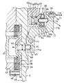
図1、図3及び図4に示すように、カバープレート2の右側面における上述したディスクブレーキユニット36と対応する部分のやや後方寄りには、板厚の大きな側面視概ね四角形をなすブロック板50が、複数のねじ51により固着されている。ブロック板50の内部には、右側方に開口する有底のシリンダ室52と、このシリンダ室52の底部付近と連通する、ブロック板50と平行をなす第1油路53と、この第1油路53と内部で連通し、かつ厚さ方向を向いてブロック板50の右側面に開口する第2油路54とが形成されている。
第2油路54の開口端部は、大径のめねじ孔55とされ、このめねじ孔55には、油圧パイプ56を接続してなるねじ付きニップル57が螺着されている。油圧パイプ56の他端部は、車両のブレーキペダルと連動するピストンが収容されたブレーキ用油圧シリンダ(いずれも図示略)に接続され、ブレーキペダルを踏み込んだ際、ブレーキ用油圧シリンダ内の圧油が、油圧パイプ56を介して、第1、第2油路53、54及びシリンダ室52に供給されるようになっている。58は、ドリルで穿設した第1油路53の開口端部を密栓する塞ぎねじである。
シリンダ室52には、左側面と右側面とに、それぞれ凹状の油室59と円錐状の凹部60を形成してなる油圧ピストン61が、摺動可能に嵌合されている。油圧ピストン61の外周面に形成された環状溝62には、シリンダ室52からの圧油の漏出を防止するシール部材63が嵌合されている。
ブロック板50におけるシリンダ室52が形成された部分の右側面には、外周面に環状の係止溝64が形成された筒状突部65が、シリンダ室52と連通するようにして突設され、この筒状突部65には、左側端が開口する外筒部66aの中心部に、左右両方向に開口する内筒部66bが一体形成された環状をなすピン保持部材66が、外筒部66aの左端部の内面に突設された環状の係合突部67を、上記係止溝64に弾性係合させることにより止着されている。内筒部66bには、両端面が球面状とされた左右方向を向くピン68が嵌合されて保持されている。ピン68は、その球面状をなす左端面を、上記油圧ピストン61の右側面の凹部60の奥面に当接させることにより、油圧ピストン61に対し傾動可能とされている。
カバープレート2の右側面におけるディスクブレーキユニット36と対応する部分に形成された皿状断面の凹部69内において、上記ブロック板50と対向する部分には、右側方を向く上下1対の支持片70、70が突設され、両支持片70間には、側面視において概ね前後方向を向き、かつ横断面形状がほぼクランク状をなす押動アーム71における前部側の前向アーム部71aが、ほぼ上下方向を向く支軸72により、左右方向に回動しうるように枢着されている(図1、図3参照)。
前向アーム部71aの前端部の左側面には、左右方向を向く長溝73が形成され、この長溝73の奥面に、カバープレート2より突出する押圧ロッド40の右端面を当接させてある。
前向アーム部71aの前端部の左側面には、左右方向を向く長溝73が形成され、この長溝73の奥面に、カバープレート2より突出する押圧ロッド40の右端面を当接させてある。
押動アーム71の後部側の後向アーム部71bは、ブロック板50と離間する右側方において、油圧ピストン61と対向しており、後向アーム部71bの左側面に形成された球面状の凹孔74の奥面に、上記ピン68の右端面を当接させてある。なお、凹孔74の大きさは、ピン68の直径よりも大とされ、後向アーム部71bに対しピン68が傾動しうるようにしてある。
後向アーム部71bの後端部に形成された右側方に開口する有底のめねじ孔75には、ケーブル取付ねじ76が螺着され、このケーブル取付ねじ76に一端部が連結されたケーブル77の他端部は、パーキングブレーキ用の操作レバー(図示略)に連結されている。
上記実施形態のブレーキ内蔵トランスミッションにおいて、ブレーキペダルを踏み込むと、ブレーキ用油圧シリンダからの圧油が、油圧パイプ56を介して、ブロック板50に設けた第1、第2油路53、54に供給され、シリンダ室52の底部と油圧ピストン61の左端面の油室59内に圧送される。
すると、油圧ピストン61、及びその右端面の凹部60に左端が当接しているピン68が、カバープレート2の右側方に移動させられることにより、押動アーム71は、図3に矢印で示すように、支軸72を中心として右側方に回動する。この際、ピン68における球面状とされた左端面と右端面は、それぞれ、油圧ピストン61の円錐状の凹部60と、押動アーム71の後向アーム部71bの球面状の凹孔74とに当接し、ピン68は傾動可能となっているので、油圧ピストン61やピン68に曲げ荷重が加わる恐れはなく、かつ押動アーム71も抵抗なく回動することができる。
これにより、押動アーム71の前向アーム部71aが左方に回動し、その前端部の左側面に当接している押圧ロッド40、及びこの左端面に当接しているプレッシャプレート39が左方に押動させられる。
その結果、プレッシャプレート39の外周端部と対向している最右方の固定側ブレーキディスク38が左方に押圧されることにより、全てのブレーキディスク37、38同士が互いに圧接し、ドライブギヤ24と一体的に回転するドライブシャフト23、遊星歯車ユニット18、及びアウトプットシャフト4の回転が規制され、車輪12に制動力が働く。
その結果、プレッシャプレート39の外周端部と対向している最右方の固定側ブレーキディスク38が左方に押圧されることにより、全てのブレーキディスク37、38同士が互いに圧接し、ドライブギヤ24と一体的に回転するドライブシャフト23、遊星歯車ユニット18、及びアウトプットシャフト4の回転が規制され、車輪12に制動力が働く。
駐車する際等において、パーキングブレーキ用の操作レバーを引くと、それに連結されたケーブル77を介して、押動アーム71が回動させられるので、上記と同様の作用により、車輪12の回転が阻止される。なお、パーキングブレーキ用の操作レバーを引いて押動アーム71を回動させた際には、後向アーム部71bがピン68の右端から離間することとなるが、ピン68は、ピン保持部材66により保持されているので、油圧ピストン61の凹部60より脱落する恐れはない。
以上説明したように、上記実施形態のブレーキ内蔵トランスミッションにおいては、ブレーキペダル踏み込み時の圧油と、パーキングブレーキ用の操作レバーに連結されたケーブル77との2系統により、一つの押動アーム71を回動させて、車輪12に制動力を付与することができるので、構造が簡素化する。
また、圧油により作動させられる油圧ピストン61を、カバープレート2と実質的に一体をなすブロック板50の内部のシリンダ室52に収容し、油圧ピストン61の押圧力を、ピン68を介して押動アーム71に伝達するようにし、かつシリンダ室52に圧油を供給する油圧パイプ56を、不動のブロック板50に取付けてあるので、従来のように、ブレーキペダルによりブレーキをかける毎に、油圧パイプ56が押動アーム71と共に頻繁に動くのが防止される。従って、油圧パイプ56に亀裂等が生じるなどして、圧油が漏出する恐れはなく、かつ油圧パイプ56の耐久性を向上させることができる。
なお、上記実施形態においては、ミッションケース1の側壁であるカバープレート2の右側面に、これとは別体のブロック板50をねじ止めし、このブロック板50の内部に設けたシリンダ室52に、油圧ピストン61を収容しているが、カバープレート2全体、もしくは、プレッシャプレート39付近の一部を厚肉とし、この厚肉としたカバープレートに設けたシリンダ室に、油圧ピストン61を収容するようにしてもよい。このようにすると、ブロック板50が不要となるので、部品点数や組付工数を削減することができる。
また、図5に示すように、油圧ピストン61に、ピン68を一体的に連設してもよく、このようにすると、ピン68を別途製作する必要がなく、かつピン保持部材66も不要となるので、部品点数及びコストが削減される。
さらに、上記のようなピン61を省略し、長寸に形成した油圧ピストン61の外側面により、押動アーム71の後向アーム部71bを直接押動させるようにすることもある。
1 ミッションケース
2 カバープレート(側壁)
3 ボルト
4 アウトプットシャフト
5 ベアリング
6 ホイールシャフト
6a拡径フランジ
7 スプライン
8 小径ねじ軸
9 ワッシャ
10 ナット
11 シール部材
12 車輪
13 ボルト
14 ナット
15 サンギヤ
16 プラネットギヤ
17 リングギヤ
17a内歯
18 遊星歯車ユニット
19 ベアリング
20 支軸
21 連結片
22 段付孔
23 ドライブシャフト
24 ドライブギヤ
24a円筒軸
25 スプライン
26 凹部
27 電気駆動ユニット
28 インプットブシャフト
29 スプライン
30a支持軸
30b支持軸
31 インプットギヤ
32 段付孔
33 ベアリング
34 挿通孔
35 ベアリング
36 ディスクブレーキユニット
37 回転側ブレーキディスク
38 固定側ブレーキディスク
39 プレッシャプレート
39a膨出部
39b突片
40 押圧ロッド
41 円筒部
42 スプライン
43 ディスク保持プレート
43a突部
44 ボルト
45 ベアリング
46 軸孔
47 凹孔
48 ガイドピン
49 リターンばね
50 ブロック板
51 ねじ
52 シリンダ室
53 第1油路
54 第2油路
55 めねじ孔
56 油圧パイプ
57 ねじ付きニップル
58 塞ぎねじ
59 油室
60 凹部
61 油圧ピストン
62 環状溝
63 シール部材
64 係止溝
65 環状突部
66 ピン保持部材
66a外筒部
66b内筒部
67 係合突部
68 ピン
69 凹部
70 支持片
71 押動アーム
71a前向アーム部
71b後向アーム部
72 支軸
73 長溝
74 凹孔
75 めねじ孔
76 ケーブル取付ねじ
77 ケーブル
Claims (4)
- ミッションケースの側壁を貫通する押圧ロッドの外側端を、前記側壁に回動可能に枢着され、かつパーキングブレーキ用ケーブルと、ブレーキペダルの操作により作動する油圧ピストンとの2系統により回動させられるようにした押動アームの一端部により押動することにより、前記ミッションケース内に収容したディスクブレーキユニットにおけるプレッシャプレートを押圧するようにしてなる車両用ブレーキ内蔵トランスミッションにおいて、
前記側壁に設けた前記押動アーム側に開口するシリンダ室に、前記油圧ピストンを、前記押動アームの他端部に当接して、この押動アームを回動させうるようにして収容し、かつ前記側壁に、前記シリンダ室に圧油を供給する油圧パイプを接続したことを特徴とする車両用ブレーキ内蔵トランスミッション。 - 押動アームと油圧ピストンとの間に、ピンを、前記油圧ピストンに対して傾動しうるように介在させてなる請求項1記載の車両用ブレーキ内蔵トランスミッション。
- 油圧ピストンにおける押動アームと対向する側の端面に、円錐状の凹部を設け、この凹部の奥面に、油圧ピストン側の端面を球面状としたピンを、傾動可能に当接させてなる請求項2記載の車両用ブレーキ内蔵トランスミッション。
- 油圧ピストンの外側面に、押動アーム側の端面を球面状としたピンを一体的に突設し、前記球面状とした端面を、押動アームの他端部に当接させてなる請求項1記載の車両用ブレーキ内蔵トランスミッション。
Priority Applications (3)
| Application Number | Priority Date | Filing Date | Title |
|---|---|---|---|
| CN201080064440.3A CN102762419B (zh) | 2010-02-25 | 2010-10-25 | 车辆用制动器内置型变速器 |
| EP10846593.1A EP2540586B1 (en) | 2010-02-25 | 2010-10-25 | Transmission with built-in brake for vehicles |
| US13/580,839 US8783434B2 (en) | 2010-02-25 | 2010-10-25 | Vehicle transmission with built-in brake |
Applications Claiming Priority (2)
| Application Number | Priority Date | Filing Date | Title |
|---|---|---|---|
| JP2010-040085 | 2010-02-25 | ||
| JP2010040085A JP5559568B2 (ja) | 2010-02-25 | 2010-02-25 | 車両用ブレーキ内蔵トランスミッション |
Publications (1)
| Publication Number | Publication Date |
|---|---|
| WO2011104930A1 true WO2011104930A1 (ja) | 2011-09-01 |
Family
ID=44506368
Family Applications (1)
| Application Number | Title | Priority Date | Filing Date |
|---|---|---|---|
| PCT/JP2010/068813 Ceased WO2011104930A1 (ja) | 2010-02-25 | 2010-10-25 | 車両用ブレーキ内蔵トランスミッション |
Country Status (5)
| Country | Link |
|---|---|
| US (1) | US8783434B2 (ja) |
| EP (1) | EP2540586B1 (ja) |
| JP (1) | JP5559568B2 (ja) |
| CN (1) | CN102762419B (ja) |
| WO (1) | WO2011104930A1 (ja) |
Families Citing this family (2)
| Publication number | Priority date | Publication date | Assignee | Title |
|---|---|---|---|---|
| JP5795234B2 (ja) * | 2011-10-14 | 2015-10-14 | 住友重機械工業株式会社 | 車輪駆動用の減速装置 |
| CN103453079A (zh) * | 2013-09-09 | 2013-12-18 | 山东临沂临工汽车桥箱有限公司 | 一种汽油微型货车变速器 |
Citations (3)
| Publication number | Priority date | Publication date | Assignee | Title |
|---|---|---|---|---|
| JPS5010984A (ja) * | 1973-05-28 | 1975-02-04 | ||
| JPH02173470A (ja) * | 1988-12-23 | 1990-07-04 | Aisin Aw Co Ltd | バンドブレーキ用サーボ装置 |
| US5147255A (en) | 1990-04-03 | 1992-09-15 | Hurth Getriebe Und Zahnraeder G.M.B.H. | Spur gear transmission, in particular for a drive unit of an industrial truck |
Family Cites Families (7)
| Publication number | Priority date | Publication date | Assignee | Title |
|---|---|---|---|---|
| US2263505A (en) * | 1941-05-19 | 1941-11-18 | Homer T Lambert | Brake construction |
| US2981376A (en) * | 1958-01-27 | 1961-04-25 | Borg Warner | Disc brake |
| US3332518A (en) * | 1965-02-04 | 1967-07-25 | Gen Motors Corp | Disc brake caliper having an outwardly actuated wheel cylinder |
| US3647031A (en) * | 1969-10-03 | 1972-03-07 | Bendix Corp | Parking brake actuator for disc brakes |
| JPS5010984U (ja) * | 1973-05-26 | 1975-02-04 | ||
| US5174419A (en) | 1990-04-03 | 1992-12-29 | Hurth Getriebe Und Zahnraeder G.M.B.H | Spur gear transmission for a drive unit of an industrial truck with lever mounted hydraulic cylinder |
| WO2007119577A1 (ja) * | 2006-03-24 | 2007-10-25 | Komatsu Utility Co., Ltd. | バッテリフォークリフト用ドライブユニット |
-
2010
- 2010-02-25 JP JP2010040085A patent/JP5559568B2/ja active Active
- 2010-10-25 WO PCT/JP2010/068813 patent/WO2011104930A1/ja not_active Ceased
- 2010-10-25 CN CN201080064440.3A patent/CN102762419B/zh active Active
- 2010-10-25 EP EP10846593.1A patent/EP2540586B1/en not_active Not-in-force
- 2010-10-25 US US13/580,839 patent/US8783434B2/en active Active
Patent Citations (3)
| Publication number | Priority date | Publication date | Assignee | Title |
|---|---|---|---|---|
| JPS5010984A (ja) * | 1973-05-28 | 1975-02-04 | ||
| JPH02173470A (ja) * | 1988-12-23 | 1990-07-04 | Aisin Aw Co Ltd | バンドブレーキ用サーボ装置 |
| US5147255A (en) | 1990-04-03 | 1992-09-15 | Hurth Getriebe Und Zahnraeder G.M.B.H. | Spur gear transmission, in particular for a drive unit of an industrial truck |
Non-Patent Citations (1)
| Title |
|---|
| See also references of EP2540586A4 |
Also Published As
| Publication number | Publication date |
|---|---|
| EP2540586A1 (en) | 2013-01-02 |
| US20120318631A1 (en) | 2012-12-20 |
| JP5559568B2 (ja) | 2014-07-23 |
| EP2540586B1 (en) | 2015-08-26 |
| CN102762419B (zh) | 2015-01-07 |
| US8783434B2 (en) | 2014-07-22 |
| JP2011173548A (ja) | 2011-09-08 |
| CN102762419A (zh) | 2012-10-31 |
| EP2540586A4 (en) | 2013-10-02 |
Similar Documents
| Publication | Publication Date | Title |
|---|---|---|
| CN102297223A (zh) | 盘式制动器 | |
| US8069961B2 (en) | Disk brake apparatus | |
| US20140090933A1 (en) | Disc brake | |
| CN102272483B (zh) | 包含湿式制动器的传动装置 | |
| JP5460596B2 (ja) | ハイドロリックエレメント | |
| CN103032498A (zh) | 盘式制动器 | |
| US5147255A (en) | Spur gear transmission, in particular for a drive unit of an industrial truck | |
| JP5559568B2 (ja) | 車両用ブレーキ内蔵トランスミッション | |
| CN101784810B (zh) | 用于停车制动的致动器 | |
| JP2013217468A (ja) | ディスクブレーキ倍力機構 | |
| US10495164B2 (en) | Wheel type construction machine | |
| KR20220119496A (ko) | 브레이크 장치 | |
| JP4673809B2 (ja) | 車両用ブレーキ内蔵トランスミッション | |
| JP4944725B2 (ja) | 走行車両 | |
| JP5633797B2 (ja) | ディスクブレーキ | |
| KR20090063730A (ko) | 트랙터의 브레이크 작동장치 | |
| KR100583661B1 (ko) | 산업차량의 브레이크장치 | |
| JP2008039099A (ja) | 車両用ブレーキ内蔵トランスミッション | |
| KR102720201B1 (ko) | 지지부재 및 이를 포함하는 전자식 캘리퍼 브레이크 | |
| KR100930117B1 (ko) | 건설장비 차량의 차축 주차브레이크 장치 | |
| WO2019131619A1 (ja) | 電動倍力装置 | |
| JP2012236468A (ja) | クラッチ構造 | |
| JP6715956B2 (ja) | ディスクブレーキ | |
| KR102270706B1 (ko) | 농작업차량 | |
| JP2009127705A (ja) | トラクタ |
Legal Events
| Date | Code | Title | Description |
|---|---|---|---|
| WWE | Wipo information: entry into national phase |
Ref document number: 201080064440.3 Country of ref document: CN |
|
| 121 | Ep: the epo has been informed by wipo that ep was designated in this application |
Ref document number: 10846593 Country of ref document: EP Kind code of ref document: A1 |
|
| WWE | Wipo information: entry into national phase |
Ref document number: 2010846593 Country of ref document: EP |
|
| WWE | Wipo information: entry into national phase |
Ref document number: 13580839 Country of ref document: US |
|
| NENP | Non-entry into the national phase |
Ref country code: DE |