WO2011105006A1 - Terminal et procédé de communication - Google Patents
Terminal et procédé de communication Download PDFInfo
- Publication number
- WO2011105006A1 WO2011105006A1 PCT/JP2011/000398 JP2011000398W WO2011105006A1 WO 2011105006 A1 WO2011105006 A1 WO 2011105006A1 JP 2011000398 W JP2011000398 W JP 2011000398W WO 2011105006 A1 WO2011105006 A1 WO 2011105006A1
- Authority
- WO
- WIPO (PCT)
- Prior art keywords
- audio signal
- communication terminal
- band
- echo
- subband
- Prior art date
- Legal status (The legal status is an assumption and is not a legal conclusion. Google has not performed a legal analysis and makes no representation as to the accuracy of the status listed.)
- Ceased
Links
Images







Classifications
-
- H—ELECTRICITY
- H04—ELECTRIC COMMUNICATION TECHNIQUE
- H04M—TELEPHONIC COMMUNICATION
- H04M9/00—Arrangements for interconnection not involving centralised switching
- H04M9/08—Two-way loud-speaking telephone systems with means for conditioning the signal, e.g. for suppressing echoes for one or both directions of traffic
- H04M9/082—Two-way loud-speaking telephone systems with means for conditioning the signal, e.g. for suppressing echoes for one or both directions of traffic using echo cancellers
-
- H—ELECTRICITY
- H04—ELECTRIC COMMUNICATION TECHNIQUE
- H04B—TRANSMISSION
- H04B3/00—Line transmission systems
- H04B3/02—Details
- H04B3/20—Reducing echo effects or singing; Opening or closing transmitting path; Conditioning for transmission in one direction or the other
- H04B3/23—Reducing echo effects or singing; Opening or closing transmitting path; Conditioning for transmission in one direction or the other using a replica of transmitted signal in the time domain, e.g. echo cancellers
Definitions
- the present invention relates to a communication terminal and communication method for transmitting and receiving audio signals, and more particularly to a communication terminal and communication method for transmitting audio signals subjected to echo cancellation processing.
- the sound of the speaker that outputs the audio signal of the far end is collected by the microphone of the near end (own terminal) and transmitted as an echo to the far end.
- the communication terminal includes an echo canceller.
- the echo canceller here removes echoes that are generated when the speaker and the microphone are installed at positions separated from each other as compared with the case of the mobile phone.
- the above echo canceller has an enormous amount of calculation compared to a simple echo canceller used in a conventional mobile phone. There are two factors.
- the first point is that the audio playback band is widened in order to transmit and receive high-quality audio.
- the reproduction band is a little less than 4 kHz, but the reproduction band of audio used in high-realistic communication is, for example, 12 kHz.
- the second point is that the echo reverberation time is prolonged.
- sound is emitted from a speaker at the ear and picked up by a microphone at the mouth, so that the expected echo reverberation time is about 30 msec at most.
- the speaker is a loud speaker built in the display, and the microphone is installed indoors. And since the said room has a capacity
- the amount of computation of the echo canceller is proportional to the square of the reproduction band and further to the assumed echo reverberation time if the same echo cancellation method is used.
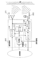
- FIG. 16 is a diagram showing the basic principle of a conventional echo canceller 10. As shown in FIG. 16, the echo canceller 10 removes the echo collected by the microphone 30 from the sound emitted from the speaker 20.
- the echo canceller 10 includes a pseudo echo generation unit 11 and a subtractor 12, and the pseudo echo generation unit 11 uses the input signal and the reference signal from the microphone 30 to connect the speaker 20 and the microphone 30. Estimate the transfer function of the arranged space. Then, the pseudo-echo generation unit 11 configures the estimated transfer function with an adaptive filter having a predetermined number of taps, and generates a pseudo-echo by driving the adaptive filter. Then, the subtracter 12 reduces the echo by subtracting the pseudo echo generated by the pseudo echo generation unit 11 from the input signal input from the microphone 30.
- the echo canceller 10 processes an E ⁇ F tap filter for each sample, the amount of calculation per unit time is (E ⁇ F) ⁇ F. That is, the calculation amount of the echo canceller 10 is proportional to the echo reverberation time E and proportional to the square of the sampling frequency F.
- Non-Patent Document 1 There is a sub-band echo canceller as a known technique for reducing the amount of computation of an echo canceller that cancels echoes in a space where a speaker and a microphone are set apart from each other (see Non-Patent Document 1).
- the input signal is divided into a plurality of subband signals and simultaneously downsampled. For example, if the signal is divided into 20 subbands and 1/16 downsampling is performed, the amount of calculation is E ⁇ (F / 16) ⁇ (F / 16) ⁇ 20 + ⁇ . ⁇ is a calculation amount for subband division. If ⁇ is sufficiently small, the amount of calculation can be reduced to 20/256 compared to a normal echo canceller.
- Patent Document 1 discloses a technique for reducing the amount of calculation in a subband echo canceller by increasing or decreasing the number of taps of the adaptive filter of the echo canceller of each band according to the sound source. Has been.
- the above conventional technique has a problem that the amount of calculation of the echo canceller is not sufficiently reduced.
- the calculation amount of the echo canceller is 180 times different between the conventional mobile phone and the highly realistic communication system. Compared to the case of a mobile phone, the increase in the calculation amount is 180 ⁇ 20 / 256 ⁇ 14 times.
- the present invention has been made in view of the above-described conventional problems, and an object thereof is to provide a communication terminal and a communication method that can further reduce the amount of calculation required for echo cancellation processing.
- a communication terminal is a communication terminal that performs voice signal communication with another communication terminal, and the input bit received from the other communication terminal.
- An output audio signal is generated by decoding the stream, and the input audio signal collected by a decoding unit that outputs the generated output audio signal to a speaker and a microphone installed in a space where the speaker outputs sound is acquired.
- An echo cancellation unit that generates a transmission audio signal by removing an echo component included in the acquired input audio signal and corresponding to the output audio signal generated by the decoding unit for each subband; and the transmission audio An encoding unit that generates an output bitstream by encoding the signal and transmits the generated output bitstream to the other communication terminal; and the output audio signal and the transmission In response to at least one of the regeneration zone of use audio signal, and a control unit for controlling the echo cancellation performance by the echo canceller in each subband.
- the echo cancellation processing performance is controlled according to the reproduction band of at least one of the output audio signal and the transmission audio signal, the amount of calculation required for the echo cancellation processing can be further reduced.
- the echo cancellation unit generates the transmission audio signal by applying a filter with a predetermined number of taps to the input audio signal for each subband, and the control unit generates the output audio signal and The number of taps may be set for each subband according to at least one reproduction band of the transmission audio signal.
- the control unit may set the number of filter taps to be applied to 0 in at least one subband including a frequency band equal to or higher than at least one reproduction band of the output audio signal and the transmission audio signal.
- the calculation amount can be further reduced.
- the calculation amount can be further reduced by setting so as not to perform unnecessary echo cancellation processing. it can.
- control unit may execute an echo cancellation process only on a subband including a frequency band equal to or lower than a reproduction band of at least one of the output audio signal and the transmission audio signal.
- the calculation amount can be further reduced by setting so as not to perform unnecessary echo cancellation processing. it can.
- control unit further determines a type of codec used when the other communication terminal encodes or decodes an audio signal, thereby at least one of the output audio signal and the transmission audio signal.
- a determination unit that determines a reproduction band may be provided, and the control unit may control the echo cancellation processing performance according to the reproduction band determined by the determination unit.
- the playback band can be determined simply by determining the type of codec, so the amount of computation required for echo cancellation processing can be greatly reduced compared to determining the number of taps from the input audio signal. Can do.
- the control unit further includes a determination unit that determines a reproduction band of at least one of the output audio signal and the transmission audio signal by determining a sampling frequency used by the other communication terminal, The control unit may control the echo cancellation processing performance according to the reproduction band determined by the determination unit.
- the playback band can be determined simply by determining the sampling frequency, so that the amount of computation required for echo cancellation processing can be greatly reduced compared to the case where the number of taps is determined from the input audio signal. it can.
- the input bit stream includes a parameter indicating a reproduction band of the output audio signal
- the decoding unit generates the output audio signal and the parameter by decoding the input bit stream, and the control unit Further, the echo cancellation processing performance may be controlled in accordance with a reproduction band indicated by the parameter generated by the decoding unit.
- the amount of calculation required for the echo cancellation process can be greatly reduced as compared with the case where the number of taps is determined from the input audio signal.
- control unit further determines a reproduction band of the audio signal for transmission when the calculation amount by the process executed by the communication terminal exceeds a predetermined threshold, and according to the determined reproduction band, The echo cancellation processing performance may be controlled for each subband.
- the echo cancellation process can be executed with a low amount of calculation.
- the communication terminal further includes a band limiting unit that outputs an output audio signal of a limited reproduction band to the speaker by limiting a reproduction band of the output audio signal
- the control unit further includes: When the amount of computation by the processing executed by the communication terminal exceeds a predetermined threshold, the reproduction band to be limited is determined by the band limiting unit, and the echo cancellation processing performance is set for each subband according to the determined reproduction band. You may control to.
- the echo cancellation process can be executed in this manner, so that it is possible to reduce the deterioration of the voice on the other communication terminal side.
- the communication terminal further includes a reproduction band of an audio signal used when the other communication terminal generates the input bitstream when the amount of calculation performed by the process executed by the communication terminal exceeds a predetermined threshold.
- An instruction unit for transmitting an instruction for restricting to the other communication terminal may be provided.
- the frequency band transmitted to the other communication terminal is limited by limiting the frequency band of the sound output on the communication terminal side in the other communication terminal. Therefore, the echo cancellation process can be executed with a small amount of computation, so that it is possible to reduce the deterioration of voice on the other communication terminal side.
- a communication terminal is a communication terminal that performs audio signal communication with another communication terminal, and outputs an output by decoding an input bitstream received from the other communication terminal.
- a voice signal is generated, a decoding unit that outputs the generated output voice signal to a speaker, and an input voice signal collected by a microphone installed in a space where the speaker emits sound is acquired, and the acquired input voice signal is obtained.
- An echo cancellation unit that generates a transmission audio signal by removing an echo component corresponding to the output audio signal generated by the decoding unit for each subband, and encoding the transmission audio signal.
- an encoding unit that generates an output bitstream and transmits the generated output bitstream to the other communication terminal, and an amount of calculation performed by the communication terminal, Serial echo cancellation performance by the echo canceling part A, and a control section for controlling for each sub-band.
- the echo cancellation process can be executed with a low amount of calculation.
- the echo cancellation unit generates the transmission audio signal by applying a filter with a predetermined number of taps to the input audio signal for each subband, and the control unit is configured to respond to the calculation amount.
- the number of taps may be set for each subband.
- the control unit may include a filter tap to be applied to one or more subbands including a subband including the maximum frequency band and not including the minimum frequency band when the calculation amount exceeds a predetermined threshold.
- the number may be set to zero.
- control unit when the amount of calculation exceeds a predetermined threshold, includes an echo cancellation process only in one or more subbands including a subband including the minimum frequency band and not including the maximum frequency band. May be executed.
- the present invention can be realized not only as a communication terminal but also as a method using a processing unit constituting the communication terminal as a step.
- each of the communication terminals may be configured by one system LSI (Large Scale Integration).
- the system LSI is an ultra-multifunctional LSI manufactured by integrating a plurality of components on one chip. Specifically, a microprocessor, a ROM (Read Only Memory), a RAM (Random Access Memory), etc. It is a computer system comprised including.
- the communication terminal and the communication method according to the present invention it is possible to further reduce the amount of calculation required for echo cancellation processing.
- FIG. 1 is a block diagram showing an example of a configuration of a communication terminal according to Embodiment 1.
- FIG. 2 is a block diagram illustrating an example of a detailed functional configuration of the echo canceller according to the first embodiment.
- FIG. 3 is a diagram for explaining an example of the operation of the echo canceller according to the first embodiment.
- FIG. 4 is a diagram for explaining another example of the operation of the echo canceller according to the first embodiment.
- FIG. 5 is a flowchart illustrating an example of echo cancellation processing according to the first embodiment.
- FIG. 6 is a block diagram showing another example of the configuration of the communication terminal according to Embodiment 1.
- FIG. 7 is a diagram showing an example of frequency characteristics of the output audio signal according to the first embodiment.
- FIG. 8 is a block diagram showing another example of a detailed functional configuration of the echo canceller according to the first embodiment.
- FIG. 9 is a block diagram showing another example of the configuration of the communication terminal according to Embodiment 1.
- FIG. 10 is a block diagram illustrating an example of a configuration of a communication terminal according to the second embodiment.
- FIG. 11 is a diagram for explaining an example of the operation of the echo canceller according to the second embodiment.
- FIG. 12 is a schematic diagram for explaining the tap number changing process while maintaining the magnitude relation of the tap numbers according to the second embodiment.
- FIG. 13 is a block diagram showing another example of the configuration of the communication terminal according to Embodiment 2.
- FIG. 14 is a block diagram illustrating another example of a detailed functional configuration of the echo canceller according to the second embodiment.
- FIG. 15 is a block diagram showing another example of the configuration of the communication terminal according to Embodiment 2.
- FIG. 16 is a diagram illustrating the basic principle of a conventional echo canceller.
- the communication terminal according to Embodiment 1 is a communication terminal that communicates audio signals with other communication terminals, acquires an input audio signal collected by a microphone, and is included in the acquired input audio signal
- An echo cancel unit that generates a transmission audio signal by removing an echo component corresponding to the output audio signal output from the speaker for each subband, and at least one of the output audio signal and the transmission audio signal
- a control unit for controlling the echo cancellation processing performance according to the reproduction band. That is, the communication terminal according to Embodiment 1 controls the echo cancellation processing performance according to the reproduction band of an audio signal processed by another communication terminal, for example, an audio signal to be encoded or decoded.
- FIG. 1 is a diagram illustrating an example of the configuration of the communication terminal 100 according to the first embodiment.
- the communication terminal 100 communicates with other communication terminals through a communication network such as the Internet with high presence such as a TV phone and a TV conference.
- the communication terminal 100 outputs an audio signal received from another communication terminal to the speaker 101 and transmits an audio signal collected by the microphone 102 to the other communication terminal.
- the communication terminal 100 includes a control unit 110, a decoder 120, an echo canceller 130, and an encoder 140.
- the control unit 110 controls the echo cancellation processing performance by the echo canceller 130 for each subband according to the output audio signal output from the decoder 120 or the reproduction band of the transmission audio signal to be encoded by the encoder 140. . That is, the control unit 110 controls the echo cancellation processing performance according to the reproduction band of the audio signal processed by another communication terminal. As shown in FIG. 1, the control unit 110 includes a determiner 111 and a controller 112.
- the determiner 111 determines the codec type of the far end (other communication terminal). Specifically, the determiner 111 encodes an audio signal by another communication terminal to generate an input bit stream received by the communication terminal 100 or an output bit stream transmitted by the communication terminal 100. Determine the type of codec to use when decoding.
- the determiner 111 determines which method of encoder the other communication terminal uses to compress and encode the audio signal.
- the type of codec is, for example, G. 729 or G.I.
- AAC Advanced Audio Coding
- AMR-WB Adaptive Multi-Rate-WideBand
- the determination unit 111 determines the reproduction band of the audio signal by determining the type of codec used by the other communication terminal. For example, if the type of codec is G. 711 and G.G. 729, the sampling frequency and the reproduction band are naturally determined by the standard. Specifically, the codec type is G. 711 and G.G. In the case of 729, the sampling frequency of the input signal to the encoder is 8 kHz, and the reproduction band is 4 kHz.
- the determiner 111 determines the reproduction band of the audio signal by determining the sampling frequency used in another communication terminal. Since the reproduction band is basically 1 ⁇ 2 of the sampling frequency, the determiner 111 can determine the reproduction band by acquiring information indicating the sampling frequency from another communication terminal.
- the determiner 111 determines which decoding method can be used by other communication terminals. For example, the determiner 111 is configured such that the other communication terminal is G.264. 711 or G.711. It is determined whether the 729 method can be used. Further, the determination unit 111 determines how many kHz sampling frequency can be used when other communication terminals can use AMR-WB or AAC.
- the determiner 111 determines the reproduction band of the audio signal by determining the codec type and / or sampling frequency used by other communication terminals during encoding or decoding.
- the reproduction band of the audio signal is the reproduction band of the output audio signal output from the decoder 120 or the reproduction band of the transmission audio signal input to the encoder 140.
- the controller 112 controls the echo cancellation processing performance by the echo canceller 130 for each subband in accordance with the reproduction band of the output audio signal or the transmission audio signal. A specific operation of the controller 112 will be described later.
- the decoder 120 is an example of a decoding unit according to the present invention, generates an output audio signal by decoding an input bit stream received from another communication terminal, and outputs the generated output audio signal to the speaker 101. Specifically, the decoder 120 decodes the input bitstream using the type of codec determined by the determiner 111.
- the speaker 101 converts the output audio signal output from the decoder 120 into an audible signal, and outputs the converted audible signal in space.
- the space is a space in which the speaker 101 and the microphone 102 are arranged, and is a space within a range in which an audible signal output from the speaker 101 is collected by the microphone 102.
- the microphone 102 picks up the near-end (communication terminal 100) side sound including the audible signal output from the speaker 101.
- An input voice signal that is a voice signal picked up by the microphone 102 is output to the echo canceller 130.
- the input audio signal includes an echo component corresponding to the output audio signal generated by the decoder 120.
- the echo component includes a signal picked up directly by the microphone 102 from the speaker 101 and a signal picked up by the microphone 102 after being reflected from the speaker 101 to the wall or the like.
- the echo canceller 130 is an example of an echo cancellation unit according to the present invention, and generates a transmission audio signal by removing an echo component included in the input audio signal for each subband.
- the operation of the echo canceller 130 is controlled by the controller 112 for each subband. A specific configuration and operation of the echo canceller 130 will be described later.
- the encoder 140 is an example of an encoding unit according to the present invention, generates an output bit stream by encoding a transmission audio signal, and transmits the generated output bit stream to another communication terminal. Specifically, the encoder 140 encodes the input bitstream using the type of codec determined by the determiner 111. That is, the encoder 140 acquires information indicating the type of decoder provided on the far end side (other communication terminal) by the determiner 111, and selects an appropriate encoder from the types indicated by the acquired information.
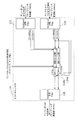
- FIG. 2 is a block diagram illustrating an example of a detailed functional configuration of the echo canceller 130 according to the first embodiment.
- the input signal to the echo canceller 130 includes a PCM signal (reference signal (ie, output audio signal)) from the decoder 120, a PCM signal (input audio signal) from the microphone 102, and a control signal from the controller 112. It is.
- the output signal (transmission audio signal) from the echo canceller 130 is a PCM signal to the encoder 140.
- the sampling frequency of the reference signal is 24 kHz (reproduction band is 12 kHz)
- the sampling frequency of the signal from the microphone 102 is 24 kHz (reproduction band is 12 kHz)
- the sampling frequency of the signal to the encoder 140 is 24 kHz.
- the echo canceller 130 includes subband division filters 131 and 132, pseudo echo generation units 133a to 133f, subtractors 134a to 134f, and a subband synthesis filter 135.
- the subband division filter 131 divides the PCM signal (output audio signal) input from the decoder 120 into a plurality of bands (a plurality of subbands) and downsamples the PCM signal.
- the band-divided signal is output to the pseudo echo generators 133a to 133f for each frequency band (for each subband).
- the sub-band division filter 132 divides the PCM signal (input audio signal) input from the microphone 102 into a plurality of bands (a plurality of sub-bands) and down-samples.
- the band-divided signal is output to the pseudo echo generators 133a to 133f for each frequency band (for each subband).
- the number of band divisions of the subband division filter 132 and the thinning rate in downsampling are preferably equal to the number of band divisions of the subband division filter 131 and the thinning rate.
- FIG. 2 shows an example of band division into six subbands as an example, it is not limited to this.
- 16-band division or 32-band division may be used.
- the thinning rate in downsampling may be any thinning rate as long as it is the same as or smaller than the number of band divisions.
- 10 subband division 1/10 downsampling (10 decimation) or 1/8 downsampling (8 decimation) may be used.
- the pseudo echo generators 133a to 133f use the input signal from the microphone 102 and the reference signal from the decoder 120 to estimate the transfer function of the space in which the audible signal output from the speaker 101 propagates, and the transfer function Is constituted by an adaptive filter having a predetermined number of taps, and a pseudo echo is generated by driving the adaptive filter.
- the pseudo echo generators 133a to 133f configure adaptive filters for the subband signals assigned to the pseudo echo generators 133a to 133f, and generate pseudo echoes.
- any method already known in the present embodiment may be used (for example, the method described in Non-Patent Document 2 may be used).
- the pseudo echo generators 133a to 133f set the number of filter taps for each subband based on the control signal from the controller 112. A specific operation based on a control signal from the controller 112 will be described later.
- the subtracters 134a to 134f reduce the echoes by subtracting the pseudo echoes generated by the pseudo echo generation units 133a to 133f from the input signal from the microphone 102.
- the subband synthesis filter 135 band-synthesizes the signal for each subband from which echo is removed as described above, and generates a time-speech transmission audio signal.
- the controller 112 controls the echo cancellation processing performance by the echo canceller 130 based on the reproduction band of the output audio signal, that is, the reproduction band of the audio signal encoded at the far end (other communication terminal).
- FIG. 3 is a diagram illustrating an example of a functional configuration of the echo canceller 130 when the sampling frequency of the output audio signal input from the decoder 120 is 8 kHz and the sampling frequency of the transmission audio signal output to the encoder 140 is 24 kHz. .
- the far-end encoder is, for example, G. 711, and occurs when the determination unit 111 determines that the far-end decoder is in the 24 kHz mode of AMR-WB, for example.
- the controller 112 controls the echo canceller 130 to process a subband signal in a band from 0 to 12 kHz. .
- the input audio signal is band-divided into six subbands by the subband division filter 132.
- the sampling frequency of the output audio signal (reference signal) from the decoder 120 is 8 kHz, that is, the reproduction band of the output audio signal is up to 4 kHz, among the input audio signals input from the microphone 102.
- the frequency band of the echoes included in is also 4 kHz or less. Therefore, only two subbands (0 to 2 kHz and 2 to 4 kHz) need to be subjected to echo cancellation processing.
- the controller 112 performs control so as not to perform echo cancellation processing in a subband higher than 4 kHz. That is, the controller 112 sets the number of filter taps of the pseudo echo generators 133c to 133f that process subbands of frequency components higher than 4 kHz to 0. Alternatively, the controller 112 may set the number of taps to a sufficiently small value so that the calculation amount can be ignored.
- the controller 112 sets the number of taps of the high frequency echo cancellation filter to the number of taps of the low frequency echo cancellation filter. You may set smaller than a number. That is, in this embodiment, since the echo cancellation processing is performed in the two low-frequency subbands, the controller 112 determines the number of taps of the filter in the 0 to 2 kHz band applied by the pseudo echo generation unit 133a as the pseudo echo generation. It may be set larger than the number of taps of the 2 to 4 kHz band filter applied by the unit 133b.
- the controller 112 causes the echo cancellation process to be executed only for the reproduction band of the output audio signal, that is, the subband including the frequency band equal to or less than the reproduction band of the audio signal encoded on the far end side.
- the controller 112 sets the number of filter taps to be applied to 0 in at least one subband including a frequency band equal to or higher than the reproduction band of the output audio signal.
- the number of filter taps to be applied is set to 0 in all subbands including a frequency band equal to or higher than the reproduction band of the output audio signal.
- the frequency band of the signal transmitted to the far end side is not impaired, and the echo cancellation processing can be performed only in the necessary minimum band, so that the communication terminal with a low calculation amount and high sound quality can be performed. And a communication method can be provided.
- FIG. 4 shows that the sampling frequency of the output audio signal (the signal encoded at the far end) input from the decoder 120 is 24 kHz, and the sampling frequency of the transmission audio signal (the signal decoded at the far end) output to the encoder 140. It is a figure which shows an example of a function structure of the echo canceller 130 when is 8 kHz.
- the reproduction band of the output audio signal is 12 kHz
- the frequency band of the echo included in the input audio signal input from the microphone 102 is also included in 12 kHz or less.
- the echo cancellation processing may be a band of 4 kHz or less. That is, the controller 112 sets the number of filter taps of the pseudo echo generators 133c to 133f that process subbands of frequency components higher than 4 kHz to 0 (or a sufficiently small value).
- the above is the same as that shown in FIG. 3, except that the input to the subband synthesis filter 135 is only an echo-cancelled signal. This is because the high frequency component cannot be reproduced on the far end side, and it is meaningless to band-synthesize the high frequency component.
- the control unit 110 causes the echo cancellation process to be performed only on the subband including the frequency below the reproduction band of the transmission audio signal, that is, the reproduction band of the audio signal decoded on the far end side.
- the control unit 110 sets the number of filter taps to be applied to 0 in at least one subband including a frequency band equal to or higher than the reproduction band of the transmission audio signal.
- control unit 110 sets the number of filter taps to be applied to 0 in all subbands including a frequency band equal to or higher than the reproduction band of the transmission audio signal.
- control unit 110 compares the reproduction band of the output audio signal and the reproduction band of the transmission audio signal, and determines whether to perform the echo cancellation processing based on the smaller reproduction band. Also good.
- the input audio signal does not include echoes in the frequency band above the playback band of the output audio signal. It is sufficient to perform the echo cancellation processing only on the subband including the band. Also, if the transmission band of the transmission audio signal is smaller than the reproduction band of the output audio signal, even if echo cancellation processing is performed in a frequency band that is higher than the reproduction band of the transmission audio signal, it is not transmitted to the far end side. It does not make sense, and it is sufficient to perform echo cancellation processing only on subbands including a frequency band equal to or lower than the reproduction band of the transmission audio signal.
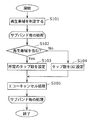
- FIG. 5 is a flowchart illustrating an example of echo cancellation processing according to the first embodiment.
- the determiner 111 determines the reproduction band of the output audio signal and the transmission audio signal (S101). Specifically, as described above, the determiner 111 determines the reproduction band by acquiring the codec type and sampling frequency of the encoder and decoder used at the far end (other communication terminals).
- controller 112 and the echo canceller 130 repeat the following processing for each subband.
- the controller 112 and the echo canceller 130 execute in order from the low-frequency subband.
- the controller 112 determines whether or not the subband includes the reproduction band (S102). For example, when the subband includes the reproduction band, such as the 0 to 2 kHz subband shown in FIG. 3 or FIG. 4 (Yes in S102), the controller 112 sets the echo canceller to set a predetermined number of taps. 130 is controlled (S103). At this time, the predetermined number of taps may be a predetermined fixed value.
- the controller 112 sets the echo canceller to set the number of taps to zero. 130 is controlled (S104).
- the echo canceller 130 executes an echo cancellation process by applying a filter with the set number of taps to the input audio signal subjected to the band division (S105).
- processing for each subband may be executed sequentially as in the flowchart shown in FIG. 5 or may be executed in parallel processing.
- the communication terminal 100 according to Embodiment 1 can reduce the amount of processing by controlling the handling of subband signals according to the processing capability on the far end side. Specifically, the communication terminal 100 according to Embodiment 1 determines the reproduction band of the audio signal processed by the other communication terminal from the type or sampling frequency of the codec used by the other communication terminal, and performs the reproduction. By controlling the echo cancellation processing performance based on the band, the amount of computation required for the echo cancellation processing can be reduced.
- the reproduction band is specified as a sampling frequency that can be directly specified from the type of codec determined by the determiner 111 or a sampling frequency of a signal at the time of encoding, and 1 / of the sampling frequency.
- the playback band was specified as 2.
- the reproduction band may not be accurately determined from the sampling frequency, but may be accurately determined by parameters included in the input bitstream.
- FIG. 6 is a block diagram showing another example of the configuration of the communication terminal according to the first embodiment.
- the communication terminal 200 shown in FIG. 6 is different from the communication terminal 100 shown in FIG. 1 in that a control unit 210 is provided instead of the control unit 110 and a decoder 220 is provided instead of the decoder 120.
- the control unit 210 is different in that the controller 212 is provided instead of the controller 112 and the determination unit 111 is not provided.
- description of the same points as in FIG. 1 will be omitted, and different points will be mainly described.
- the decoder 220 is an example of a decoding unit according to the present invention, and generates an output audio signal and a parameter by decoding an input bitstream including a parameter indicating a reproduction band of the output audio signal.
- an input bit stream encoded by the AAC method includes a parameter “max_sfb” indicating the upper limit of the reproduction band. Therefore, the decoder 220 outputs the parameter “max_sfb” to the controller 212 by decoding the input bit stream.
- the controller 212 acquires the parameter “max_sfb” from the decoder 220 and determines that the value indicated by the acquired “max_sfb” is the upper limit of the reproduction band. Then, the controller 212 controls the echo canceller 130 according to the determined reproduction band. The control of the echo canceller 130 at this time is the same as the operation performed by the controller 112 shown in FIG.
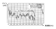
- FIG. 7 is a diagram showing an example of the frequency characteristic of the output audio signal. As shown in FIG. 7, the relationship between the reproduction band (Nyquist frequency) obtained from the sampling frequency and the reproduction band obtained from “max_sfb” is shown.
- the reproduction band obtained from the sampling frequency is 12 kHz
- the reproduction band obtained from “max_sfb” is 9 kHz. Therefore, since the echo is not included in the 9 to 12 kHz band of the input audio signal input from the microphone 102, the controller 212 sets the number of filter taps of the pseudo echo generation unit 133f shown in FIG.
- the amount of computation required for the echo cancellation process is reduced by setting the number of filter taps applied by the controller 112 or 212 when generating the pseudo echo to, for example, 0.
- the echo canceller 230 according to the modification of the first embodiment may have a function of switching whether or not to perform the echo cancellation processing for each subband.
- FIG. 8 is a diagram illustrating another example of a detailed functional configuration of the echo canceller 130 according to the first embodiment.
- the echo canceller 230 is different from the echo canceller 130 shown in FIG. 2 in that it newly includes switches 136a to 136f. In the following, description of the same points as in FIG. 2 will be omitted, and different points will be mainly described.
- the switches 136a to 136f are connected between the subband division filter 132 and each of the pseudo echo generation units 133a to 133f, respectively. Is switched based on a control signal (not shown) from the controller 112. That is, the switches 136a to 136f switch whether to execute the echo cancellation process for each subband.
- the controller 112 sets the control signal so as to turn on only the switch connected to the pseudo echo generation unit that processes the subband including the frequency band equal to or lower than the reproduction band of the output audio signal or the transmission audio signal. Output. That is, in the example shown in FIG. 3 or FIG. 4, the controller 112 turns on only the switches 136a and 136b and turns off the switches 136c to 136f.
- the echo canceller 230 according to the modification according to the first embodiment can perform the minimum necessary echo cancellation processing, the amount of calculation required for the echo cancellation processing can be reduced.
- the echo canceller 130 uses a technique for estimating the sound transmission characteristics between the speaker 101 and the microphone 102 by using an adaptive filter.
- the estimation of the transfer function by the adaptive filter cannot catch up and the echo cannot be removed as intended, or in the worst case, the howling phenomenon occurs. It is thought that it occurs.
- a videophone terminal that simultaneously transmit and receive not only audio signals but also video signals.
- a videophone terminal or the like it may be configured as a module in which a video camera and an audio microphone are integrated. In this case, it is possible to estimate whether or not the module is moving by analyzing the signal received by the video camera.
- the module itself is moving, that is, the positional relationship between the microphone 102 and the speaker 101 is changing. It is expected that In such a case, the echo cannot be removed, and howling may occur in the worst case. Therefore, the voice communication itself may be controlled to be stopped.
- FIG. 9 is a block diagram showing another example of the configuration of the communication terminal 100 according to the first embodiment.
- the microphone 102 constitutes a module 304 together with the camera 303.
- 9 is different from the communication terminal 100 shown in FIG. 1 in that a control unit 310 is provided instead of the control unit 110.
- the control unit 310 is different in that the determination unit 311 is provided instead of the determination unit 111.
- description of the same points as in FIG. 1 will be omitted, and different points will be mainly described.
- the determiner 311 acquires the video signal itself from the video camera 303 or information obtained from the signal from the camera 303, and the module 304 including the camera 303 and the microphone 102 is moving from the signal or information. It is determined whether or not. For example, if the determination unit 311 determines that the entire image is moving by performing motion detection processing on the transmitted video signal, it determines that the module 304 is moving.
- the determiner 311 performs control so as to stop the voice communication. For example, the determiner 311 stops the encoding process by the encoder 140 and the echo cancellation process by the echo canceller 130.
- the communication terminal 300 determines whether the module 304 in which the microphone 102 and the camera 303 are integrated is moving based on the video signal from the camera 303. Determine and stop inappropriate voice communication based on the determination result. For this reason, it is possible to prevent transmission of an audio signal in which echo cancellation has not been performed correctly or a signal in which howling has occurred to the far end side.
- the microphone 102 may include a sensor such as an acceleration sensor to detect movement, and the determiner 311 may stop voice communication based on information from the sensor.
- the codec type, the sampling frequency, the number of band divisions, and the downsampling rate are only examples, and these may be any values.
- the communication terminal according to Embodiment 2 is a communication terminal that communicates audio signals with other communication terminals, acquires an input audio signal collected by a microphone, and is included in the acquired input audio signal The echo component corresponding to the output audio signal output from the speaker is removed for each subband, and the echo cancellation unit that generates the audio signal for transmission and the amount of calculation by the processing executed by the communication terminal And a control unit for controlling the echo cancellation processing performance.
- FIG. 10 is a block diagram showing an example of the configuration of the communication terminal 400 according to the second embodiment.
- a communication terminal 400 shown in FIG. 10 is different from the communication terminal 100 shown in FIG. 1 in that a control unit 410 is provided instead of the control unit 110.
- description of the same points as in FIG. 1 will be omitted, and different points will be mainly described.
- the control unit 410 controls the echo cancellation processing performance by the echo canceller 130 for each subband in accordance with the amount of computation by the processing executed by the communication terminal 400. As shown in FIG. 10, the control unit 410 includes a determiner 411 and a controller 412.
- the determiner 411 determines whether or not the amount of calculation by the process executed by the communication terminal 400 exceeds a predetermined threshold. Specifically, the determiner 411 acquires processor calculation load information indicating the state of the processor calculation load, and determines whether the calculation amount of the processor exceeds a predetermined threshold based on the acquired processor calculation load information. To do.
- the processor is an arithmetic unit that actually processes each process performed by the communication terminal 400. Specifically, the processor executes the processes of the decoder 120, the echo canceller 130, the encoder 140, the determiner 411, and the controller 412.
- Processor calculation load information is information indicating the load state of functions being processed simultaneously by the processor, for example.
- the communication terminal 400 is a so-called videophone terminal that simultaneously transmits and receives a video signal, for example, a usage state (function of the function) of performing communication by a videophone system on a sub-screen while watching a TV broadcast on the main screen. Congested state).
- the calculation load on the processor increases, and as a result, the calculation amount allocated to the echo canceller 130 and the encoder 140 is compressed. In such a case, the amount of calculation is reduced by selecting a codec with a low calculation load among the codecs that can be processed on the far end side.
- the predetermined threshold value may be a predetermined fixed value. Alternatively, it may be dynamically determined according to the amount of computation of other processing required by the processor.
- the determiner 411 determines the audio signal by determining the type and / or sampling frequency of the codec that other communication terminals use when encoding or decoding.
- the playback band may be determined.
- the controller 412 controls the echo cancellation processing performance by the echo canceller 130 for each subband according to the amount of calculation by the processing executed by the communication terminal 400. Specifically, the controller 412 controls the echo cancellation processing performance when the determination unit 411 determines that the calculation amount exceeds a predetermined threshold. Specific operation of the controller 412 will be described later.
- the controller 412 controls the reproduction band of a transmission audio signal to be transmitted to another communication terminal because the calculation amount of the processor increases and exceeds a predetermined threshold.
- the sampling frequency of the PCM signal (output audio signal) from the decoder 120 and the sampling frequency of the PCM signal (input audio signal) from the microphone 102 are both 24 kHz (reproduction band is 12 kHz).
- 2 is a diagram illustrating an example of a functional configuration of an echo canceller 130.
- the determination unit 411 determines that the decoding method that can be processed on the far end side (another communication terminal) is the sampling frequency mode of 8 kHz to 24 kHz of AAC.
- the sampling frequency of both the PCM signal from the decoder 120 and the PCM signal from the microphone 102 is 24 kHz
- high-quality communication may be performed using the AAC 24 kHz sampling frequency mode.
- the controller 412 controls the echo canceller 130 to use the AAC 16 kHz sampling frequency mode.
- the controller 412 instructs the echo canceller 130 on the subband and the number of taps to perform echo cancellation processing when the determination unit 411 determines that the amount of computation of the processor exceeds a predetermined threshold.
- the sampling frequency is 16 kHz (that is, the reproduction band is 8 kHz)
- the number of taps sufficiently necessary for removing the echo is used as the number of taps of the filters of the pseudo echo generators 133a to 133d.
- the number of filter taps of the pseudo echo generators 133e and 133f is set to zero.
- control unit 410 reduces the reproduction band of the audio signal for transmission to be transmitted to other communication terminals when the amount of computation of the processor exceeds a predetermined threshold. Accordingly, control unit 410 sets the number of filter taps applied to the subbands that are no longer transmitted to 0 (or a sufficiently small value).
- the number of taps of the filters applied to each subband (the filters of the pseudo echo generation units 133a to 133d) is all equal has been described, but the number of filter taps may be different for each subband. .
- the low-band sub-band signal has a large influence on the echo, so a long tap length is maintained.
- the high-band signal has a small influence on the echo.
- the processing may be reduced by shortening the tap length.
- the size of the shaded area in the pseudo echo generator for each subband indicates the number of taps of the filter.
- control unit 410 may set the number of taps in advance so that the number of taps becomes larger or equal in the lower subbands regardless of the amount of calculation. At this time, the control unit 410 may change the number of taps when the calculation amount exceeds a predetermined threshold value or according to the reproduction band of the output audio signal or the transmission audio signal.
- the controller 412 keeps the magnitude relationship of the number of taps for each subband before and after the change, and the controller 412 reduces the number of taps for each subband so that the number of taps becomes small. May be set. In other words, the number of taps may be set so that the number of filter taps applied to the low-frequency subband is greater than the number of filter taps applied to the high-frequency subband before and after the change.
- the frequency processed by the encoder 140 or the number of taps of the echo canceller 130 is changed.
- the far end side (other communication terminals)
- the far end side Will affect the sound quality of the audio sent.
- a method of limiting the playback band of the playback sound on the near end side may be used.
- FIG. 13 is a block diagram showing another example of the configuration of the communication terminal according to the second embodiment.
- a communication terminal 500 shown in FIG. 13 is different from the communication terminal 400 of FIG. 10 in that a control unit 510 is provided instead of the control unit 410 and a band limiter 560 is newly provided.
- the controller 510 is different in that a controller 512 is provided instead of the controller 412.
- description of the same points as in FIG. 10 will be omitted, and different points will be mainly described.
- the band limiter 560 is an example of a band limiting unit according to the present invention, and outputs an output audio signal in the limited reproduction band to the speaker 101 by limiting the reproduction band of the output audio signal.
- the band limiter 560 may attenuate a high-frequency signal with a low-pass filter based on control from the controller 512, or may decrease the sampling frequency itself with a down-sampler.
- the controller 512 determines a reproduction band to be limited by the band limiter 560 when the calculation amount of the processor exceeds a predetermined threshold, and controls the echo cancellation processing performance according to the determined reproduction band.
- the specific control of the echo cancellation processing performance is the same as that of the controller 112 described above.
- FIG. 14 is a diagram illustrating an example of a functional configuration of the echo canceller 130 when the band is limited to 8 kHz.
- the band input to the subband synthesis filter 135 is limited to 0 to 8 kHz in FIG. 11, whereas in FIG. 14, the signal in a wider band (0 to 12 kHz) Is entered. Further, in both FIG. 14 and FIG. 11, the pseudo echo generation processing is not performed on the high frequency signal (8 to 12 kHz).
- the reproduction band of the output audio signal output from the speaker 101 is limited by the band limiter 560, so that it is known that there is no high-frequency component in the echo that wraps around in space. By doing so, the frequency band of the voice transmitted to the far end is maintained at a high band, so that it is possible to provide a good voice to the far end viewer, and at the communication terminal 600 The calculation amount of the echo cancellation process can be reduced.
- the band limiter 560 is provided as a method for limiting the reproduction band of the output audio signal.
- the decoder 120 decodes the input bitstream, the high band may be discarded. . That is, the decoder 120 may decode only the low band of the input bitstream.
- a communication terminal 600 shown in FIG. 15 is different from the communication terminal 400 shown in FIG. 10 in that it includes a control unit 510 instead of the control unit 410 and a new instruction unit 670. In the following, description of the same points as in FIG. 10 will be omitted, and different points will be mainly described.
- the instruction unit 670 gives an instruction to limit the reproduction band of the audio signal used when another communication terminal generates the input bit stream when the calculation amount of the processor exceeds a predetermined threshold. Send to. Specifically, instructing unit 670 transmits an instruction for setting the reproduction band determined by control unit 510 to the reproduction band used by the encoders of other communication terminals.
- the frequency band of the voice transmitted from the communication terminal 600 to the other communication terminal is maintained as a high band, it is possible to provide good voice to the viewer on the other communication terminal side, The amount of computation of echo cancellation processing in the communication terminal 600 can be reduced.
- the processor calculation load information may be information indicating the reverberation characteristics in the room where the speaker 101 and the microphone 102 are arranged, for example. Or the information which shows the reverberation characteristic assumed in the room where the speaker 101 and the microphone 102 are arrange
- positioned may be sufficient.
- the communication terminal 400 according to Embodiment 2 obtains information indicating the reverberation characteristic in the room by generating an impulse sound from the speaker 101 and measuring the reverberation characteristic with respect to the impulse sound.
- the tap length for generating the pseudo echo must be long, but this imposes pressure on the amount of computation given to the codec.
- a codec with a low sampling frequency among the codecs that can be processed on the far end side not only can the amount of calculation of encoding be reduced, but also the number of bands and taps of the echo canceller can be reduced. it can.
- the reverberation characteristic when the reverberation characteristic is short, it is considered that there are few echo components included in the input audio signal, so the number of filter taps and the number of subbands for executing echo cancellation may be reduced.
- the control of the echo canceller 130 described above or the output audio is based only on the calculation amount of the processor of the communication terminal 400 according to the second embodiment.
- Band limitation of the signal or the audio signal for transmission may be performed.
- the control unit 410 performs echo cancellation processing only on one or more subbands including a subband including the minimum frequency band and not including the maximum frequency band. May be executed.
- the control unit 410 may set the number of filter taps applied to one or more subbands including a subband including the maximum frequency band and not including the minimum frequency band to zero.
- the echo cancellation processing is performed on at least the subband including the minimum frequency band. This is because it is desirable.
- the present invention may be realized not only as a communication terminal and a communication method, but also as a program for causing a computer to execute the communication method of the present embodiment. Further, it may be realized as a computer-readable recording medium such as a CD-ROM for recording the program. Furthermore, it may be realized as information, data, or a signal indicating the program. These programs, information, data, and signals may be distributed via a communication network such as the Internet.
- the constituent elements constituting the communication terminal may be constituted by one system LSI.
- the system LSI is an ultra-multifunctional LSI manufactured by integrating a plurality of components on a single chip.
- the system LSI is a computer system including a microprocessor, a ROM, a RAM, and the like. .
- the communication terminal and the communication method according to the present invention can reduce the amount of computation required for echo cancellation, and can be used for various communication devices such as a TV phone or a TV conference communication terminal. it can.
Landscapes
- Engineering & Computer Science (AREA)
- Signal Processing (AREA)
- Computer Networks & Wireless Communication (AREA)
- Telephone Function (AREA)
- Cable Transmission Systems, Equalization Of Radio And Reduction Of Echo (AREA)
Abstract
L'invention concerne un terminal de communication (100) qui communique un signal audio et qui est pourvu : d'un décodeur (120) qui génère un signal audio de sortie par le décodage d'un flux de bits d'entrée reçu d'un autre terminal de communication et qui émet en sortie le signal audio de sortie généré vers un haut-parleur ; d'un dispositif d'annulation d'écho (130) qui acquiert un signal audio d'entrée acquis à l'aide d'un microphone (102) installé dans l'espace dans lequel le haut-parleur (101) émet du son et, sur chaque sous-bande, qui élimine les composantes d'écho qui sont incluses dans le signal audio acquis et qui correspondent au signal audio d'entrée, générant ainsi un signal audio d'émission ; d'un codeur (140) qui génère un flux de bits de sortie par le codage du signal audio d'émission et qui émet le flux de bis de sortie ainsi généré vers un autre terminal de communication, et une unité de commande (110) qui commande le fonctionnement du traitement d'annulation d'écho pour chaque sous-bande selon une bande de reproduction d'au moins un signal parmi le signal audio de sortie et le signal audio d'émission.
Priority Applications (2)
| Application Number | Priority Date | Filing Date | Title |
|---|---|---|---|
| CN201180010497.XA CN102763343B (zh) | 2010-02-24 | 2011-01-26 | 通信终端 |
| US13/590,243 US8694326B2 (en) | 2010-02-24 | 2012-08-21 | Communication terminal and communication method |
Applications Claiming Priority (2)
| Application Number | Priority Date | Filing Date | Title |
|---|---|---|---|
| JP2010039337A JP5424936B2 (ja) | 2010-02-24 | 2010-02-24 | 通信端末及び通信方法 |
| JP2010-039337 | 2010-02-24 |
Related Child Applications (1)
| Application Number | Title | Priority Date | Filing Date |
|---|---|---|---|
| US13/590,243 Continuation US8694326B2 (en) | 2010-02-24 | 2012-08-21 | Communication terminal and communication method |
Publications (1)
| Publication Number | Publication Date |
|---|---|
| WO2011105006A1 true WO2011105006A1 (fr) | 2011-09-01 |
Family
ID=44506441
Family Applications (1)
| Application Number | Title | Priority Date | Filing Date |
|---|---|---|---|
| PCT/JP2011/000398 Ceased WO2011105006A1 (fr) | 2010-02-24 | 2011-01-26 | Terminal et procédé de communication |
Country Status (4)
| Country | Link |
|---|---|
| US (1) | US8694326B2 (fr) |
| JP (1) | JP5424936B2 (fr) |
| CN (1) | CN102763343B (fr) |
| WO (1) | WO2011105006A1 (fr) |
Cited By (2)
| Publication number | Priority date | Publication date | Assignee | Title |
|---|---|---|---|---|
| CN102780511A (zh) * | 2012-07-30 | 2012-11-14 | 华为技术有限公司 | 回声抵消器、数据传输系统和回声抵消的方法 |
| CN103730125A (zh) * | 2012-10-12 | 2014-04-16 | 华为技术有限公司 | 一种回声抵消方法和设备 |
Families Citing this family (12)
| Publication number | Priority date | Publication date | Assignee | Title |
|---|---|---|---|---|
| JP2013207465A (ja) * | 2012-03-28 | 2013-10-07 | Brother Ind Ltd | 会議システム、端末装置および会議方法 |
| JP2014074782A (ja) * | 2012-10-03 | 2014-04-24 | Sony Corp | 音声送信装置、音声送信方法、音声受信装置および音声受信方法 |
| US9697847B2 (en) * | 2013-03-14 | 2017-07-04 | Semiconductor Components Industries, Llc | Acoustic signal processing system capable of detecting double-talk and method |
| KR102244612B1 (ko) | 2014-04-21 | 2021-04-26 | 삼성전자주식회사 | 무선 통신 시스템에서 음성 데이터를 송신 및 수신하기 위한 장치 및 방법 |
| CN107005268B (zh) * | 2014-12-15 | 2020-06-16 | 三菱电机株式会社 | 回波消除装置和回波消除方法 |
| US9847093B2 (en) | 2015-06-19 | 2017-12-19 | Samsung Electronics Co., Ltd. | Method and apparatus for processing speech signal |
| US10504530B2 (en) | 2015-11-03 | 2019-12-10 | Dolby Laboratories Licensing Corporation | Switching between transforms |
| GB2545263B (en) * | 2015-12-11 | 2019-05-15 | Acano Uk Ltd | Joint acoustic echo control and adaptive array processing |
| JP6977772B2 (ja) | 2017-07-07 | 2021-12-08 | ヤマハ株式会社 | 音声処理方法、音声処理装置、ヘッドセット、および、遠隔会話システム |
| US10692515B2 (en) * | 2018-04-17 | 2020-06-23 | Fortemedia, Inc. | Devices for acoustic echo cancellation and methods thereof |
| JP7622391B2 (ja) * | 2020-10-02 | 2025-01-28 | ヤマハ株式会社 | 音響処理方法および音響処理システム |
| FR3145849A1 (fr) * | 2023-02-13 | 2024-08-16 | Orange | Procédé de supervision d’un terminal de lecture de flux multimédia avec temporisation de la transmission des données de suivi |
Citations (8)
| Publication number | Priority date | Publication date | Assignee | Title |
|---|---|---|---|---|
| JPH06318885A (ja) * | 1993-03-11 | 1994-11-15 | Nec Corp | 帯域分割適応フィルタによる未知システム同定の方法及び装置 |
| JPH07123028A (ja) * | 1993-10-25 | 1995-05-12 | Ricoh Co Ltd | 音声会議装置 |
| JPH0879137A (ja) * | 1994-09-01 | 1996-03-22 | Nec Corp | 帯域分割適応フィルタによる未知システム同定の方法及び装置 |
| JPH11355182A (ja) * | 1998-06-11 | 1999-12-24 | Nec Corp | 帯域分割適応フィルタによる未知システム同定方法及び装置 |
| JP2001044896A (ja) * | 1999-08-03 | 2001-02-16 | Matsushita Electric Ind Co Ltd | 通話装置および通話方法 |
| JP2005175804A (ja) * | 2003-12-10 | 2005-06-30 | Sony Corp | エコーキャンセラ |
| JP2005333550A (ja) * | 2004-05-21 | 2005-12-02 | Oki Electric Ind Co Ltd | 音声通信システムおよびその電話機 |
| JP2006333062A (ja) * | 2005-05-26 | 2006-12-07 | Nippon Telegr & Teleph Corp <Ntt> | ハウリング防止方法、その装置、そのプログラムおよびその記録媒体 |
Family Cites Families (18)
| Publication number | Priority date | Publication date | Assignee | Title |
|---|---|---|---|---|
| FI100840B (fi) * | 1995-12-12 | 1998-02-27 | Nokia Mobile Phones Ltd | Kohinanvaimennin ja menetelmä taustakohinan vaimentamiseksi kohinaises ta puheesta sekä matkaviestin |
| US5995923A (en) * | 1997-06-26 | 1999-11-30 | Nortel Networks Corporation | Method and apparatus for improving the voice quality of tandemed vocoders |
| EP0947068A2 (fr) * | 1997-09-10 | 1999-10-06 | Cellon France SAS | Systeme de communication et terminal |
| EP1006672A3 (fr) | 1998-11-30 | 2005-02-02 | Infineon Technologies North America Corp. | Annuleur d'échos integré et codeur/décodeur de compression programmable |
| US6597732B1 (en) * | 1999-01-14 | 2003-07-22 | Eric Morgan Dowling | High-speed modem with uplink remote-echo canceller |
| US7003093B2 (en) * | 2000-09-08 | 2006-02-21 | Intel Corporation | Tone detection for integrated telecommunications processing |
| US20030028386A1 (en) * | 2001-04-02 | 2003-02-06 | Zinser Richard L. | Compressed domain universal transcoder |
| JP4231698B2 (ja) * | 2001-05-10 | 2009-03-04 | ポリコム イスラエル リミテッド | 多地点マルチメディア/音声システムの制御ユニット |
| US6928495B2 (en) * | 2002-09-27 | 2005-08-09 | Broadcom Corporation | Method and system for an adaptive multimode media queue |
| DE102004024823B4 (de) * | 2004-05-19 | 2009-09-17 | Infineon Technologies Ag | Verfahren zur Verringerung eines Rechenaufwands in nichtlinearen Filteranordnungen sowie entsprechende Filteranordnungen |
| NO322301B1 (no) * | 2005-07-13 | 2006-09-11 | Tandberg Telecom As | Fremgangsmate og system for ekkokansellering med liten forsinkelse. |
| WO2007058121A1 (fr) * | 2005-11-15 | 2007-05-24 | Nec Corporation | Dispositif et méthode de suppression de réverbération et programme de suppression de réverbération |
| US8433050B1 (en) * | 2006-02-06 | 2013-04-30 | Avaya Inc. | Optimizing conference quality with diverse codecs |
| US8184537B1 (en) * | 2006-02-10 | 2012-05-22 | Mindspeed Technologies, Inc. | Method and apparatus for quantifying, predicting and monitoring the conversational quality |
| US20080109217A1 (en) * | 2006-11-08 | 2008-05-08 | Nokia Corporation | Method, Apparatus and Computer Program Product for Controlling Voicing in Processed Speech |
| JP4569618B2 (ja) | 2006-11-10 | 2010-10-27 | ソニー株式会社 | エコーキャンセラ及び通話音声処理装置 |
| US8285554B2 (en) * | 2007-07-27 | 2012-10-09 | Dsp Group Limited | Method and system for dynamic aliasing suppression |
| US8301440B2 (en) * | 2008-05-09 | 2012-10-30 | Broadcom Corporation | Bit error concealment for audio coding systems |
-
2010
- 2010-02-24 JP JP2010039337A patent/JP5424936B2/ja not_active Expired - Fee Related
-
2011
- 2011-01-26 CN CN201180010497.XA patent/CN102763343B/zh not_active Expired - Fee Related
- 2011-01-26 WO PCT/JP2011/000398 patent/WO2011105006A1/fr not_active Ceased
-
2012
- 2012-08-21 US US13/590,243 patent/US8694326B2/en not_active Expired - Fee Related
Patent Citations (8)
| Publication number | Priority date | Publication date | Assignee | Title |
|---|---|---|---|---|
| JPH06318885A (ja) * | 1993-03-11 | 1994-11-15 | Nec Corp | 帯域分割適応フィルタによる未知システム同定の方法及び装置 |
| JPH07123028A (ja) * | 1993-10-25 | 1995-05-12 | Ricoh Co Ltd | 音声会議装置 |
| JPH0879137A (ja) * | 1994-09-01 | 1996-03-22 | Nec Corp | 帯域分割適応フィルタによる未知システム同定の方法及び装置 |
| JPH11355182A (ja) * | 1998-06-11 | 1999-12-24 | Nec Corp | 帯域分割適応フィルタによる未知システム同定方法及び装置 |
| JP2001044896A (ja) * | 1999-08-03 | 2001-02-16 | Matsushita Electric Ind Co Ltd | 通話装置および通話方法 |
| JP2005175804A (ja) * | 2003-12-10 | 2005-06-30 | Sony Corp | エコーキャンセラ |
| JP2005333550A (ja) * | 2004-05-21 | 2005-12-02 | Oki Electric Ind Co Ltd | 音声通信システムおよびその電話機 |
| JP2006333062A (ja) * | 2005-05-26 | 2006-12-07 | Nippon Telegr & Teleph Corp <Ntt> | ハウリング防止方法、その装置、そのプログラムおよびその記録媒体 |
Cited By (3)
| Publication number | Priority date | Publication date | Assignee | Title |
|---|---|---|---|---|
| CN102780511A (zh) * | 2012-07-30 | 2012-11-14 | 华为技术有限公司 | 回声抵消器、数据传输系统和回声抵消的方法 |
| CN103730125A (zh) * | 2012-10-12 | 2014-04-16 | 华为技术有限公司 | 一种回声抵消方法和设备 |
| EP2905778A4 (fr) * | 2012-10-12 | 2015-11-25 | Huawei Tech Co Ltd | Procédé et dispositif d'élimination d'écho |
Also Published As
| Publication number | Publication date |
|---|---|
| JP5424936B2 (ja) | 2014-02-26 |
| CN102763343A (zh) | 2012-10-31 |
| JP2011176638A (ja) | 2011-09-08 |
| CN102763343B (zh) | 2014-08-20 |
| US8694326B2 (en) | 2014-04-08 |
| US20120323583A1 (en) | 2012-12-20 |
Similar Documents
| Publication | Publication Date | Title |
|---|---|---|
| JP5424936B2 (ja) | 通信端末及び通信方法 | |
| CA2865533C (fr) | Procede et dispositif de traitement de signal de frequence vocale | |
| AU2009210295B9 (en) | Apparatus and method for computing filter coefficients for echo suppression | |
| US8073497B2 (en) | Echo canceller with correlation using pre-whitened data values received by downlink codec | |
| US20090046866A1 (en) | Apparatus capable of performing acoustic echo cancellation and a method thereof | |
| JP4386379B2 (ja) | 会議または電話用の音響エコー・キャンセラのバックグラウンド訓練 | |
| JP4241831B2 (ja) | エコー及び雑音の適応制御の為の方法及び装置 | |
| JP2007515911A (ja) | ステレオ音声を向上させるためのシステム及び方法 | |
| CN101313483A (zh) | 回音消除的配置 | |
| JP2001318694A (ja) | 信号処理装置、信号処理方法および記録媒体 | |
| KR20160076059A (ko) | 디스플레이장치 및 그 반향 제거방법 | |
| US9491306B2 (en) | Signal processing control in an audio device | |
| KR100842590B1 (ko) | 이동 단말에서 음향 반향 제거 방법 및 장치 | |
| CN108540680B (zh) | 讲话状态的切换方法及装置、通话系统 | |
| US8774398B2 (en) | Transceiver | |
| US7085245B2 (en) | Coefficient domain history storage of voice processing systems | |
| CN102655005B (zh) | 一种语音增强处理方法和装置 | |
| KR20010002001A (ko) | 지연시간추정을 이용한 잔향 제거장치 및 방법 | |
| EP2568619B1 (fr) | Codec d'annulation d'écho | |
| JP5480226B2 (ja) | 信号処理装置および信号処理方法 | |
| CN114333867A (zh) | 音频数据处理方法和装置、通话方法、音频处理芯片、电子设备以及计算机可读存储介质 | |
| JP2007151038A (ja) | 音声処理装置 | |
| JP2006121589A (ja) | エコー消去方法、この方法を実施する装置、プログラムおよびその記録媒体 | |
| JP2006121588A (ja) | エコー抑圧方法、この方法を実施する装置、プログラムおよびその記録媒体 | |
| JP2010158044A (ja) | 信号処理装置および信号処理方法 |
Legal Events
| Date | Code | Title | Description |
|---|---|---|---|
| WWE | Wipo information: entry into national phase |
Ref document number: 201180010497.X Country of ref document: CN |
|
| 121 | Ep: the epo has been informed by wipo that ep was designated in this application |
Ref document number: 11746979 Country of ref document: EP Kind code of ref document: A1 |
|
| NENP | Non-entry into the national phase |
Ref country code: DE |
|
| 122 | Ep: pct application non-entry in european phase |
Ref document number: 11746979 Country of ref document: EP Kind code of ref document: A1 |