WO2011105089A1 - 色素増感太陽電池の製造装置及び色素増感太陽電池の製造方法 - Google Patents
色素増感太陽電池の製造装置及び色素増感太陽電池の製造方法 Download PDFInfo
- Publication number
- WO2011105089A1 WO2011105089A1 PCT/JP2011/001069 JP2011001069W WO2011105089A1 WO 2011105089 A1 WO2011105089 A1 WO 2011105089A1 JP 2011001069 W JP2011001069 W JP 2011001069W WO 2011105089 A1 WO2011105089 A1 WO 2011105089A1
- Authority
- WO
- WIPO (PCT)
- Prior art keywords
- dye
- solar cell
- sensitized solar
- producing
- substrate
- Prior art date
- Legal status (The legal status is an assumption and is not a legal conclusion. Google has not performed a legal analysis and makes no representation as to the accuracy of the status listed.)
- Ceased
Links
Images



Classifications
-
- H—ELECTRICITY
- H01—ELECTRIC ELEMENTS
- H01G—CAPACITORS; CAPACITORS, RECTIFIERS, DETECTORS, SWITCHING DEVICES, LIGHT-SENSITIVE OR TEMPERATURE-SENSITIVE DEVICES OF THE ELECTROLYTIC TYPE
- H01G9/00—Electrolytic capacitors, rectifiers, detectors, switching devices, light-sensitive or temperature-sensitive devices; Processes of their manufacture
- H01G9/20—Light-sensitive devices
- H01G9/2068—Panels or arrays of photoelectrochemical cells, e.g. photovoltaic modules based on photoelectrochemical cells
-
- H—ELECTRICITY
- H10—SEMICONDUCTOR DEVICES; ELECTRIC SOLID-STATE DEVICES NOT OTHERWISE PROVIDED FOR
- H10F—INORGANIC SEMICONDUCTOR DEVICES SENSITIVE TO INFRARED RADIATION, LIGHT, ELECTROMAGNETIC RADIATION OF SHORTER WAVELENGTH OR CORPUSCULAR RADIATION
- H10F71/00—Manufacture or treatment of devices covered by this subclass
-
- H—ELECTRICITY
- H10—SEMICONDUCTOR DEVICES; ELECTRIC SOLID-STATE DEVICES NOT OTHERWISE PROVIDED FOR
- H10F—INORGANIC SEMICONDUCTOR DEVICES SENSITIVE TO INFRARED RADIATION, LIGHT, ELECTROMAGNETIC RADIATION OF SHORTER WAVELENGTH OR CORPUSCULAR RADIATION
- H10F19/00—Integrated devices, or assemblies of multiple devices, comprising at least one photovoltaic cell covered by group H10F10/00, e.g. photovoltaic modules
-
- H—ELECTRICITY
- H01—ELECTRIC ELEMENTS
- H01G—CAPACITORS; CAPACITORS, RECTIFIERS, DETECTORS, SWITCHING DEVICES, LIGHT-SENSITIVE OR TEMPERATURE-SENSITIVE DEVICES OF THE ELECTROLYTIC TYPE
- H01G9/00—Electrolytic capacitors, rectifiers, detectors, switching devices, light-sensitive or temperature-sensitive devices; Processes of their manufacture
- H01G9/20—Light-sensitive devices
- H01G9/2027—Light-sensitive devices comprising an oxide semiconductor electrode
- H01G9/2031—Light-sensitive devices comprising an oxide semiconductor electrode comprising titanium oxide, e.g. TiO2
-
- H—ELECTRICITY
- H01—ELECTRIC ELEMENTS
- H01G—CAPACITORS; CAPACITORS, RECTIFIERS, DETECTORS, SWITCHING DEVICES, LIGHT-SENSITIVE OR TEMPERATURE-SENSITIVE DEVICES OF THE ELECTROLYTIC TYPE
- H01G9/00—Electrolytic capacitors, rectifiers, detectors, switching devices, light-sensitive or temperature-sensitive devices; Processes of their manufacture
- H01G9/20—Light-sensitive devices
- H01G9/2059—Light-sensitive devices comprising an organic dye as the active light absorbing material, e.g. adsorbed on an electrode or dissolved in solution
-
- Y—GENERAL TAGGING OF NEW TECHNOLOGICAL DEVELOPMENTS; GENERAL TAGGING OF CROSS-SECTIONAL TECHNOLOGIES SPANNING OVER SEVERAL SECTIONS OF THE IPC; TECHNICAL SUBJECTS COVERED BY FORMER USPC CROSS-REFERENCE ART COLLECTIONS [XRACs] AND DIGESTS
- Y02—TECHNOLOGIES OR APPLICATIONS FOR MITIGATION OR ADAPTATION AGAINST CLIMATE CHANGE
- Y02E—REDUCTION OF GREENHOUSE GAS [GHG] EMISSIONS, RELATED TO ENERGY GENERATION, TRANSMISSION OR DISTRIBUTION
- Y02E10/00—Energy generation through renewable energy sources
- Y02E10/50—Photovoltaic [PV] energy
- Y02E10/542—Dye sensitized solar cells
-
- Y—GENERAL TAGGING OF NEW TECHNOLOGICAL DEVELOPMENTS; GENERAL TAGGING OF CROSS-SECTIONAL TECHNOLOGIES SPANNING OVER SEVERAL SECTIONS OF THE IPC; TECHNICAL SUBJECTS COVERED BY FORMER USPC CROSS-REFERENCE ART COLLECTIONS [XRACs] AND DIGESTS
- Y02—TECHNOLOGIES OR APPLICATIONS FOR MITIGATION OR ADAPTATION AGAINST CLIMATE CHANGE
- Y02P—CLIMATE CHANGE MITIGATION TECHNOLOGIES IN THE PRODUCTION OR PROCESSING OF GOODS
- Y02P70/00—Climate change mitigation technologies in the production process for final industrial or consumer products
- Y02P70/50—Manufacturing or production processes characterised by the final manufactured product
Definitions
- the present invention relates to a dye-sensitized solar cell manufacturing apparatus and a dye-sensitized solar cell manufacturing method.
- a dye-sensitized solar cell has been proposed as a solar cell that can be manufactured at a low cost under normal pressure and atmospheric atmosphere.
- a dye-sensitized solar cell with a general structure is a metal oxide composed of a thin film with transparent conductivity on one surface of a transparent substrate and fine particles with the dye adsorbed on the surface of the thin film with transparent conductivity.
- a metal complex system containing a metal such as Ru or an organic dye system containing no metal is used as the photosensitizing dye.
- the step for adsorbing the dye on the metal oxide porous semiconductor layer is performed by immersing in a dark solution at atmospheric pressure for about half a day in a solution in which the dye is dissolved. Therefore, in order to shorten the time required for manufacturing the dye-sensitized solar cell and to produce more efficiently, it is required to increase the speed of the dye adsorption process.
- a carbon dioxide supercritical fluid in which a Ru complex, which is one of metal complexes, is dissolved can be obtained as a dye solution.
- a method of immersing a substrate having a film made of porous metal oxide semiconductor fine particles in a pressurized fluid has been proposed. According to this method, there is a report that it is possible to obtain a higher photoelectric conversion efficiency than a film obtained by a conventional dipping method in a film adsorbed by dye by 30-minute dipping (see, for example, Patent Document 1). ).
- a dye composed of a Ru complex exhibits high photoelectric conversion efficiency, but it takes a long time for adsorption.
- a dye adsorption device composed of a large pressure vessel capable of withstanding a pressure close to 100 atm is required.
- this pressure resistance performance is added to a large cell production facility, the device becomes very expensive, which is contrary to low-cost production required for a dye-sensitized solar cell.
- the method and apparatus capable of adsorbing dyes in a short time without using a high pressure close to 100 atm. Improvement of the photoelectric conversion efficiency of the dye-sensitized solar cell manufactured in the system including it is desired.
- the present invention has been made in response to the above-described conventional circumstances, and is a dye-sensitized solar cell manufactured in a system including a high-speed and low-cost production process of a dye-sensitized solar cell and this dye adsorption process. It is an object of the present invention to provide a dye-sensitized solar cell manufacturing apparatus and a dye-sensitized solar cell manufacturing method capable of improving the photoelectric conversion efficiency.
- One embodiment of the dye-sensitized solar cell production apparatus of the present invention is a dye-sensitized method in which a photosensitizing dye solution is brought into contact with an electrode material layer that functions as a working electrode of a dye-sensitized solar cell to adsorb the photosensitizing dye.
- An apparatus for manufacturing a solar cell wherein the electrode material layer is stored in a hermetically sealed container-like substrate housing portion that houses a substrate, and passes through the surface of the substrate housed in the substrate housing portion.
- a circulation mechanism for circulating the photosensitizing dye solution, and the cross-sectional area of the flow path of the photosensitizing dye solution in the portion of the substrate housing portion facing the substrate is the photosensitizing portion in the other portion. It is characterized by being smaller than the cross-sectional area of the flow path of the dye solution.
- One aspect of the method for producing a dye-sensitized solar cell of the present invention is a dye-sensitized method in which a photosensitizing dye solution is brought into contact with an electrode material layer that functions as a working electrode of a dye-sensitized solar cell to adsorb the photosensitizing dye.
- a method for manufacturing a solar cell wherein the substrate on which the electrode material layer is formed is housed in a sealed container-like substrate housing portion, the surface of the substrate housed in the substrate housing portion, and the surface The photosensitizing dye solution is circulated through a bottleneck formed between the opposite surface of the substrate housing portion and the opposite surface.
- the production process of a dye-sensitized solar cell can be speeded up and reduced in cost, and the photoelectric conversion efficiency of a dye-sensitized solar cell manufactured in a system including this dye adsorption process can be improved.
- a dye-sensitized solar cell manufacturing apparatus and a dye-sensitized solar cell manufacturing method can be provided.
- the figure which shows the structure of the adsorption apparatus of the photosensitizing dye which concerns on one Embodiment of this invention The figure which shows the principal part structure of the adsorption apparatus of the photosensitizing dye of FIG.
- the figure which shows the principal part structure of the adsorption apparatus of the photosensitizing dye of FIG. The figure which shows the principal part structure of the adsorption apparatus of the photosensitizing dye of FIG.
- FIG. 1 schematically shows the entire configuration of a photosensitizing dye adsorption device 100 as a dye-sensitized solar cell manufacturing apparatus according to an embodiment of the present invention.
- This adsorbing device for photosensitizing dye 100 includes a substrate housing portion 2 for placing a substrate 1 on which an electrode material layer that functions as a working electrode of a dye-sensitized solar cell is formed.
- the substrate housing part 2 is formed in a sealed container shape.
- the substrate housing part 2 includes a pressure gauge 3 for measuring the pressure of the internal photosensitizing dye solution, and the temperature of the photosensitizing dye solution.
- a thermometer 4 for measurement is provided so that the pressure and temperature of the photosensitizing dye solution can be measured.
- a temperature control bath (not shown) is provided outside the substrate container 2 so that the temperature of the photosensitizing dye solution in the substrate container 2 can be adjusted.
- a circulation line 10 for circulating the photosensitizing dye solution is connected to the substrate container 2.
- a tank 11 for storing a photosensitizing dye solution, a pump 12, a flow meter 13, manual valves 14 and 15, a needle valve 16 and an inversion valve 31 are inserted.
- the circulation line 10 is provided with a bypass line 17 that branches from the upstream side of the substrate housing portion 2 and is connected to the downstream side of the substrate housing portion 2.
- the bypass line 17 includes manual valves 18 and 19. Is inserted.
- the bypass line 17 is for bypassing the substrate housing portion 2 to circulate the photosensitizing dye solution, and is used when the substrate 1 on which the electrode material layer is formed is arranged or taken out from the substrate housing portion 2. .
- the reverse valve 31 is for reversing the flow of the photosensitizing dye solution with respect to the substrate 1.
- the size of the substrate 1 is large, there is a possibility that the adsorption of the photosensitizing dye to the electrode material layer of the substrate 1 is different between the upstream side and the downstream side of the flow of the photosensitizing dye solution.
- a plurality of substrates 1 are disposed in the substrate accommodating portion 2 for processing, there is a possibility that a difference in adsorption of the photosensitizing dye occurs between the substrate 1 disposed on the upstream side and the substrate 1 disposed on the downstream side. There is. Therefore, the flow of the photosensitizing dye solution may be reversed by switching the flow path with the reversing valve 31 so that the photosensitizing dye is adsorbed uniformly.
- the tank 11 for storing the photosensitizing dye solution has a temperature control bath 20 for adjusting the temperature of the internal photosensitizing dye solution and a temperature for measuring the temperature of the photosensitizing dye solution in the tank 11. A total of 21 is provided. Then, the photosensitizing dye solution temperature-controlled by the temperature adjustment bath 20 is circulated to the substrate housing unit 2 by the pump 12. In the case where the temperature of the photosensitizing dye solution changes in the process in which the photosensitizing dye solution reaches the substrate housing portion 2 from the tank 11, the circulation line 10 is made of a highly heat insulating member or the circulation line 10. The bypass line 17 may be covered with a heat insulating member.
- photosensitizing dye solution a solution obtained by dissolving a photosensitizing dye in a solvent is used.
- Photosensitizing dyes include metal complex systems containing metals such as Ru and organic dye systems that do not contain metals. For Ru-based metal complexes, N3, N719, and black die are often used.
- organic dye system indoline, xanthene, coumarin, perylene, cyanine, merocyanine, polyene, porphyrin, and the like can be used.
- a solvent for dissolving the photosensitizing dye a common organic solvent such as water, alcohol, acetonitrile, ethanol, toluene, dimethylformamide, and tetrahydrofuran can be used.
- the concentration of the photosensitizing dye solution is desirably in the range of about 0.1 mM to 1 mM. If the concentration is low, the adsorption time increases, but if the concentration is too high, association between the photosensitizing dyes occurs on the fine particles adsorbed by the photosensitizing dye. This association is a factor that reduces the efficiency of photoelectric conversion. Moreover, the density
- FIG. 2 schematically shows a vertical cross-sectional configuration (FIG. 2A) and a horizontal cross-sectional configuration (FIG. 2B) of the substrate housing portion 2, and FIG. FIG. 2 is a perspective view schematically showing the configuration of FIG.
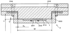
- a flow path 200 for circulating a photosensitizing dye solution formed in a rectangular cross section is formed in the substrate housing portion 2.
- a concave portion 201 is provided which is recessed in a rectangular shape according to the outer shape of the substrate 1 and on which the substrate 1 is placed.
- the recess 201 is provided with a suction mechanism 205 for fixing the substrate 1.
- a lid member 202 is provided on the ceiling of the flow path 200 facing the recess 201.
- a projecting portion 203 that projects in a rectangular shape in accordance with the shape of the flow path 200 is provided below the lid member 202.
- the photosensitizing dye solution flow path (bottle path) 210 formed between the protrusion 203 and the substrate 1 and facing the surface of the substrate 1 is narrower than the other parts, that is, the flow path.
- the cross-sectional area is reduced.
- the lid member 202 and the protruding portion 203 are detachable by removing a plurality of (four in this embodiment) screws 204, and are exchanged for the lid member 202 provided with the protruding portions 203 having different protruding amounts. By doing so, the cross-sectional area of the flow path 210 can be changed.
- the lid member 202 and the protruding portion 203 are preferably made of a material that does not transmit light, but in this embodiment, they are made of transparent acrylic. Thereby, the lid member 202 and the protruding portion 203 can be used as an observation window for observing the inside of the substrate housing portion 2. In this case, it is desirable to cover the lid 202 with a light shielding member when not observing.
- FIG. 4 shows an example of a cross-sectional configuration of the flow path 210 portion.
- the flow path width W is 90 mm
- the flow path height T is 10 mm
- the distance C 1 between the lower surface of the protrusion 203 and the upper surface of the substrate 1 is approximately 1 mm
- the side surface of the protrusion 203 and the side wall of the flow path 200 interval C 2 of are substantially 1mm and.
- the channel area of the channel 210 is 108 mm 2 .
- the flow channel area of the flow channel 210 can be changed using the detachable lid member 202 provided with the protruding portion 203.
- the flow channel area of the flow channel 210 is changed.
- the side wall of the flow path 210 may be formed in advance so as to be smaller than the flow path area of the flow path 200.
- the flow path area of the flow path 210 may be made smaller than the flow path area of the flow path 200 by providing a substrate mounting table that is movable up and down and bringing the substrate 1 close to the wall surface of the flow path 210.
- a movable member that narrows the flow path 210 may be provided on the wall surface (for example, the side wall) of the flow path 210 so that the flow area of the flow path 210 is smaller than the flow area of the flow path 200.
- a plurality of substrates 1 may be accommodated in the substrate accommodating portion 2. As shown in FIG. 2C, if a plurality of recesses 201 are provided and a plurality of substrates 1 are accommodated, the production process of the dye-sensitized solar cell can be further speeded up and the cost can be reduced. it can.
- a photosensitizing dye adsorption device 100a In order to produce a dye-sensitized solar cell with high conversion efficiency, a rinsing process is required to wash away excess photosensitizing dye that does not contribute to photoelectric conversion after adsorption of the photosensitizing dye.
- a rinsing tank 22 for storing a rinsing liquid is provided in the temperature control bath 20 in addition to the tank 11 for storing the photosensitizing dye solution.
- the rinse tank 22 is provided with a thermometer 23 for measuring the temperature of the rinse liquid.
- the switching valve 24, 25 is provided on the outlet side and the inlet side of the tank 11 and the rinsing tank 22 of the circulation line 10, respectively, and the liquid circulated by the circulation line 10 is converted into a photosensitizing dye solution and a rinsing liquid. Can be switched to.
- the photosensitizing dye solution is first circulated to adsorb the photosensitizing dye to the substrate 1, and then the rinse liquid is circulated to allow rinsing.
- the other portions are configured in the same manner as the photosensitizing dye adsorption device 100 shown in FIG. 1, and accordingly, corresponding portions are denoted by corresponding reference numerals and redundant description is omitted.
- the above-described photosensitizing dye adsorption device is necessary for the production of a dye-sensitized solar cell having a high conversion efficiency after the adsorption step of the photosensitizing dye in the production of the working electrode of the dye-sensitized solar cell.
- a rinse step can be performed. That is, it can be used as an apparatus for performing a rinsing process of a production apparatus for a dye-sensitized solar cell. Since the rinsing step can be performed without taking out the substrate 1 from the apparatus after the photosensitizing dye adsorption step, the production process of the dye-sensitized solar cell with high conversion efficiency can be further accelerated. it can.
- Example 2 A glass substrate with a thin film of FTO in which tin oxide of 60 mm ⁇ 70 mm ⁇ 3 mm was doped with fluorine (Nippon Sheet Glass, 9-10 ⁇ / ⁇ ) was used. Next, a porous titanium oxide thin film was formed on the FTO film of the substrate with the FTO film.
- a commercially available titanium oxide paste Ti-Nanoxide D / SP SOLARONIX was used.
- This is applied onto the FTO film of the substrate with the FTO film in a range of 50 mm ⁇ 50 mm (when evaluating the dye adsorption amount described later) or 5 mm ⁇ 5 mm (when evaluating characteristics described later) using a screen printing method. After firing in a 500 degree electric furnace, the thickness was set to 8 ⁇ m ⁇ 0.5 ⁇ m.
- the solution used for adsorbing the dye to the porous titanium oxide thin film, which is the working electrode is dye (DYESOL's ruthenium (Ru) organic complex N719 cis-bis (isothiocyanato) bis (2,2'-bipyridyl-4,4 ' -dicarboxylato) -ruthenium (II) bis-tetrabutylammonium)) adjusted to 0.3 mM with ethanol was used.
- dye DYESOL's ruthenium (Ru) organic complex N719 cis-bis (isothiocyanato) bis (2,2'-bipyridyl-4,4 ' -dicarboxylato) -ruthenium (II) bis-tetrabutylammonium
- the substrate was dried, and 100 ml of 0.1 M sodium hydroxide aqueous solution was put into a beaker, and the titanium oxide porous film on which the dye was adsorbed was put into the beaker to completely dissolve the dye. 3 ml of the solution was placed in a quartz glass cell, and the amount of adsorption was evaluated by measuring the absorbance with a spectrophotometer.
- Electrolyte solution contains I 2 (iodine) 0.05M, LiI (lithium iodide) 0.5M, tBP (tertiary butylpyridine) 0.58M, DMPII (ionic liquid) 0.6M, and MeCN (acetonitrile) as solvent. As adjusted.
- the counter electrode Pt catalyst was formed on the ITO film of a glass substrate with an ITO film to a thickness of about 10 nm by sputtering.
- the working electrode and the counter electrode are bonded together by placing a thermoplastic sheet-like adhesive made of ionomer resin and thermocompression bonding at 100 degrees.
- the said electrolyte solution was inject
- the produced photoelectric conversion element was used as a dye-sensitized solar cell, and the battery characteristics were evaluated using AM1.5 simulated sunlight.
- the conditions for creating the photoelectric conversion element and the results of the IV actual measurement values (efficiency, Voc, Jsc and FF) are shown in the table described later.
- the results of measuring the relationship between the distance C 1 between the lower surface of the protruding portion 203 and the upper surface of the substrate 1 and the amount of adsorbed dye using the above-described photosensitizing dye adsorption device 100 will be described.
- the measurement is performed when the interval C 1 is 1 mm (flow path area 108 mm 2 ) and 5 mm (flow path area 460 mm 2 ).
- the flow rate of the photosensitizing dye solution is 27000 mm 3 / s, 54000 mm 3 / s, 86400 mm 3 / s or 108000 mm 3 / s, and the immersion time was evaluated as 15 minutes, 30 minutes or 45 minutes.
- the temperature of the photosensitizing dye solution is 30 ° C. The results are shown in Table 1.
- the adsorption amount of the photosensitizing dye is desirably at least about 8.0 (nmol / cm 2 ) / ⁇ m. In order to obtain such an adsorption amount, it took at least about 5 to 6 hours when the adsorption was performed in the atmosphere, at room temperature, and in a stationary state.
- the adsorption amount in 30 minutes is greater than 9.12 (nmol / cm 2 ) / ⁇ m. Therefore, by narrowing the gap C 1, it can be obtained adsorption amount required in a shorter time.
- the interval C 1 is preferably set to 5mm or less, still more preferably 1mm or less.
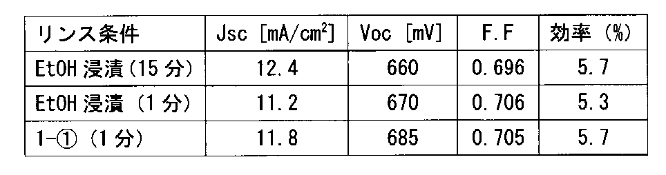
- the substrate was taken out from the adsorption device 100 and rinsed by immersing it in stationary ethanol for 1 minute or 15 minutes.
- the results shown in Table 2 were obtained. The efficiencies were 5.3% and 5.7%, respectively.
- characteristics of a cell prepared by rinsing for 1 minute with the interval C1 being 1 mm and the rinsing liquid flow rate being 27000 mm 3 / s As a result, the results shown in Table 2 were obtained, and the conversion efficiency was 5.7%. That is, when the photosensitizing dye-soluble adsorption device 100a shown in FIG.
- the rinse liquid is circulated for 1 minute in the same manner as the photosensitizing dye adsorption.
- the same characteristics as those obtained by rinsing by immersing in stationary ethanol for 15 minutes can be obtained, and higher characteristics can be obtained than when rinsing by immersing in stationary ethanol for 1 minute. Therefore, the photosensitizing dye could be rinsed efficiently in a short time.
- the production process of the dye-sensitized solar cell is speeded up and the cost is reduced, and the photoelectric conversion of the dye-sensitized solar cell manufactured in the system including the dye adsorption process is performed. It is possible to provide a manufacturing apparatus and a manufacturing method of a dye-sensitized solar cell capable of improving efficiency.
- this invention is not limited to said embodiment and Example, Of course, various deformation
- the dye-sensitized solar cell manufacturing apparatus and the dye-sensitized solar cell manufacturing method of the present invention can be used in the field of manufacturing dye-sensitized solar cells. Therefore, it has industrial applicability.
Landscapes
- Engineering & Computer Science (AREA)
- Power Engineering (AREA)
- Chemical & Material Sciences (AREA)
- Chemical Kinetics & Catalysis (AREA)
- Electrochemistry (AREA)
- Microelectronics & Electronic Packaging (AREA)
- Hybrid Cells (AREA)
- Photovoltaic Devices (AREA)
Abstract
Description
次に、実施例について説明する。60mm×70mm×3mmの酸化スズにフッ素をドーピングしたFTOの薄膜つきガラス基板(日本板硝子、9~10Ω/□)を使用した。次に、FTO膜付き基板のFTO膜の上に、酸化チタン多孔質薄膜を形成した。酸化チタンは、市販の酸化チタンペーストTi-NanoxideD/SP(SOLARONIX)を使用した。これを、FTO膜付き基板のFTO膜上に、スクリーン印刷法を用いて50mm×50mmの範囲(後述する色素吸着量の評価時)若しくは、5mm×5mmの範囲(後述する特性評価時)に塗布して500度の電気炉で焼成後、8μm±0.5μmの厚さになるようにした。

Claims (19)
- 色素増感太陽電池の作用極として機能する電極材料層に、光増感色素溶液を接触させ光増感色素を吸着させる色素増感太陽電池の製造装置であって、
前記電極材料層が表面に形成された基板を収容する密閉容器状の基板収容部と、
前記基板収容部に収容された前記基板の表面を通過するように前記光増感色素溶液を循環させる循環機構と、
を具備し、
前記基板収容部における前記基板と対向する部分の前記光増感色素溶液の流路の断面積が、他の部分の前記光増感色素溶液の流路の断面積よりも小さく構成されている
ことを特徴とする色素増感太陽電池の製造装置。 - 請求項1記載の色素増感太陽電池の製造装置であって、
前記基板収容部の前記基板と対向する部位に、前記光増感色素溶液の流路内に突出する着脱自在の突出部が設けられ、当該突出部を変更することによって、前記基板収容部における前記基板と対向する部分の前記光増感色素溶液の流路の断面積を変更可能とされていることを特徴とする色素増感太陽電池の製造装置。 - 請求項1又は2記載の色素増感太陽電池の製造装置であって、
前記基板収容部には複数の前記基板が配置されることを特徴とする色素増感太陽電池の製造装置。 - 請求項1~3いずれか1項記載の色素増感太陽電池の製造装置であって、
前記光増感色素溶液の流れを反転させる反転機構を具備したことを特徴とする色素増感太陽電池の製造装置。 - 請求項1~4いずれか1項記載の色素増感太陽電池の製造装置であって、
前記光増感色素溶液の温度を制御する温度制御機構を具備したことを特徴とする色素増感太陽電池の製造装置。 - 請求項1~5いずれか1項記載の色素増感太陽電池の製造装置であって、
前記光増感色素溶液の流量を制御する流量制御機構を具備したことを特徴とする色素増感太陽電池の製造装置。 - 請求項1~6いずれか1項記載の色素増感太陽電池の製造装置であって、
前記光増感色素溶液の濃度を検出する濃度測定器を具備したことを特徴とする色素増感太陽電池の製造装置。 - 請求項1~7いずれか1項記載の色素増感太陽電池の製造装置であって、
前記光増感色素をリンスするためのリンス液を貯留するリンス液タンクを具備し、前記光増感色素溶液と切り替えて前記基板収容部に前記リンス液を循環可能に構成されていることを特徴とする色素増感太陽電池の製造装置。 - 請求項8記載の色素増感太陽電池の製造装置であって、
前記リンス液の温度を制御する温度制御機構を具備したことを特徴とする色素増感太陽電池の製造装置。 - 請求項8又は9記載の色素増感太陽電池の製造装置であって、
前記リンス液の流量を制御する流量制御機構を具備したことを特徴とする色素増感太陽電池の製造装置。 - 色素増感太陽電池の作用極として機能する電極材料層に、光増感色素溶液を接触させ光増感色素を吸着させる色素増感太陽電池の製造方法であって、
前記電極材料層が表面に形成された基板を、密閉容器状の基板収容部内に収容するとともに、
前記基板収容部に収容された前記基板の表面と、当該表面と対向する前記基板収容部の対向面との間に形成した隘路を通過させて前記光増感色素溶液を循環させる
ことを特徴とする色素増感太陽電池の製造方法。 - 請求項11記載の色素増感太陽電池の製造方法であって、
前記基板の表面と、前記基板収容部の対向面との間の間隔が5mm以下となるように前記隘路が形成されていることを特徴とする色素増感太陽電池の製造方法。 - 請求項11記載の色素増感太陽電池の製造方法であって、
前記基板の表面と、前記基板収容部の対向面との間の間隔が1mm以下となるように前記隘路が形成されていることを特徴とする色素増感太陽電池の製造方法。 - 請求項11~13いずれか1項記載の色素増感太陽電池の製造方法であって、
前記電極材料層が、金属酸化物半導体多孔質層であることを特徴とする色素増感太陽電池の製造方法。 - 請求項11~14いずれか1項記載の色素増感太陽電池の製造方法であって、
前記光増感色素は、Ru金属錯体系増感色素又は有機色素系増感色素であることを特徴とする色素増感太陽電池の製造方法。 - 請求項11~15いずれか1項記載の色素増感太陽電池の製造方法であって、
前記光増感色素溶液中の前記光増感色素の濃度は0.1mM~1mMの範囲にあることを特徴とする色素増感太陽電池の製造方法。 - 請求項11~16いずれか1項記載の色素増感太陽電池の製造方法であって、
前記基板収容部に複数の前記基板を配置することを特徴とする色素増感太陽電池の製造方法。 - 請求項11~17いずれか1項記載の色素増感太陽電池の製造方法であって、
前記光増感色素溶液の流れを反転させることを特徴とする色素増感太陽電池の製造方法。 - 請求項11~18いずれか1項記載の色素増感太陽電池の製造方法であって、
前記光増感色素を吸着させた後に、前記基板収容部から前記基板を取り出さずに、引き続きリンス処理を行うことを特徴とする色素増感太陽電池の製造方法。
Priority Applications (5)
| Application Number | Priority Date | Filing Date | Title |
|---|---|---|---|
| KR1020127024513A KR101335190B1 (ko) | 2010-02-25 | 2011-02-24 | 색소 증감 태양 전지의 제조 장치 및 색소 증감 태양 전지의 제조 방법 |
| EP11747056A EP2541673A1 (en) | 2010-02-25 | 2011-02-24 | Apparatus for manufacturing dye-sensitized solar cell, and method of manufacturing dye-sensitized solar cell |
| US13/580,782 US8969123B2 (en) | 2010-02-25 | 2011-02-24 | Apparatus for manufacturing dye-sensitized solar cell, and method of manufacturing dye-sensitized solar cell |
| JP2012501683A JP5469741B2 (ja) | 2010-02-25 | 2011-02-24 | 色素増感太陽電池の製造装置及び色素増感太陽電池の製造方法 |
| CN2011800111085A CN102771006A (zh) | 2010-02-25 | 2011-02-24 | 色素增感型太阳电池的制造装置和色素增感型太阳电池的制造方法 |
Applications Claiming Priority (2)
| Application Number | Priority Date | Filing Date | Title |
|---|---|---|---|
| JP2010039846 | 2010-02-25 | ||
| JP2010-039846 | 2010-02-25 |
Publications (1)
| Publication Number | Publication Date |
|---|---|
| WO2011105089A1 true WO2011105089A1 (ja) | 2011-09-01 |
Family
ID=44506516
Family Applications (1)
| Application Number | Title | Priority Date | Filing Date |
|---|---|---|---|
| PCT/JP2011/001069 Ceased WO2011105089A1 (ja) | 2010-02-25 | 2011-02-24 | 色素増感太陽電池の製造装置及び色素増感太陽電池の製造方法 |
Country Status (7)
| Country | Link |
|---|---|
| US (1) | US8969123B2 (ja) |
| EP (1) | EP2541673A1 (ja) |
| JP (1) | JP5469741B2 (ja) |
| KR (1) | KR101335190B1 (ja) |
| CN (1) | CN102771006A (ja) |
| TW (1) | TWI446567B (ja) |
| WO (1) | WO2011105089A1 (ja) |
Cited By (1)
| Publication number | Priority date | Publication date | Assignee | Title |
|---|---|---|---|---|
| WO2012070176A1 (ja) * | 2010-11-25 | 2012-05-31 | 東京エレクトロン株式会社 | 色素吸着装置及び色素吸着方法 |
Families Citing this family (3)
| Publication number | Priority date | Publication date | Assignee | Title |
|---|---|---|---|---|
| JP5520258B2 (ja) * | 2011-06-29 | 2014-06-11 | 東京エレクトロン株式会社 | 色素吸着装置及び色素吸着方法 |
| TWI604622B (zh) * | 2016-07-14 | 2017-11-01 | 財團法人工業技術研究院 | 電極吸附染料的方法及其裝置 |
| CN106449119B (zh) * | 2016-09-14 | 2018-10-16 | 中国石油天然气股份有限公司 | 一种太阳电池阳极染料浸泡装置及染料浸泡方法 |
Citations (6)
| Publication number | Priority date | Publication date | Assignee | Title |
|---|---|---|---|---|
| JP2001185244A (ja) * | 1999-12-27 | 2001-07-06 | Sharp Corp | 色素増感型太陽電池及び色素増感型太陽電池の作製方法並びに太陽電池モジュール |
| JP2002075472A (ja) * | 2000-08-25 | 2002-03-15 | Sharp Corp | カラー太陽電池およびその作製方法 |
| JP2004014370A (ja) * | 2002-06-07 | 2004-01-15 | Mitsubishi Chemicals Corp | 酸化物半導体電極及び光電変換素子 |
| JP2008071535A (ja) | 2006-09-12 | 2008-03-27 | Kyushu Institute Of Technology | 光電変換素子及びその製造方法 |
| JP2008243752A (ja) * | 2007-03-29 | 2008-10-09 | Tdk Corp | 電極及びその製造方法、並びに色素増感型太陽電池 |
| JP2010009830A (ja) * | 2008-06-25 | 2010-01-14 | Konica Minolta Business Technologies Inc | 光電変換素子及びその製造方法、太陽電池 |
Family Cites Families (10)
| Publication number | Priority date | Publication date | Assignee | Title |
|---|---|---|---|---|
| JPS5864368A (ja) * | 1981-10-12 | 1983-04-16 | Inoue Japax Res Inc | 化学メツキ方法 |
| US4911761A (en) * | 1984-05-21 | 1990-03-27 | Cfm Technologies Research Associates | Process and apparatus for drying surfaces |
| DE19513888A1 (de) * | 1995-04-19 | 1996-10-24 | Focke & Co | Verfahren und Vorrichtung zum Auftragen von Markierungen, insbesondere Farbmarkierungen, auf Folienbahnen |
| JP3704054B2 (ja) * | 2001-05-01 | 2005-10-05 | 東京エレクトロン株式会社 | 処理液の濃度を変更する方法及び処理液供給装置 |
| JP4254278B2 (ja) * | 2003-03-04 | 2009-04-15 | パナソニック電工株式会社 | 太陽電池作製キットおよびそれを用いた太陽電池の作製方法 |
| KR100589322B1 (ko) * | 2004-02-03 | 2006-06-14 | 삼성에스디아이 주식회사 | 고효율 염료감응 태양전지 및 그 제조 방법 |
| EP2036955B1 (en) | 2007-09-17 | 2012-05-16 | JSR Corporation | Dyestuff, dye-sensitized solar cell, and method for manufacturing same |
| KR20090049703A (ko) | 2007-11-14 | 2009-05-19 | 주식회사 동진쎄미켐 | 염료감응 태양전지 수명연장 방법 및 수명연장 장치 |
| CN101509306B (zh) * | 2009-03-20 | 2011-02-02 | 大连理工大学 | 基于染料敏化太阳能电池的光电一体化建筑材料 |
| KR20110012550A (ko) * | 2009-07-30 | 2011-02-09 | 삼성전자주식회사 | 박막 태양 전지의 제조방법 및 제조장치 |
-
2011
- 2011-02-24 JP JP2012501683A patent/JP5469741B2/ja not_active Expired - Fee Related
- 2011-02-24 US US13/580,782 patent/US8969123B2/en not_active Expired - Fee Related
- 2011-02-24 TW TW100106279A patent/TWI446567B/zh not_active IP Right Cessation
- 2011-02-24 WO PCT/JP2011/001069 patent/WO2011105089A1/ja not_active Ceased
- 2011-02-24 EP EP11747056A patent/EP2541673A1/en not_active Withdrawn
- 2011-02-24 KR KR1020127024513A patent/KR101335190B1/ko not_active Expired - Fee Related
- 2011-02-24 CN CN2011800111085A patent/CN102771006A/zh active Pending
Patent Citations (6)
| Publication number | Priority date | Publication date | Assignee | Title |
|---|---|---|---|---|
| JP2001185244A (ja) * | 1999-12-27 | 2001-07-06 | Sharp Corp | 色素増感型太陽電池及び色素増感型太陽電池の作製方法並びに太陽電池モジュール |
| JP2002075472A (ja) * | 2000-08-25 | 2002-03-15 | Sharp Corp | カラー太陽電池およびその作製方法 |
| JP2004014370A (ja) * | 2002-06-07 | 2004-01-15 | Mitsubishi Chemicals Corp | 酸化物半導体電極及び光電変換素子 |
| JP2008071535A (ja) | 2006-09-12 | 2008-03-27 | Kyushu Institute Of Technology | 光電変換素子及びその製造方法 |
| JP2008243752A (ja) * | 2007-03-29 | 2008-10-09 | Tdk Corp | 電極及びその製造方法、並びに色素増感型太陽電池 |
| JP2010009830A (ja) * | 2008-06-25 | 2010-01-14 | Konica Minolta Business Technologies Inc | 光電変換素子及びその製造方法、太陽電池 |
Cited By (4)
| Publication number | Priority date | Publication date | Assignee | Title |
|---|---|---|---|---|
| WO2012070176A1 (ja) * | 2010-11-25 | 2012-05-31 | 東京エレクトロン株式会社 | 色素吸着装置及び色素吸着方法 |
| JP2012113981A (ja) * | 2010-11-25 | 2012-06-14 | Tokyo Electron Ltd | 色素吸着装置 |
| CN103222107A (zh) * | 2010-11-25 | 2013-07-24 | 东京毅力科创株式会社 | 色素吸附装置及色素吸附方法 |
| US9093222B2 (en) | 2010-11-25 | 2015-07-28 | Tokyo Electron Limited | Dye adsorption apparatus and dye adsorption method |
Also Published As
| Publication number | Publication date |
|---|---|
| CN102771006A (zh) | 2012-11-07 |
| JP5469741B2 (ja) | 2014-04-16 |
| KR101335190B1 (ko) | 2013-11-29 |
| KR20120127508A (ko) | 2012-11-21 |
| US8969123B2 (en) | 2015-03-03 |
| EP2541673A1 (en) | 2013-01-02 |
| JPWO2011105089A1 (ja) | 2013-06-20 |
| US20130034930A1 (en) | 2013-02-07 |
| TW201205851A (en) | 2012-02-01 |
| TWI446567B (zh) | 2014-07-21 |
Similar Documents
| Publication | Publication Date | Title |
|---|---|---|
| Dong et al. | Insight into perovskite solar cells based on SnO2 compact electron-selective layer | |
| Hashmi et al. | Dye-sensitized solar cells with inkjet-printed dyes | |
| Chen et al. | Ionic liquid-tethered nanoparticle/poly (ionic liquid) electrolytes for quasi-solid-state dye-sensitized solar cells | |
| Lin et al. | Honeycomb-like CoS counter electrodes for transparent dye-sensitized solar cells | |
| Chen et al. | Polyvinyl butyral-based thin film polymeric electrolyte for dye-sensitized solar cell with long-term stability | |
| Lu et al. | The degradation of dye sensitized solar cell in the presence of water isotopes | |
| Ito et al. | Study of Dye‐Sensitized Solar Cells by Scanning Electron Micrograph Observation and Thickness Optimization of Porous TiO2 Electrodes | |
| Najafabadi et al. | The influence of radio-frequency sputtered blocking layer on boosting the performance of BaSnO3-based dye-sensitized solar cell | |
| Giordano et al. | Series-connection designs for dye solar cell modules | |
| Congiu et al. | Single precursor route to efficient cobalt sulphide counter electrodes for dye sensitized solar cells | |
| JP5469741B2 (ja) | 色素増感太陽電池の製造装置及び色素増感太陽電池の製造方法 | |
| WO2009017298A1 (en) | Method of forming porous layer, dye-sensitized solar cell using the same, and method of fabricating the dye-sensitized solar cell | |
| Shi et al. | Silica nanoparticle doped organic ionic plastic crystal electrolytes for highly efficient solid-state dye-sensitized solar cells | |
| Molla et al. | Transparent conductive oxide‐less back contact dye‐sensitized solar cells using cobalt electrolyte | |
| Chiappara et al. | Investigation of recovery mechanisms in dye sensitized solar cells | |
| Di Cheng et al. | Effect of ruthenium (II)-bipyridine complex photosensitizer on the panchromatic light absorption and electron transfer in N719-dye sensitized photoanodes | |
| Li et al. | Efficient organic dye sensitized solar cells based on modified sulfide/polysulfide electrolyte | |
| Molla et al. | Parametric optimization of back-contact TCO-free dye-sensitized solar cells employing indoline and porphyrin sensitizer based on cobalt redox electrolyte | |
| Wang et al. | A light-scattering co-adsorbent for performance improvement of dye-sensitized solar cells | |
| CA2751542A1 (en) | Dye-sensitised solar cells | |
| Congiu et al. | An open-source equipment for thin film fabrication by electrodeposition, dip coating, and SILAR | |
| KR101256473B1 (ko) | 염료감응형 태양전지용 일전극과 이를 구비하는 염료감응형 태양전지 및 그 제조 방법 | |
| Wei et al. | Hydrophobic electrolyte pastes for highly durable dye-sensitized solar cells | |
| JP2005243498A (ja) | 酸化物半導体電極の製造方法および色素増感型太陽電池の製造方法 | |
| JP5131732B2 (ja) | 色素増感太陽電池用の色素吸着半導体電極の製造方法 |
Legal Events
| Date | Code | Title | Description |
|---|---|---|---|
| WWE | Wipo information: entry into national phase |
Ref document number: 201180011108.5 Country of ref document: CN |
|
| 121 | Ep: the epo has been informed by wipo that ep was designated in this application |
Ref document number: 11747056 Country of ref document: EP Kind code of ref document: A1 |
|
| WWE | Wipo information: entry into national phase |
Ref document number: 2012501683 Country of ref document: JP |
|
| NENP | Non-entry into the national phase |
Ref country code: DE |
|
| ENP | Entry into the national phase |
Ref document number: 20127024513 Country of ref document: KR Kind code of ref document: A |
|
| REEP | Request for entry into the european phase |
Ref document number: 2011747056 Country of ref document: EP |
|
| WWE | Wipo information: entry into national phase |
Ref document number: 13580782 Country of ref document: US Ref document number: 2011747056 Country of ref document: EP |