WO2011105276A1 - タンポンの製造方法、及び、タンポンの製造装置 - Google Patents
タンポンの製造方法、及び、タンポンの製造装置 Download PDFInfo
- Publication number
- WO2011105276A1 WO2011105276A1 PCT/JP2011/053355 JP2011053355W WO2011105276A1 WO 2011105276 A1 WO2011105276 A1 WO 2011105276A1 JP 2011053355 W JP2011053355 W JP 2011053355W WO 2011105276 A1 WO2011105276 A1 WO 2011105276A1
- Authority
- WO
- WIPO (PCT)
- Prior art keywords
- string
- tampon
- absorber
- holding
- gripping
- Prior art date
- Legal status (The legal status is an assumption and is not a legal conclusion. Google has not performed a legal analysis and makes no representation as to the accuracy of the status listed.)
- Ceased
Links
Images


Classifications
-
- A—HUMAN NECESSITIES
- A61—MEDICAL OR VETERINARY SCIENCE; HYGIENE
- A61F—FILTERS IMPLANTABLE INTO BLOOD VESSELS; PROSTHESES; DEVICES PROVIDING PATENCY TO, OR PREVENTING COLLAPSING OF, TUBULAR STRUCTURES OF THE BODY, e.g. STENTS; ORTHOPAEDIC, NURSING OR CONTRACEPTIVE DEVICES; FOMENTATION; TREATMENT OR PROTECTION OF EYES OR EARS; BANDAGES, DRESSINGS OR ABSORBENT PADS; FIRST-AID KITS
- A61F13/00—Bandages or dressings; Absorbent pads
- A61F13/15—Absorbent pads, e.g. sanitary towels, swabs or tampons for external or internal application to the body; Supporting or fastening means therefor; Tampon applicators
- A61F13/20—Tampons, e.g. catamenial tampons; Accessories therefor
- A61F13/2082—Apparatus or processes of manufacturing
- A61F13/2085—Catamenial tampons
Definitions
- the present invention relates to a tampon manufacturing method and a tampon manufacturing apparatus.
- Tampons are widely known as sanitary products.
- a string is attached to one end of an absorber that absorbs liquid such as menstrual blood.
- This string is pulled by the user when the absorber inserted in the vaginal cavity is taken out of the vaginal cavity.
- the string supply section when attaching the string to the absorbent body, check whether the string has a defective part such as a knot or pill, and remove the tampon attached with the defective string from the production line Manufacturing methods have been proposed. (For example, refer to Patent Document 1).
- This invention is made
- a main invention for achieving the above object is a method of manufacturing a tampon having an absorber that absorbs liquid and a string attached to the absorber, and attaching the string to the absorber.
- the movement of the absorber is regulated by the regulating part, the string is grasped by the gripping part, and the gap between the regulating part and the gripping part in the longitudinal direction of the absorber is widened to the string.
- a method for producing a tampon comprising: applying tension.
- a tampon manufacturing method and a tampon manufacturing apparatus in which a string is normally attached to an absorbent body are realized.
- FIG. 1A is a cross-sectional view showing components of the tampon
- FIG. 1B is a view showing a state in which a string is attached to an absorbent body serving as a tampon body
- FIG. 1C is an external view of the tampon body.
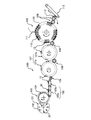
- It is the schematic diagram which looked at the manufacturing apparatus of a tampon from the front.
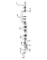
- It is the schematic diagram which looked at the manufacturing apparatus of a tampon from the upper part.
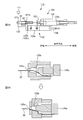
- 5A and 5B are diagrams for explaining the string pulling unit.
- FIG. 6A to FIG. 6C are diagrams for explaining the inspection results when the string is normally attached to the absorber.
- FIG. 7C are diagrams for explaining the inspection results when the string is normally attached to the absorber.
- FIG. 8A to FIG. 8C are diagrams for explaining the inspection results when the string is not normally attached to the absorber.
- FIG. 9A to FIG. 9C are diagrams for explaining the inspection results when the string is not attached to the absorber.
- 10A and 10B are diagrams for explaining other string tension inspections.
- FIG. 11A and FIG. 11B are diagrams for explaining string tension inspection of a tampon without an applicator.
- a manufacturing method of a tampon having an absorber that absorbs liquid and a string attached to the absorber, the attachment of the string to the absorber, and the movement of the absorber by a restriction unit Regulating, gripping the string with a gripping part, and widening the distance between the regulation part and the gripping part in the longitudinal direction of the absorbent body to apply tension to the string.
- the tampon comprises an applicator comprising: an outer cylinder that houses the absorber; and an inner cylinder that moves through the outer cylinder and pushes the absorber from the tip of the outer cylinder. And the string is exposed from a rear end of the inner cylinder, and the restricting portion restricts movement of the applicator and restricts movement of the absorber through an end surface of the inner cylinder. . According to such a tampon manufacturing method, it is possible to inspect whether or not the string is normally attached to the absorber.
- the tampon has a defective product discharge section that discharges the tampon, which is poorly attached to the absorbent body, out of the manufacturing process.
- the defective product discharge portion takes the tampon out of the manufacturing process at the calculated timing.
- a product in which the attachment of the string to the absorbent body is defective can be discharged out of the manufacturing process, and a product in which the string is normally attached to the absorbent body can be provided. .
- one of the restricting portion and the gripping portion is a fixed portion whose position is fixed, and the other of the restricting portion and the gripping portion is movable in the longitudinal direction.
- a sensor is located at a predetermined distance from the fixed part to the moving part side, and based on the detection result of the sensor after the interval is widened, the string on the absorber Check for mounting defects. According to such a tampon manufacturing method, it can be determined whether or not the string is normally attached to the absorbent body.
- the moving unit is located at a point detected by the sensor before widening the interval, and when the string attachment is poor, The moving unit is located at a point not detected by the sensor. According to such a tampon manufacturing method, it is possible to detect a product in which the string is not properly attached to the absorber.
- the moving part is positioned at a point detected by the sensor before the interval is widened, the string is normally attached, and the string is loosened and gripped by the gripping part. If it is, the moving unit is positioned at a point detected by the sensor after widening the interval. According to such a tampon manufacturing method, even if the string is loosened and gripped, if the string attachment is normal, it is determined that the string attachment is a normal product.
- the gripping part grips the string while sucking in the suction part from the side where the string extends from the absorber.
- the gripping portion can grip the string while suppressing the slack of the string.
- a tampon manufacturing device having an absorber that absorbs liquid and a string attached to the absorber, and an attachment device that attaches the string to the absorber, and restricts the movement of the absorber.
- FIG. 1A is a cross-sectional view showing components of the tampon 10
- FIG. 1B is a view showing a state in which a string 22 is attached to an absorbent body 21 that becomes the tampon main body 20
- FIG. 1C is an external view of the tampon main body 20.
- the tampon 10 of the present embodiment has a tampon body 20 and an applicator 30 as shown in FIG.
- the applicator 30 includes an outer cylinder member 40 (corresponding to an outer cylinder) that accommodates the tampon main body 20, and a moving member 50 (corresponding to an inner cylinder) for moving the tampon main body 20 relative to the outer cylinder member 40.
- This is an auxiliary tool for facilitating the introduction of the tampon body 20 into the vaginal cavity.
- the tampon main body 20 closes the vaginal cavity and absorbs liquid such as menstrual blood, and has an absorber 21 and a string 22.
- the absorbent body 21 is formed by, for example, covering an absorbent body material 211 (cotton body) in which absorbent fibers mainly composed of rayon are laminated with a cover body 212 made of a polyester spunbonded nonwoven fabric, and is molded into a bullet shape.
- a string 22 is sewn to the absorber 21.
- the string 22 is, for example, a cotton twisted yarn.
- the string 22 extends from the rear end side of the absorbent body 21, and is pulled by the user of the tampon 10 or the like when the absorbent body 21 in the vaginal cavity is pulled out of the vaginal cavity.
- the string 22 passes through the applicator 30, that is, the inside of the cylindrical outer cylinder member 40 and the moving member 50, and is exposed from the rear end of the applicator 30.
- the outer cylinder member 40 is for accommodating the tampon main body 20 so as to be relatively movable.
- the outer cylinder member 40 is a cylindrical body that is injection-molded using a thermoplastic resin (for example, polyethylene resin), and has appropriate flexibility.
- the outer cylinder member 40 includes a large-diameter portion 41 on the front end side and a small-diameter portion 42 on the rear end side.
- the inner diameter (and outer diameter) of the large diameter portion 41 is larger than the inner diameter (and outer diameter) of the small diameter portion 42. Therefore, an annular step 45 is formed between the large diameter portion 41 and the small diameter portion 42.
- the large diameter portion 41 plays a role of housing the tampon main body 20 and is a portion that is inserted into the vaginal cavity in a state in which the tampon main body 20 is stored when the tampon 10 is used.
- a plurality of cuts 44 are formed at the distal end portion of the large-diameter portion 41 and can be opened (hereinafter referred to as the distal end opening 43). Therefore, after the outer cylinder member 40 is inserted into the vaginal cavity, when the tampon body 20 is pushed by the moving member 50 (described later), the distal end opening 43 is pushed and expanded by the tampon body 20, and the tampon body 20 is moved to the outer cylinder member. 40 is exposed. In addition, after the tampon main body 20 is pushed out from the outer cylinder member 40, the user of the tampon 10 takes out the applicator 30 from the vaginal cavity, whereby the mounting of the tampon main body 20 is completed.
- the small diameter portion 42 functions as a guide for guiding the moving member 50 when the moving member 50 moves inside thereof.
- the small diameter portion 42 is also a portion that is gripped by the user when the tampon 10 is mounted.
- the moving member 50 is configured to be movable in the longitudinal direction in the outer cylinder member 40 and to push the tampon main body 20 out of the outer cylinder member 40 from the tip opening 43.
- the distal end of the moving member 50 is a locking portion 51 whose outer diameter is larger than the inner diameter of the small diameter portion 42. Therefore, when the moving member 50 is pulled to the rear end side, the step portion 45 and the locking portion 51 of the outer cylinder member 40 come into contact with each other, and the moving member 50 is configured not to come out of the outer cylinder member 40. Yes.
- an annular protrusion 52 is provided at the rear end of the moving member 50.
- the annular protrusion 52 is configured to abut against the rear end portion of the small diameter portion 42 of the outer cylinder member 40 when the moving member 50 is pushed to the front end side, so that the moving member 50 does not come out of the outer cylinder member 40. ing.
- FIG. 2 is a schematic view of the tampon manufacturing apparatus 100 as viewed from the front.
- FIG. 3 is a schematic view of the tampon manufacturing apparatus 100 as viewed from above.
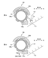
- FIG. 4 is a schematic diagram of the defective product discharge unit 112. The tampon 10 is assembled after the tampon body 20 and the applicator 30 are manufactured in separate steps.
- the tampon manufacturing apparatus 100 includes a compression molding drum 101 that forms the absorbent body 21 of the tampon body 20, a heating drum 103 that heats the absorbent body 21, and an assembly that assembles the tampon body 20 and the applicator 30.
- a heating drum 107a that heats the unit 105 and the distal end opening 43 of the outer cylinder member 40 in which the tampon main body 20 is accommodated in a closing direction, and a cooling drum 107b that maintains and cools the curved distal end opening 43
- a “string inspection unit 109” for inspecting whether or not the string 22 is normally attached to the absorber 21 while the tampon 10 is conveyed by the rotating drum 108, and a defective product discharge unit 112.
- molding apparatus etc. of the applicator 30 are abbreviate
- a material in which an absorbent material 211 that is a base material of the absorbent body 21 is covered with a cover body 212 is cut into a predetermined shape and size.
- the string 22 is attached (sewn) to the cut cover body 212 and the absorbent body material 211 (absorber body 21) by an attachment device (not shown).
- the string 22 is sewn from the front end in the longitudinal direction of the absorber 21 to the rear end.
- the tampon main body 20 is inserted into the holding mechanisms 102 arranged radially by the compression molding drum 101.
- the absorber 21 is compressed in the diametrical direction during the rotational movement of the compression molding drum 101 and is formed into a substantially cylindrical shape.
- the absorber 21 formed in a columnar shape is heated by the heating drum 103.
- the temperature of the heating drum 103 is not less than 100 degrees and not more than 180 degrees, preferably 110 degrees.
- the holding mechanism 104 of the heating drum 103 into which the tampon main body 20 is inserted is a through hole having substantially the same shape as the cross section of the absorber 21, so that the heat of the heating drum 103 is effectively transmitted to the absorber 21. .
- the absorber 21 is molded into a bullet shape in which the tip of the absorber 21 forms a curved surface.
- the assembly unit 105 includes a first conveyor 105a and a second conveyor 105b.
- the tampon main body 20 pushed out from the holding mechanism 104 of the heating drum 103 is conveyed on the first conveyor 105a while maintaining the orientation at that time.
- the applicator 30 manufactured in a separate line is supplied to the second conveyor 105b.
- the moving member 50 is inserted into the outer cylinder member 40. As shown in FIG. 1A, the moving member 50 is located on the rear end side in the longitudinal direction with respect to the outer cylinder member 40.
- the step portion 45 and the locking portion 51 of the moving member 50 are in contact with each other.
- tip opening 43 of the outer cylinder member 40 is pushed and expanded on the outer peripheral side.
- the tampon main body 20 on the first conveyor 105a is inserted into the applicator 30 on the second conveyor 105b (inside the outer cylinder member 40) from the rear end side.
- air is sucked from the rear end side of the moving member 50 so that the string 22 of the tampon main body 20 precedes.
- the string 22 is pulled out from the opening at the rear end of the moving member 50 (that is, the rear end of the applicator 30) and is exposed.
- the tip molding unit 107 has a heating drum 107a, a cooling drum 107b, and a tip mold portion (not shown) having a hemispherical recess.
- the heated tip mold portion (not shown) is pressed toward the tip opening 43 side of the outer cylinder member 40, so that the petal-like portion is curved inward (in the closing direction) to form a dome shape. It is formed.
- the tip mold portion (not shown) is pressed against the petal-like portion of the outer cylindrical member 40 that has been heated and softened, and is cooled and cured. As a result, when the tampon main body 20 is accommodated in the outer cylinder member 40, the tip opening 43 is substantially closed as shown in FIG. 1A.
- the string inspection unit 109 (corresponding to an inspection apparatus) includes a string pulling unit 110, a sensor 111, a rotating drum 108, and a control unit (not shown).
- a plurality of string pulling units 110 are arranged along the circumferential direction of the rotary drum 108.
- the string pulling unit 110 holds the tampon 10 supplied from the relay roller 106.
- the longitudinal direction of the tampon 10 and the direction along the rotation axis of the drum coincide.
- the sensor 111 is located on the top of the rotating drum 108 (direction at 12 o'clock).
- the string inspection unit 109 performs an inspection (string tension inspection) as to whether or not the string 22 is normally attached to the absorber 21.
- a product in which the string 22 is not normally attached to the absorbent body 21 is, for example, a product in which the string 22 is not originally sewn to the absorbent body 21 due to a sewing needle being removed or a string 22 having a defective portion is sewn.
- Products that are attached or that the string 22 is brazed in a later process the string 22 is cut and the string 22 does not satisfy the specified length, or the string 22 is likely to be broken, or absorption Examples are products in which the string 22 is not easily sewn to the body 21 and the string 22 is likely to come off from the absorbent body 21.
- the string gripping part 125 grips the string 22 of the absorbent body 21 exposed from the rear end of the moving member 50, and the tampon holding parts 121a and 121b are connected to the absorbent body 21 via the applicator 30.
- the distance between the string gripping portion 125 and the tampon holding portions 121a and 121b is increased in the longitudinal direction.
- tensile_strength is given to the string 22 and it is test
- the relay roller 106 includes a rotating body 106a, and a first outer wall 106b and a second outer wall 106c that cover the outer periphery of the rotating body 106a.
- the rotating body 106a is provided with a plurality of grooves for accommodating the tampon 10 in the circumferential direction.
- the tampon 10 housed in the groove of the rotating body 106a is not held by a clamp or the like, and the tampon 10 is surrounded by the groove of the rotating body 106a and the first outer wall 106b up to the defective product discharge unit 112. Be transported.
- the defective product discharger 112 can cover a part of the outer peripheral surface of the rotating body 106a between the first outer wall 106b and the second outer wall 106c. Therefore, the side surface of the defective product discharger 112 on the relay roller 106 side is a surface along the outer periphery of the rotating body 106a. Furthermore, the defective product discharger 112 is movable in the lateral direction, which is a direction intersecting the rotation axis of the rotating body 106a. Therefore, as shown in FIG.
- the defective product discharger 112 can be positioned apart from the first outer wall 106b and the second outer wall 106c with a space between the rotating body 106a and the defective product discharger 112, and 4B, the first outer wall 106b and the second outer wall 106c may be positioned.
- the control unit of the string inspection unit 109 controls the position of the defective product discharge unit 112 in the horizontal direction.
- the control unit of the string inspection unit 109 indicates that the string 22 is normally attached to the absorber 21 in the tampon 10. Assume that you have determined.
- the control unit separates the defective product discharge unit 112 from the first outer wall 106b and the second outer wall 106c as shown in FIG. A space is provided between the defective product discharge unit 112.
- the tampon 10 on the conveyor belt 113 is conveyed to a subsequent process (for example, a packaging process).
- the control unit of the string inspection unit 109 shows that the string 22 is normally attached to the absorber 21 in the tampon 10.
- the control unit positions the defective product discharge unit 112 between the first outer wall 106b and the second outer wall 106c as shown in FIG. 4B.
- the tampon 10 is separated from the first outer wall 106 b, the tampon 10 is surrounded by the groove of the rotating body 106 a and the defective product discharge unit 112, and thus reaches the second outer wall 106 c without falling on the conveyor belt 113. To do. There is no object covering the outer surface of the rotating body 106a on the downstream side of the second outer wall 106c, and the tampon 10 is separated from the rotating body 106a and discharged outside the manufacturing process.
- the control unit of the string inspection unit 109 determines the position of the defective product discharge unit 112 in the lateral direction at the timing when the tampon 10 reaches the defective product discharge unit 112 based on the result of the string tension inspection of a certain tampon 10. Control. Then, the control unit supplies the product (non-defective product) that has passed the string tension inspection to the conveyor belt 113 that follows the subsequent process, and the product (defective product) that has failed the string tension inspection is out of the manufacturing process. Discharge. As a result, the tampon 10 in which the string 22 is normally attached to the absorber 21 can be manufactured and provided.
- the control unit of the string inspection unit 109 calculates the timing at which a certain tampon that has performed the string tension inspection reaches the defective product discharge unit 112. Therefore, for example, the control unit calculates a time from when a tampon 10 is inspected to pull a certain tampon 10 until the tampon 10 reaches the defective product discharging unit 112. The conveyance distance from the point where the sensor 111 of the string inspection unit 109 shown in FIG. 2 and the tampon 10 face each other until the tampon 10 reaches the defective product discharge unit 112, the conveyance speed of the tampon 10 in the tampon manufacturing apparatus 100, Based on this, the time can be calculated.
- the tampon 10 which does not pass the string tension inspection is discharged out of the manufacturing process by controlling the position in the lateral direction of the defective product discharge unit 112 here
- the present invention is not limited to this.
- the rejected product may be discharged out of the manufacturing process at the timing of releasing the clamp that extends from one end of the groove of the relay roller 106 to the other end.
- the tampon 10 supplied to the relay roller 106 is held by a clamp, and the tampon 10 to which the string 22 is normally attached releases the clamp at the timing when it reaches the conveyor belt 113.
- the clamp is not released at the timing when it reaches the conveyor belt 113 but is released at the timing when it is discharged out of the manufacturing process.
- the tampon 10 to which the string 22 is normally attached and the tampon 10 to which the string 22 is not normally attached can be sorted.
- the string pulling unit 110 includes a holding stand 120, tampon holding parts 121a and 121b (corresponding to a restricting part) that restrict the movement of the absorber 21 via the applicator 30, a moving air cylinder 122, a string gripping mechanism 123, Have The tampon 10 is provided on the holding table 120, and the tampon holding parts 121 a and 121 b are provided on the upper surface of the holding table 120.
- the holding table 120 is provided at the tip of the piston rod 122b of the moving air cylinder 122. Therefore, the holding stand 120 is movable in the longitudinal direction together with the tampon 10 (applicator 30) held by the tampon holding portions 121a and 121b.
- the moving air cylinder 122 has a main body portion 122a provided with a cylinder tube, and a piston unit 122c in which a piston movable in the cylinder tube and a piston rod 122b are integrally formed.
- the holding stand 120 and the piston are connected.
- the main body 122a is fixed to the rotating drum 108 (see FIG. 2) and rotates together with the rotating drum 108.
- a string gripping mechanism 123 is also attached to the main body 122a.
- the string gripping mechanism 123 includes a string gripping air cylinder 124, a string gripping part 125 (corresponding to a gripping part), and a suction part 126.
- the string gripping air cylinder 124 has a rod portion 124a, and the rod portion 124a is movable in the longitudinal direction.
- gripping part 125 is provided in the front-end
- FIG. 5B is an enlarged view of the string gripping portion 125.
- the string gripping portion 125 is provided with an opening 125a.
- the opening 125a has a tapered portion 125b that widens from the outside to the inside.
- the rod portion 124a of the string gripping air cylinder 124 is urged to the distal end side in the longitudinal direction by a coil spring, and the distal end of the rod portion 124a presses the tapered portion 125b, thereby opening the opening 125a. Blocked.
- the string gripping mechanism 123 is provided on the rear end side of the tampon 10 supported by the holding base 120, and is arranged so that the center of the tampon main body 20 and the opening 125a are located on a substantially straight line.
- the tampon 10 is delivered to the holding table 120 of the string pulling unit 110 via the relay roller 106 after the tip molding unit 107. At this time, no air is supplied to the moving air cylinder 122. Therefore, the piston rod 122b does not extend, and as shown in FIG. 5A, the holding table 120 and the main body 122a are located relatively close to each other.
- the clamp of the tampon holding portion 121b on the rear end side is closed and the tampon 10 is held.
- the tampon main body 20 is accommodated in the outer cylinder member 40, and the moving member 50 projects toward the rear end side with respect to the outer cylinder member 40 as shown in FIG. 1A. Therefore, the rear end of the moving member 50 is located relatively close to the opening 125 a of the string gripping portion 125.
- the suction of air from the suction portion 126 is stopped, the rod portion 124a is urged toward the distal end side in the longitudinal direction by the coil spring, and the distal end of the rod portion 124a presses the tapered portion 125b (lower view in FIG. 5B).
- the string 22 is sandwiched between the rod part 124a and the tapered part 125b, and the string gripping part 125 grips the string 22.
- the string gripping part 125 grips the string 22 while the suction part 126 sucks in from the rear end side of the absorber 21, so that the string gripping part 125 can grip the string 22 while suppressing slack of the string. I can do it. Further, the string 22 that is not exposed from the moving member 50 can be exposed from the moving member 50 by the suction of the suction part 126, and the string gripping part 125 can grip the string 22.
- the rotary drum 108 of the string inspection unit 109 continues to rotate. Then, before the tampon 10 held by the holding table 120 is opposed to the sensor 111, air is supplied to the moving air cylinder 122, and a force for extending the piston rod 122b to the front end in the longitudinal direction acts on the piston rod 122b. . As a result, a force is also exerted on the holding stand 120 and the tampon 10 (outer cylinder member 40) held on the holding stand 120 so as to move them to the front end side in the longitudinal direction.
- the tampon holding portions 121a and 121b (moving portions) that are movable in the longitudinal direction are moved toward the distal end side in the longitudinal direction with respect to the string gripping portion 125 (corresponding to the fixing portion) whose position in the longitudinal direction is fixed.
- maintenance part 121a, 121b is expanded.
- the tampon holding portions 121a and 121b shown in FIG. 5A are composed of a pair of protrusions, and the tampon 10 is disposed between the protrusions to restrict the movement of the tampon 10.
- the large-diameter portion 41 of the outer cylindrical member 40 is positioned between the pair of protruding portions, and in the rear-end tampon holding portion 121b, the outer cylindrical member 40 is positioned between the pair of protruding portions.
- the small diameter portion 42 is located.
- the tampon holding portion 121b on the rear end side is provided with a releasable clamp that spans between the protrusions.
- the movement of the outer cylinder member 40 is restricted on the holding table 120 by the tampon holding portions 121a and 121b.
- the distal end of the moving member 50 is a locking portion 51 whose outer diameter is larger than the inner diameter of the small diameter portion 42 of the outer cylinder member 40. Therefore, the moving member 50 is configured not to come off from the rear end side in the longitudinal direction of the outer cylinder member 40. Therefore, the movement of the inner cylinder member 50 toward the rear end side in the longitudinal direction is also restricted by the tampon holding portions 121a and 121b.
- the absorber 21 is in contact with the end surface on the distal end side of the moving member 50.
- the absorbent body 21 is moved by the tampon holding portions 121a and 121b.
- the movement toward the rear end side in the longitudinal direction is regulated through the front end surface of the.
- the outer diameter of the absorber 21 is larger than the inner diameter of the small diameter portion 42 of the outer cylinder member 40 as shown in FIG. 1A. Also from this, even if tension acts on the string 22 and a force to move the absorber 21 to the rear end side in the longitudinal direction works, the absorber 21 moves to the rear end side in the longitudinal direction within the outer cylinder member 40. I understand that I can't.
- the interval between the protrusions forming the pair of the tampon holding portions 121b on the rear end side is larger than the outer diameter of the small diameter portion 42 of the outer cylinder member 40 and smaller than the outer diameter of the large diameter portion 41. Therefore, even if a tension acts on the string 22 attached to the absorber 21 and a force to move the outer cylinder member 40 toward the rear end in the longitudinal direction acts, the rear of the large-diameter portion 41 of the outer cylinder member 40 The end portion comes into contact with the tampon holding portion 121b on the rear end side, and the movement of the outer cylinder member 40 toward the rear end side in the longitudinal direction can be reliably restricted.
- the movement of the outer cylinder member 40 can be regulated without sliding the tampon holding portions 121a and 121b, and the string 22 Can be given a predetermined tension.
- the string 22 is normally attached to the absorber 21. It can be judged that it was not. Otherwise, it can be determined that the string 22 is normally attached to the absorber 21 (details will be described later).
- the force applied to the piston rod 122b of the moving air cylinder 122 may be adjusted so that the tension applied to the string 22 is larger than 20N and smaller than 100N, preferably 60N. If the force applied to the string 22 is 20 N or less, the force applied to the string 22 when the tampon body 20 is taken out of the vaginal cavity (resistance force) is smaller, and if the force applied to the string 22 is 100 N or more, the absorbent body 21 This is because there is a risk of breaking.
- the tampon holding portions 121a and 121b regulate the movement of the absorber 21 by regulating the movement of the outer cylinder member 40, but the present invention is not limited to this.
- the tampon holding part may regulate the movement of the moving member 50 (inner cylinder) in the longitudinal direction.
- the movement of the absorber 21 toward the rear end side in the longitudinal direction when tension is applied to the string 22 is regulated by bringing the rear end portion of the absorber 21 into contact with the front end surface of the moving member 50. be able to. As a result, a predetermined tension can be applied to the string 22 of the absorber 21.
- the tampon holding portions 121 a and 121 b are absorbed by restricting the movement of the moving member 50 (inner cylinder) in the longitudinal direction.
- the movement of the body 21 toward the rear end side in the longitudinal direction can be restricted.
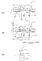
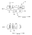
- FIG. 6A to 6C are diagrams for explaining the inspection results when the string gripping portion 125 grips the string 22 without slack and the string 22 is normally attached to the absorbent body 21 of the tampon body 20.
- FIG. 6A is a diagram illustrating a state after the string gripping portion 125 grips the string 22 without slack. At this time, no air is supplied to the moving air cylinder 122, and the holding base 120 and the absorber 21 (outer cylinder member 40) are not in a state of acting to move them to the front end side in the longitudinal direction. is there. At this time, the distance in the longitudinal direction from the opening 125a of the string gripping portion 125 to the central portion of the tampon holding portion 121a is “distance L”.
- the distance from the opening 125a of the string gripping portion 125 to the central portion of the tampon holding portion 121a hardly changes and becomes “distance L + ⁇ l”. That is, as a result of increasing the distance between the tampon holding parts 121a and 121b and the string gripping part 125, the amount of change in the distance becomes a minute amount ⁇ l.
- the tampon holding part 121a is located at a point detected by the sensor 111 before applying tension to the string 22 (state of FIG. 6A). Specifically, before applying tension to the string 22, the sensor 111 is located at a point facing the central portion in the longitudinal direction of the tampon holding portion 121a.
- the tampon holding part 121a is positioned at a point detected by the sensor 111 without changing. More specifically, even after tension is applied to the string 22, the sensor 111 is located at a point facing the substantially central portion of the tampon holding portion 121a in the longitudinal direction. As shown in FIGS. 6B and 6C, the sensor 111 is The tampon holding part 121a can be detected.
- the sensor 111 is an optical sensor.
- the optical sensor irradiates light and blocks the irradiation light, thereby detecting the presence or absence of an object on the optical path of the irradiation light.
- the height of the tampon 10 in the direction intersecting the longitudinal direction of the outer cylinder member 40 is higher than the height of the tampon holding portion 121a.
- the focus of the sensor 111 is set according to the height of the tampon holding part 121a. Therefore, the sensor 111 can detect the presence of the tampon holding part 121a when facing the tampon holding part 121a.
- the control unit of the string inspection unit 109 acquires the detection result of the sensor 111 when the tampon 10 held by the string pulling unit 110 rotated by the rotating drum 108 and the sensor 111 face each other.
- the control unit determines that the string 22 is normally attached to the absorber 21 in the tampon 10 held by the string pulling unit 110.
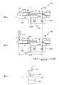
- FIG. 7A to 7C are diagrams for explaining the inspection results when the string 22 is normally attached to the absorber 21, but the string gripping portion 125 loosens the string 22 and grips it.
- FIG. 7A is a diagram showing a state in which the string gripping portion 125 grips the string 22 in a state where the string 22 is loosened, and the holding base 120 and the absorber 21 are still trying to move them to the distal end side in the longitudinal direction. It is a figure which shows the state which the force to do is not working.
- the distance in the longitudinal direction from the opening 125a of the string gripping portion 125 to the central portion of the tampon holding portion 121a is the “distance L” as in FIG. 6A described above. That is, the tampon holding part 121a is located at a point detected by the sensor 111 before the interval between the tampon holding parts 121a and 121b and the string gripping part 125 is increased.
- the distance in the longitudinal direction from the opening 125a of the string gripping portion 125 to the center portion of the tampon holding portion 121a is “distance L + ⁇ ”. That is, as a result of widening the interval between the tampon holding portions 121a and 121b and the string gripping portion 125, the amount of change in the interval becomes “ ⁇ ”.
- the distance in the longitudinal direction from the sensor 111 to the opening 125a of the string gripping portion 125 is set to “distance L”. Therefore, when the absorber 21 moves to the front end side in the longitudinal direction by the distance ⁇ with respect to the string gripping portion 125, as shown in FIG. 7B, the sensor 111 is closer to the rear end side in the longitudinal direction than the center portion of the tampon holding portion 121a. Opposite the position shifted by the distance ⁇ . As a result, as shown in FIG. 7B and FIG. 7C, even after tension is applied to the string 22, the tampon holding part 121 a is located at a point detected by the sensor 111, and the control part is normal to the absorbent body 21. It is judged that it is attached to.
- the string gripping portion 125 may grip the string 22 in a state where the string 22 is slack. Therefore, even if the string 22 is normally attached, the holding base 120 and the absorbent body 21 move toward the front end side in the longitudinal direction as much as the string 22 is slack. Even in this case, the tampon holding part 121a is given a predetermined width in the longitudinal direction so that the sensor 111 can detect the tampon holding part 121a.
- the longitudinal width of the tampon holding portion 121a is “2 ⁇ ”.
- the sensor 111 faces the substantially central portion of the tampon holding portion 121a.
- the sensor 111 is more absorbent than the central portion of the tampon holding portion 121a. Is opposed to the position on the rear end side by the distance moved by (only ⁇ in FIG. 7B).
- the distance ⁇ from the center portion to the rear end portion of the tampon holding portion 121a is the distance that the holding table 120 and the absorber 21 may move by the moving air cylinder 122 when the string 22 is loosely gripped (see FIG. Inside is longer than ⁇ ).
- the sensor 111 can detect the tampon holding part 121a, and the control part can determine that the string 22 is normally attached to the absorber 21.
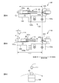
- FIG. 8A to FIG. 8C are diagrams for explaining the test results when the string 22 attached to the absorber 21 is easily cut, that is, when the string 22 is not normally attached to the absorber 21.
- the string 22 is easily cut.
- air is supplied to the moving air cylinder 122, and a force is applied to the holding stand 120 and the absorber 21 to move them to the front end side in the longitudinal direction. It will be cut.
- the sewing of the string of the absorbent body 21 is sweet, the string 22 is removed from the absorbent body 21.
- the string 22 when the string 22 cannot withstand the tensile strength of the force (for example, 60 N) that the piston rod 122 b of the moving air cylinder 122 pushes the holding table 120, the string 22 is cut or removed from the absorber 21. If it does so, the moving force of the holding stand 120 produced by being pushed by the piston rod 122b cannot be suppressed by the tension
- the distance in the longitudinal direction from the opening 125a of the string gripping part 125 to the center part of the tampon holding part 121a increases the distance between the tampon holding parts 121a and 121b and the string gripping part 125 as shown in FIG. While it is “distance L”, after extending the interval, it becomes “distance L + ⁇ ” as shown in FIG. 8B. That is, the amount of change in the distance between the tampon holding part 121a and the string gripping part 125 is “ ⁇ ”.
- the change amount ⁇ of the interval (actually about several centimeters) is larger than the moving distance ( ⁇ in FIG. 7B) of the holding table 120 and the absorbent body when the string 22 is held loosely, and further the center of the tampon holding portion 121a. It is larger than the distance ⁇ from the rear part to the rear part. Therefore, before increasing the distance between the tampon holding parts 121a and 121b and the string gripping part 125, the tampon holding part 121a is located at a point detected by the sensor 111, but after increasing the distance, the tampon holding part 121a is shown in FIGS. 8B and 8C.
- the tampon holding part 121 a is not located at a point detected by the sensor 111, and the sensor 111 faces the outer cylinder member 40 of the tampon 10.
- the focus of the sensor 111 is set in accordance with the height of the tampon holding portion 121a that is higher than the outer cylinder member 40 of the tampon 10. Therefore, when the sensor 111 faces the outer cylinder member 40 of the tampon 10, the sensor 111 detects nothing.
- the control unit of the string inspection unit 109 can determine that the string 22 is not normally attached to the absorbent body 21 when the sensor 111 does not detect the tampon holding part 121a and does not detect anything.
- the sensor 111 Is opposed to the outer cylinder member 40 instead of the tampon holding portion 121a.
- the distance ⁇ from the center portion to the rear end portion of the tampon holding portion 121a is the distance that the holding table 120 and the absorber 21 move by the moving air cylinder 122 when the string 22 is cut or removed from the absorber 21 ( In the figure, it is shorter than ⁇ ).
- the piston of the moving air cylinder 122 is set so that the moving amount ⁇ of the holding table 120 when the string 22 is broken becomes longer than the distance ⁇ from the center portion to the rear end portion of the tampon holding portion 121.
- the extension amount of the rod 122b is adjusted. By doing so, as a result of applying tension to the string 22, when the string 22 breaks or comes off the absorber 21, the sensor 111 faces the outer cylinder member 40, and the control unit applies the string 22 to the absorber 21. It can be determined that is not properly attached.
- FIG. 9A to FIG. 9C are diagrams for explaining the inspection results when the string 22 is not attached to the absorber 21.
- the string 22 cannot be gripped even if the string gripping portion 125 tries to grip the string 22.
- the string gripping portion 125 cannot grip the string 22.
- the string 22 may warp within the moving member 50.
- the string gripping mechanism 123 draws the string 22 between the opening 125a and the tapered part 125b by sucking air from the opening 125a of the string gripping part 125. Therefore, there is a case where the string 22 is prevented from being warped by suction from the opening 125a, and the string gripping portion 125 can grip the string 22.
- the tampon holding part 121a is located at a point detected by the sensor 111, whereas after increasing the distance, FIG. As shown in FIG. 9C, the tampon holding part 121 a is not located at a point detected by the sensor 111.
- the sensor 111 faces the outer cylinder member 40 of the tampon 10 and cannot detect anything.
- the control unit of the string inspection unit 109 determines that the string 22 is not normally attached to the absorber 21 based on the fact that the sensor 111 detects nothing.
- the rear end of the string 22 exposed from the applicator 30 held by the holding table 120 is held by the string holding unit 125, and the holding table 120 and the absorber 21 are connected to the front end in the longitudinal direction.
- a force for moving to the side (side away from the string gripping portion 125) is applied. That is, the interval between the tampon holding parts 121a and 121b and the string gripping part 125 is widened.
- the string gripping portion 125 cannot grip the string 22 or the string 22 is likely to be cut due to the length of the string 22 being short, the holding stand 120 and the absorber are absorbed by the tension of the string 22. The movement of 21 cannot be suppressed. Therefore, the amount of change in the distance between the tampon holding portions 121a and 121b and the string gripping portion 125 corresponds to the amount of extension of the piston rod 122b that pushes the holding stand 120 ( ⁇ in FIGS. 8 and 9).
- the absorber 21 is based on the amount of change in the longitudinal distance between the tampon holding portions 121a and 121b and the string gripping portion 125 before and after the interval between the tampon holding portion 121 and the string gripping portion 125 is widened. It is determined whether or not the string 22 is normally attached. By doing so, the string 22 having a predetermined length is attached to the absorber 21, and the string 22 has a predetermined tensile strength (the force with which the piston rod 122b pushes the holding base 120, the resistance value when the tampon body 20 is removed) ) Can be determined.
- the string 22 can withstand a predetermined tensile strength, and the string 22 is normally attached. I can judge. On the other hand, if the amount of change in the distance between the tampon holding parts 121a and 121b and the string gripping part 125 is larger than the threshold value, the string 22 cannot withstand a predetermined tensile strength, the string 22 is cut, or the string 22 is pulled from the absorber 21. It can be judged that it was removed.
- the tampon 10 determined that the string 22 is normally attached to the absorbent body 21 is supplied to the conveyor belt 113 that continues to the subsequent process as shown in FIG. 4A, and the string 22 is normally attached to the absorbent body 21.
- the tampon 10 determined not to be discharged is discharged out of the manufacturing process as shown in FIG. 4B.
- the distance between the tampon holding parts 121a and 121b and the string gripping part 125 may be widened to inspect the string 22 with tension, and the sensor 111 detects the presence or absence of the tampon holding part 121a and the string 22 is normally It is not limited to determining whether or not it is attached. For example, it may be confirmed whether the string 22 is cut or the string 22 is not detached from the absorber 21 by visual observation.
- the senor 111 may be positioned at a point facing the tampon holding portion 121b on the rear end side. In this case, it is possible to determine whether or not the string 22 has been normally attached based on the presence or absence of the tampon holding portion 121b on the rear end side after the interval is widened. In addition, the sensor 111 detects the tampon 10 when the string 22 is normally attached before and after the interval between the tampon holding parts 121a and 121b and the string gripping part 125 is increased.
- the position of the sensor 111 may be adjusted so that the sensor 111 is located at a point where the tampon 10 is detected. Further, the actual detection of the difference between the position of the tampon holding portions 121a and 121b before increasing the interval between the tampon holding portions 121a and 121b and the string gripping portion 125 and the position of the tampon holding portions 121a and 121b after increasing the interval is actually detected. Then, the change amount of the interval may be calculated to determine whether or not the attachment of the string 22 was normal.
- the force which moves the holding stand 120 (tampon holding part 121a, 121b, the absorber 21) to the longitudinal direction front end is given with respect to the string holding part 125, it is not restricted to this.
- a force for moving the string gripping portion 125 toward the rear end side in the longitudinal direction may be applied to the holding stand 120 (tampon holding portions 121a and 121b).
- the tampon holding parts 121a and 121b correspond to fixed parts
- the string gripping part 125 corresponds to a moving part.
- the sensor 111 before increasing the distance between the tampon holding parts 121a and 121b and the string gripping part 125, the sensor 111 is positioned at a point where the sensor 111 detects the string gripping part 125, and after increasing the distance, the sensor 111 moves the string gripping part 125. It may be determined whether or not the attachment of the string 22 is normal depending on whether or not it is detected.
- the holding table 120 is divided into a first holding table 120 a that holds the tampon 10 and a second holding table 120 b that is connected to the piston rod 122 b of the moving air cylinder 122.
- the first holding table 120a is movable in the longitudinal direction with respect to the second holding table 120b.
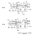
- the load cell 127 which detects compressive force is provided.
- the second holding table 120b acts on the first holding table 120a via the load cell 127 so as to move the first holding table 120a to the front end side in the longitudinal direction.
- the string 22 is normally attached to the absorbent body 21 (FIG. 10A)
- tension is applied to the string 22 and the force that the absorbent body 21 and the first holding stand 120a try to move to the front end side in the longitudinal direction is suppressed. To do.
- the second holding table 120b tries to push the first holding table 120a to the front end side in the longitudinal direction, and the first holding table 120a tries to return to the rear side in the longitudinal direction by the tension of the string 22. Therefore, a compressive force acts on the load cell 127 between the first holding table 120a and the second holding table 120b.
- the string 22 is normally applied to the absorber 21. If it is determined that the strap 22 is attached and a predetermined compressive force does not act on the load cell 127, it may be determined that the string 22 is not normally attached to the absorber 21.
- FIG. 11A and FIG. 11B are diagrams for explaining string tension inspection of the tampon 10 ′ without the applicator 30.
- FIG. 11A is a diagram illustrating the configuration of the string pulling unit 110 ′
- FIG. 11B is a diagram of the state in which the movement of the absorber 21 is regulated as viewed from above.
- the tampon body 20 (the absorbent body 20 and the string 22) has been described with respect to the string tensile inspection of the tampon 10 accommodated in the applicator 30, but in the following, the tampon 10 ′ having the absorbent body 21 and the string 22 That is, the tampon 10 ′ without the applicator 30 will be described.
- the string tension test can be performed on the tampon 10 without the applicator 30 by the inspection apparatus having the same configuration as the string tension unit 110 of FIG. 5A used for the tampon 10 with the applicator 30. However, as shown in FIG. 11, the method for regulating the movement of the absorber 21 is different.
- a front end side tampon holding portion 130 (corresponding to a restricting portion) that restricts the movement of the absorber 21 and a rear end side tampon holding portion 131 (corresponding to a restricting portion) ) Is provided.
- the tip side tampon holding part 130 is composed of a pair of protrusions and a releasable clamp that is spanned between the protrusions.
- the absorber 21 is located between the protrusions of the front end side tampon holding part 130.
- the rear end side tampon holding part 131 is composed of a pair of protrusions, and the string 22 is located between the protrusions.
- the lateral distance between the protrusions of the rear end side tampon holding portion 131 is smaller than the outer diameter of the absorbent body 21, tension is applied to the string 22, and a force for moving the absorbent body 21 toward the rear end side in the longitudinal direction is generated.
- the rear end portion of the absorber 21 comes into contact with the end surface on the front end side of the rear end side tampon holding portion 131. Therefore, the rear end side tampon holding part 131 can restrict the movement of the absorber 21 toward the rear end side in the longitudinal direction.
- the string gripping part 125 grips the string 22 while the suction part 126 sucks air from the rear end side of the absorber 21 (FIG. 5B). Thereafter, air is supplied to the moving air cylinder 122, and a force for moving them to the front end side in the longitudinal direction acts on the holding table 120 and the tampon 10 'held on the holding table 120. In this way, the longitudinal distance between the front end side tampon holding part 130 and the rear end side tampon holding part 131 and the string gripping part 125 is widened to apply tension to the string 22.
- the string 22 has been normally attached based on the amount of change in the distance between the front end tampon holding part 130 and the rear end side tampon holding part 131 and the string gripping part 125 before and after increasing the distance in the longitudinal direction. It is good to judge. If the change amount of the interval is equal to or smaller than the threshold value, it is determined that the string 22 is normally attached. If the change amount of the interval is larger than the threshold value, it can be determined that the string 22 is not normally attached. In addition, as shown in FIG.
- the sensor 111 before increasing the distance between the front end tampon holding portion 130 and the rear end tampon holding portion 131 and the string gripping portion 125, the sensor 111 is placed at a point where the front end tampon holding portion 130 can be detected. It may be determined whether or not the string 22 is normally attached based on the presence or absence of detection of the distal end tampon holding part 130 after being positioned and widened.
- the absorbent body 21 is compressed into a substantially cylindrical shape after the string 22 is attached to the absorbent body material 211 covered with the cover body 212.
- the string 22 is rolled up at the rear end of the absorbent body 21 and individually wrapped.
- the string 22 may be rounded and press-molded when the absorber 21 is compressed. Therefore, as shown in FIG. 11, when the tensile inspection of the string 22 is performed after the absorber 21 is compressed, the rounded string 22 is stretched to perform the tensile inspection, and after the inspection, the process of rounding the string 22 again is performed. There must be.
- the tensile inspection of the string 22 may be performed before the string 22 is attached to the absorbent body 21 before being compressed.
- FIG. 11 by performing a tensile inspection of the string 22 after the absorber 21 is compressed, it is possible to detect a defect due to the string 22 being brazed in the compression process.
- the tampon manufacturing method and the tampon manufacturing apparatus according to the present invention have been described above based on the above embodiment. However, the above-described embodiment of the present invention is for facilitating the understanding of the present invention. The invention is not limited. The present invention can be changed and improved without departing from the gist thereof, and the present invention includes the equivalents thereof.
Landscapes
- Health & Medical Sciences (AREA)
- Engineering & Computer Science (AREA)
- Vascular Medicine (AREA)
- Epidemiology (AREA)
- Biomedical Technology (AREA)
- Heart & Thoracic Surgery (AREA)
- Manufacturing & Machinery (AREA)
- Life Sciences & Earth Sciences (AREA)
- Animal Behavior & Ethology (AREA)
- General Health & Medical Sciences (AREA)
- Public Health (AREA)
- Veterinary Medicine (AREA)
- Absorbent Articles And Supports Therefor (AREA)
Abstract
Description
吸収体に紐を取り付ける際の紐供給部において、紐に結び目や毛玉等の欠陥部が有るか否かを確認し、欠陥部の有る紐が取り付けられたタンポンを製造ラインから排除するタンポンの製造方法が提案されている。(例えば、特許文献1参照)。
本発明の他の特徴については、本明細書及び添付図面の記載により明らかにする。
このようなタンポンの製造方法によれば、吸収体に紐が正常に取り付けられたか否かを検査することが出来る。
このようなタンポンの製造方法によれば、吸収体に紐が正常に取り付けられたか否かを検査することができる。
このようなタンポンの製造方法によれば、吸収体に紐が正常に取り付けられたか否かを判断することが出来る。
このようなタンポンの製造方法によれば、吸収体に対する紐の取り付けが不良である製品を製造工程外へ排出することができ、吸収体に紐が正常に取り付けられた製品を提供することが出来る。
このようなタンポンの製造方法によれば、吸収体に紐が正常に取り付けられたか否かを判断することが出来る。
このようなタンポンの製造方法によれば、吸収体に対する紐の取り付けが不良である製品を検出することが出来る。
このようなタンポンの製造方法によれば、紐が弛んで把持されたとしても、紐の取り付けが正常であれば、紐の取り付けが正常な製品と判断される。
このようなタンポンの製造方法によれば、把持部が紐の弛みを抑えて紐を把持することができる。
このようなタンポンの製造装置によれば、吸収体に紐が正常に取り付けられた製品を提供することが出来る。
先ず、タンポン10の構成について説明する。
図1Aは、タンポン10の構成要素を示す断面図であり、図1Bは、タンポン本体20となる吸収体21に紐22が取り付けられる様子を示す図であり、図1Cは、タンポン本体20の外観図である。なお、以降の説明において、タンポン10の長手方向において、膣腔内に挿入される側を先端と呼び、反対側を後端と呼ぶ。
次に、上述したタンポン10を製造する製造方法について説明する。図2は、タンポンの製造装置100を正面から見た模式図である。図3は、タンポンの製造装置100を上方から見た模式図である。図4は、不良品排出部112の模式図である。なお、タンポン10は、タンポン本体20とアプリケーター30とが別の工程にて製造された後に、組み立てられる。
<紐引張りユニット110>
図5A及び図5Bは、紐引張りユニット110を説明する図である。紐引張りユニット110は、保持台120と、アプリケーター30を介して吸収体21の動きを規制するタンポン保持部121a,121b(規制部に相当)と、移動エアーシリンダー122と、紐把持機構123と、を有する。保持台120上にタンポン10が設けられ、保持台120の上面にタンポン保持部121a,121bが設けられている。保持台120は、移動エアーシリンダー122が有するピストンロッド122bの先端に設けられている。ゆえに、保持台120は、タンポン保持部121a,121bにより保持したタンポン10(アプリケーター30)と共に長手方向に移動可能である。
図2に示す製造工程において、タンポン10は、先端成型ユニット107の後、中継ローラー106を介して、紐引張りユニット110の保持台120に受け渡される。このとき、移動エアーシリンダー122にはエアーが供給されていない。そのため、ピストンロッド122bは延びておらず、図5Aに示すように、保持台120と本体部122aは比較的に近くに位置する。保持台120にタンポン10が受け渡されると、後端側のタンポン保持部121bのクランプが閉じられてタンポン10が保持される。なお、このとき、タンポン本体20は外筒部材40内に収容されており、図1Aに示すように、移動部材50は外筒部材40に対して後端側に突出している。そのため、移動部材50の後端は、紐把持部125の開孔125aの比較的に近くに位置する。
図6Aから図6Cは、紐把持部125が弛みなく紐22を把持し、タンポン本体20の吸収体21に紐22が正常に取り付けられた場合の検査結果を説明する図である。図6Aは、紐把持部125が弛みなく紐22を把持した後の状態を示す図である。この時、移動エアーシリンダー122にエアーは供給されておらず、保持台120及び吸収体21(外筒部材40)に、それらを長手方向先端側へ移動させようとする力が働いていない状態である。この時、紐把持部125の開孔125aからタンポン保持部121aの中央部までの長手方向の距離が「距離L」である。
図10A及び図10Bは、その他の紐引張り検査を説明する図である。前述の紐引張り検査では、紐把持部125と吸収体21との長手方向の間隔を広げる方向に力を与えた結果、紐把持部125と吸収体21の長手方向の相対移動量に基づいて、吸収体21に紐22が正常に取り付けられているか否かを判断するがこれに限らない。図10に示す例では、保持台120が、タンポン10を保持する第1保持台120aと、移動エアーシリンダー122のピストンロッド122bに連結された第2保持台120bとに分割されている。第2保持台120bに対して第1保持台120aは長手方向に移動可能である。そして、第1保持台120aと第2保持台120bの間には、圧縮力を検出するロードセル127が設けられている。
図11A及び図11Bは、アプリケーター30無しのタンポン10’の紐引張り検査を説明する図である。図11Aは、紐引張りユニット110’の構成を示す図であり、図11Bは、吸収体21の動きを規制した状態を上から見た図である。ここまで、タンポン本体20(吸収体20及び紐22)がアプリケーター30内に収容されたタンポン10の紐引張り検査について説明しているが、以下では、吸収体21と紐22を有するタンポン10’、即ち、アプリケーター30無しのタンポン10’について説明する。アプリケーター30有りのタンポン10に対して使用する図5Aの紐引張りユニット110と同じ構成の検査装置にて、アプリケーター30無しのタンポン10に対しても紐引張り検査を実施することが出来る。ただし、図11に示すように、吸収体21の動きを規制する方法が異なる。
以上、上記実施の形態に基づき本発明に係るタンポンの製造方法及びタンポンの製造装置を説明したが、上記した発明の実施の形態は、本発明の理解を容易にするためのものであり、本発明を限定するものではない。本発明は、その趣旨を逸脱することなく、変更、改良され得ると共に、本発明にはその等価物が含まれることはもちろんである。
Claims (9)
- 液体を吸収する吸収体と、
前記吸収体に取り付けられた紐と、
を有するタンポンの製造方法であって、
前記紐を前記吸収体に取り付けることと、
前記吸収体の動きを規制部によって規制することと、
前記紐を把持部によって把持することと、
前記吸収体の長手方向における、前記規制部と前記把持部との間隔を広げて、前記紐に張力を付与することと、
を有することを特徴とするタンポンの製造方法。 - 請求項1に記載のタンポンの製造方法であって、
前記タンポンは、前記吸収体を収容する外筒と、前記外筒内を移動して前記吸収体を前記外筒の先端から押し出す内筒と、を備えるアプリケーターを有し、
前記紐は、前記内筒の後端から露出されており、
前記規制部は、前記アプリケーターの動きを規制するとともに、前記内筒の端面を介して前記吸収体の動きを規制する、
タンポンの製造方法。 - 請求項1または請求項2に記載のタンポンの製造方法であって、
前記間隔を広げる前と後における前記規制部と前記把持部の前記長手方向の間隔の変化量に基づいて、前記吸収体に対する前記紐の取り付け不良を検査する、
タンポンの製造方法。 - 請求項1から請求項3の何れか1項に記載のタンポンの製造方法であって、
前記間隔を広げた結果、前記吸収体に対する前記紐の取り付けが不良である前記タンポンを製造工程外へ排出する不良品排出部を有し、
あるタンポンが前記不良品排出部に到達するタイミングを算出し、
前記あるタンポンの前記吸収体に対する前記紐の取り付けが不良である場合、前記不良品排出部は、算出された前記タイミングにて前記あるタンポンを製造工程外へ排出する、
タンポンの製造方法。 - 請求項1から請求項4の何れか1項に記載のタンポンの製造方法であって、
前記規制部と前記把持部のうちの一方を、位置が固定された固定部とし、
前記規制部と前記把持部のうちの他方を、前記長手方向に移動可能な移動部とし、
前記固定部から前記移動部側に所定の距離を離れた地点にセンサーが位置し、
前記間隔を広げた後の前記センサーの検出結果に基づいて、前記吸収体に対する前記紐の取り付け不良を検査する、
タンポンの製造方法。 - 請求項5に記載のタンポンの製造方法であって、
前記移動部は、前記間隔を広げる前に、前記センサーによって検出される地点に位置し、
前記紐の取り付けが不良である場合には、前記間隔を広げた後に、前記移動部は前記センサーに検出されない地点に位置する、
タンポンの製造方法。 - 請求項5または請求項6に記載のタンポンの製造方法であって、
前記移動部は、前記間隔を広げる前に、前記センサーによって検出される地点に位置し、
正常に前記紐が取り付けられ、前記把持部によって前記紐が弛んで把持された場合には、前記間隔を広げた後に、前記移動部は前記センサーに検出される地点に位置する、
タンポンの製造方法。 - 請求項1から請求項7の何れか1項に記載のタンポンの製造方法であって、
前記吸収体に対して前記紐が延出している側から吸引部により吸気しながら、前記把持部が前記紐を把持する、
タンポンの製造方法。 - 液体を吸収する吸収体と、
前記吸収体に取り付けられた紐と、
を有するタンポンの製造装置であって、
前記紐を前記吸収体に取り付ける取付装置と、
前記吸収体の動きを規制する規制部と、
前記紐を把持する把持部と、
前記吸収体の長手方向における、前記規制部と前記把持部との間隔を広げて、前記紐に張力を付与する検査装置と、
を有することを特徴とするタンポンの製造装置。
Priority Applications (3)
| Application Number | Priority Date | Filing Date | Title |
|---|---|---|---|
| AU2011219149A AU2011219149A1 (en) | 2010-02-23 | 2011-02-17 | Method for producing tampon and apparatus for producing tampon |
| EP11747240.7A EP2540268A4 (en) | 2010-02-23 | 2011-02-17 | METHOD FOR PRODUCING A TAMPON AND DEVICE FOR PRODUCING A TAMPON |
| US13/579,621 US9144519B2 (en) | 2010-02-23 | 2011-02-17 | Method for producing tampon and apparatus for producing tampon |
Applications Claiming Priority (2)
| Application Number | Priority Date | Filing Date | Title |
|---|---|---|---|
| JP2010-037848 | 2010-02-23 | ||
| JP2010037848A JP5427641B2 (ja) | 2010-02-23 | 2010-02-23 | タンポンの製造方法、及び、タンポンの製造装置 |
Publications (1)
| Publication Number | Publication Date |
|---|---|
| WO2011105276A1 true WO2011105276A1 (ja) | 2011-09-01 |
Family
ID=44506689
Family Applications (1)
| Application Number | Title | Priority Date | Filing Date |
|---|---|---|---|
| PCT/JP2011/053355 Ceased WO2011105276A1 (ja) | 2010-02-23 | 2011-02-17 | タンポンの製造方法、及び、タンポンの製造装置 |
Country Status (5)
| Country | Link |
|---|---|
| US (1) | US9144519B2 (ja) |
| EP (1) | EP2540268A4 (ja) |
| JP (1) | JP5427641B2 (ja) |
| AU (1) | AU2011219149A1 (ja) |
| WO (1) | WO2011105276A1 (ja) |
Cited By (2)
| Publication number | Priority date | Publication date | Assignee | Title |
|---|---|---|---|---|
| US20150191857A1 (en) * | 2014-01-06 | 2015-07-09 | Uni-Charm Corporation | Manufacturing apparatus of tampon and manufacturing method of tampon |
| CN112839615A (zh) * | 2018-09-10 | 2021-05-25 | 鲁吉利工程股份公司 | 用于给棉条施放器配备棉条的设备及方法 |
Families Citing this family (9)
| Publication number | Priority date | Publication date | Assignee | Title |
|---|---|---|---|---|
| US9211217B2 (en) * | 2012-10-31 | 2015-12-15 | Kimberly-Clark Worldwide, Inc. | Method of manufacturing tampons by forming a softwind with contact elements |
| HUE067926T2 (hu) * | 2015-12-31 | 2024-11-28 | Johnson And Johnson Gmbh | Eljárás tamponanyag feltekercselésére |
| EP3412264B1 (en) * | 2017-06-07 | 2020-01-29 | Ontex BVBA | System and method for tearing off and rolling up a strip of absorbent fiber sheet |
| CH714846A9 (de) * | 2018-03-29 | 2020-01-15 | Ruggli Projects Ag | Vorrichtung zur Formung von Tampons. |
| CN112998962A (zh) * | 2019-12-19 | 2021-06-22 | 吴静茹 | 旋转压缩卫生棉条装置 |
| CN112998961A (zh) * | 2019-12-19 | 2021-06-22 | 吴静茹 | 牵动式卫生棉条的制造方法 |
| EP4052687B1 (en) * | 2021-03-05 | 2025-05-14 | Ontex BV | Improved apparatus for shaping the introductory end of a tampon and method using such apparatus |
| CH719625A1 (de) * | 2022-04-22 | 2023-10-31 | Ruggli Projects Ag | Vorrichtung zur Formung und/oder Glättung eines Tamponendes. |
| CN115931553A (zh) * | 2022-12-01 | 2023-04-07 | 中轻纸品检验认证有限公司 | 一种定量检测短导管式卫生棉条部件拉伸力的方法 |
Citations (7)
| Publication number | Priority date | Publication date | Assignee | Title |
|---|---|---|---|---|
| JPS53148895A (en) * | 1977-06-01 | 1978-12-25 | Mitsubishi Heavy Ind Ltd | Device for making sanitary tampon |
| JPS57173054A (en) * | 1981-04-17 | 1982-10-25 | Kao Corp | Tampon producing method and apparatus |
| JPS60116350A (ja) * | 1983-11-28 | 1985-06-22 | 花王株式会社 | タンポンのひもの插入方法 |
| JPS62286460A (ja) * | 1986-06-05 | 1987-12-12 | 三菱重工業株式会社 | 吸収体圧縮成形装置 |
| JPS63154175A (ja) * | 1986-12-19 | 1988-06-27 | ライオン株式会社 | タンポン製造装置 |
| JP2000042031A (ja) | 1998-07-30 | 2000-02-15 | Lion Corp | 紐付き製品の製造方法及び製造装置 |
| JP2006527640A (ja) * | 2003-06-30 | 2006-12-07 | ザ プロクター アンド ギャンブル カンパニー | ひもを取り付ける方法及び装置 |
Family Cites Families (16)
| Publication number | Priority date | Publication date | Assignee | Title |
|---|---|---|---|---|
| US2361783A (en) * | 1942-10-23 | 1944-10-31 | Tampax Inc | Method of and apparatus for assembling plugs in applicators |
| US2462178A (en) * | 1944-01-13 | 1949-02-22 | Personal Products Corp | Tampon machine and method for making tampons |
| US2532438A (en) * | 1947-04-15 | 1950-12-05 | Sanitary Tampon Corp | Process for severing of connected tampons |
| US2624078A (en) | 1947-08-08 | 1953-01-06 | Sanitary Tampon Corp | Machine for compressing and assembling tampons |
| US2690598A (en) * | 1949-05-16 | 1954-10-05 | Int Cellucotton Products | Tampon and tampon applicator assembling method |
| NL142325B (nl) * | 1964-10-22 | 1974-06-17 | Hahn Carl Dr Kg | Werkwijze en inrichting voor het opwikkelen en aandrukken van het overhangende einde van een terugtrekdraad tegen een einde van een wattenwikkel voor tampons, in het bijzonder menstruatietampons. |
| US4019226A (en) * | 1972-08-10 | 1977-04-26 | Jex Co., Ltd. | Apparatus for automatically shaping cellulose type menstrual tampons |
| DE2355962B1 (ja) | 1973-11-09 | 1975-02-06 | Vereinigte Papierwerke Schickedanz & Co, 8500 Nuernberg | |
| US4836587A (en) | 1987-12-23 | 1989-06-06 | Hauni Richmond, Inc. | Apparatus for making knots in drawstrings of catamenial tampons |
| US5084038A (en) * | 1989-09-12 | 1992-01-28 | Kimberly-Clark Corporation | Apparatus and a method for forming tampons and the tampon itself |
| AU2382695A (en) * | 1994-04-11 | 1995-10-30 | Tambrands Inc. | Method of attaching a tampon withdrawal cord |
| US6585300B1 (en) * | 2001-12-28 | 2003-07-01 | Kimberly-Clark Worldwide, Inc. | Apparatus for applying string to tampon pledgets |
| JP4134052B2 (ja) * | 2005-01-19 | 2008-08-13 | 株式会社 ハリーズ | 生理用タンポンの製造方法及び製造装置 |
| JP4949691B2 (ja) * | 2006-02-01 | 2012-06-13 | ユニ・チャーム株式会社 | シート状構造体の製造システム及び製造方法 |
| JP4949690B2 (ja) | 2006-02-01 | 2012-06-13 | ユニ・チャーム株式会社 | シート状構造体の製造システム及び製造方法 |
| JP5150465B2 (ja) * | 2008-11-21 | 2013-02-20 | ユニ・チャーム株式会社 | タンポンの検査装置、及び、タンポンの検査方法 |
-
2010
- 2010-02-23 JP JP2010037848A patent/JP5427641B2/ja not_active Expired - Fee Related
-
2011
- 2011-02-17 WO PCT/JP2011/053355 patent/WO2011105276A1/ja not_active Ceased
- 2011-02-17 US US13/579,621 patent/US9144519B2/en not_active Expired - Fee Related
- 2011-02-17 AU AU2011219149A patent/AU2011219149A1/en not_active Abandoned
- 2011-02-17 EP EP11747240.7A patent/EP2540268A4/en not_active Withdrawn
Patent Citations (7)
| Publication number | Priority date | Publication date | Assignee | Title |
|---|---|---|---|---|
| JPS53148895A (en) * | 1977-06-01 | 1978-12-25 | Mitsubishi Heavy Ind Ltd | Device for making sanitary tampon |
| JPS57173054A (en) * | 1981-04-17 | 1982-10-25 | Kao Corp | Tampon producing method and apparatus |
| JPS60116350A (ja) * | 1983-11-28 | 1985-06-22 | 花王株式会社 | タンポンのひもの插入方法 |
| JPS62286460A (ja) * | 1986-06-05 | 1987-12-12 | 三菱重工業株式会社 | 吸収体圧縮成形装置 |
| JPS63154175A (ja) * | 1986-12-19 | 1988-06-27 | ライオン株式会社 | タンポン製造装置 |
| JP2000042031A (ja) | 1998-07-30 | 2000-02-15 | Lion Corp | 紐付き製品の製造方法及び製造装置 |
| JP2006527640A (ja) * | 2003-06-30 | 2006-12-07 | ザ プロクター アンド ギャンブル カンパニー | ひもを取り付ける方法及び装置 |
Non-Patent Citations (1)
| Title |
|---|
| See also references of EP2540268A4 * |
Cited By (3)
| Publication number | Priority date | Publication date | Assignee | Title |
|---|---|---|---|---|
| US20150191857A1 (en) * | 2014-01-06 | 2015-07-09 | Uni-Charm Corporation | Manufacturing apparatus of tampon and manufacturing method of tampon |
| CN112839615A (zh) * | 2018-09-10 | 2021-05-25 | 鲁吉利工程股份公司 | 用于给棉条施放器配备棉条的设备及方法 |
| CN112839615B (zh) * | 2018-09-10 | 2024-01-02 | 鲁吉利工程股份公司 | 用于给棉条施放器配备棉条的设备及方法 |
Also Published As
| Publication number | Publication date |
|---|---|
| EP2540268A4 (en) | 2014-03-26 |
| US9144519B2 (en) | 2015-09-29 |
| JP2011172667A (ja) | 2011-09-08 |
| AU2011219149A1 (en) | 2012-09-13 |
| US20130036584A1 (en) | 2013-02-14 |
| JP5427641B2 (ja) | 2014-02-26 |
| EP2540268A1 (en) | 2013-01-02 |
Similar Documents
| Publication | Publication Date | Title |
|---|---|---|
| JP5427641B2 (ja) | タンポンの製造方法、及び、タンポンの製造装置 | |
| JP6180809B2 (ja) | エアジェット紡績機およびその作動方法 | |
| EP2573232A2 (en) | Apparatus for joining a yarn, and yarn winding machine and unit including same | |
| US7269936B2 (en) | Spinning device and method for detecting fiber accumulated state | |
| EP2573023B1 (en) | Yarn winding machine and yarn winding unit | |
| EP2690394A1 (en) | Yarn monitoring device and yarn winding unit | |
| EP2351547B1 (en) | Device for inspecting tampons and method for inspecting tampons | |
| EP3524556A1 (en) | Air spinning machine and air spinning method | |
| CN102161451A (zh) | 纱线卷绕机 | |
| EP2905249B1 (en) | Bobbin setting device and yarn winding machine | |
| EP2907780B1 (en) | Bobbin setting device and yarn winding machine | |
| EP2966022B1 (en) | Yarn winding machine and yarn winding method | |
| EP3075890B1 (en) | Draft device and spinning machine | |
| CN105253710B (zh) | 纱线卷绕机及纱线卷绕方法 | |
| EP3025996A1 (en) | Yarn joining device, yarn winding machine, and yarn joining method | |
| EP2573025A2 (en) | Spinning machine | |
| EP2949793B1 (en) | Spinning machine and spinning method | |
| US20150191857A1 (en) | Manufacturing apparatus of tampon and manufacturing method of tampon | |
| JP2012040159A (ja) | バルーン保持装置およびバルーン検査装置 | |
| JP2014234309A (ja) | 糸継装置、巻取ユニット、繊維機械及び糸継方法 | |
| JP2015020887A (ja) | 解舒補助装置及び自動ワインダ | |
| CN104514058B (zh) | 纤维机械的作业台车 | |
| JP2000042031A (ja) | 紐付き製品の製造方法及び製造装置 | |
| EP2862825B1 (en) | Winding device and yarn winding machine including the same | |
| CN105274664A (zh) | 芯纱供给单元、芯纱供给装置、纺纱机及芯纱供给方法 |
Legal Events
| Date | Code | Title | Description |
|---|---|---|---|
| 121 | Ep: the epo has been informed by wipo that ep was designated in this application |
Ref document number: 11747240 Country of ref document: EP Kind code of ref document: A1 |
|
| WWE | Wipo information: entry into national phase |
Ref document number: 2011219149 Country of ref document: AU |
|
| NENP | Non-entry into the national phase |
Ref country code: DE |
|
| ENP | Entry into the national phase |
Ref document number: 2011219149 Country of ref document: AU Date of ref document: 20110217 Kind code of ref document: A |
|
| WWE | Wipo information: entry into national phase |
Ref document number: 2011747240 Country of ref document: EP |
|
| WWE | Wipo information: entry into national phase |
Ref document number: 13579621 Country of ref document: US |