WO2011105338A1 - バルブシート - Google Patents
バルブシート Download PDFInfo
- Publication number
- WO2011105338A1 WO2011105338A1 PCT/JP2011/053744 JP2011053744W WO2011105338A1 WO 2011105338 A1 WO2011105338 A1 WO 2011105338A1 JP 2011053744 W JP2011053744 W JP 2011053744W WO 2011105338 A1 WO2011105338 A1 WO 2011105338A1
- Authority
- WO
- WIPO (PCT)
- Prior art keywords
- valve seat
- solid lubricant
- iron
- lubricant
- volume
- Prior art date
- Legal status (The legal status is an assumption and is not a legal conclusion. Google has not performed a legal analysis and makes no representation as to the accuracy of the status listed.)
- Ceased
Links
Images


Classifications
-
- F—MECHANICAL ENGINEERING; LIGHTING; HEATING; WEAPONS; BLASTING
- F01—MACHINES OR ENGINES IN GENERAL; ENGINE PLANTS IN GENERAL; STEAM ENGINES
- F01L—CYCLICALLY OPERATING VALVES FOR MACHINES OR ENGINES
- F01L3/00—Lift-valve, i.e. cut-off apparatus with closure members having at least a component of their opening and closing motion perpendicular to the closing faces; Parts or accessories thereof
- F01L3/02—Selecting particular materials for valve-members or valve-seats; Valve-members or valve-seats composed of two or more materials
-
- B—PERFORMING OPERATIONS; TRANSPORTING
- B22—CASTING; POWDER METALLURGY
- B22F—WORKING METALLIC POWDER; MANUFACTURE OF ARTICLES FROM METALLIC POWDER; MAKING METALLIC POWDER; APPARATUS OR DEVICES SPECIALLY ADAPTED FOR METALLIC POWDER
- B22F1/00—Metallic powder; Treatment of metallic powder, e.g. to facilitate working or to improve properties
- B22F1/10—Metallic powder containing lubricating or binding agents; Metallic powder containing organic material
- B22F1/103—Metallic powder containing lubricating or binding agents; Metallic powder containing organic material containing an organic binding agent comprising a mixture of, or obtained by reaction of, two or more components other than a solvent or a lubricating agent
-
- C—CHEMISTRY; METALLURGY
- C22—METALLURGY; FERROUS OR NON-FERROUS ALLOYS; TREATMENT OF ALLOYS OR NON-FERROUS METALS
- C22C—ALLOYS
- C22C27/00—Alloys based on rhenium or a refractory metal not mentioned in groups C22C14/00 or C22C16/00
- C22C27/04—Alloys based on tungsten or molybdenum
-
- C—CHEMISTRY; METALLURGY
- C22—METALLURGY; FERROUS OR NON-FERROUS ALLOYS; TREATMENT OF ALLOYS OR NON-FERROUS METALS
- C22C—ALLOYS
- C22C33/00—Making ferrous alloys
- C22C33/02—Making ferrous alloys by powder metallurgy
-
- C—CHEMISTRY; METALLURGY
- C22—METALLURGY; FERROUS OR NON-FERROUS ALLOYS; TREATMENT OF ALLOYS OR NON-FERROUS METALS
- C22C—ALLOYS
- C22C38/00—Ferrous alloys, e.g. steel alloys
- C22C38/02—Ferrous alloys, e.g. steel alloys containing silicon
-
- C—CHEMISTRY; METALLURGY
- C22—METALLURGY; FERROUS OR NON-FERROUS ALLOYS; TREATMENT OF ALLOYS OR NON-FERROUS METALS
- C22C—ALLOYS
- C22C38/00—Ferrous alloys, e.g. steel alloys
- C22C38/12—Ferrous alloys, e.g. steel alloys containing tungsten, tantalum, molybdenum, vanadium, or niobium
-
- C—CHEMISTRY; METALLURGY
- C22—METALLURGY; FERROUS OR NON-FERROUS ALLOYS; TREATMENT OF ALLOYS OR NON-FERROUS METALS
- C22C—ALLOYS
- C22C38/00—Ferrous alloys, e.g. steel alloys
- C22C38/16—Ferrous alloys, e.g. steel alloys containing copper
-
- F—MECHANICAL ENGINEERING; LIGHTING; HEATING; WEAPONS; BLASTING
- F01—MACHINES OR ENGINES IN GENERAL; ENGINE PLANTS IN GENERAL; STEAM ENGINES
- F01L—CYCLICALLY OPERATING VALVES FOR MACHINES OR ENGINES
- F01L3/00—Lift-valve, i.e. cut-off apparatus with closure members having at least a component of their opening and closing motion perpendicular to the closing faces; Parts or accessories thereof
- F01L3/22—Valve-seats not provided for in preceding subgroups of this group; Fixing of valve-seats
-
- F—MECHANICAL ENGINEERING; LIGHTING; HEATING; WEAPONS; BLASTING
- F01—MACHINES OR ENGINES IN GENERAL; ENGINE PLANTS IN GENERAL; STEAM ENGINES
- F01L—CYCLICALLY OPERATING VALVES FOR MACHINES OR ENGINES
- F01L2301/00—Using particular materials
-
- F—MECHANICAL ENGINEERING; LIGHTING; HEATING; WEAPONS; BLASTING
- F01—MACHINES OR ENGINES IN GENERAL; ENGINE PLANTS IN GENERAL; STEAM ENGINES
- F01L—CYCLICALLY OPERATING VALVES FOR MACHINES OR ENGINES
- F01L2303/00—Manufacturing of components used in valve arrangements
Definitions
- the present invention relates to a valve seat for an internal combustion engine, and more particularly to a valve seat made of an iron-based composite sintered alloy that is used under lean conditions in a lubricated state by in-cylinder fuel injection.
- valve seats which are the seats of the intake and exhaust valves and have the function of keeping the combustion chamber secret, are also exposed to the combustion pressure and are repeatedly subjected to the impact of repeated movement of the valves, so they are resistant to wear in special environments. Need. In particular, in an in-cylinder fuel injection type internal combustion engine that directly injects fuel into each cylinder (cylinder bore), the fuel does not pass between the valve and the valve seat. Cooling contributes to a high temperature environment.
- valve seat for an in-cylinder fuel-injection internal combustion engine that is, as a valve seat used in a high-temperature environment with severe lubrication conditions, for example, as disclosed in Japanese Patent Laid-Open No. 2003-166025, Gold that has been combined with a solid lubricant to improve self-lubricating properties, and high-alloy materials that have improved wear resistance in high-temperature environments have been used.
- valve seat requires tight finishing accuracy on the surface in contact with the valve in order to ensure airtightness in the combustion chamber. Also, since it is coaxially processed with the valve guide after assembly to the cylinder, excellent machinability is required. It is done. However, compared to other members that make up the engine, the presence of high-hardness particles added to improve wear resistance and so-called intermittent cutting due to the presence of voids (holes) inside the sintered alloy When combined, the valve seat has become a difficult-to-cut material and is a factor that reduces the productivity of the engine production line. Therefore, the valve seat is required to improve not only wear resistance but also machinability.
- the present invention is an iron-based composite firing having high wear resistance and good machinability that can be used for an in-cylinder fuel injection type internal combustion engine corresponding to improvement in fuel consumption, low emission, and high output. It is an object to provide a bonded gold valve seat.
- the present invention basically uses a solid lubricant, but as described above, it is used in such a form that the strength of the sintered body does not decrease even when a predetermined amount or more of the solid lubricant is combined.
- the inventors of the present invention specifically provided self-lubricating properties by dispersing a relatively coarse solid lubricant in an amount that does not significantly reduce the strength of the sintered body. It was conceived that the machinability can be improved by dispersing a fine solid lubricant at a level that does not hinder the bonding of steel.
- the valve seat of the present invention is a valve seat made of an iron-based composite sintered alloy in which hard particles and a solid lubricant are dispersed, wherein the solid lubricant is a coarse lubricant having an average particle size of at least 20 to 100 ⁇ m. It consists of solid lubricants with average particle diameters of 2 to 10 ⁇ m and different average particle diameters, and the dispersion amount of the coarse lubricant and fine lubricant is 0.3% by volume or more, respectively, and the total is 10% by volume or less. It is characterized by that. The total amount is preferably 1 to 5% by volume.
- 90% or more of fine lubricants having an average particle diameter of 2 to 10 ⁇ m are 0.5 to 15 ⁇ m
- 90% or more of coarse lubricants having an average particle diameter of 20 to 100 ⁇ m are 10 to 120 ⁇ m.
- the particle size constituting the matrix at that time is preferably an average particle size of 45 to 150 ⁇ m.
- the solid lubricant used for the valve seat of the present invention was selected from the group consisting of fluoride (LiF, CaF 2 and BaF 2 etc.), sulfide (MnS, MnS 2 etc.) and boron nitride (BN). At least one solid lubricant is preferred. That is, the above-described coarse and fine lubricants may be selected from the same kind of, for example, CaF 2 alone or from different solid lubricants such as CaF 2 and BN.
- the hard particles used in the valve seat of the present invention have an average particle size of 40 to 70% Mo, 0.4 to 2.0% Si, 0.1% or less C, and the balance consisting of Fe and inevitable impurities. 20-60 ⁇ m Fe—Mo—Si alloy particles are preferred.
- the dispersion amount of the hard particles is preferably 0.3 to 5% by volume, and more preferably 0.5 to 2% by volume.
- the matrix of the valve seat of the present invention is 0.4 to 2.0% Si, 0.5 to 5% Mo, 1 to 5% Cu, 0.5 to 2.5% C, and the balance is Fe and inevitable impurities. Preferably it consists of. Further, the structure is more preferably composed of a martensite phase and / or a pearlite phase.
- the valve seat of the present invention provides a self-lubricating property by dispersing a relatively coarse solid lubricant in an amount that does not significantly reduce the strength of the sintered body, and does not inhibit the bonding between matrix particles. Since the machinability is improved by dispersing the solid lubricant, it is possible to achieve both wear resistance and machinability. Therefore, as a valve seat used in an in-cylinder fuel injection type internal combustion engine, excellent durability is exhibited even when used under a lean condition and in a wide temperature range. In particular, it can be more preferably applied as an intake valve seat.
- the valve seat made of an iron-based composite sintered alloy according to the present invention includes a matrix, a solid lubricant dispersed in the matrix, and hard particles, and the solid lubricant has a coarse lubricant having an average particle size of at least 20 to 100 ⁇ m. It consists of a solid lubricant having a different average particle diameter from a fine lubricant with an average particle diameter of 2 to 10 ⁇ m, and the dispersion amount of the coarse lubricant and the fine lubricant is 0.3 volume% or more, and a total of 10 volume% or less. It is characterized by doing. If the coarse-grained lubricant is less than 20 ⁇ m in average particle size, it is difficult to improve self-lubricating properties.
- the fine lubricant is less than 2 ⁇ m in average particle size, the lubricants aggregate together making it difficult to finely disperse. If the average particle size exceeds 10 ⁇ m, the ratio of coarse lubricant is increased rather than improving machinability. As a result, the strength is lowered, which is not preferable. Also, if the dispersion amount of coarse and fine lubricants is less than 0.3% by volume, sufficient self-lubrication and machinability will not be provided. If the total amount exceeds 10% by volume, the bond strength between the particles will be increased. This is not preferable because the wear resistance is lowered due to drop of particles and the like.
- the dispersion amount of the solid lubricant is more preferably 1 to 5% by volume.
- the solid lubricant used for the valve seat of the present invention was selected from the group consisting of fluoride (LiF, CaF 2 and BaF 2 etc.), sulfide (MnS, MnS 2 etc.) and boron nitride (BN). At least one solid lubricant is preferred. That is, the above-mentioned fine lubricant and coarse lubricant may be selected from the same type, for example, CaF 2 alone, or may be selected from different solid lubricants such as CaF 2 and BN. A particularly preferred combination of solid lubricants includes CaF 2 as a coarse lubricant and MnS as a fine lubricant.
- the peak position of the particle size distribution is 2 to 10 ⁇ m and 20 to 100 ⁇ m, respectively, the peak position is the average particle diameter.
- the hard particles used in the valve seat of the present invention are 40% to 70% Mo by mass, 0.4% to 2.0% Si, 0.1% or less C, and the balance is Fe and inevitable impurities. It is preferable to use Fe—Mo—Si alloy particles. Fe-Mo-Si alloy particles have little diffusion into the iron-based matrix and do not cause the matrix to be altered, so that the opponent attack due to the matrix alteration is suppressed and the wear resistance is improved.
- the hard particles preferably have a Vickers hardness of 600 to 1200 Hv and an average particle diameter of 20 to 60 ⁇ m from the viewpoint of wear resistance and fracture toughness. Further, 90% or more of the hard particles having an average particle diameter of 20 to 60 ⁇ m are preferably 5 to 150 ⁇ m.
- the dispersion amount of the hard particles is preferably 0.3 to 5% by volume, more preferably 0.5 to 2% by volume from the viewpoint of wear resistance and machinability.
- the composition of the matrix is 0.4% to 2.0% Si, 0.5% to 5% Mo, 1% to 5% Cu, 0.5% to 2.5% C, and the balance is Fe and inevitable impurities.
- Si is contained in the matrix and hard particles, forming an oxide film to improve wear resistance
- Mo is an element improving hardenability and matrix strength and improving wear resistance
- Cu is contained in the matrix It is an element that improves its hardness, strength, and thermal conductivity to improve wear resistance, while also improving self-lubricating properties due to its soft metal characteristics.
- C has the effect of strengthening by dissolving in the matrix, it combines with other alloy elements to form carbides and improve wear resistance.
- metal powder of each alloy element, graphite powder, or the like may be added to iron powder, or alloy powder (prealloy alloy powder) alloyed in advance with a predetermined composition may be used.
- Fe-Mo-Si alloy powder containing 2.5% Mo and 1% Si by mass% is preferably used.
- the valve seat of the present invention is obtained by press molding, sintering, and heat treatment from a mixed powder obtained by mixing and mixing a predetermined amount of various raw material powders constituting the matrix, solid lubricant, and hard particles described above. .
- stearate or the like may be added to the raw material powder as a release agent for press molding.
- Sintering is performed in a temperature range of 1050 to 1200 ° C. in a vacuum or non-oxidizing (reducing) atmosphere. Further, the tempering heat treatment is performed in a temperature range of 500 to 700 ° C. When the sintering temperature is less than 1050 ° C., diffusion bonding is insufficient and a predetermined strength cannot be obtained.
- the temperature exceeds 1200 ° C.
- abnormal diffusion occurs between the hard particles and the matrix, resulting in deterioration of wear resistance.
- an atmosphere in which NH 3 or a mixed gas of N 2 and H 2 is introduced is preferable.
- the pores of the sintered body may be sealed with a resin or the like.
- the amount of dispersion of the solid lubricant and hard particles defined as the feature is expressed by volume%. Since these volume% is statistically the same value as the area% in the cross section of the sintered body, it can be measured by image analysis of the structure photograph using an optical microscope or a scanning electron microscope of the cross section of the sintered body. However, since the sintered body of the present invention contains voids (voids), the volume% shown in the present invention is measured with the region excluding voids as 100%.
- Examples 1 to 8 (J1 to J8) and Comparative Examples 1 to 6 (H1 to H6) Prealloy alloy powder (Fe-2.5 mass% Mo-1.0 mass% Si alloy powder) having a peak at 75-100 ⁇ m in particle size distribution, electrolytic Cu powder, solid lubricant powder (CaF 2 with an average particle size of 35 ⁇ m, average particle size) 5 ⁇ m MnS, hexagonal BN with an average particle size of 7 ⁇ m, hexagonal BN with an average particle size of 55 ⁇ m, hard particle powder (average particle size 45 ⁇ m, Fe-60 mass% Mo-1 mass% Si ferromolybdenum silicon powder), The graphite powder was mixed and kneaded with the formulation shown in Table 1.
- the obtained sintered body was polished, and the structure was observed with an optical microscope or a scanning electron microscope.
- the structure was identified using elemental analysis as necessary, and volume% of the solid lubricant and hard particles were measured by image analysis. However, the volume% of the solid lubricant and the hard particles was calculated assuming that the area excluding the internal voids (voids) was 100%. Within the scope of the present invention, voids were in the range of 7-12% by volume. Etching was also used to observe the matrix structure.
- the image analysis was performed using a tissue photograph at a magnification of 100 times. The results are shown in Table 2.
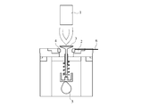
- the obtained sintered body was processed into a valve seat, and the wear resistance was evaluated using a single wear tester shown in FIG.
- the valve seat 4 is press-fitted into the cylinder head equivalent material 2 and set in a testing machine, and the valve 3 is moved up and down in conjunction with the rotation of the cam 5 while the valve 3 and the valve seat 4 are heated by the burner 1. Is done by letting A thermocouple 6 is embedded in the valve seat 4, and the burner 1 is adjusted so that the contact surface of the valve seat has a predetermined temperature.
- the valve seat 4 is worn by being repeatedly hit by the valve 3. The amount of wear was calculated by measuring the shape of the valve seat and the valve before and after the test.
- valve made of SUH alloy JIS standard: JIS G 4311
- the test conditions were temperature (surface per valve seat) 150 ° C. and 250 ° C., cam rotation speed 2500 rpm, and test time 5 hours.
- the test results are shown in Table 3, FIG. 1 (a) (test temperature 150 ° C.), and FIG. 1 (b) (test temperature 250 ° C.).
- Examples 1 to 8 according to the present invention have a valve seat wear of 15 to 29 ⁇ m at a test temperature of 150 ° C., a valve wear of the counterpart material of 5.3 to 9 ⁇ m, and a valve seat wear of 20.4 to 31.2 ⁇ m at a test temperature of 250 ° C. There was also a valve wear amount of 2.5 to 6.3 ⁇ m, and both showed excellent wear resistance and low attack on the mating material.
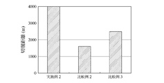
- Example 2 and Comparative Examples 2 and 3 a large amount of a ring-shaped sintered body is manufactured, and end face processing is performed using a lathe while moving the cutting tool from the outer peripheral side to the inner peripheral side of the end face.
- machinability was evaluated.
- the test conditions were a rotation speed of 730 rpm, a cutting depth of 0.3 mm, a feed of 0.05 mm / rev, and a dry type (dry), and a carbide tool was used as the cutting tool.
- the machinability was evaluated by the cutting distance with respect to a predetermined tool wear amount and the surface roughness of the machined surface. The test results are shown in FIG.
- Example 2 of the present invention the cutting distance until the flank wear amount of the tool reached a predetermined wear amount was 4000 m or more.
- the comparative example 2 of the conventional material in which only the coarse lubricant was dispersed was 1600 m, and even if the fine lubricant was added, the comparative example 3 of 0.2 vol% was 2500 m.
- Example 2 of the present invention was a better result than Comparative Examples 2 and 3.
Landscapes
- Chemical & Material Sciences (AREA)
- Engineering & Computer Science (AREA)
- Mechanical Engineering (AREA)
- Materials Engineering (AREA)
- Metallurgy (AREA)
- Organic Chemistry (AREA)
- General Engineering & Computer Science (AREA)
- Chemical Kinetics & Catalysis (AREA)
- Powder Metallurgy (AREA)
Abstract
Description
粒度分布上、75~100μmにピークを有するプレアロイ合金粉末(Fe-2.5質量%Mo-1.0質量%Si合金粉末)に電解Cu粉末、固体潤滑材粉末(平均粒径35μmのCaF2、平均粒径5μmのMnS、平均粒径7μmの六方晶BN、平均粒径55μmの六方晶BN)、硬質粒子粉末(平均粒径45μm、Fe-60質量%Mo-1質量%Siのフェロモリブデンシリコン粉末)、及び黒鉛粉末を表1に示す配合で、混合、混練した。これらの混合粉を金型に充填し、成形プレスにより圧縮成形した後、1120℃で真空雰囲気にて焼結し、外径37.6mmφ、内径26mmφ、厚さ8mmのリング状焼結体を得た。その後、650℃で焼戻熱処理を行った。なお、表1に示す配合割合は、全て質量%である。


Claims (6)
- 硬質粒子及び固体潤滑材を分散させた鉄基複合焼結合金製バルブシートであって、前記固体潤滑材が少なくとも平均粒径20~100μmの粗粒潤滑材と平均粒径2~10μmの微粒潤滑材の平均粒径の異なる固体潤滑材からなり、前記粗粒潤滑材と前記微粒潤滑材の分散量がそれぞれ0.3体積%以上、合計で10体積%以下とすることを特徴とする鉄基複合焼結合金製バルブシート。
- 前記固体潤滑材が、フッ化物、硫化物及び窒化硼素からなる群より選択された少なくとも一種の固体潤滑材であり、且つ前記固体潤滑材の分散量が1~5体積%であることを特徴とする請求項1に記載の鉄基複合焼結合金製バルブシート。
- 前記硬質粒子が、質量%で40~70%のMo、0.4~2.0%のSi、0.1%以下のC、並びに残部がFe及び不可避的不純物からなる平均粒径20~60μmのFe-Mo-Si合金粒子であり、且つ前記硬質粒子の分散量が0.3~5体積%であることを特徴とする請求項1又は2に記載の鉄基複合焼結合金製バルブシート。
- 前記硬質粒子の分散量が0.5~2.0体積%であることを特徴とする請求項3に記載の鉄基複合焼結合金製バルブシート。
- 前記硬質粒子及び前記固体潤滑材が分散するマトリックスが、質量%で0.4~2.0%のSi、0.5~5%のMo、1~5%のCu、0.5~2.5%のC、並びに残部がFe及び不可避的不純物からなることを特徴とする請求項1乃至4の何れかに記載の鉄基複合焼結合金製バルブシート。
- 前記マトリックスが、マルテンサイト相及び/又はパーライト相からなることを特徴とする請求項5に記載の鉄基複合焼結合金製バルブシート。
Priority Applications (3)
| Application Number | Priority Date | Filing Date | Title |
|---|---|---|---|
| US13/580,499 US8844903B2 (en) | 2010-02-23 | 2011-02-21 | Valve seat |
| EP11747299.3A EP2540852B1 (en) | 2010-02-23 | 2011-02-21 | Valve seat |
| CN201180010500.8A CN102762755B (zh) | 2010-02-23 | 2011-02-21 | 阀座 |
Applications Claiming Priority (2)
| Application Number | Priority Date | Filing Date | Title |
|---|---|---|---|
| JP2010037386A JP5649830B2 (ja) | 2010-02-23 | 2010-02-23 | バルブシート |
| JP2010-037386 | 2010-02-23 |
Publications (1)
| Publication Number | Publication Date |
|---|---|
| WO2011105338A1 true WO2011105338A1 (ja) | 2011-09-01 |
Family
ID=44506746
Family Applications (1)
| Application Number | Title | Priority Date | Filing Date |
|---|---|---|---|
| PCT/JP2011/053744 Ceased WO2011105338A1 (ja) | 2010-02-23 | 2011-02-21 | バルブシート |
Country Status (5)
| Country | Link |
|---|---|
| US (1) | US8844903B2 (ja) |
| EP (1) | EP2540852B1 (ja) |
| JP (1) | JP5649830B2 (ja) |
| CN (1) | CN102762755B (ja) |
| WO (1) | WO2011105338A1 (ja) |
Cited By (1)
| Publication number | Priority date | Publication date | Assignee | Title |
|---|---|---|---|---|
| WO2014007278A1 (ja) * | 2012-07-06 | 2014-01-09 | 株式会社リケン | 鉄基焼結合金製バルブシート |
Families Citing this family (8)
| Publication number | Priority date | Publication date | Assignee | Title |
|---|---|---|---|---|
| US9291291B2 (en) | 2013-05-23 | 2016-03-22 | Ti Group Automotive Systems, Llc | Tube fitting with integrated seal |
| JP5658804B1 (ja) * | 2013-07-26 | 2015-01-28 | 株式会社リケン | 焼結合金製バルブガイド及びその製造方法 |
| JP5887374B2 (ja) | 2014-03-19 | 2016-03-16 | 株式会社リケン | 鉄基焼結合金製バルブシート |
| US10391557B2 (en) | 2016-05-26 | 2019-08-27 | Kennametal Inc. | Cladded articles and applications thereof |
| WO2018179590A1 (ja) * | 2017-03-28 | 2018-10-04 | 株式会社リケン | 焼結バルブシート |
| US10344757B1 (en) | 2018-01-19 | 2019-07-09 | Kennametal Inc. | Valve seats and valve assemblies for fluid end applications |
| US11566718B2 (en) | 2018-08-31 | 2023-01-31 | Kennametal Inc. | Valves, valve assemblies and applications thereof |
| CN112410780B (zh) * | 2020-11-17 | 2021-08-20 | 安庆帝伯粉末冶金有限公司 | 一种激光熔覆气门座圈及其制造方法 |
Citations (6)
| Publication number | Priority date | Publication date | Assignee | Title |
|---|---|---|---|---|
| JPH06145916A (ja) * | 1992-10-30 | 1994-05-27 | Nippon Piston Ring Co Ltd | 鉄系焼結合金およびその製造方法 |
| JP2000073151A (ja) * | 1998-08-26 | 2000-03-07 | Riken Corp | 硬質粒子分散型鉄基焼結合金及びその製造方法 |
| JP2000199040A (ja) * | 1998-12-28 | 2000-07-18 | Nippon Piston Ring Co Ltd | バルブシ―ト用耐摩耗性鉄基焼結合金材および鉄基焼結合金製バルブシ―ト |
| JP2002129296A (ja) * | 2000-10-27 | 2002-05-09 | Nippon Piston Ring Co Ltd | バルブシート用鉄基焼結合金材および鉄基焼結合金製バルブシート |
| JP2002220645A (ja) * | 2001-01-24 | 2002-08-09 | Riken Corp | 硬質粒子分散型鉄基焼結合金 |
| JP2003166025A (ja) | 2001-11-29 | 2003-06-13 | Riken Corp | 硬質粒子分散型焼結合金及びその製造方法 |
Family Cites Families (9)
| Publication number | Priority date | Publication date | Assignee | Title |
|---|---|---|---|---|
| JP3226618B2 (ja) * | 1992-08-07 | 2001-11-05 | トヨタ自動車株式会社 | バルブシート用鉄基焼結合金 |
| JP3225649B2 (ja) * | 1992-12-04 | 2001-11-05 | トヨタ自動車株式会社 | 耐摩耗性鉄基焼結合金 |
| JP3794452B2 (ja) * | 1998-07-31 | 2006-07-05 | 日本ピストンリング株式会社 | バルブシート用鉄基焼結合金材 |
| JP3763782B2 (ja) * | 2001-12-28 | 2006-04-05 | 日本ピストンリング株式会社 | バルブシート用耐摩耗性鉄基焼結合金材の製造方法 |
| JP3926320B2 (ja) * | 2003-01-10 | 2007-06-06 | 日本ピストンリング株式会社 | 鉄基焼結合金製バルブシートおよびその製造方法 |
| JP4213060B2 (ja) * | 2004-03-03 | 2009-01-21 | 日本ピストンリング株式会社 | バルブシート用鉄基焼結合金材 |
| CN100422376C (zh) | 2005-03-23 | 2008-10-01 | 日本活塞环株式会社 | 用于内燃机的铁基烧结合金阀门座材料 |
| JP4584158B2 (ja) | 2005-03-23 | 2010-11-17 | 日本ピストンリング株式会社 | 内燃機関用鉄基焼結合金製バルブシート材 |
| JP5484899B2 (ja) * | 2008-03-31 | 2014-05-07 | 日本ピストンリング株式会社 | バルブシート用鉄基焼結合金及び内燃機関用バルブシート |
-
2010
- 2010-02-23 JP JP2010037386A patent/JP5649830B2/ja not_active Expired - Fee Related
-
2011
- 2011-02-21 WO PCT/JP2011/053744 patent/WO2011105338A1/ja not_active Ceased
- 2011-02-21 US US13/580,499 patent/US8844903B2/en not_active Expired - Fee Related
- 2011-02-21 CN CN201180010500.8A patent/CN102762755B/zh not_active Expired - Fee Related
- 2011-02-21 EP EP11747299.3A patent/EP2540852B1/en not_active Not-in-force
Patent Citations (6)
| Publication number | Priority date | Publication date | Assignee | Title |
|---|---|---|---|---|
| JPH06145916A (ja) * | 1992-10-30 | 1994-05-27 | Nippon Piston Ring Co Ltd | 鉄系焼結合金およびその製造方法 |
| JP2000073151A (ja) * | 1998-08-26 | 2000-03-07 | Riken Corp | 硬質粒子分散型鉄基焼結合金及びその製造方法 |
| JP2000199040A (ja) * | 1998-12-28 | 2000-07-18 | Nippon Piston Ring Co Ltd | バルブシ―ト用耐摩耗性鉄基焼結合金材および鉄基焼結合金製バルブシ―ト |
| JP2002129296A (ja) * | 2000-10-27 | 2002-05-09 | Nippon Piston Ring Co Ltd | バルブシート用鉄基焼結合金材および鉄基焼結合金製バルブシート |
| JP2002220645A (ja) * | 2001-01-24 | 2002-08-09 | Riken Corp | 硬質粒子分散型鉄基焼結合金 |
| JP2003166025A (ja) | 2001-11-29 | 2003-06-13 | Riken Corp | 硬質粒子分散型焼結合金及びその製造方法 |
Non-Patent Citations (1)
| Title |
|---|
| See also references of EP2540852A4 |
Cited By (3)
| Publication number | Priority date | Publication date | Assignee | Title |
|---|---|---|---|---|
| WO2014007278A1 (ja) * | 2012-07-06 | 2014-01-09 | 株式会社リケン | 鉄基焼結合金製バルブシート |
| JP2014015645A (ja) * | 2012-07-06 | 2014-01-30 | Riken Corp | 鉄基焼結合金製バルブシート |
| US9359921B2 (en) | 2012-07-06 | 2016-06-07 | Kabushiki Kaisha Riken | Sintered iron-based alloy valve seat |
Also Published As
| Publication number | Publication date |
|---|---|
| EP2540852A4 (en) | 2013-11-27 |
| CN102762755A (zh) | 2012-10-31 |
| US20120319026A1 (en) | 2012-12-20 |
| EP2540852A1 (en) | 2013-01-02 |
| EP2540852B1 (en) | 2015-04-08 |
| JP5649830B2 (ja) | 2015-01-07 |
| US8844903B2 (en) | 2014-09-30 |
| JP2011174112A (ja) | 2011-09-08 |
| CN102762755B (zh) | 2014-08-06 |
Similar Documents
| Publication | Publication Date | Title |
|---|---|---|
| JP5649830B2 (ja) | バルブシート | |
| CN104946966B (zh) | 用于气门座镶圈的铁基烧结合金材料及其制造方法 | |
| JP6386676B2 (ja) | 焼結バルブシート | |
| WO2015141331A1 (ja) | 鉄基焼結合金製バルブシート | |
| JP5823697B2 (ja) | 鉄基焼結合金製バルブシート | |
| JPWO2018180942A1 (ja) | 熱伝導性に優れた内燃機関用鉄基焼結合金製バルブシート | |
| JP2018090900A (ja) | 耐摩耗性に優れた内燃機関用鉄基焼結合金製バルブシートおよびバルブシートとバルブとの組合せ体 | |
| US8709124B2 (en) | Sintered sliding member | |
| JP5386585B2 (ja) | 焼結摺動材料及びその製造方法 | |
| JP3942136B2 (ja) | 鉄基焼結合金 | |
| JP2023156411A (ja) | 内燃機関用鉄基焼結合金製バルブシート | |
| JPH06179937A (ja) | バルブシート用焼結合金 | |
| WO2014065257A1 (ja) | ロータリーコンプレッサー用ベーン | |
| JP2013173961A (ja) | 鉄基焼結合金製バルブシート | |
| KR20250073193A (ko) | 내연 기관용 철기 소결 합금제 밸브 시트 및 그 제조 방법 | |
| JP2023152728A (ja) | 内燃機関用鉄基焼結合金製バルブシートおよびその製造方法 | |
| KR20250073192A (ko) | 내연 기관용 철기 소결 합금제 밸브 시트 및 그 제조 방법 | |
| WO2022185758A1 (ja) | 鉄基焼結合金製バルブシート | |
| JP2026010174A (ja) | 内燃機関用鉄基焼結合金製バルブシート | |
| JP2023067801A (ja) | 鉄基焼結合金製バルブシートおよびその製造方法 | |
| JP2006193831A (ja) | バルブシート用耐摩耗性鉄基焼結合金材および鉄基焼結合金製バルブシート |
Legal Events
| Date | Code | Title | Description |
|---|---|---|---|
| WWE | Wipo information: entry into national phase |
Ref document number: 201180010500.8 Country of ref document: CN |
|
| 121 | Ep: the epo has been informed by wipo that ep was designated in this application |
Ref document number: 11747299 Country of ref document: EP Kind code of ref document: A1 |
|
| WWE | Wipo information: entry into national phase |
Ref document number: 13580499 Country of ref document: US |
|
| NENP | Non-entry into the national phase |
Ref country code: DE |
|
| WWE | Wipo information: entry into national phase |
Ref document number: 7675/DELNP/2012 Country of ref document: IN |
|
| WWE | Wipo information: entry into national phase |
Ref document number: 2011747299 Country of ref document: EP |