WO2011105423A1 - 照明装置 - Google Patents
照明装置 Download PDFInfo
- Publication number
- WO2011105423A1 WO2011105423A1 PCT/JP2011/053978 JP2011053978W WO2011105423A1 WO 2011105423 A1 WO2011105423 A1 WO 2011105423A1 JP 2011053978 W JP2011053978 W JP 2011053978W WO 2011105423 A1 WO2011105423 A1 WO 2011105423A1
- Authority
- WO
- WIPO (PCT)
- Prior art keywords
- illumination unit
- sub
- illumination
- arrangement surface
- space
- Prior art date
- Legal status (The legal status is an assumption and is not a legal conclusion. Google has not performed a legal analysis and makes no representation as to the accuracy of the status listed.)
- Ceased
Links
Images


Classifications
-
- F—MECHANICAL ENGINEERING; LIGHTING; HEATING; WEAPONS; BLASTING
- F21—LIGHTING
- F21S—NON-PORTABLE LIGHTING DEVICES; SYSTEMS THEREOF; VEHICLE LIGHTING DEVICES SPECIALLY ADAPTED FOR VEHICLE EXTERIORS
- F21S8/00—Lighting devices intended for fixed installation
- F21S8/08—Lighting devices intended for fixed installation with a standard
- F21S8/085—Lighting devices intended for fixed installation with a standard of high-built type, e.g. street light
- F21S8/086—Lighting devices intended for fixed installation with a standard of high-built type, e.g. street light with lighting device attached sideways of the standard, e.g. for roads and highways
-
- F—MECHANICAL ENGINEERING; LIGHTING; HEATING; WEAPONS; BLASTING
- F21—LIGHTING
- F21S—NON-PORTABLE LIGHTING DEVICES; SYSTEMS THEREOF; VEHICLE LIGHTING DEVICES SPECIALLY ADAPTED FOR VEHICLE EXTERIORS
- F21S2/00—Systems of lighting devices, not provided for in main groups F21S4/00 - F21S10/00 or F21S19/00, e.g. of modular construction
-
- F—MECHANICAL ENGINEERING; LIGHTING; HEATING; WEAPONS; BLASTING
- F21—LIGHTING
- F21W—INDEXING SCHEME ASSOCIATED WITH SUBCLASSES F21K, F21L, F21S and F21V, RELATING TO USES OR APPLICATIONS OF LIGHTING DEVICES OR SYSTEMS
- F21W2131/00—Use or application of lighting devices or systems not provided for in codes F21W2102/00-F21W2121/00
- F21W2131/10—Outdoor lighting
- F21W2131/103—Outdoor lighting of streets or roads
-
- F—MECHANICAL ENGINEERING; LIGHTING; HEATING; WEAPONS; BLASTING
- F21—LIGHTING
- F21Y—INDEXING SCHEME ASSOCIATED WITH SUBCLASSES F21K, F21L, F21S and F21V, RELATING TO THE FORM OR THE KIND OF THE LIGHT SOURCES OR OF THE COLOUR OF THE LIGHT EMITTED
- F21Y2107/00—Light sources with three-dimensionally disposed light-generating elements
-
- F—MECHANICAL ENGINEERING; LIGHTING; HEATING; WEAPONS; BLASTING
- F21—LIGHTING
- F21Y—INDEXING SCHEME ASSOCIATED WITH SUBCLASSES F21K, F21L, F21S and F21V, RELATING TO THE FORM OR THE KIND OF THE LIGHT SOURCES OR OF THE COLOUR OF THE LIGHT EMITTED
- F21Y2113/00—Combination of light sources
- F21Y2113/10—Combination of light sources of different colours
- F21Y2113/13—Combination of light sources of different colours comprising an assembly of point-like light sources
-
- F—MECHANICAL ENGINEERING; LIGHTING; HEATING; WEAPONS; BLASTING
- F21—LIGHTING
- F21Y—INDEXING SCHEME ASSOCIATED WITH SUBCLASSES F21K, F21L, F21S and F21V, RELATING TO THE FORM OR THE KIND OF THE LIGHT SOURCES OR OF THE COLOUR OF THE LIGHT EMITTED
- F21Y2115/00—Light-generating elements of semiconductor light sources
- F21Y2115/10—Light-emitting diodes [LED]
Definitions
- the present invention relates to a lighting device mainly used for road lights.
- a road light using an LED as a light source has an advantage that it is easy to obtain a desired light distribution without using a reflector, and that it is small and light.
- the lighting range of the road lamp extends not only to the central part of the field of view like a roadway but also to the peripheral part of the field of view such as a side part of the road.
- human visual cells have cones and rods, and the cones are concentrated in the central fovea of the retina. Therefore, the cones mainly function in the central part of the visual field. That is, the cone functions mainly in the peripheral part of the visual field.
- the cone and the rod have different visibility characteristics.
- the present invention has been made in view of the above reasons, and its purpose is to visually recognize the peripheral part in the visual field by performing illumination in consideration of the difference in the visibility characteristics between the central part and the peripheral part in the visual field.
- An object of the present invention is to provide a lighting device with improved performance.
- the present invention provides an illumination device that illuminates a main illumination space that is a spatial region corresponding to a central portion in a visual field and a sub-illumination space that is a spatial region corresponding to a peripheral portion in the visual field.
- a main illumination unit that illuminates the main illumination space and a sub-illumination unit that illuminates the sub-illumination space, and the main illumination unit and the sub-illumination unit have respective spectral distribution characteristics and scotopic vision sensitivity.
- the S / P ratio is the ratio of the dark vision brightness determined by the product and the photopic brightness determined by the product of each spectral distribution characteristic and photopic sensitivity, and the S / P ratio of the sub-illumination unit is the main.
- the light color of the main illumination unit and the sub illumination unit is set so as to be larger than the S / P ratio of the illumination unit.
- the main illumination unit and the sub illumination unit use light emitting diodes as light sources.
- a lamp is provided above the space area to be illuminated, and the lamp has a first arrangement surface that is inclined upward in the direction from the sub-illumination space to the main illumination space, and in the direction from the main illumination space to the sub-illumination space.
- the main illumination unit is formed by arranging light sources on the first arrangement surface
- the sub-illumination unit is formed by arranging light sources on the second arrangement surface.
- the light color of the main illumination unit is a light bulb color and the light color of the sub illumination unit is white.
- the main illumination space is not limited to the space region corresponding to the central portion in the field of view.
- the sub-illumination space is not limited to a spatial region corresponding to the peripheral portion in the field of view. That is, the main illumination space and the sub illumination space can be set as appropriate.
- the illumination device is an illumination device that illuminates the main illumination space and the sub illumination space.
- the lighting device includes a main lighting unit and a sub lighting unit.
- the main illumination unit is configured to illuminate the main illumination space.
- the auxiliary illumination unit is configured to illuminate the auxiliary illumination space.
- the main illumination unit has spectral distribution characteristics and dark place visual sensitivity.
- the product of the spectral distribution characteristic of the main illumination unit and the dark vision sensitivity of the main illumination unit is defined as the dark place luminance of the main illumination unit.
- the main illumination unit has spectral distribution characteristics and photopic sensitivity.
- the product of the spectral distribution characteristics of the main illumination unit and the photopic sensitivity of the main illumination unit is defined as the photopic brightness of the main illumination unit.
- the ratio of the dark place visual luminance of the main illumination unit and the photopic luminance of the main illumination unit is defined as the S / P ratio of the main illumination unit.
- the sub-illumination unit has spectral distribution characteristics and dark place visual sensitivity.
- the product of the spectral distribution characteristics of the sub-illumination unit and the scotopic vision sensitivity of the sub-illumination unit is defined as the scotopic brightness of the sub-illumination unit.
- the auxiliary illumination unit has spectral distribution characteristics and photopic sensitivity.
- the product of the spectral distribution characteristics of the sub illumination unit and the photopic sensitivity of the sub illumination unit is defined as the photopic brightness of the sub illumination unit.
- the ratio of the dark place visual luminance of the sub illumination unit and the photopic luminance of the sub illumination unit is defined as the S / P ratio of the sub illumination unit.
- the light colors of the main illumination unit and the sub illumination unit are set so that the S / P ratio of the sub illumination unit is larger than the S / P ratio of the main illumination unit.
- the scotopic vision brightness of the main illumination unit is defined as Ls1
- the scotopic vision brightness Ls1 of the main illumination unit satisfies the following expression.
- Ls1 ⁇ f1 ( ⁇ ) ⁇ h ( ⁇ ) d ⁇ f1 ( ⁇ ) is a spectral distribution h ( ⁇ ) of light radiated from the main illumination unit, and is a characteristic of visual sensitivity in scotopic vision.
- the photopic brightness Lp of the illumination unit preferably satisfies the following formula.
- Lp1 ⁇ f1 ( ⁇ ) ⁇ g ( ⁇ ) d ⁇ f1 ( ⁇ ) is a spectral distribution g ( ⁇ ) of light radiated from the main illumination unit, and is a characteristic of photopic visual sensitivity.
- Ls2 ⁇ f2 ( ⁇ ) ⁇ h ( ⁇ ) d ⁇ f2 ( ⁇ ) is a spectral distribution h ( ⁇ ) of light radiated from the sub-illumination unit, and is a characteristic of visual sensitivity in scotopic vision.
- the photopic brightness Lp2 of the illumination unit preferably satisfies the following formula.
- Lp2 ⁇ f2 ( ⁇ ) ⁇ g ( ⁇ ) d ⁇ f2 ( ⁇ ) is the spectral distribution g ( ⁇ ) of the light radiated from the sub-illumination unit, and the photopic visibility characteristic.
- S1 / P ratio of the main illumination unit is defined as S1 / P1
- S1 / P1 Ls1 / Lp1
- S2 / P2 Ls2 / Lp2
- S2 / P2 Ls2 / Lp2
- the light color of the main illumination part and the sub illumination part is set so that S2 / P2 becomes larger than S1 / P1.
- the main illumination unit that illuminates the main illumination space corresponding to the central part in the visual field and the sub illumination unit that illuminates the sub illumination space corresponding to the peripheral part in the visual field are provided. Considering the difference in the visual sensitivity characteristics, it is possible to improve the visibility in the peripheral part in the visual field by making the light colors of the main illumination part and the sub-illumination part different.
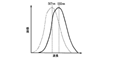
- Embodiment is shown, (a) is a perspective view of an example of use, (b) is principal part sectional drawing. It is a figure which shows the characteristic of visibility. It is principal part sectional drawing which shows the other structural example in embodiment.
- a road lamp is exemplified as the lighting device.
- the technical idea of the present invention can be applied to a lighting device for other purposes as long as it is used in an operation where it is necessary to visually check the front and the surroundings.
- the technique of the present invention can be applied.
- the visual sensitivity characteristics of the human eye correspond to those of photopic vision in the central part of the visual field due to the function of the cone, and in the peripheral part of the visual field the visual sensitivity of scotopic vision by the function of the rod. Become a characteristic. Accordingly, the visibility at the center of the field of view is maximum when the wavelength is around 555 nm as shown by the solid line in FIG. 2, and the visibility at the periphery of the field of view is as shown by the broken line in FIG. In addition, the wavelength becomes maximum at around 507 nm. From the characteristics of the visibility, it can be said that the visibility in the peripheral part of the visual field is enhanced if the light color in the peripheral part of the visual field is different from the light color in the central part in the visual field when the illumination device performs illumination.
- illumination in the main illumination space which is a spatial region corresponding to the central portion of the visual field
- illumination in the sub illumination space which is a spatial region corresponding to the peripheral portion in the visual field.
- Sub-illumination unit employs a technique for making spectral distribution characteristics different.
- the spectral distribution of the light emitted from the illuminating device is represented by f ( ⁇ )
- the photosensitivity characteristic of photopic vision is g ( ⁇ )
- the photosensitivity characteristic h ( ⁇ ) of scotopic vision is the visible light region.
- ⁇ f ( ⁇ ) ⁇ g ( ⁇ ) d ⁇ and ⁇ f ( ⁇ ) ⁇ h ( ⁇ ) d ⁇ are obtained in the range of all wavelengths.
- the former value is referred to as photopic brightness Lp
- the latter value is referred to as scotopic brightness Ls.
- the road has a roadway 1 and a sidewalk 2. Further, it is assumed that a post 3 is erected on the side of the sidewalk 2 on the side of the roadway 1, and a lamp 4 that illuminates the roadway 1 and the sidewalk 2 is provided at the upper end of the post 3. Therefore, immediately below the lamp 4 is near the boundary between the roadway 1 and the sidewalk 2.
- the lamp 4 includes a light emitting diode (hereinafter abbreviated as LED) 11 serving as a light source, an upper cover 12 having an opening on the lower surface and housing the LED 11 inside, and an upper cover 12. And a translucent lower cover 13 covering the opening.
- the upper cover 12 is preferably made of metal.
- the upper cover 12 is made of metal, and the LEDs 11 can be radiated through the upper cover 12 by arranging the plurality of LEDs 11 in close contact with the inner peripheral surface of the upper cover 12.
- the inner peripheral surface of the upper cover 12 forms a concave surface that is recessed upward in a cross section (the cross section shown in FIG. 1) orthogonal to the extending direction of the roadway 1 (that is, the direction in which the automobile travels).
- the inner side surface has a first arrangement surface 14 inclined upward from the side of the road toward the center of the road (that is, from the sidewalk 2 toward the roadway 1), and from the side of the road to the center of the road. And a second arrangement surface 15 that is inclined downward.
- the LED 11 when the LED 11 is arranged on the first arrangement surface 14, illumination light is emitted toward the roadway 1, and when the LED 11 is arranged on the second arrangement surface 15, the illumination light is emitted in a direction away from the roadway 1. .
- the inner surface of the lamp 4 is a concave surface that is recessed upward, if the LED 11 is disposed in the vicinity of the boundary between the first arrangement surface 14 and the second arrangement surface 15, it is possible to illuminate almost directly below the lamp 4. become.
- the visual sensitivity is different between the central part and the peripheral part in the visual field, so the illumination light that illuminates the spatial region corresponding to the central part in the visual field and the peripheral part of the visual field It is desirable that the spectral distribution is different from the illumination light that illuminates the spatial region. That is, according to the above-described principle, it can be said that it is desirable for the driver of the automobile that the spectral distributions of the illumination light that illuminates the roadway 1 and the illumination light that illuminates the sidewalk 2 are different.
- LEDs 11 of a plurality of types of light emission colors are arranged in the lamp 4 as light sources, and the illumination ranges by the LEDs 11 of the respective light emission colors are different.
- the LED 111 that secures the light color and brightness necessary for the illumination of the roadway 1 is mainly disposed on the first arrangement surface 14, and the LED 112 that secures the light color and brightness necessary for the illumination of the sidewalk 2 is mainly the second. It arranges on the arrangement surface 15. Accordingly, the first illumination surface 14 and the LEDs 111 constitute a main illumination unit, and the second arrangement surface 15 and the LEDs 112 constitute an auxiliary illumination unit.
- the light colors of the LED 111 (main illumination unit) and the LED 112 (sub illumination unit) can be variously combined as long as the conditions described as the principle are satisfied.
- the light emitting color of the LED 111 that mainly illuminates the roadway 1 is a light bulb color
- the LED 112 that illuminates the sidewalk 2 is white.
- the S / P ratio on the sidewalk 2 can be made higher than the S / P ratio on the roadway 1. Therefore, compared with the case where the same light bulb color as that of the roadway 1 is used for lighting the sidewalk 2, the visibility of the vicinity of the sidewalk 2 is increased for the driver. That is, the driver can quickly notice the jumping out of people and animals from the sidewalk 2 to the roadway 1.
- the first arrangement surface 14 and the second arrangement surface 15 are formed substantially symmetrically, and the number of LEDs 111 arranged on the first arrangement surface 14 is larger than the number of LEDs 112 arranged on the second arrangement surface 15. There are many. Thus, when the number of the LEDs 112 may be smaller than that of the LEDs 111, the first arrangement surface 14 and the second arrangement surface 15 may be formed asymmetrically. In any case, if at least one of the shapes of the first arrangement surface 14 and the second arrangement surface 15 and the number of the LEDs 111 and 112 is appropriately adjusted, only the necessary range of the roadway 1 and the sidewalk 2 is illuminated. As a result, light pollution can be suppressed.
- the combination of the light colors of the LEDs 111 arranged on the first arrangement surface 14 and the LEDs 112 arranged on the second arrangement surface 15 is not limited to the above-described combination, and can be appropriately selected based on the S / P ratio.
- the LED 111 that illuminates the roadway 1 may be white
- the LED 112 that illuminates the sidewalk 2 may be green.
- the light color may be selected so that the illumination color of the sidewalk 2 includes more components having a shorter wavelength than the illumination color of the roadway 1 in the spectral distribution.
- the lamp 4 may have a cross section (cross section orthogonal to the extending direction of the roadway 1) formed in a rectangular shape.
- the mounting base 16 is disposed inside the upper cover 12.
- the lower surface of the mounting base 16 is a convex surface that protrudes downward, and a first arrangement surface 14 that inclines upward from the sidewalk 2 toward the roadway 1 and a second arrangement surface that inclines downward from the sidewalk 2 toward the roadway 1. 15.
- Both the first arrangement surface 14 and the second arrangement surface 15 are planar, and the boundary between the first arrangement surface 14 and the second arrangement surface 15 is the lower end of the mounting base 16.
- the LED 111 (main illumination unit) arranged on the first arrangement surface 14 and the LED 112 (sub illumination unit) arranged on the second arrangement surface 15 are respectively used for illumination of the roadway 1 and the sidewalk 2. . Moreover, even if the lower cover 13 is provided with diffuse transmission, the light colors of the main illumination unit and the sub illumination unit can be separated and projected.
- the amount of direct light reaching from the LEDs 111 and 112 directly below the lamp 4 is relatively small.
- the light emitted from the LEDs 111 and 112 spreads directly below the lamp 4 and the reflected light from the inner surface of the upper cover 12 wraps around. Therefore, the light directly below the lamp 4 is also shown in FIG.
- the illuminance can be as high as the configuration.
- the light emitted from the LEDs 111 and 112 can be emitted in a wide range.
- the lower cover 13 formed in a shape along the lower surface of the mounting base 16 may be used instead of the flat lower cover 13 shown in FIG.
- the lamp 4 can be thinned.
- the light distribution directly below the lamp 4 is relatively less, so when the roadway 1 and the sidewalk 2 are separated by implantation or the like, This is effective because it can prevent unnecessary illumination.
- FIG. 3B since there is no reflection by the side wall of the upper cover 12, light can be emitted in a wider range than the configuration shown in FIG.
- the lamp 4 can be attached to an appropriate structure disposed above the road. Moreover, it is also possible to arrange the lamp 4 on a structure such as a building or a soundproof wall formed on the road side, not on the road. However, in these lamps 4, it is necessary to change the design of the 1st arrangement surface 14 and the 2nd arrangement surface 15 with embodiment mentioned above.
- the illumination device of the present invention illuminates the main illumination space and the sub illumination space.
- the lighting device includes a main illumination unit that illuminates the main illumination space and a sub-illumination unit that illuminates the sub-illumination space.
- the main illuminator has spectral distribution characteristics, dark place visual sensitivity, and photopic visual sensitivity.
- the product of the spectral distribution characteristic of the main illumination unit and the dark place visual sensitivity of the main illumination unit is defined as the dark place visual brightness of the main illumination unit.
- the product of the spectral distribution characteristics of the main illumination unit and the photopic sensitivity of the main illumination unit is defined as the photopic brightness of the main illumination unit.
- the ratio of the dark place visual luminance of the main illumination unit and the photopic luminance of the main illumination unit is defined as the S / P ratio of the main illumination unit.
- the auxiliary illumination unit has spectral distribution characteristics, dark place visual sensitivity, and photopic visual sensitivity.
- the product of the spectral distribution characteristics of the sub-illumination unit and the scotopic vision sensitivity of the sub-illumination unit is defined as the scotopic brightness of the sub-illumination unit.
- the product of the spectral distribution characteristic of the sub illumination unit and the photopic sensitivity of the sub illumination unit is defined as the photopic brightness of the sub illumination unit.
- the ratio of the dark place visual luminance of the sub illumination unit and the photopic luminance of the sub illumination unit is defined as the S / P ratio of the sub illumination unit.
- the light colors of the main illumination unit and the sub illumination unit are set so that the S / P ratio of the sub illumination unit is larger than the S / P ratio of the main illumination unit.
- the scotopic vision brightness of the main illumination unit is defined as Ls1
- the scotopic vision brightness Ls1 of the main illumination unit satisfies the following expression.
- Ls1 ⁇ f1 ( ⁇ ) ⁇ h ( ⁇ ) d ⁇ f1 ( ⁇ ) is a spectral distribution h ( ⁇ ) of light radiated from the main illumination unit, and is a characteristic of visual sensitivity in scotopic vision.
- the photopic brightness Lp of the illumination unit preferably satisfies the following formula.
- Lp1 ⁇ f1 ( ⁇ ) ⁇ g ( ⁇ ) d ⁇ f1 ( ⁇ ) is a spectral distribution g ( ⁇ ) of light radiated from the main illumination unit, and is a characteristic of photopic visual sensitivity.
- Ls2 ⁇ f2 ( ⁇ ) ⁇ h ( ⁇ ) d ⁇ f2 ( ⁇ ) is a spectral distribution h ( ⁇ ) of light radiated from the sub-illumination unit, and is a characteristic of visibility in dark sight.
- the photopic brightness Lp2 of the illumination unit preferably satisfies the following formula.
- Lp2 ⁇ f2 ( ⁇ ) ⁇ g ( ⁇ ) d ⁇ f2 ( ⁇ ) is the spectral distribution g ( ⁇ ) of the light radiated from the sub-illumination unit, and the photopic visibility characteristic.
- S1 / P ratio of the main illumination unit is defined as S1 / P1
- S1 / P1 Ls1 / Lp1
- S2 / P2 is defined by the following equation.
- the main illumination space is a space region corresponding to a central portion in the visual field
- the sub illumination space is a space region corresponding to a peripheral portion in the visual field.
- the light color of the main illumination unit is a light bulb color
- the light color of the auxiliary illumination unit is white.
- the color temperature of light emitted from the main illumination unit is 2600K or more and 3150K or less.
- the color temperature of the light emitted from the sub illumination unit is 3900K or more and 4500K or less. That is, the light bulb color corresponds to 2600K or more and 3150K or less.
- White corresponds to 3900K or more and 4500K or less.
- the lighting device preferably includes a lamp.
- the lamp has a first arrangement surface and a second arrangement surface.
- the first arrangement surface is inclined upward in the direction from the sub illumination space to the main illumination space.
- the lamp has a first direction along the direction from the sub illumination space to the main illumination space.
- the first arrangement surface is inclined upward in the first direction.
- the first arrangement surface goes upward as it goes in the first direction.
- the second arrangement surface is inclined upward in the direction from the main illumination space to the sub illumination space.
- the lamp has a second direction along the direction from the main illumination space to the sub-illumination space.
- the second arrangement surface is inclined upward in the second direction. In other words, the second arrangement surface goes upward as it goes in the second direction.
- the main illumination unit is formed by arranging light sources on the first arrangement surface.
- the main illumination unit is composed of the first arrangement surface and the light sources arranged on the first arrangement surface.
- the sub illumination unit is formed by arranging light sources on the second arrangement surface.
- the sub-illumination unit is configured by the second arrangement surface and the light sources arranged on the second arrangement surface.
- first arrangement surface and the second arrangement surface are arranged along a direction from the sub illumination space to the main illumination space.
- the first arrangement surface and the second arrangement surface are directed downward.
- the first arrangement surface is located on the first direction side with respect to the second arrangement surface. In other words, the first arrangement surface is closer to the main illumination space than the second arrangement surface.
- the first arrangement surface is located on the second direction side with respect to the second arrangement surface.
- the second arrangement surface is closer to the main illumination space than the first arrangement surface.
- the first arrangement surface is directed to the main illumination space. Therefore, the main illumination unit illuminates the main illumination space.
- the second arrangement surface is directed to the sub illumination space. Therefore, the sub illumination unit illuminates the sub illumination space. Therefore, visibility can be improved.
Landscapes
- Engineering & Computer Science (AREA)
- General Engineering & Computer Science (AREA)
- Non-Portable Lighting Devices Or Systems Thereof (AREA)
Abstract
Description
Ls1=∫f1(λ)・h(λ)dλ
f1(λ)は、主照明部から放射される光の分光分布
h(λ)は、暗所視の視感度の特性
また、前記主照明部の明所視輝度をLp1として定義したとき、主照明部の明所視輝度Lpは、以下の式を満たすことが好ましい。
Lp1=∫f1(λ)・g(λ)dλ
f1(λ)は、主照明部から放射される光の分光分布
g(λ)は、明所視の視感度の特性
また、前記副照明部の暗所視輝度をLs2として定義したとき、副照明部の暗所視輝度Ls2は、以下の式を満たすことが好ましい。
Ls2=∫f2(λ)・h(λ)dλ
f2(λ)は、副照明部から放射される光の分光分布
h(λ)は、暗所視の視感度の特性
また、前記副照明部の明所視輝度をLp2として定義したとき、副照明部の明所視輝度Lp2は、以下の式を満たすことが好ましい。
Lp2=∫f2(λ)・g(λ)dλ
f2(λ)は、副照明部から放射される光の分光分布
g(λ)は、明所視の視感度の特性
そして、主照明部のS/P比をS1/P1として定義したとき、S1/P1は、以下の式で定義される。
S1/P1=Ls1/Lp1
また、副照明部のS/P比をS2/P2として定義したとき、S2/P2は、以下の式で定義される。
S2/P2=Ls2/Lp2
そして、S2/P2がS1/P1よりも大きくなるように、主照明部と副照明部との光色が設定されている。
人の眼の視感度の特性は、視野内の中央部では錐体の機能により明所視の視感度の特性に対応し、視野の周辺部では桿体の機能により暗所視の視感度の特性になる。したがって、視野内の中央部の視感度は、図2に実線で示す曲線のように、波長が555nm付近で最大になり、視野の周辺部の視感度は、図2に破線で示す曲線のように、波長が507nm付近で最大になる。この視感度の特性から、照明装置により照明を行うにあたって、視野の周辺部における光色を視野内の中央部における光色とは異ならせると、視野の周辺部における視認性が高まると言える。
本実施形態では、自動車の運転者から見た路上および路側の視認性を高めた道路灯を例として、上述の原理を用いた実施形態について説明する。自動車の運転者にとっては、視野内の中央部に対応する空間領域は路上であり、視野の周辺部に対応する空間領域は路側である。
Ls1=∫f1(λ)・h(λ)dλ
f1(λ)は、主照明部から放射される光の分光分布
h(λ)は、暗所視の視感度の特性
また、前記主照明部の明所視輝度をLp1として定義したとき、主照明部の明所視輝度Lpは、以下の式を満たすことが好ましい。
Lp1=∫f1(λ)・g(λ)dλ
f1(λ)は、主照明部から放射される光の分光分布
g(λ)は、明所視の視感度の特性
また、前記副照明部の暗所視輝度をLs2として定義したとき、副照明部の暗所視輝度Ls2は、以下の式を満たすことが好ましい。
Ls2=∫f2(λ)・h(λ)dλ
f2(λ)は、副照明部から放射される光の分光分布
h(λ)は、暗所視の視感度の特性
また、前記副照明部の明所視輝度をLp2として定義したとき、副照明部の明所視輝度Lp2は、以下の式を満たすことが好ましい。
Lp2=∫f2(λ)・g(λ)dλ
f2(λ)は、副照明部から放射される光の分光分布
g(λ)は、明所視の視感度の特性
そして、主照明部のS/P比をS1/P1として定義したとき、S1/P1は、以下の式で定義される。
S1/P1=Ls1/Lp1
また、副照明部のS/P比をS2/P2として定義したとき、S2/P2は、以下の式で定義される。
S2/P2=Ls2/Lp2
そして、前記副照明部のS/P比であるS2/P2が、前記主照明部のS/P比であるS1/P1よりも大きくなるように、前記主照明部と前記副照明部との光色が設定されている。
2 歩道(副照明空間)
4 灯具
11 発光ダイオード
111 発光ダイオード(主照明部)
112 発光ダイオード(副照明部)
14 第1配置面(主照明部)
15 第2配置面(副照明部)
Claims (11)
- 主照明空間と副照明空間とを照明する照明装置であって、主照明空間を照明する主照明部と、副照明空間を照明する副照明部とを有し、前記主照明部と前記副照明部とについて、それぞれの分光分布特性と暗所視感度との積により求められる暗所視輝度と、それぞれの分光分布特性と明所視感度との積により求められる明所視輝度との比をS/P比とし、前記副照明部のS/P比を前記主照明部のS/P比よりも大きくなるように、前記主照明部と前記副照明部との光色が設定されていることを特徴とする照明装置。
- 前記主照明空間は、視野内の中央部に対応した空間領域であり、
前記副照明空間は、視野内の周辺部に対応した空間領域であることを特徴とする請求項1に記載の照明装置。
- 前記主照明部と前記副照明部とは、発光ダイオードを光源に用いていることを特徴とする請求項1または2に記載の照明装置。
- 照明対象となる空間領域の上方に配置される灯具を備え、前記灯具は、副照明空間から主照明空間に向かう向きにおいて上り傾斜する第1配置面と、主照明空間から副照明空間に向かう向きにおいて上り傾斜する第2配置面とを備え、前記主照明部は、前記第1配置面に光源を配列することにより形成され、前記副照明部は、前記第2配置面に光源を配列することにより形成されていることを特徴とする請求項1~3のいずれかに記載の照明装置。
- 前記主照明部の光色を電球色とし、前記副照明部の光色を白色としたことを特徴とする請求項1~4のいずれかに記載の照明装置。
- 前記主照明部の発する光の色温度は、2600K以上3150K以下であり、
前記副照明部の発する光の色温度は、3900K以上4500K以下であることを特徴とする請求項1~4のいずれかに記載の照明装置。
- 前記主照明空間は、車道であり、
前記副照明空間は、車道に沿って延びる歩道であることを特徴とする請求項1に記載の照明装置。
- 前記第1配置面及び前記第2配置面は、副照明空間から主照明空間に向かう向きに沿って並んでいることを特徴とする請求項4に記載の照明装置。
- 前記第1配置面及び前記第2配置面は、下方に向けられていることを特徴とする請求項4に記載の照明装置。
- 前記第1配置面は、前記第2配置面よりも、前記第1の方向の側に位置していることを特徴とする請求項4に記載の照明装置。
- 前記第1配置面は、前記第2配置面よりも、前記第2の方向の側に位置していることを特徴とする請求項4に記載の照明装置。
Priority Applications (3)
| Application Number | Priority Date | Filing Date | Title |
|---|---|---|---|
| US13/522,755 US8807787B2 (en) | 2010-02-23 | 2011-02-23 | Illumination device |
| CN2011800107018A CN102869920A (zh) | 2010-02-23 | 2011-02-23 | 照明装置 |
| EP11747383.5A EP2541127B1 (en) | 2010-02-23 | 2011-02-23 | Illumination device |
Applications Claiming Priority (2)
| Application Number | Priority Date | Filing Date | Title |
|---|---|---|---|
| JP2010037914A JP5421817B2 (ja) | 2010-02-23 | 2010-02-23 | 照明装置 |
| JP2010-037914 | 2010-02-23 |
Publications (1)
| Publication Number | Publication Date |
|---|---|
| WO2011105423A1 true WO2011105423A1 (ja) | 2011-09-01 |
Family
ID=44506826
Family Applications (1)
| Application Number | Title | Priority Date | Filing Date |
|---|---|---|---|
| PCT/JP2011/053978 Ceased WO2011105423A1 (ja) | 2010-02-23 | 2011-02-23 | 照明装置 |
Country Status (5)
| Country | Link |
|---|---|
| US (1) | US8807787B2 (ja) |
| EP (1) | EP2541127B1 (ja) |
| JP (1) | JP5421817B2 (ja) |
| CN (1) | CN102869920A (ja) |
| WO (1) | WO2011105423A1 (ja) |
Cited By (3)
| Publication number | Priority date | Publication date | Assignee | Title |
|---|---|---|---|---|
| JP2013149607A (ja) * | 2011-12-19 | 2013-08-01 | Nike Wing:Kk | 高欄照明装置 |
| JP2013152929A (ja) * | 2012-01-06 | 2013-08-08 | Pelican Products Inc | 消防士用照明装置および方法 |
| CN105121941A (zh) * | 2012-11-28 | 2015-12-02 | 皇家飞利浦有限公司 | 具有受控光谱属性和角分布的发光布置 |
Families Citing this family (13)
| Publication number | Priority date | Publication date | Assignee | Title |
|---|---|---|---|---|
| JP5834258B2 (ja) * | 2011-06-22 | 2015-12-16 | パナソニックIpマネジメント株式会社 | 照明装置 |
| KR101894040B1 (ko) * | 2011-12-06 | 2018-10-05 | 서울반도체 주식회사 | 엘이디 조명장치 |
| JP5874045B2 (ja) | 2012-05-11 | 2016-03-01 | パナソニックIpマネジメント株式会社 | 照明装置 |
| ITMI20130798A1 (it) * | 2013-05-15 | 2014-11-16 | Fivep S P A | Dispositivo di illuminazione a led con distribuzione luminosa perfezionata |
| JP5797241B2 (ja) * | 2013-08-19 | 2015-10-21 | 東洋鋼鈑株式会社 | 街路灯 |
| NL2012037C2 (en) | 2013-12-30 | 2015-07-01 | Gemex Consultancy B V | Materials and process for spatial s/p ratio distribution. |
| JP2016062867A (ja) * | 2014-09-22 | 2016-04-25 | スタンレー電気株式会社 | 道路照明灯具 |
| JP6061209B2 (ja) * | 2015-08-07 | 2017-01-18 | スタンレー電気株式会社 | 車両用前照灯 |
| JP6726857B2 (ja) * | 2016-06-03 | 2020-07-22 | パナソニックIpマネジメント株式会社 | 道路灯 |
| JP2018110057A (ja) * | 2016-12-28 | 2018-07-12 | パナソニックIpマネジメント株式会社 | 照明システム、照明方法及びプログラム |
| JP6801549B2 (ja) * | 2017-03-27 | 2020-12-16 | 東芝ライテック株式会社 | テニスコート用照明装置 |
| EP3786519A1 (en) * | 2019-09-02 | 2021-03-03 | ZG Lighting France S.A. | Outdoor street luminaire |
| US20250116382A1 (en) * | 2023-10-06 | 2025-04-10 | Lumileds Llc | Glare free led retrofit lamp, automotive lighting system, and method of assembly |
Citations (2)
| Publication number | Priority date | Publication date | Assignee | Title |
|---|---|---|---|---|
| JP2007242258A (ja) | 2006-03-06 | 2007-09-20 | Iwasaki Electric Co Ltd | 照明装置 |
| WO2009013317A1 (en) * | 2007-07-26 | 2009-01-29 | Lemnis Lighting Patent Holding B.V. | Lighting arrangement |
Family Cites Families (11)
| Publication number | Priority date | Publication date | Assignee | Title |
|---|---|---|---|---|
| TW330233B (en) * | 1997-01-23 | 1998-04-21 | Philips Eloctronics N V | Luminary |
| TW493054B (en) * | 1999-06-25 | 2002-07-01 | Koninkl Philips Electronics Nv | Vehicle headlamp and a vehicle |
| US6676279B1 (en) * | 1999-10-04 | 2004-01-13 | David A. Hubbell | Area lighting device using discrete light sources, such as LEDs |
| CN2575419Y (zh) * | 2002-09-26 | 2003-09-24 | 庄佳璋 | 路灯式照明结构 |
| CN101694274B (zh) * | 2005-06-10 | 2013-02-20 | 莱姆尼斯照明专利控股公司 | 照明装置和固态光源 |
| NL1029231C2 (nl) * | 2005-06-10 | 2007-01-12 | Lemnis Lighting Ip Gmbh | Verlichtingsinrichting en vaste-stof lichtbron. |
| JP4745184B2 (ja) * | 2006-10-03 | 2011-08-10 | スタンレー電気株式会社 | 照明装置 |
| WO2008050850A1 (en) * | 2006-10-25 | 2008-05-02 | Osaka Prefectural Government | Outdoor illuminating device and illuminating method |
| JP4210707B2 (ja) * | 2006-10-25 | 2009-01-21 | 大阪府 | 屋外用照明器具及び照明方法 |
| CN101059211A (zh) * | 2007-05-11 | 2007-10-24 | 江苏江旭电子有限公司 | 高亮度led路灯 |
| JP5170643B2 (ja) * | 2008-01-25 | 2013-03-27 | スタンレー電気株式会社 | 車両用コーナリングランプ |
-
2010
- 2010-02-23 JP JP2010037914A patent/JP5421817B2/ja active Active
-
2011
- 2011-02-23 CN CN2011800107018A patent/CN102869920A/zh active Pending
- 2011-02-23 US US13/522,755 patent/US8807787B2/en not_active Expired - Fee Related
- 2011-02-23 EP EP11747383.5A patent/EP2541127B1/en not_active Not-in-force
- 2011-02-23 WO PCT/JP2011/053978 patent/WO2011105423A1/ja not_active Ceased
Patent Citations (2)
| Publication number | Priority date | Publication date | Assignee | Title |
|---|---|---|---|---|
| JP2007242258A (ja) | 2006-03-06 | 2007-09-20 | Iwasaki Electric Co Ltd | 照明装置 |
| WO2009013317A1 (en) * | 2007-07-26 | 2009-01-29 | Lemnis Lighting Patent Holding B.V. | Lighting arrangement |
Non-Patent Citations (1)
| Title |
|---|
| See also references of EP2541127A4 |
Cited By (5)
| Publication number | Priority date | Publication date | Assignee | Title |
|---|---|---|---|---|
| JP2013149607A (ja) * | 2011-12-19 | 2013-08-01 | Nike Wing:Kk | 高欄照明装置 |
| JP2013152929A (ja) * | 2012-01-06 | 2013-08-08 | Pelican Products Inc | 消防士用照明装置および方法 |
| JP2014239069A (ja) * | 2012-01-06 | 2014-12-18 | ペリカン プロダクツ インコーポレイテッド | 消防士用照明装置および方法 |
| US9074739B2 (en) | 2012-01-06 | 2015-07-07 | Pelican Products, Inc. | Flashlight with multiple light sources |
| CN105121941A (zh) * | 2012-11-28 | 2015-12-02 | 皇家飞利浦有限公司 | 具有受控光谱属性和角分布的发光布置 |
Also Published As
| Publication number | Publication date |
|---|---|
| EP2541127B1 (en) | 2017-08-30 |
| US8807787B2 (en) | 2014-08-19 |
| JP2011175802A (ja) | 2011-09-08 |
| EP2541127A1 (en) | 2013-01-02 |
| CN102869920A (zh) | 2013-01-09 |
| JP5421817B2 (ja) | 2014-02-19 |
| EP2541127A4 (en) | 2015-01-14 |
| US20120287618A1 (en) | 2012-11-15 |
Similar Documents
| Publication | Publication Date | Title |
|---|---|---|
| JP5421817B2 (ja) | 照明装置 | |
| CN101765739B (zh) | 照明装置 | |
| JP4745184B2 (ja) | 照明装置 | |
| US8764223B2 (en) | Lighting device | |
| JP5861110B2 (ja) | 照明器具 | |
| JP6600630B2 (ja) | 放射パターンを選択可能な照明 | |
| JP5512363B2 (ja) | 照明装置 | |
| US10876702B2 (en) | Dual light sources having similar solor temperatures and different spectral characteristics | |
| RU2630684C2 (ru) | Светильник для наружного освещения | |
| US20110176324A1 (en) | Vehicular lamp using planar light-emitting body for sub light source | |
| JP4503960B2 (ja) | 車両用灯具用光源および該車両用灯具用光源を具備する車両用灯具 | |
| JP5834258B2 (ja) | 照明装置 | |
| KR101362186B1 (ko) | 전반사수단이 구비된 엘이디 가로등의 광확산렌즈 | |
| JP3574614B2 (ja) | 発光体及び灯器 | |
| JP5903594B2 (ja) | Led照明器具 | |
| KR200377596Y1 (ko) | 천정등 | |
| JP2012227018A (ja) | 照明器具 | |
| CN216010720U (zh) | 一种飞机、舰船驾驶室用无眩光灯具 | |
| JP7453092B2 (ja) | 照明器具 | |
| JP2014075231A (ja) | 照明装置 | |
| CN104334966B (zh) | 用于降低不适眩光的照明装置和方法 | |
| JP3106557U (ja) | Ledランプ | |
| WO2024155808A1 (en) | Automotive headlighting with improved visibility | |
| TW201348035A (zh) | 車輛燈具之構造 | |
| JP2012185999A (ja) | 照明装置 |
Legal Events
| Date | Code | Title | Description |
|---|---|---|---|
| WWE | Wipo information: entry into national phase |
Ref document number: 201180010701.8 Country of ref document: CN |
|
| 121 | Ep: the epo has been informed by wipo that ep was designated in this application |
Ref document number: 11747383 Country of ref document: EP Kind code of ref document: A1 |
|
| REEP | Request for entry into the european phase |
Ref document number: 2011747383 Country of ref document: EP |
|
| WWE | Wipo information: entry into national phase |
Ref document number: 2011747383 Country of ref document: EP |
|
| WWE | Wipo information: entry into national phase |
Ref document number: 13522755 Country of ref document: US |
|
| NENP | Non-entry into the national phase |
Ref country code: DE |