WO2011105446A1 - 測位方法、測位プログラム、gnss受信装置、および移動端末 - Google Patents
測位方法、測位プログラム、gnss受信装置、および移動端末 Download PDFInfo
- Publication number
- WO2011105446A1 WO2011105446A1 PCT/JP2011/054024 JP2011054024W WO2011105446A1 WO 2011105446 A1 WO2011105446 A1 WO 2011105446A1 JP 2011054024 W JP2011054024 W JP 2011054024W WO 2011105446 A1 WO2011105446 A1 WO 2011105446A1
- Authority
- WO
- WIPO (PCT)
- Prior art keywords
- multipath
- positioning
- error
- pseudorange
- observation
- Prior art date
- Legal status (The legal status is an assumption and is not a legal conclusion. Google has not performed a legal analysis and makes no representation as to the accuracy of the status listed.)
- Ceased
Links
Images



Classifications
-
- G—PHYSICS
- G01—MEASURING; TESTING
- G01S—RADIO DIRECTION-FINDING; RADIO NAVIGATION; DETERMINING DISTANCE OR VELOCITY BY USE OF RADIO WAVES; LOCATING OR PRESENCE-DETECTING BY USE OF THE REFLECTION OR RERADIATION OF RADIO WAVES; ANALOGOUS ARRANGEMENTS USING OTHER WAVES
- G01S19/00—Satellite radio beacon positioning systems; Determining position, velocity or attitude using signals transmitted by such systems
- G01S19/01—Satellite radio beacon positioning systems transmitting time-stamped messages, e.g. GPS [Global Positioning System], GLONASS [Global Orbiting Navigation Satellite System] or GALILEO
- G01S19/13—Receivers
- G01S19/22—Multipath-related issues
-
- G—PHYSICS
- G01—MEASURING; TESTING
- G01S—RADIO DIRECTION-FINDING; RADIO NAVIGATION; DETERMINING DISTANCE OR VELOCITY BY USE OF RADIO WAVES; LOCATING OR PRESENCE-DETECTING BY USE OF THE REFLECTION OR RERADIATION OF RADIO WAVES; ANALOGOUS ARRANGEMENTS USING OTHER WAVES
- G01S19/00—Satellite radio beacon positioning systems; Determining position, velocity or attitude using signals transmitted by such systems
- G01S19/01—Satellite radio beacon positioning systems transmitting time-stamped messages, e.g. GPS [Global Positioning System], GLONASS [Global Orbiting Navigation Satellite System] or GALILEO
- G01S19/13—Receivers
- G01S19/35—Constructional details or hardware or software details of the signal processing chain
- G01S19/37—Hardware or software details of the signal processing chain
-
- G—PHYSICS
- G01—MEASURING; TESTING
- G01S—RADIO DIRECTION-FINDING; RADIO NAVIGATION; DETERMINING DISTANCE OR VELOCITY BY USE OF RADIO WAVES; LOCATING OR PRESENCE-DETECTING BY USE OF THE REFLECTION OR RERADIATION OF RADIO WAVES; ANALOGOUS ARRANGEMENTS USING OTHER WAVES
- G01S19/00—Satellite radio beacon positioning systems; Determining position, velocity or attitude using signals transmitted by such systems
- G01S19/38—Determining a navigation solution using signals transmitted by a satellite radio beacon positioning system
- G01S19/39—Determining a navigation solution using signals transmitted by a satellite radio beacon positioning system the satellite radio beacon positioning system transmitting time-stamped messages, e.g. GPS [Global Positioning System], GLONASS [Global Orbiting Navigation Satellite System] or GALILEO
- G01S19/40—Correcting position, velocity or attitude
-
- G—PHYSICS
- G01—MEASURING; TESTING
- G01S—RADIO DIRECTION-FINDING; RADIO NAVIGATION; DETERMINING DISTANCE OR VELOCITY BY USE OF RADIO WAVES; LOCATING OR PRESENCE-DETECTING BY USE OF THE REFLECTION OR RERADIATION OF RADIO WAVES; ANALOGOUS ARRANGEMENTS USING OTHER WAVES
- G01S19/00—Satellite radio beacon positioning systems; Determining position, velocity or attitude using signals transmitted by such systems
- G01S19/38—Determining a navigation solution using signals transmitted by a satellite radio beacon positioning system
- G01S19/39—Determining a navigation solution using signals transmitted by a satellite radio beacon positioning system the satellite radio beacon positioning system transmitting time-stamped messages, e.g. GPS [Global Positioning System], GLONASS [Global Orbiting Navigation Satellite System] or GALILEO
- G01S19/42—Determining position
-
- G—PHYSICS
- G01—MEASURING; TESTING
- G01S—RADIO DIRECTION-FINDING; RADIO NAVIGATION; DETERMINING DISTANCE OR VELOCITY BY USE OF RADIO WAVES; LOCATING OR PRESENCE-DETECTING BY USE OF THE REFLECTION OR RERADIATION OF RADIO WAVES; ANALOGOUS ARRANGEMENTS USING OTHER WAVES
- G01S19/00—Satellite radio beacon positioning systems; Determining position, velocity or attitude using signals transmitted by such systems
- G01S19/38—Determining a navigation solution using signals transmitted by a satellite radio beacon positioning system
- G01S19/39—Determining a navigation solution using signals transmitted by a satellite radio beacon positioning system the satellite radio beacon positioning system transmitting time-stamped messages, e.g. GPS [Global Positioning System], GLONASS [Global Orbiting Navigation Satellite System] or GALILEO
- G01S19/42—Determining position
- G01S19/428—Determining position using multipath or indirect path propagation signals in position determination
Definitions
- the present invention relates to a positioning method and a positioning program for positioning its own device using positioning signals from GNSS satellites, and particularly to a positioning method and a positioning program for performing positioning calculation using a wake filter having an error covariance matrix. .
- Non-Patent Document 1 a Kalman filter as shown in Non-Patent Document 1 has been conventionally used.
- a covariance matrix is given as a parameter that affects the estimation accuracy of the filter. Specifically, for a wake filter that estimates and calculates pseudoranges and relative velocities at the same time, an error covariance matrix having pseudorange error variance and relative positioning error variance is given.
- Patent Document 1 describes a positioning method in which a multipath is detected from a difference value between an observed pseudorange and an estimated pseudorange, and a received signal (positioning signal) having a large error is not used.
- Patent Document 2 describes a positioning method in which a reception environment is determined from signal strength and an error covariance of a Kalman filter is corrected according to the reception environment.
- the reception environment is judged step by step, a correction value is set for each step, and the initial error covariance is corrected by the correction value.
- the estimation accuracy of the positioning result may be low.
- a vehicle equipped with a positioning device and a positioning antenna travels in an urban area
- a positioning signal reflected on a surrounding high-rise building Multipath
- a positioning signal resulting from such reflection from the surroundings is received and a positioning calculation is performed using the positioning signal, a positioning error increases.
- the positioning error may increase due to the influence of multipath.
- the reception environment is determined from the signal strength, and error variance can be corrected only by the type of the number of stages of the reception environment, and highly accurate positioning calculation corresponding to multipath can be performed. Is not limited.
- an object of the present invention is to realize a positioning method and a positioning device that can perform positioning calculation with high accuracy without being affected by multipath.
- This invention relates to a positioning method for estimating a position or speed from a received signal of a GNSS positioning signal using a wake filter.
- a multipath detection step for detecting a multipath an observation error setting step for setting an error covariance matrix of an observation error, which is a design parameter of a wake filter, based on the presence or absence of multipath detection, and the observation error
- an observation pseudorange calculation step of calculating an observation pseudorange based on the code phase difference of the received signal received at the first time, a position at a second time prior to the first time, and And an estimated pseudo distance calculating step of calculating an estimated pseudo distance based on the calculated position of the GNSS receiver at the first time calculated based on the speed at the second time and the position of the satellite at the first time.
- the multipath detection step detects a multipath based on the observed pseudorange and the estimated pseudorange.
- This method shows a multipath detection method.
- multipath can be detected accurately.
- the error covariance matrix of the observation error corresponding to the multipath can also be set accurately.
- the positioning method of the present invention further includes a threshold setting step for setting a threshold based on the degree of degradation of position accuracy, which is an index of positioning accuracy based on the arrangement of GNSS satellites, and C / No.
- the multipath detection step detects a multipath based on a comparison result between a difference value between the observed pseudorange and the estimated pseudorange and a threshold value.
- This method shows a specific multipath detection method.
- the error variance of the error covariance matrix is set based on the threshold value.
- error variance is set based on C / No when multipath is not detected in the multipath detection step.
- This method shows a specific observation error setting method according to multipath.
- the error variance when multipath is detected is a threshold value
- the error variance when no multipath is detected is an exponential function using C / No obtained experimentally in advance. It is a value calculated from the approximate expression.
- This method shows a specific error variance setting method with and without multipath detection.
- the threshold value set for error variance when multipath is detected is corrected by multiplying by a predetermined correction coefficient.
- This method shows a specific threshold setting method, and by correcting the threshold, it is possible to set a more suitable error variance corresponding to the multipath.
- the correction coefficient for the pseudo distance is different from the correction coefficient for the relative speed.
- This method shows a specific method for setting the correction coefficient. Thereby, the threshold value according to each situation can be set by the pseudo distance and the relative positioning.
- the threshold value is set based on the ⁇ 2 test result in which the observed pseudorange is an observed value and the estimated pseudorange is an expected value.
- This configuration shows a more specific method for setting the threshold.
- an error covariance matrix suitable for each situation can be set without being affected by the presence or absence of multipath. Therefore, the estimation calculation result using the wake filter becomes highly accurate, and the own apparatus position and relative speed can be calculated with high accuracy.
- a positioning method according to an embodiment of the present invention, a positioning program and a positioning device for realizing the positioning method will be described with reference to the drawings. Note that the positioning method, positioning program, and positioning device of the present embodiment can be applied to any positioning system of GNSS.
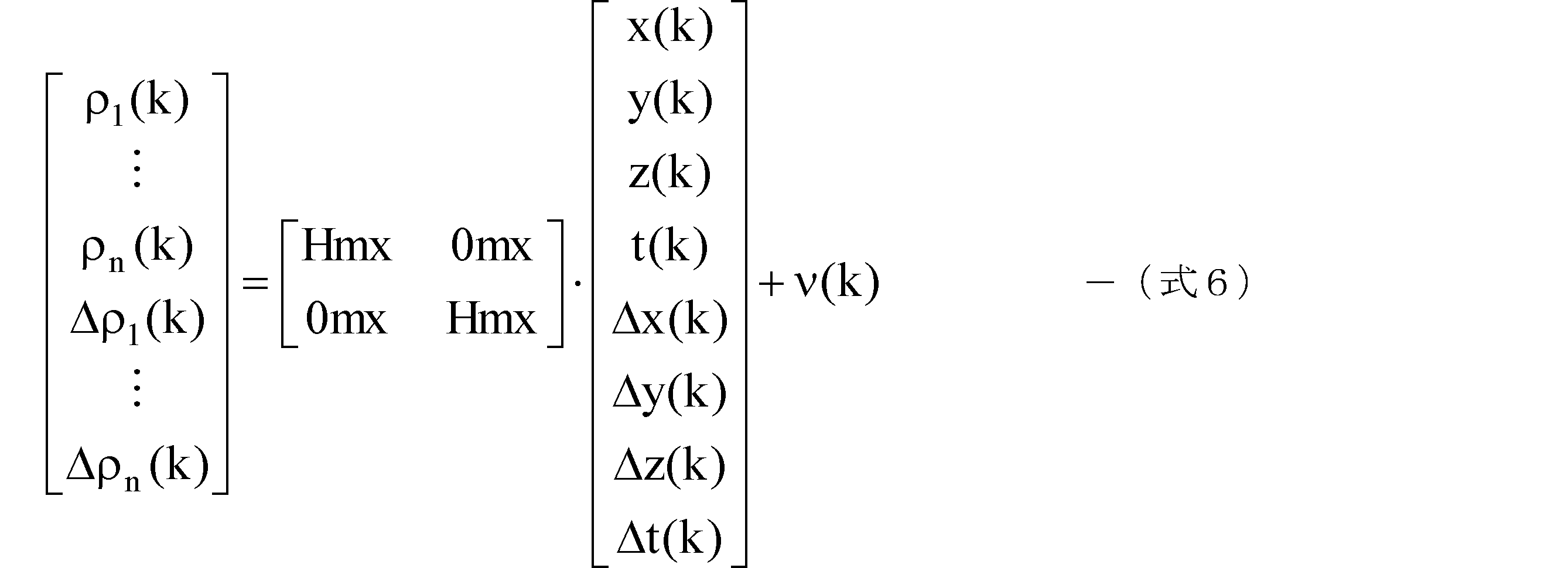
- Equation 1 a wake filter represented by the following equation (Equation 1) is used.
- ⁇ (k) is an observation vector at the calculation timing k
- xx (k) is a state vector at the calculation timing k
- HH is a direction cosine matrix
- ⁇ (k) is an observation error at timing k.
- the observation error ⁇ (k) follows an error covariance matrix RR (k) and a zero-mean multivariate normal (Gaussian) distribution. Therefore, the observation error ⁇ (k) is defined by ⁇ (k) to N (0, RR).
- the observation vector ⁇ (k) is expressed by the following equation.
- ⁇ 1 (k) to ⁇ n (k) are observation pseudoranges between the positioning satellites SV (1) to SV (n) and the own device, respectively, and ⁇ 1 (k) to ⁇ n (k) Is the observed delta range (Doppler shift).
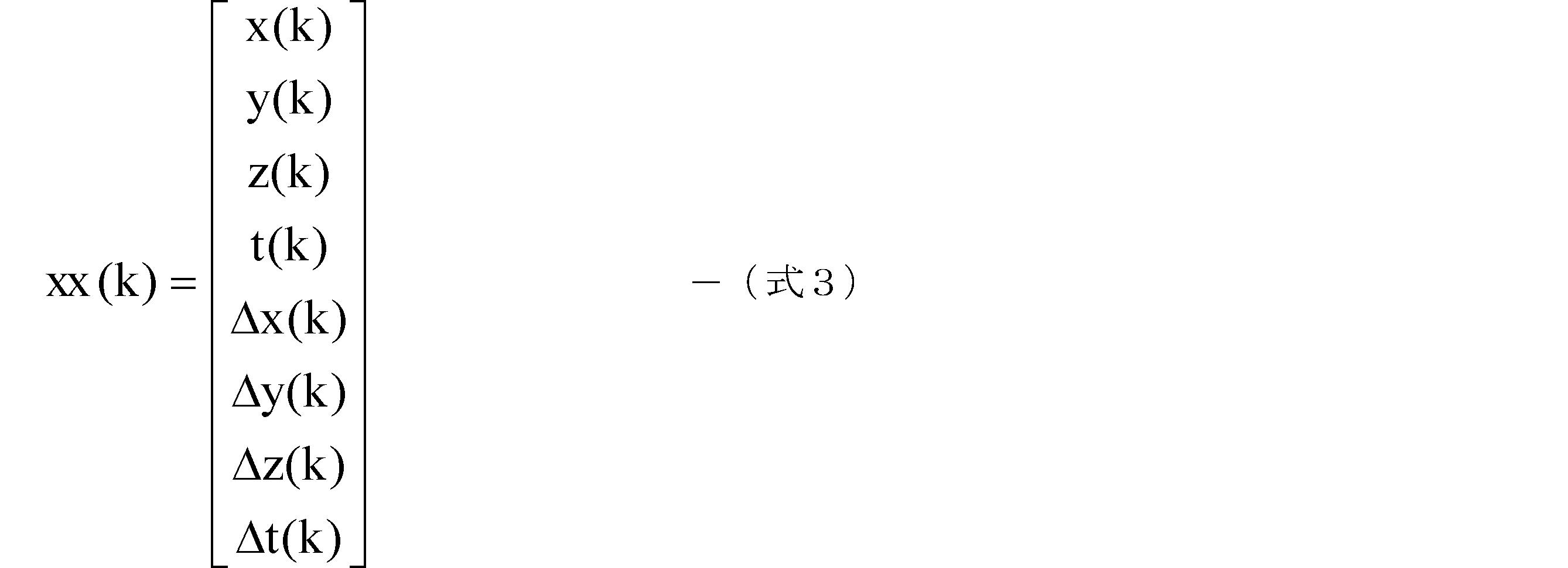
- the state vector xx (k) is expressed by the following equation.
- [x (k), y (k), z (k)] is an estimated position in the orthogonal coordinate system of the own device
- [t (k)] is a receiver clock error of the own device
- [[Delta] x (k), [Delta] y (k), [Delta] z (k)] are relative speeds in the Cartesian coordinate system of the device
- [[Delta] t (k)] is a variation of the receiver clock error of the device. It is.
- HH is the direction cosine matrix expressed by the following equation.
- Hmx is a direction cosine matrix related to pseudorange and relative velocity.
- the direction cosine matrix Hmx is a matrix having (number of satellites) ⁇ 4 elements, and the matrix elements other than the direction cosine matrix Hmx in the direction cosine matrix HH are “0”, and are expressed as a matrix of 0mx in the equation. ing.
- the error covariance matrix RR (k) that determines the observation error ⁇ (k) is expressed by the following equation.
- ⁇ 2 ⁇ 1 (k) to ⁇ 2 ⁇ n (k) are error variances related to pseudoranges for each of the positioning satellites SV (1) to SV (n), and ⁇ 2 ⁇ 1 (k) to ⁇ 2 ⁇ n (k) is an error variance relating to the relative velocity for each of the positioning satellites SV (1) to SV (n).
- Matrix elements other than error variances ⁇ 2 ⁇ 1 (k) to ⁇ 2 ⁇ n (k) and ⁇ 2 ⁇ 1 (k) to ⁇ 2 ⁇ n (k) in the error covariance matrix RR (k) are “0”, In FIG. 4, the matrix is represented as a 0 mx matrix.
- observation error ⁇ (k) is set from the equation (5), and the observation error ⁇ (k) and (Equation 2) to (Equation 4) are substituted into the (Equation 1). A wake filter is obtained.
- the state vector xx (k) is a value calculated by the estimation calculation
- the observation vector ⁇ (k) is an observation value that can be acquired based on the received signal.
- the direction cosine matrix HH is a matrix that performs linear mapping of the estimated position and the observed pseudorange, the estimated relative velocity, and the observed delta range, and is set in advance by a known method.
- Error variances ⁇ 2 ⁇ 1 (k) to ⁇ 2 ⁇ n (k), ⁇ 2 ⁇ 1 (k) to ⁇ 2 ⁇ n (k), which are components of the error covariance matrix RR (k) of the observation error ⁇ (k), are It is set appropriately according to the multipath situation by the following method.
- FIG. 1 shows the time transition between C / No and pseudorange error when a GPS signal from one specific GPS satellite is received over time, showing the multipath dependency between C / No and pseudorange error. It is a figure of the experimental result which shows. This experiment is performed on the premise that the own apparatus position, that is, the true pseudorange is already known.
- the pseudorange error in FIG. 1 is a difference value between the pseudorange and the true pseudorange at each epoch.
- the pseudo distance is calculated from the result of integrating the code correlation result of the received signal according to each count timing by a predetermined time length (for example, 1 second) on the past side.
- C / No in FIG. 1 is calculated from the result of integrating the correlation result based on the two-dimensional correlation spectrum of the received signal according to each epoch for a predetermined time length (for example, 1 second) on the past side.
- the pseudorange error is substantially “0” in the time region of about 80 epochs to 120 epochs and the time region of about 250 epochs to 360 epochs which are hatched portions.
- the time region of about 250 epochs to 360 epochs which are hatched portions.
- C / No is stable in a time region where no multipath occurs (hatching time region), but a time region where a multipath occurs (time other than the hatching time region). In the area), the pseudo-range error and C / No vary.
- each positioning satellite SV1 to SVn (n is an integer and corresponds to the number of observable positioning satellites) has the same error variance setting method, a certain positioning satellite SVm (m is n or less used for convenience of explanation). The method for setting the error variance will be described on the assumption of any integer.
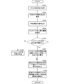
- FIG. 2 is a flowchart of the positioning calculation of the present embodiment, and an error variance setting method, a wake filter error covariance matrix setting method, and a positioning calculation flow will be described along the flowchart. An example in which the own apparatus position is used as an estimated value is shown.
- the observation pseudorange ⁇ m (k) is calculated from the code phase difference of the received signal based on the positioning signal from the positioning satellite SVm (FIG. 2: S101).
- the calculation timing k is a predetermined interval (for example, one second interval)
- the observation pseudo distance ⁇ m (k) is an integration of the code phase error at the epoch included from the immediately preceding timing k-1 to the current timing. Calculated from the value.
- the estimated pseudo distance ⁇ mp (k) for determination is calculated (FIG. 2: S102).
- the calculated position Pos (k-1) and the calculated relative velocity Vel (k-1), which are the estimation results of the previous (k-1), are used, and the current time obtained from the satellite orbit information included in the navigation message.
- the estimated pseudorange ⁇ mp (k) for determination is given by the following equation.
- Tint in the following equation is a time interval between the operation timing (k ⁇ 1) and the operation timing (k), and a symbol surrounded by a double vertical line in the following equation means that a three-dimensional distance is calculated. An arithmetic symbol.
- the determination difference value Delta ⁇ m (k) is calculated from the difference value between the observed pseudo distance ⁇ m (k) and the estimated pseudo distance ⁇ mp (k) for determination (FIG. 2: S103).
- the difference value for determination Delta ⁇ m (k) calculated in this way is equal to or larger than the threshold ⁇ Delta ⁇ indicating the next setting method, it is determined that the multipath is large, and if it is less than the threshold ⁇ Delta ⁇ , the multipath is small. Alternatively, it is a value that can be determined to be almost nonexistent.
- This threshold ⁇ Delta ⁇ is calculated from the following equation (FIG. 2: S104).
- Equation 9 ⁇ 2 POS is the probability of the previously calculated position, and ⁇ 2 Vel is the probability of the relative speed calculated last time.
- the position probability ⁇ 2 POS is calculated by the following equation.
- ⁇ 2 ⁇ CN is the error variance of the pseudorange in the situation where the C / No of the received signal is set to a specific value (for example, 45 [dB-Hz]), and PDOP is the positioning accuracy based on the satellite arrangement. It is an index value.
- PODP corresponds to the degree of positional accuracy degradation of the present invention.
- ⁇ 2 ⁇ CN is the error variance of the delta range in a situation where the C / No of the received signal is set to a specific value (for example, 45 [dB-Hz]).
- the pseudorange error variance ⁇ 2 ⁇ CN can be approximated by the following equation.
- a 0 , a 1 , and a 2 are coefficients that are set as appropriate, and C / No is a specific value as described above.
- a 3 , a 4 , and a 5 are coefficients that are set as appropriate, and C / No is a specific value as described above.
- the threshold ⁇ Delta ⁇ is corrected by a coefficient K set based on the ⁇ 2 test result obtained from the equation (A).
- the ⁇ 2 test performed here is based on the previous observed pseudorange and estimated pseudorange.
- the estimated pseudorange includes the position and relative velocity of the GNSS receiver estimated immediately before, the time interval from the timing of the previous estimation to the timing of ⁇ 2 test, and the positioning satellite position at the timing of ⁇ 2 test. , Calculated from Then, a ⁇ 2 value is calculated from the following (formula A).
- the ⁇ 2 test result is accepted, and if the ⁇ 2 value is larger than the predetermined reference value for determination. The ⁇ 2 test result is rejected.
- correction is performed by multiplying the threshold ⁇ Delta ⁇ by a coefficient K.
- the value of the coefficient K is set smaller than when rejected.
- the threshold value in the situation where the observation value is stable is set smaller than the threshold value in the situation where the observation value is unstable.
- the criteria for multipath can be made stricter in a stable situation than in an unstable situation.
- Such correction of the threshold value ⁇ Delta ⁇ may not be performed, but a more suitable threshold value can be obtained by performing the correction.
- the determination difference value Delta ⁇ m (k) is compared with a K- folded threshold value K ⁇ Delta ⁇ (referred to as “correction threshold value” for convenience of description).
- K ⁇ Delta ⁇ a K- folded threshold value
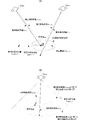
- FIG. 3 is a diagram illustrating the concept of multipath determination.
- FIG. 3A is a conceptual diagram viewed three-dimensionally
- FIG. 3B is a two-dimensional projection for explaining the determination difference value Delta ⁇ m (k).
- FIG. 3 (B) the positioning satellite SVm 2.
- the position that would be obtained by observation based on the observation pseudorange ⁇ m1 (k) is estimated based on the estimated pseudorange ⁇ mpm1 (k) for determination. Close to the position.
- the determination difference value Delta ⁇ m1 (k) between the observation pseudo distance ⁇ m1 (k) and the estimated pseudo distance ⁇ mpm1 (k) for the determination becomes small, and the inside of the hypothesis test adoption region determined by the correction threshold K ⁇ Delta ⁇ . Fit in the area.
- the reception state is stable, and it can be determined that there are few or no multipaths.
- the position that would be obtained based on the observation pseudorange ⁇ m2 (k) is far from the estimated position based on the estimation pseudorange ⁇ mpm2 (k). Yes.
- the determination difference value Delta ⁇ m2 (k) between the observed pseudorange ⁇ m2 (k) and the estimated pseudorange ⁇ mpm2 (k) for determination becomes large, and deviates from the hypothesis test adoption region determined by the correction threshold K ⁇ Delta ⁇ . .
- the situation differs depending on whether the multipath is small (nearly absent) or large, so that the error constituting the error covariance matrix RR (k), which is the design parameter of the wake filter, depends on each situation.
- RR (k) which is the design parameter of the wake filter
- the error of the pseudorange occupies most of the error as described above. Accordingly, assuming that the error is equal to the difference value between the observed value and the estimated value, the difference value for determination is set equal to the value obtained by multiplying the standard deviation of the error by the coefficient K as in the following equation.
- Equation 16 the difference value for determination Delta ⁇ m (k) is expressed by the observation pseudo-range ⁇ m (k) and the estimated pseudo-range ⁇ mp (k) for determination as shown in (Equation 8) described above. Obtained from. PDOP can be calculated from a diagonal element of the direction cosine matrix by a known calculation method. Further, the relative velocity variance ⁇ 2 Vel (k ⁇ 1) is obtained from the previously estimated relative velocity. Therefore, the error variance ⁇ 2 ⁇ (k) of the pseudorange can be calculated by substituting these values into (Expression 16).
- the error variance ⁇ 2 ⁇ (k) of the delta range ⁇ m (k) can also be set by calculating the difference value for determination similarly to the error variance ⁇ 2 ⁇ (k) of the pseudorange described above.
- the difference value Delta ⁇ m for determination in the case of the delta range ⁇ m (k) is expressed by the following equation corresponding to (Equation 8) for the pseudorange ⁇ m (k).
- ⁇ mp (k) is an estimated delta range for determination.
- the estimated delta range for judgment can be calculated from the following equation.
- SvVel (k) is the velocity of the current positioning satellite SV (m) obtained from the satellite orbit information of the navigation message
- Vel (k ⁇ 1) is the own speed obtained from the previous estimation result. The estimated relative speed of the device.
- the determination difference value Delta ⁇ m set in this way, it is determined whether it is less than or equal to the threshold ⁇ Delta ⁇ , as in the case of the pseudo distance described above. If the determination difference value Delta ⁇ m is less than the threshold ⁇ Delta ⁇ , the error variance ⁇ 2 ⁇ m (k) is calculated using the approximate expression of C / No (Equation 13) as in the case of the pseudorange.
- the error variance ⁇ 2 ⁇ m (k) is calculated according to the following concept. First, the variance on both sides of (Equation 17) is taken.
- the error variance ⁇ 2 ⁇ m (k) of the estimation estimated delta range in (Equation 19) can be calculated from the product of the previous error variance ⁇ 2 ⁇ m (k ⁇ 1) and PDOP, and is expressed by the following equation: .
- the left side is the error variance of the delta range
- each element on the right side is a value that can be calculated from the observed value, the previous estimated value, and the direction cosine matrix.
- the error variance ⁇ 2 ⁇ m (k) of the delta range can also be calculated.
- Such error variances ⁇ 2 ⁇ m (k) and ⁇ 2 ⁇ m (k) are calculated for each of the positioning satellites Sv1 to SVn. Then, using each calculated error variance ⁇ 2 ⁇ m (k), ⁇ 2 ⁇ m (k), an error covariance matrix RR (k) is set (FIG. 2: S108).
- the observation error ⁇ (k) is set by the error covariance matrix RR (k) set by the error variance of the pseudorange and the delta range as described above. Further, by substituting the observation error ⁇ (k), the observation pseudorange and the observation delta range constituting the observation vector ⁇ (k) into the wake filter shown in (Equation 6), the positioning calculation is performed, and the estimated position Then, the estimated relative speed is calculated (FIG. 2: S109).
- FIG. 4 is a graph showing the estimation results of the positioning error in the horizontal direction in the process of the present embodiment and the process of setting each error variance of the conventional error covariance matrix to be constant, and the horizontal axis is the time.
- the vertical axis indicates the positioning error. As shown in FIG. 4, by using the processing of the present embodiment, the positioning error can be made smaller than the conventional one regardless of the multipath situation.
- the difference between the setting of the coefficient K for the pseudo distance and the setting of the coefficient K for the delta range is not particularly shown, but these settings may be the same or different.
- the coefficient K ⁇ set for the delta range may be made smaller than the coefficient K ⁇ set for the pseudorange.
- the delta range coefficient K ⁇ may be set to about 10 ⁇ 1 or 10 ⁇ 3 .
- FIG. 5 is a block diagram showing a main configuration of the positioning device 1 of the present embodiment.
- the positioning device 1 of the present embodiment includes a carrier correlation unit 13, a code correlation unit 14, a delta range measurement unit 15, a C / No measurement unit 16, a pseudo distance calculation unit 17, and a positioning calculation unit 18.
- the carrier correlation unit 13 and the code correlation unit 14 are configured by individual loops, but the so-called code correlation result is used for carrier correlation processing, and the carrier correlation result is used for code correlation processing.
- a so-called code-carrier integrated tracking loop may be used.
- the carrier correlation unit 13 and the code correlation unit 14 are connected to the baseband conversion unit 12.
- the baseband converter 12 receives an IF signal obtained by down-converting the GPS signal received by the antenna 10 to an intermediate frequency by the RF processor 11.
- the baseband conversion unit 12 converts the IF signal into a baseband code signal using the carrier frequency signal from the carrier NCO 33 of the carrier correlation unit 13 and outputs it to the code correlation unit 14.
- the carrier correlation unit 13 includes a carrier correlator 31, a loop filter 32, and a carrier NCO 33.
- the carrier correlator 31 multiplies the carrier frequency signal from the carrier NCO 33 by the IF signal of the RF processing unit 11 and outputs a carrier phase difference.
- the output carrier phase difference is fed back to the carrier NCO 33 via the loop filter 32.
- the carrier phase difference is also output to the delta range measurement unit 15.
- the code correlation unit 14 includes a P correlator 41P, an E correlator 41E, an L correlator 41L, an adder 42, a loop filter 43, a code NCO 44, and a shift register 45.
- the code correlation unit 14 is a correlation unit that performs code tracking by performing so-called Early-Late correlation.
- the P correlator 41P multiplies the punctual replica code by the code signal from the baseband conversion unit 12 and outputs punctual phase difference data.
- the E correlator 41E multiplies the early replica code whose code phase is advanced by 1/2 chip with respect to the punctual replica code and the code signal from the baseband conversion unit 12, and outputs Early phase difference data.
- the L correlator 41L multiplies the late replica code whose code phase is delayed by 1 ⁇ 2 chip with respect to the punctual replica code by the code signal from the baseband conversion unit 12 and outputs late phase difference data.
- each phase difference of Early, Punctual, and Late is set to 1/2 chip, but may be set as appropriate according to the situation.
- the adder 42 generates the EL correlation data by subtracting the early phase difference data and the late phase difference data.
- the EL correlation data is fed back to the code NCO 44 through the loop filter 43 and also output to the pseudo distance calculation unit 17.
- the code NCO 44 generates a replica code based on the EL correlation data and outputs it to the shift register 45. Based on the replica code from the code NCO 44, the shift register 45 generates an Early replica code, a punctual replica code, and a late replica code whose code phases are different from each other by 1 ⁇ 2 chip.
- the punctual replica code is output to the P correlator 41P
- the Early replica code is output to the E correlator 41E
- the Late replica code is output to the L correlator 41L.
- the delta range measurement unit 15 calculates the Doppler frequency from the carrier phase difference and integrates a predetermined time length (for example, 1 second) of the Doppler frequency to calculate the observation delta range ⁇ m (k).
- the C / No measurement unit 16 stores the punctual phase difference data from the code correlation unit 14 for a predetermined time length (for example, 1 second), and performs FFT processing on the plurality of punctual phase difference data arranged on the stored time axis.
- the C / No is measured from the correlation result of the two-dimensional correlation spectrum composed of the spectrum on the time axis and the spectrum on the frequency axis. Although a two-dimensional correlation spectrum is used here, other methods may be used.
- the pseudorange calculator 17 calculates the observation pseudorange ⁇ m (k) from a known method based on the EL correlation data from the code correlator 14.
- the positioning calculation unit 18 uses the observation delta range ⁇ m (k) input from the delta range measurement unit 15 and the observation pseudo distance ⁇ m (k) sequentially input from the pseudo distance calculation unit 17 and is demodulated. Using the navigation message, error variances ⁇ 2 ⁇ m (k) and ⁇ 2 ⁇ m (k) are set according to the multipath situation as described above.
- the positioning calculation unit 18 sets the error covariance matrix RR (k) of the wake filter of (Equation 6) using the set error variances ⁇ 2 ⁇ m (k) and ⁇ 2 ⁇ m (k). Then, by substituting the observation pseudorange ⁇ m (k) and the observation delta range ⁇ m (k) into the wake filter of (Equation 6), the device position and relative velocity are estimated and calculated and output.
- the above-described positioning method is realized by a configuration using functional blocks.
- the above-described positioning method is programmed and stored in a memory, and the CPU performs processing and calculation on the program. Then, the positioning calculation process may be executed.
- FIG. 6 is a block diagram illustrating a main configuration of the mobile terminal 100 including the positioning device 1 according to the present embodiment.
- a mobile terminal 100 as shown in FIG. 6 is, for example, a mobile phone, a car navigation device, a PND, a camera, a clock, and the like, and includes an antenna 10, a receiving unit 110, a positioning device 1, and an application processing unit 130.
- the receiver 110 and the positioning device 1 constitute a GNSS receiver 200.
- the antenna 10 is the same as the antenna shown in FIG. 5, and the receiving unit 110 is a functional unit corresponding to the RF processing unit 11 and the baseband converting unit 12 in FIG.
- the positioning device 1 shown in FIG. 6 is the positioning device 1 or the positioning calculation function unit shown in FIG. 5 described above.
- the application processing unit 130 displays the own device position and the own device speed based on the obtained positioning result, and executes processing for use in navigation and the like.
- 1-positioning device 10-antenna, 11-RF processing unit, 12-baseband conversion unit, 13-carrier correlation unit, 31-carrier correlator, 32-loop filter, 33-carrier NCO, 14-code correlation unit, 41P-P correlator, 41E-E correlator, 41L-L correlator, 42-adder, 43-loop filter, 44-code NCO, 45-shift register, 15-delta range measurement unit, 16-C / No Measurement unit, 17-pseudo distance calculation unit, 18-position calculation unit, 100-mobile terminal, 110-reception unit, 120-application processing unit, 200-GNSS reception device
Landscapes
- Engineering & Computer Science (AREA)
- Radar, Positioning & Navigation (AREA)
- Remote Sensing (AREA)
- Computer Networks & Wireless Communication (AREA)
- Physics & Mathematics (AREA)
- General Physics & Mathematics (AREA)
- Signal Processing (AREA)
- Position Fixing By Use Of Radio Waves (AREA)
Abstract
Description














まず、(式17)の両辺の分散を取る。


Claims (17)
- GNSS測位信号の受信信号から航跡フィルタを用いて、位置または速度を算出する測位方法であって、
マルチパスを検出するマルチパス検出工程と、
前記航跡フィルタの設計パラメータである観測誤差の誤差共分散行列を前記マルチパスの検出有無に基づいて設定する観測誤差設定工程と、
該観測誤差設定工程で設定された航跡フィルタを用いて、位置または速度を算出する測位演算工程と、を有することを特徴とする測位方法。 - 請求項1に記載の測位方法であって、
第1時刻に受信した受信信号のコード位相差に基づいて観測擬似距離を算出する観測擬似距離算出工程と、
前記第1時刻よりも過去の第2時刻の位置および該第2時刻の速度に基づき算出した前記第1時刻におけるGNSS受信装置の算出位置と前記第1時刻における衛星の位置とに基づいて推定擬似距離を算出する推定擬似距離算出工程と、をさらに有し、
前記マルチパス検出工程は、前記観測擬似距離と前記推定擬似距離とに基づいてマルチパスを検出する、測位方法。 - 請求項2に記載の測位方法であって、
GNSS衛星の配置に基づく測位精度の指標である位置精度劣化度とC/Noとに基づいて閾値を設定する閾値設定工程をさらに有し、
前記マルチパス検出工程は、前記観測擬似距離と前記推定擬似距離との差分値と前記閾値との比較結果に基づいてマルチパスを検出する、測位方法。 - 請求項3に記載の測位方法であって、
前記観測誤差設定工程は、
前記マルチパス検出工程でマルチパスを検出した場合に、前記閾値に基づいて前記誤差共分散行列の誤差分散を設定し、
前記マルチパス検出工程でマルチパスを検出しない場合に、前記C/Noに基づいて前記誤差分散を設定する、測位方法。 - 請求項4に記載の測位方法であって、
前記マルチパスを検出した場合の前記誤差分散は前記閾値であり、
前記マルチパスを検出しない場合の前記誤差分散は、予め実験的に得られた前記C/Noを用いた指数関数の近似式から算出された値である、測位方法。 - 請求項3乃至請求項5のいずれかに記載の測位方法であって、
前記閾値設定工程は、前記閾値に所定の補正係数を乗算する、測位方法。 - 請求項6に記載の測位方法であって、
擬似距離に対する前記補正係数と、相対速度に対する前記補正係数とが異なっている、測位方法。 - 請求項6または請求項7に記載の測位方法であって、
前記補正係数は、前記観測擬似距離を観測値とし、前記推定擬似距離を期待値とするχ2検定の採否によって異なる、測位方法。 - GNSS測位信号の受信信号から航跡フィルタを用いて、位置または速度を算出するための測位プログラムであって、
マルチパスを検出するマルチパス検出処理と、
前記航跡フィルタの設計パラメータである観測誤差の誤差共分散行列を前記マルチパスの検出有無に基づいて設定する観測誤差設定処理と、
該観測誤差設定工程で設定された航跡フィルタを用いて、位置または速度を算出する測位演算処理と、を有することを特徴とする測位プログラム。 - 請求項9に記載の測位プログラムであって、
第1時刻に受信した受信信号のコード位相差に基づいて観測擬似距離を算出する観測擬似距離算出処理と、
前記第1時刻よりも過去の第2時刻の位置および該第2時刻の速度に基づき算出した前記第1時刻におけるGNSS受信装置の算出位置と前記第1時刻における衛星の位置とに基づいて推定擬似距離を算出する推定擬似距離算出処理と、をさらに有し、
前記マルチパス検出処理は、前記観測擬似距離と前記推定擬似距離とに基づいてマルチパスを検出する、測位プログラム。 - 請求項10に記載の測位プログラムであって、
GNSS衛星の配置に基づく測位精度の指標である位置精度劣化度とC/Noとに基づいて閾値を設定する閾値設定処理をさらに有し、
前記マルチパス検出処理は、前記観測擬似距離と前記推定擬似距離との差分値と前記閾値との比較結果に基づいてマルチパスを検出する、測位プログラム。 - 請求項11に記載の測位プログラムであって、
前記観測誤差設定処理は、
前記マルチパス検出処理でマルチパスを検出した場合に、前記閾値に基づいて前記誤差共分散行列の誤差分散を設定し、
前記マルチパス検出処理でマルチパスを検出しない場合に、前記C/Noに基づいて前記誤差分散を設定する、測位プログラム。 - GNSS測位信号の受信信号に基づいて測位を行うGNSS受信装置であって、
マルチパスを検出するマルチパス検出部と、
前記航跡フィルタの設計パラメータである観測誤差の誤差共分散行列を前記マルチパスの検出有無に基づいて設定する観測誤差設定部と、
該観測誤差設定工程で設定された航跡フィルタを用いて、位置または速度を算出する測位演算部と、を備えることを特徴とするGNSS受信装置。 - 請求項13に記載のGNSS受信装置であって、
第1時刻に受信した受信信号のコード位相差に基づいて観測擬似距離を算出する観測擬似距離算出部と、
前記第1時刻よりも過去の第2時刻の位置および該第2時刻の速度に基づき算出した前記第1時刻におけるGNSS受信装置の算出位置と前記第1時刻における衛星の位置とに基づいて推定擬似距離を算出する推定擬似距離算出部と、をさらに備え、
前記マルチパス検出部は、前記観測擬似距離と前記推定擬似距離とに基づいてマルチパスを検出する、GNSS受信装置。 - 請求項14に記載の測位演算装置であって、
GNSS衛星の配置に基づく測位精度の指標である位置精度劣化度とC/Noとに基づいて閾値を設定する閾値設定部をさらに備え、
前記マルチパス検出部は、前記観測擬似距離と前記推定擬似距離との差分値と前記閾値との比較結果に基づいてマルチパスを検出する、GNSS受信装置。 - 請求項15に記載の測位演算装置であって、
前記観測誤差設定部は、
前記マルチパス検出部でマルチパスを検出した場合に、前記閾値に基づいて前記誤差共分散行列の誤差分散を設定し、
前記マルチパス検出部でマルチパスを検出しない場合に、前記C/Noに基づいて前記誤差分散を設定する、GNSS受信装置。 - 請求項13乃至請求項16のいずれかに記載のGNSS受信装置を備えるとともに、
前記推定演算部の測位演算結果を用いて所定のアプリケーションを実行するアプリケーション処理部を、備える移動端末。
Priority Applications (4)
| Application Number | Priority Date | Filing Date | Title |
|---|---|---|---|
| CN201180010992.0A CN102770782B (zh) | 2010-02-26 | 2011-02-23 | 测位方法、全球导航卫星系统接收装置以及移动终端 |
| US13/581,257 US9121936B2 (en) | 2010-02-26 | 2011-02-23 | Positioning method, GNSS receiving apparatus, and mobile terminal |
| JP2012501831A JP5508515B2 (ja) | 2010-02-26 | 2011-02-23 | 測位方法、測位プログラム、gnss受信装置、および移動端末 |
| EP11747406.4A EP2541278B1 (en) | 2010-02-26 | 2011-02-23 | Location method, location program, gnss receiver apparatus, and mobile terminal |
Applications Claiming Priority (2)
| Application Number | Priority Date | Filing Date | Title |
|---|---|---|---|
| JP2010042854 | 2010-02-26 | ||
| JP2010-042854 | 2010-02-26 |
Publications (1)
| Publication Number | Publication Date |
|---|---|
| WO2011105446A1 true WO2011105446A1 (ja) | 2011-09-01 |
Family
ID=44506848
Family Applications (1)
| Application Number | Title | Priority Date | Filing Date |
|---|---|---|---|
| PCT/JP2011/054024 Ceased WO2011105446A1 (ja) | 2010-02-26 | 2011-02-23 | 測位方法、測位プログラム、gnss受信装置、および移動端末 |
Country Status (5)
| Country | Link |
|---|---|
| US (1) | US9121936B2 (ja) |
| EP (1) | EP2541278B1 (ja) |
| JP (1) | JP5508515B2 (ja) |
| CN (1) | CN102770782B (ja) |
| WO (1) | WO2011105446A1 (ja) |
Cited By (5)
| Publication number | Priority date | Publication date | Assignee | Title |
|---|---|---|---|---|
| JP2014153084A (ja) * | 2013-02-05 | 2014-08-25 | Railway Technical Research Institute | 車両位置計測方法、および車両位置計測システム |
| CN104102822A (zh) * | 2014-07-01 | 2014-10-15 | 同济大学 | 一种多频gnss观测值随机特性建模方法 |
| CN107367744A (zh) * | 2017-08-22 | 2017-11-21 | 温州大学 | 基于自适应测量噪声方差估计的星载gps定轨方法 |
| JP2019095278A (ja) * | 2017-11-22 | 2019-06-20 | 古野電気株式会社 | 解析データ処理装置、解析データ処理方法、および、解析データ処理プログラム |
| CN114355421A (zh) * | 2021-12-22 | 2022-04-15 | 杭州电子科技大学 | 一种基于北斗卫星l4和cmc组合观测值洪水探测方法 |
Families Citing this family (7)
| Publication number | Priority date | Publication date | Assignee | Title |
|---|---|---|---|---|
| US9552648B1 (en) * | 2012-01-23 | 2017-01-24 | Hrl Laboratories, Llc | Object tracking with integrated motion-based object detection (MogS) and enhanced kalman-type filtering |
| CN106488548B (zh) * | 2016-10-25 | 2019-09-17 | 北京邮电大学 | 一种室内多径误差的确定方法及装置 |
| JP6870507B2 (ja) * | 2017-07-07 | 2021-05-12 | 株式会社デンソー | 測位装置 |
| KR102292187B1 (ko) * | 2018-12-14 | 2021-08-24 | 주식회사 피피솔 | Gnss 수신기의 데이터 신호 처리 방법, 기록매체 및 gnss 수신기 시스템, |
| US11513234B2 (en) * | 2019-09-13 | 2022-11-29 | Apple Inc. | Estimating device position in multipath environments |
| CN114384569B (zh) * | 2022-01-12 | 2025-04-18 | 腾讯科技(深圳)有限公司 | 终端定位方法、装置、设备以及介质 |
| CN119644363A (zh) * | 2024-12-12 | 2025-03-18 | 北京航空航天大学合肥创新研究院 | 一种适用于复杂环境下的接收机自主完好性监测方法 |
Citations (7)
| Publication number | Priority date | Publication date | Assignee | Title |
|---|---|---|---|---|
| JPH0868849A (ja) * | 1994-08-31 | 1996-03-12 | Tokimec Inc | 船舶の航法装置 |
| JP2000055679A (ja) * | 1998-08-03 | 2000-02-25 | Alpine Electronics Inc | ナビゲーション装置 |
| JP2003057327A (ja) | 2001-08-09 | 2003-02-26 | Matsushita Electric Ind Co Ltd | 航法衛星信号受信機 |
| JP2006322846A (ja) * | 2005-05-19 | 2006-11-30 | Mitsubishi Electric Corp | Gps受信機 |
| JP2009092541A (ja) | 2007-10-10 | 2009-04-30 | Seiko Epson Corp | 測位方法、プログラム、測位装置及び電子機器 |
| US20090128407A1 (en) * | 2007-11-20 | 2009-05-21 | Sirf Technology, Inc. | Systems and Methods for Detecting GPS Measurement Errors |
| JP2009139281A (ja) * | 2007-12-07 | 2009-06-25 | Xanavi Informatics Corp | 測位方法 |
Family Cites Families (6)
| Publication number | Priority date | Publication date | Assignee | Title |
|---|---|---|---|---|
| US6445692B1 (en) * | 1998-05-20 | 2002-09-03 | The Trustees Of The Stevens Institute Of Technology | Blind adaptive algorithms for optimal minimum variance CDMA receivers |
| US6868276B2 (en) * | 2003-06-17 | 2005-03-15 | Nokia Corporation | Method and apparatus for estimating carrier frequency offset and fading rate using autoregressive channel modeling |
| US8600660B2 (en) * | 2006-09-29 | 2013-12-03 | Honeywell International Inc. | Multipath modeling for deep integration |
| US7551133B2 (en) * | 2007-04-05 | 2009-06-23 | Sirf Technology, Inc. | GPS navigation using interacting multiple model (IMM) estimator and probabilistic data association filter (PDAF) |
| DE102007044671B4 (de) * | 2007-09-18 | 2013-02-21 | Deutsches Zentrum für Luft- und Raumfahrt e.V. | Verfahren zur Schätzung von Parametern eines in einer dynamischen Mehrwegeumgebung empfangenen GNSS-Navigationssignals |
| EP2260320B1 (en) * | 2008-03-20 | 2016-01-13 | Telespazio S.p.A. | Position estimation enhancement for a global navigation satellite system receiver |
-
2011
- 2011-02-23 US US13/581,257 patent/US9121936B2/en active Active
- 2011-02-23 CN CN201180010992.0A patent/CN102770782B/zh active Active
- 2011-02-23 JP JP2012501831A patent/JP5508515B2/ja active Active
- 2011-02-23 WO PCT/JP2011/054024 patent/WO2011105446A1/ja not_active Ceased
- 2011-02-23 EP EP11747406.4A patent/EP2541278B1/en active Active
Patent Citations (7)
| Publication number | Priority date | Publication date | Assignee | Title |
|---|---|---|---|---|
| JPH0868849A (ja) * | 1994-08-31 | 1996-03-12 | Tokimec Inc | 船舶の航法装置 |
| JP2000055679A (ja) * | 1998-08-03 | 2000-02-25 | Alpine Electronics Inc | ナビゲーション装置 |
| JP2003057327A (ja) | 2001-08-09 | 2003-02-26 | Matsushita Electric Ind Co Ltd | 航法衛星信号受信機 |
| JP2006322846A (ja) * | 2005-05-19 | 2006-11-30 | Mitsubishi Electric Corp | Gps受信機 |
| JP2009092541A (ja) | 2007-10-10 | 2009-04-30 | Seiko Epson Corp | 測位方法、プログラム、測位装置及び電子機器 |
| US20090128407A1 (en) * | 2007-11-20 | 2009-05-21 | Sirf Technology, Inc. | Systems and Methods for Detecting GPS Measurement Errors |
| JP2009139281A (ja) * | 2007-12-07 | 2009-06-25 | Xanavi Informatics Corp | 測位方法 |
Non-Patent Citations (2)
| Title |
|---|
| GREG WELCH; GARY BISHOP: "An Introduction to the Kalman Filter", 24 July 2006, DEPARTMENT OF COMPUTER SCIENCE, UNIVERSITY OF NORTH CAROLINA AT CHAPEL HILL |
| See also references of EP2541278A4 * |
Cited By (10)
| Publication number | Priority date | Publication date | Assignee | Title |
|---|---|---|---|---|
| JP2014153084A (ja) * | 2013-02-05 | 2014-08-25 | Railway Technical Research Institute | 車両位置計測方法、および車両位置計測システム |
| CN104102822A (zh) * | 2014-07-01 | 2014-10-15 | 同济大学 | 一种多频gnss观测值随机特性建模方法 |
| CN107367744A (zh) * | 2017-08-22 | 2017-11-21 | 温州大学 | 基于自适应测量噪声方差估计的星载gps定轨方法 |
| CN107367744B (zh) * | 2017-08-22 | 2018-05-01 | 温州大学 | 基于自适应测量噪声方差估计的星载gps定轨方法 |
| JP2019095278A (ja) * | 2017-11-22 | 2019-06-20 | 古野電気株式会社 | 解析データ処理装置、解析データ処理方法、および、解析データ処理プログラム |
| JP7180972B2 (ja) | 2017-11-22 | 2022-11-30 | 古野電気株式会社 | 解析データ処理装置、解析データ処理方法、および、解析データ処理プログラム |
| JP2023015308A (ja) * | 2017-11-22 | 2023-01-31 | 古野電気株式会社 | 解析データ処理装置、解析データ処理方法、および、解析データ処理プログラム |
| JP7467572B2 (ja) | 2017-11-22 | 2024-04-15 | 古野電気株式会社 | 解析データ処理装置、解析データ処理方法、および、解析データ処理プログラム |
| CN114355421A (zh) * | 2021-12-22 | 2022-04-15 | 杭州电子科技大学 | 一种基于北斗卫星l4和cmc组合观测值洪水探测方法 |
| CN114355421B (zh) * | 2021-12-22 | 2023-08-18 | 杭州电子科技大学 | 一种基于北斗卫星l4和cmc组合观测值洪水探测方法 |
Also Published As
| Publication number | Publication date |
|---|---|
| CN102770782B (zh) | 2014-11-19 |
| JPWO2011105446A1 (ja) | 2013-06-20 |
| CN102770782A (zh) | 2012-11-07 |
| US9121936B2 (en) | 2015-09-01 |
| EP2541278A4 (en) | 2015-11-04 |
| JP5508515B2 (ja) | 2014-06-04 |
| EP2541278B1 (en) | 2017-01-18 |
| EP2541278A1 (en) | 2013-01-02 |
| US20120319894A1 (en) | 2012-12-20 |
Similar Documents
| Publication | Publication Date | Title |
|---|---|---|
| JP5508515B2 (ja) | 測位方法、測位プログラム、gnss受信装置、および移動端末 | |
| JP5270184B2 (ja) | 衛星航法/推測航法統合測位装置 | |
| JP4781313B2 (ja) | マルチパス検出装置、測位装置、姿勢方位標定装置、マルチパス検出方法およびマルチパス検出プログラム | |
| CN102782522A (zh) | 伪距推定方法、伪距推定程序、全球导航卫星系统接收装置及移动终端 | |
| US20120319898A1 (en) | Method of detecting multipath, gnss receiving apparatus , and mobile terminal | |
| JP2018136298A (ja) | 搬送波伝播距離のアンビギュイティ推定用分散カルマン・フィルタ・アーキテクチャ | |
| US9253751B2 (en) | Method of calculating movement speed and device for calculating movement speed | |
| CN104880717B (zh) | 一种卫星测量值多路径误差检测装置及其算法 | |
| JP2009139281A (ja) | 測位方法 | |
| JP7329814B2 (ja) | 測位装置、測位方法、測位プログラム、測位プログラム記憶媒体、アプリケーション装置、および、測位システム | |
| JP5526492B2 (ja) | 擬似距離算出方法、測位方法、プログラム及び測位装置 | |
| JP5636552B2 (ja) | 移動受信機による、衛星からの拡散スペクトル信号の取得を最適化する方法 | |
| EP2656097B1 (en) | Method and apparatus for estimating satellite positioning reliability | |
| US11047992B2 (en) | Positioning method and positioning terminal | |
| JP2011179894A (ja) | 測位方法、測位プログラム、gnss受信装置および移動端末 | |
| JP2014238349A (ja) | 測位装置、情報機器端末、測位システム、測位方法、および測位プログラム | |
| JP2013253814A (ja) | 測位方法、測位プログラム、測位装置、および情報機器端末 | |
| KR101854819B1 (ko) | Gps(global positioning system) 수신기의 필터링 | |
| CN107132562A (zh) | 一种实现卡尔曼滤波定位的方法和装置 | |
| JP5903906B2 (ja) | 測位衛星信号受信機、測位衛星信号受信機の処理方法、および、プログラム | |
| JP2009103509A (ja) | Gnss受信装置及び測位方法 | |
| JP2004045126A (ja) | 衛星信号受信機 | |
| WO2017022391A1 (ja) | マルチパス検出装置、マルチパス検出方法、マルチパス検出プログラム、測位装置、測位方法、および測位プログラム | |
| JP2003279635A (ja) | 移動体位置計測システム | |
| JP2001083227A (ja) | Gps受信機 |
Legal Events
| Date | Code | Title | Description |
|---|---|---|---|
| WWE | Wipo information: entry into national phase |
Ref document number: 201180010992.0 Country of ref document: CN |
|
| 121 | Ep: the epo has been informed by wipo that ep was designated in this application |
Ref document number: 11747406 Country of ref document: EP Kind code of ref document: A1 |
|
| WWE | Wipo information: entry into national phase |
Ref document number: 2012501831 Country of ref document: JP |
|
| WWE | Wipo information: entry into national phase |
Ref document number: 13581257 Country of ref document: US |
|
| NENP | Non-entry into the national phase |
Ref country code: DE |
|
| REEP | Request for entry into the european phase |
Ref document number: 2011747406 Country of ref document: EP |
|
| WWE | Wipo information: entry into national phase |
Ref document number: 2011747406 Country of ref document: EP |