WO2011105553A1 - 携帯無線端末、無線端末装置および無線通信システム - Google Patents
携帯無線端末、無線端末装置および無線通信システム Download PDFInfo
- Publication number
- WO2011105553A1 WO2011105553A1 PCT/JP2011/054308 JP2011054308W WO2011105553A1 WO 2011105553 A1 WO2011105553 A1 WO 2011105553A1 JP 2011054308 W JP2011054308 W JP 2011054308W WO 2011105553 A1 WO2011105553 A1 WO 2011105553A1
- Authority
- WO
- WIPO (PCT)
- Prior art keywords
- wireless
- wireless terminal
- communication
- terminal
- unit
- Prior art date
- Legal status (The legal status is an assumption and is not a legal conclusion. Google has not performed a legal analysis and makes no representation as to the accuracy of the status listed.)
- Ceased
Links
Images

Classifications
-
- H—ELECTRICITY
- H02—GENERATION; CONVERSION OR DISTRIBUTION OF ELECTRIC POWER
- H02J—ELECTRIC POWER NETWORKS; CIRCUIT ARRANGEMENTS OR SYSTEMS FOR SUPPLYING OR DISTRIBUTING ELECTRIC POWER; SYSTEMS FOR STORING ELECTRIC ENERGY
- H02J50/00—Circuit arrangements or systems for wireless supply or distribution of electric power
- H02J50/005—Mechanical details of housing or structure aiming to accommodate the power transfer means, e.g. mechanical integration of coils, antennas or transducers into emitting or receiving devices
-
- H—ELECTRICITY
- H02—GENERATION; CONVERSION OR DISTRIBUTION OF ELECTRIC POWER
- H02J—ELECTRIC POWER NETWORKS; CIRCUIT ARRANGEMENTS OR SYSTEMS FOR SUPPLYING OR DISTRIBUTING ELECTRIC POWER; SYSTEMS FOR STORING ELECTRIC ENERGY
- H02J50/00—Circuit arrangements or systems for wireless supply or distribution of electric power
- H02J50/10—Circuit arrangements or systems for wireless supply or distribution of electric power using inductive coupling
-
- H—ELECTRICITY
- H02—GENERATION; CONVERSION OR DISTRIBUTION OF ELECTRIC POWER
- H02J—ELECTRIC POWER NETWORKS; CIRCUIT ARRANGEMENTS OR SYSTEMS FOR SUPPLYING OR DISTRIBUTING ELECTRIC POWER; SYSTEMS FOR STORING ELECTRIC ENERGY
- H02J50/00—Circuit arrangements or systems for wireless supply or distribution of electric power
- H02J50/40—Circuit arrangements or systems for wireless supply or distribution of electric power using two or more transmitting or receiving devices
-
- H—ELECTRICITY
- H02—GENERATION; CONVERSION OR DISTRIBUTION OF ELECTRIC POWER
- H02J—ELECTRIC POWER NETWORKS; CIRCUIT ARRANGEMENTS OR SYSTEMS FOR SUPPLYING OR DISTRIBUTING ELECTRIC POWER; SYSTEMS FOR STORING ELECTRIC ENERGY
- H02J50/00—Circuit arrangements or systems for wireless supply or distribution of electric power
- H02J50/80—Circuit arrangements or systems for wireless supply or distribution of electric power involving the exchange of data, concerning supply or distribution of electric power, between transmitting devices and receiving devices
-
- H—ELECTRICITY
- H02—GENERATION; CONVERSION OR DISTRIBUTION OF ELECTRIC POWER
- H02J—ELECTRIC POWER NETWORKS; CIRCUIT ARRANGEMENTS OR SYSTEMS FOR SUPPLYING OR DISTRIBUTING ELECTRIC POWER; SYSTEMS FOR STORING ELECTRIC ENERGY
- H02J7/00—Circuit arrangements for charging or discharging batteries or for supplying loads from batteries
- H02J7/40—Circuit arrangements for charging or discharging batteries or for supplying loads from batteries characterised by the exchange of charge or discharge related data
- H02J7/42—Circuit arrangements for charging or discharging batteries or for supplying loads from batteries characterised by the exchange of charge or discharge related data with electronic devices having internal batteries, e.g. mobile phones
-
- H—ELECTRICITY
- H02—GENERATION; CONVERSION OR DISTRIBUTION OF ELECTRIC POWER
- H02J—ELECTRIC POWER NETWORKS; CIRCUIT ARRANGEMENTS OR SYSTEMS FOR SUPPLYING OR DISTRIBUTING ELECTRIC POWER; SYSTEMS FOR STORING ELECTRIC ENERGY
- H02J7/00—Circuit arrangements for charging or discharging batteries or for supplying loads from batteries
- H02J7/70—Circuit arrangements for charging or discharging batteries or for supplying loads from batteries characterised by the mechanical construction
- H02J7/731—Circuit arrangements for charging or discharging batteries or for supplying loads from batteries characterised by the mechanical construction specially adapted for holding portable devices containing batteries
Definitions
- the present invention relates to a portable wireless terminal, a wireless terminal device, and a wireless communication system.
- This application claims priority based on Japanese Patent Application No. 2010-40096 filed in Japan on February 25, 2010, the contents of which are incorporated herein by reference.
- wireless communication functions can be implemented in transceivers at low cost.
- multiple pairs of transmitters / receivers are introduced into general households and corporate facilities, and communication settings (such as ID (identification data) and identification information) required for the transmitter / receiver to perform wireless communication are set. Exchange) etc. are also increasing.
- the transmitter / receiver it is also necessary for the transmitter / receiver to have an application for frequently changing the other party to perform wireless communication.
- the transceiver when the transceiver is made wireless, the transceiver must be driven using a battery in order to enjoy the advantage of not using a cable.
- a rechargeable secondary battery such as a Ni—Cd (nickel cadmium) battery or a lithium battery is often used.
- a charging method for the secondary battery a charging method using non-contact power transmission that does not require an electrical contact using electromagnetic induction or the like has been established.
- a charging method using contactless power transmission products that are used in wet locations where electrical contacts are not good are popular.
- a technique of superimposing a data transmission signal on a contactless power transmission path is disclosed (for example, see Patent Document 1).
- the non-contact power transmission path transmits data at a frequency lower than a frequency (several hundred MHz or more) used as a carrier frequency for high-speed data transmission. . Therefore, it is difficult to improve the data transmission rate of the non-contact power transmission path, and the non-contact power transmission path is not suitable for the purpose of transmitting large-capacity image data or the like in a short time.
- the present invention has been made to solve the above-described problem, and provides a portable wireless terminal, a wireless terminal device, and a wireless communication system that can easily perform communication settings for wireless communication. Objective.
- the present invention includes a battery unit for storing power, a terminal wireless data communication unit for wirelessly communicating information, a terminal communication setting unit for setting predetermined setting information related to wireless communication by the terminal wireless data communication unit, And a power receiving antenna that receives power for charging the battery unit from an external terminal, and a power receiving antenna that transmits or receives the setting information to or from the external terminal.
- the power receiving antenna transmits or receives information necessary for starting wireless communication by the terminal wireless data communication unit as the setting information.
- the setting information is identification information or encrypted information of the wireless communication.
- the power receiving antenna transmits or receives the setting information during the charging or power receiving.
- the present invention also provides a wireless data communication unit that wirelessly communicates information, a communication setting unit that sets predetermined setting information related to wireless communication by the wireless data communication unit, and power transmission that transmits power to an external terminal without contact It is an antenna, and is a portable terminal device having a power transmission antenna that transmits or receives the setting information to or from the external terminal.
- the power transmission antenna and the wireless data communication unit are arranged in separate housings.
- the present invention is a wireless communication system including a portable wireless terminal and a wireless terminal device
- the portable wireless terminal includes a battery unit for storing power, a terminal wireless data communication unit for wirelessly communicating information, A terminal communication setting unit configured to set predetermined setting information related to wireless communication by the terminal wireless data communication unit; and a power receiving antenna configured to receive electric power for charging the battery unit without contact from the wireless terminal device, A power receiving antenna that transmits or receives information to or from the wireless terminal device, the wireless terminal device wirelessly communicating information, and a predetermined wireless communication by the wireless data communication unit
- a communication setting unit that sets setting information; and a power transmission antenna that transmits power to the portable wireless terminal without contact, and transmits the setting information to and from the portable wireless terminal Is a wireless communication system comprising a transmission antenna for receiving the.
- the terminal communication setting unit includes the wireless terminal device in which the terminal wireless data communication unit performs wireless communication, and the wireless terminal device in which the power receiving antenna transmits or receives the setting information. It is desirable to limit to.
- the communication setting unit limits the portable wireless terminal that the wireless data communication unit performs wireless communication to the portable wireless terminal that the power transmission antenna transmits or receives the setting information. It is desirable to do.
- the reach distance of the wireless communication line between the power transmission antenna and the power receiving antenna is approximately the same as the distance at which power can be transmitted without contact. Is desirable.
- the power receiving antenna that receives the power for charging the battery unit without contact from the external terminal transmits or receives the predetermined setting information related to the wireless communication by the terminal wireless data communication unit. Therefore, it is possible to perform communication settings for performing wireless communication without performing complicated input to the wireless device.
- FIG. 1 is a block diagram illustrating a schematic configuration of a wireless communication system according to a first embodiment of the present invention. It is the schematic which showed the group to which the radio
- FIG. 1 is a block diagram showing a schematic configuration of a wireless communication system in the present embodiment.
- the wireless communication system includes a wireless terminal device 10 and a portable wireless terminal 20.
- the wireless terminal device 10 includes a main body unit 11 and a contactless power transmission unit 102.
- the main body 11 includes a power supply unit 101, a storage unit 103, a communication setting unit 104, and a high-speed wireless communication unit 105 (wireless data communication unit).
- the non-contact power transmission unit 102 includes a coil antenna 1021 (power transmission antenna).
- the portable wireless terminal 20 includes a contactless power receiving unit 201, a battery 202, a terminal communication setting unit 203, a terminal storage unit 204, and a terminal high-speed wireless communication unit 205 (terminal wireless data communication unit).
- the non-contact power receiving unit 201 includes a coil antenna 2011 (power receiving antenna).
- the power source unit 101 is connected to a commercial AC power source and supplies power supplied from the commercial AC power source to each unit included in the wireless terminal device 10.
- the non-contact power transmission unit 102 modulates the power supplied from the power supply unit 101 so that the non-contact power reception unit 201 of the portable wireless terminal 20 can receive power efficiently, and transmits the modulated power via the coil antenna 1021.
- the non-contact power transmission unit 102 communicates with the non-contact power reception unit 201 of the portable wireless terminal 20 via the coil antenna 1021 using the second wireless communication line.
- the second wireless communication line will be described later.
- the storage unit 103 stores information necessary for performing communication using the first wireless communication line.
- the first wireless communication line will be described later.
- the communication setting unit 104 performs communication settings for the first wireless communication line.
- the high-speed wireless communication unit 105 communicates with the terminal high-speed wireless communication unit 205 of the portable wireless terminal 20 using the first wireless communication line.
- the contactless power receiving unit 201 converts the power received from the contactless power transmitting unit 102 via the coil antenna 2011 into direct current and charges the battery 202.
- the contactless power receiving unit 201 communicates with the contactless power transmission unit 102 of the wireless terminal device 10 via the coil antenna 2011 using the second wireless communication line.
- the battery 202 is a secondary battery and supplies power to each unit included in the mobile wireless terminal 20.
- the terminal communication setting unit 203 performs communication settings for the first wireless communication line.
- the terminal storage unit 204 stores information necessary for performing communication using the first wireless communication line.
- the terminal high-speed wireless communication unit 205 communicates with the high-speed wireless communication unit 105 of the wireless terminal device 10 using the first wireless communication line.
- the main body unit 11 and the non-contact power transmission unit 102 are separate casings, but may be integrated.
- the contactless power transmission unit 102 is configured such that when the portable wireless terminal 20 is placed on the contactless power transmission unit 102, the coil antenna 1021 of the contactless power transmission unit 102 and the coil antenna 2011 of the contactless power reception unit 201. Is preferably in the shape of a cradle that is set in a positional relationship preferable for contactless power transmission.
- the wireless terminal device 10 is assumed to have a rich GUI (Graphical User Interface, graphical user interface) like a personal computer.
- the portable wireless terminal 20 is inconvenient for character input or the like like a digital camera. A case where a personal computer and a digital camera communicate with each other is a well-known case.
- the first wireless communication line is a high-speed data communication line represented by a wireless LAN standardized by IEEE802.11a / b / g.
- the high-speed wireless communication unit 105 of the wireless terminal device 10 and the terminal high-speed wireless communication unit 205 of the portable wireless terminal 20 perform communication using the first wireless communication line.
- the first wireless communication line generally has a reach of several meters to several tens of meters, and enables high-speed data exchange within that range.
- the first wireless communication line is not limited to a standardized communication method, and may be an original wireless method.
- the communication setting is a setting for specifying a communication destination and the like, and is a general setting required when performing communication using a wireless LAN or the like.
- the group ID is information that can uniquely identify the group to which the wireless terminal device 10 and the portable wireless terminal 20 belong.
- the second wireless communication line is a wireless communication line using a technique for superimposing a data transmission signal on a contactless power transmission path. Therefore, the coil antenna 2011 of the non-contact power receiving unit 201 can transmit or receive the setting information while receiving power from the coil antenna 1021 of the non-contact power transmitting unit 102 or charging the battery 202.
- the communicable distance (data signal reachable distance) on the second wireless communication line is the same distance as the distance at which power can be transmitted without contact.
- the frequency used as the carrier frequency for data transmission using the second wireless communication line is lower than the frequency (several hundred MHz or more) used as the carrier frequency for high-speed data transmission these days. Therefore, the data transmission rate of the second wireless communication line is low.
- the transmission distance of the second wireless communication line is more convenient as the transmission distance is shorter from the viewpoint of data confidentiality, so it is preferable to determine the transmission distance with a trade-off with usability.
- the contactless power transmission unit 102 of the wireless terminal device 10 and the contactless power receiving unit 201 of the mobile wireless terminal 20 use the first wireless communication line using the second wireless communication line. Information such as a group ID and an encryption key necessary for communication is transmitted / received.
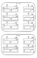
- FIG. 2 is a schematic diagram illustrating a group to which the wireless terminal device 10 and the portable wireless terminal 20 included in the wireless communication system according to the present embodiment belong.
- the wireless communication system includes wireless terminal devices 10a to 10e and portable wireless terminals 20a to 20e.
- the wireless terminal devices 10a to 10c and the portable wireless terminals 20a to 20c belong to the group A
- the wireless terminal devices 10d to 10e and the portable wireless terminals 20d to 20e belong to the group B.
- the wireless terminal device 10 and the portable wireless terminal 20 that belong to the same group are set to communicate with each other because the owners of the group A and the group B are different, but the wireless terminal device that belongs to the group A Assume that it is necessary to make settings so that communication is not possible between 10a-c and portable wireless terminals 20d-e belonging to group B. Further, it is assumed that the wireless terminal devices 10d to 10e belonging to the group B and the portable wireless terminals 20a to 20c belonging to the group A need to be set so as not to communicate with each other.
- the communication setting method for performing communication between the high-speed wireless communication unit 105 of the wireless terminal device 10 and the terminal high-speed wireless communication unit 205 of the portable wireless terminal 20 using the first wireless communication line belongs to the group A.
- the wireless terminal devices 10a to 10c, the portable wireless terminals 20a to 20c, the wireless terminal devices 10d to 10e belonging to the group B, and the portable wireless terminals 20d to 20e have a common group ID and encryption key in each group. If there is no communication, the system is set so that communication cannot be performed.
- This communication setting is performed by the communication setting unit 104 of the wireless terminal device 10 and the terminal communication setting unit 203 of the portable wireless terminal 20.
- the communication setting unit 104 transmits the group ID and the encryption key stored in advance in the storage unit 103 of the wireless terminal device 10 to the portable wireless terminal 20 using the second wireless communication line. It is assumed that the group ID and the encryption key are input to the wireless terminal device 10 by a known method, and the input group ID and encryption key are stored in the storage unit 103.
- a simple method for inputting a group ID and an encryption key to the wireless terminal device 10 is that an operator inputs an arbitrarily determined group ID and encryption key using a keyboard, mouse, or the like provided in the wireless terminal device 10. Is the method.
- the procedure for transmitting the group ID and the encryption key from the wireless terminal device 10 to the portable wireless terminal 20 using the second wireless communication line is as follows.
- the operator brings the contactless power receiving unit 201 of the wireless terminal device 10 close to the contactless power transmission unit 102 of the wireless terminal device 10.
- the communication setting unit 104 transmits the group ID and the encryption key stored in advance in the storage unit 103 to the contactless power receiving unit 201 via the contactless power transmission unit 102.
- the contactless power receiving unit 201 receives the transmitted group ID and encryption key and inputs them to the terminal communication setting unit 203.
- the terminal communication setting unit 203 performs communication settings for the first wireless communication line based on the input group ID and encryption key, and causes the terminal storage unit 204 to store the group ID and encryption key. With this communication setting, the wireless terminal device 10 and the portable wireless terminal 20 that store the same group ID and encryption key can communicate using the first wireless communication line.
- the operator simply brings the contactless power receiving unit 201 of the portable wireless terminal 20 close to the contactless power transmitting unit 102 of the wireless terminal device 10 as in the case of performing charging by normal contactless power transmission.
- the group ID and encryption key can be exchanged between the wireless terminal device 10 and the portable wireless terminal 20. Furthermore, even when the GUI of the mobile radio terminal 20 is not sufficient, the operator can input the group ID and the encryption key to the mobile radio terminal 20 very simply.
- the operator sets the contactless power receiving unit 201 of the portable wireless terminal 20 to Exchange of group ID and encryption key between the wireless terminal device 10 and the portable wireless terminal 20 belonging to the same group only by bringing the wireless terminal device 10 belonging to the same group closer to the contactless power transmission unit 102 Can do. Therefore, the operator can easily set so that only the wireless terminal device 10 and the portable wireless terminal 20 belonging to the same group can communicate with each other.
- the problem regarding the data confidentiality of the group ID and the encryption key can be solved because the communication distance of the second wireless communication line is short. That is, since the communication distance of the second wireless communication line is short, it is easy to prevent a malicious third party from approaching the contactless power transmission unit 102 of the wireless terminal device 10. Accordingly, if the third party is prevented from approaching the non-contact power transmission unit 102, the third party cannot transmit the group ID and the encryption key to the portable wireless terminal 20, and therefore the group ID and the encryption key are not transmitted. Data confidentiality can be protected. Further, if a confirmation screen for transferring the group ID and the encryption key is prepared in the wireless terminal device 10 and an input of a password or the like is requested, the confidentiality can be further enhanced.
- the group ID and the encryption key are exchanged using the second wireless communication line, but the information transmitted and received using the second wireless communication line is limited to this. is not.
- Information for enhancing the confidentiality of data may be transmitted using the second wireless communication line.
- transmission of main information (for example, images, sounds, texts, application files, etc.) transmitted and received using the first wireless communication line is limited within the group. However, this does not deny any communication with other groups, and control communication such as collision avoidance is also performed with devices belonging to other groups.
- the wireless terminal device 10 and the portable wireless terminal 20 perform communication setting of the first wireless communication line by exchanging the group ID and the encryption key using the second wireless communication line. Therefore, the first wireless communication setting can be realized without complicated input of the communication setting information.
- the second wireless communication line is a wireless communication line using a technique for superimposing a data transmission signal on a contactless power transmission line. Therefore, it is possible to perform communication settings for the first wireless communication line without having to install individual antennas for close proximity wireless communication between the wireless terminal device 10 and the portable wireless terminal 20. Therefore, the manufacturing cost can be reduced and the product can be downsized.
- the configuration of the wireless terminal device 10 and the portable wireless terminal 20 in the present embodiment is the same as that of each device in the first embodiment.
- the main information transmission target of the first wireless communication line is limited to one of the plurality of wireless terminal devices 10 and one of the plurality of portable wireless terminals 20. That is, an example that is generally effective in communication called P2P (Peer to Peer) will be described.
- the portable wireless terminal 20 is an image transmission device that includes a CCD (Charge Coupled Device) sensor and transmits a captured moving image (image) to the wireless terminal device 10.
- the wireless terminal device 10 is a device that displays a moving image (image) received from the mobile wireless terminal 20 on a monitor in real time. A case where these devices perform P2P communication will be described as an example. More specifically, the present invention provides a system in which the operator changes the direction and position of the CCD sensor provided in the portable wireless terminal 20 while observing the monitor of the wireless terminal device 10 and freely observes various parts. Is suitable.
- the wireless communication system includes a plurality of wireless terminal devices 10 and portable wireless terminals 20 and the pair of P2P communication between the wireless terminal device 10 and the portable wireless terminal 20 is frequently changed
- this The invention has an effect. For example, it is required to frequently change the pair of P2P communication.
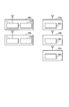
- FIG. 3 is a schematic diagram illustrating the wireless terminal device 10 and the portable wireless terminal 20 included in the wireless communication system according to the present embodiment.
- the wireless communication system includes wireless terminal apparatuses 10a to 10b and portable wireless terminals 20a to 20c.
- the operator sets the portable wireless terminal 20c in the contactless power transmission unit 102 of the fixed wireless terminal 10a.
- the communication setting unit 104 of the wireless terminal device 10a and the terminal communication setting unit 203 of the portable wireless terminal 20c detect that the portable wireless terminal 20c is set in the contactless power transmission unit 102 of the wireless terminal device 10a, the second setting is performed.
- Each individual identification information (UID) is exchanged using a wireless communication line.
- the individual identification information is information that uniquely identifies the wireless terminal device 10 or the portable wireless terminal 20.
- the communication setting unit 104 and the terminal communication setting unit 203 change each other's main information transmission destination device (P2P communication connection destination) to a device uniquely identified by the individual identification information exchanged with each other.
- P2P communication connection destination main information transmission destination
- This operation is a rewriting operation, and the communication setting unit 104 and the terminal communication setting unit 203 erase the individual identification information recorded and held in the storage unit 103 and the terminal storage unit 204. At the same time, the communication setting unit 104 and the terminal communication setting unit 203 record and hold the newly received individual identification information in the storage unit 103 and the terminal storage unit 204.
- the communication setting unit 104 and the terminal communication setting unit 203 are programmed so as to perform such an operation, in a specific example of a system for transferring a moving image (image) in real time, the operator of the wireless terminal device 10a Just by setting the portable wireless terminal 20c in the non-contact power transmission unit 102, the moving image (image) captured by the CCD sensor included in the portable wireless terminal 20c in front of the eye is displayed on the monitor screen provided in the wireless terminal device 10a in front of the eye. be able to.
- the wireless terminal device 10a and the portable wireless terminal 20c can use the wireless terminal device 10c and the portable wireless terminal 20a or b in parallel.
- the communication between the wireless terminal device 10 and the portable wireless terminal 20 is intended to be P2P communication. Therefore, when the communication counterparts of a plurality of mobile radio terminals 20 are one radio terminal apparatus 10, only the mobile radio terminal 20 that is powered on first can communicate with the radio terminal apparatus 10 or the like. Arrangements and controls are required. You may give priority to the portable wireless terminal 20 that is turned on later.
- the following can be considered.
- the best method may be selected according to the situation of the wireless communication system.
- the mobile wireless terminal 20 When an electromotive voltage generated in the contactless power receiving unit 201 of the mobile wireless terminal 20 is detected by contactless power transmission, the mobile wireless terminal 20 is set in the contactless power transmission unit 102 of the wireless terminal device 10. How to detect. In this case, it is necessary to always move the non-contact power transmission unit 102 of the wireless terminal device 10. However, it is possible to achieve power saving by using a process such as lowering the applied power of the contactless power transmission unit 102 or operating the contactless power transmission unit 102 with a time interval. is there.
- a sensor using magnetism such as a magnet and a hall sensor, or a sensor using light detection such as an optical sensor and a light receiving element is provided, and the portable wireless terminal 20 is connected to the wireless terminal device 10 according to the detection result of the sensor.
- a method of detecting that the power transmission unit 102 is set. In this case, it is necessary to install a sensor or element in the contactless power transmission unit 102 or the portable wireless terminal 20.
- the portable wireless terminal 20 A method of detecting that the contact power transmitter 102 is set.
- the communication setting unit 104 of the wireless terminal device 10 and the terminal communication setting unit 203 of the mobile wireless terminal 20 indicate that the mobile wireless terminal 20 is set in the contactless power transmission unit 102 of the wireless terminal device 10. Is detected, the individual identification information is exchanged using the second wireless communication line, and the communication destination of the main information is changed to a device uniquely specified by the exchanged individual identification information. As a result, it is possible to set a pair of P2P communication information transmissions without complicated input. Furthermore, since the second wireless communication line is a wireless communication line using a technique for superimposing a data transmission signal on a contactless power transmission path, it can be realized without the need to install a separate antenna for close proximity wireless communication. Therefore, the manufacturing cost can be reduced and the product can be downsized.
- the setting information (in the first embodiment, the storage unit 103 of the wireless terminal device 10 needs to perform communication using the first wireless communication line).
- An example is shown in which a group ID and an encryption key (individual identification information in the second embodiment) are stored and transmitted from the wireless terminal device 10 to the portable wireless terminal 20 using the second wireless communication line.
- the terminal storage unit 204 of the portable wireless terminal 20 stores setting information necessary for performing communication using the first wireless communication line, and the portable wireless terminal 20 using the second wireless communication line. To the wireless terminal device 10.
- the power receiving antenna that receives the power for charging the battery unit without contact from the external terminal transmits or receives the predetermined setting information related to the wireless communication by the terminal wireless data communication unit. Therefore, it is possible to perform communication settings for performing wireless communication without performing complicated input to the wireless device.
Landscapes
- Engineering & Computer Science (AREA)
- Power Engineering (AREA)
- Computer Networks & Wireless Communication (AREA)
- Telephone Function (AREA)
- Mobile Radio Communication Systems (AREA)
- Transceivers (AREA)
- Near-Field Transmission Systems (AREA)
Abstract
無接点で電力を伝送し充電する機能を有する携帯無線端末、無線端末装置および無線通信システムにおいて、無線通信を行うための通信設定を容易に行う。 バッテリー(202)は電力を蓄積する。端末高速無線通信部(205)は情報を無線通信する。端末通信設定部(203)は端末高速無線通信部(205)による無線通信に係る所定の設定情報を設定する。コイルアンテナ(2011)は、無接点でバッテリー(202)に充電する電力を外部端末から受電するアンテナであって、設定情報を前記外部端末との間で送信又は受信する。
Description
本発明は、携帯無線端末、無線端末装置および無線通信システムに関する。本願は、2010年2月25日に、日本国に出願された特願2010-40096号に基づき優先権を主張し、その内容をここに援用する。
近年、無線LAN(Local Area Network、ローカル・エリア・ネットワーク)等の無線通信技術の普及および発達に伴い、送受信機に無線通信機能を安価に実装できるようになってきている。その結果、送受信機の対を複数組、一般家庭や法人施設に導入し、送受信機が無線通信を行うために必要な通信設定(例えば、ID(identification data、識別情報)の設定や暗号鍵の交換など)を行うことも多くなっている。さらに、送受信機が、無線通信を行う相手先を頻繁に変更するような用途を備えることも必要になっている。
前述したように送受信機を無線化する場合、ケーブルを使用しないメリットを享受する為に、送受信機を、バッテリーを用いて駆動させなければならない。バッテリーとしては、Ni-Cd(ニッケル・カドミウム)電池やリチウム電池などの充電によって再利用可能な2次電池が使用されることが多くなっている。2次電池の充電方式としては、電磁誘導等を利用した電気接点を必要としない、無接点電力伝送を利用した充電方式が確立されている。無接点電力伝送を利用した充電方式としては、電気接点が苦手とする水気の多い場所で使用する製品を中心に普及している。また、無接点電力伝送の応用技術としては、無接点電力伝送路にデータ伝送信号を重畳する技術が開示されている(例えば、特許文献1参照)。
しかしながら、ケーブルを介して情報を送受信していた機器間の通信方法を無線通信に変更する場合、接続先を指定するのに手間がかかるという問題がある。例えば、デジタルカメラとパーソナルコンピュータをUSBケーブルで接続し、デジタルカメラで撮影した画像データをパーソナルコンピュータにUSBケーブルを介して伝送する代わりに、無線通信を用いて画像データを伝送した場合、電波が届く範囲の全てのデジタルカメラとパーソナルコンピュータとが画像データの伝送してしまう可能性がある。そのため、複数のデジタルカメラとパーソナルコンピュータとのうち、操作者の意図するデジタルカメラとパーソナルコンピュータとのみが通信を行うことができるように、送受信機器に通信設定を行う必要があった。また、プライバシー保護の観点から、不特定の第3者にはデジタルカメラとパーソナルコンピュータとの間の通信内容が見られない様に、暗号化等のセキュリティを設定の設定も必要となる。そのため、さらに通信設定が煩雑になる。
言い換えれば、ケーブルを介して通信を行う方法であれば、ケーブルを接続するという行為で通信を行う対象機器を設定することができる。ケーブルを用いない無線通信では、上記したケーブルを接続するという行為の代わりに、通信を行う対象機器を設定することを別の方法を用いて行わなければならない。しかしながら、この通信設定が煩雑であるという課題がある。
また、無接点電力伝送路にデータ伝送信号を重畳する技術においては、無接点電力伝送路は、高速データ伝送の搬送周波数として使用される周波数(数百MHz以上)より低い周波数でデータを伝送する。したがって、無接点電力伝送路のデータ伝送レートの向上は難しく、無接点電力伝送路は、大容量の画像データ等を短時間に伝送する用途としては向かない。
本発明は、上記課題を解決するために成されたものであって、無線通信を行うための通信設定を容易に行うことができる携帯無線端末、無線端末装置および無線通信システムを提供することを目的とする。
本発明は、電力を蓄積するバッテリー部と、情報を無線通信する端末無線データ通信部と、前記端末無線データ通信部による無線通信に係る所定の設定情報を設定する端末通信設定部と、無接点で前記バッテリー部に充電する電力を外部端末から受電する受電アンテナであって、前記設定情報を前記外部端末との間で送信又は受信する受電アンテナと、を有する携帯無線端末である。
また、本発明の携帯無線端末において、前記受電アンテナは、前記設定情報として前記端末無線データ通信部による無線通信の開始時に必要な情報を送信又は受信することが望ましい。
また、本発明の携帯無線端末において、前記設定情報は、前記無線通信の識別情報又は暗号化情報であることが望ましい。
また、本発明の携帯無線端末において、前記受電アンテナは、前記充電又は受電中に、前記設定情報を送信又は受信することが望ましい。
また、本発明は、情報を無線通信する無線データ通信部と、前記無線データ通信部による無線通信に係る所定の設定情報を設定する通信設定部と、無接点で外部端末に電力を送電する送電アンテナであって、前記設定情報を前記外部端末との間で送信又は受信する送電アンテナを有する携帯端末装置である。
また、本発明の携帯端末装置において、前記送電アンテナと前記無線データ通信部とは別筐体に配置されていることが望ましい。
また、本発明は、携帯無線端末と無線端末装置とを含んだ無線通信システムであって、前記携帯無線端末は、電力を蓄積するバッテリー部と、情報を無線通信する端末無線データ通信部と、前記端末無線データ通信部による無線通信に係る所定の設定情報を設定する端末通信設定部と、無接点で前記バッテリー部に充電する電力を前記無線端末装置から受電する受電アンテナであって、前記設定情報を前記無線端末装置との間で送信又は受信する受電アンテナと、を備え、前記無線端末装置は、情報を無線通信する無線データ通信部と、前記無線データ通信部による無線通信に係る所定の設定情報を設定する通信設定部と、無接点で前記携帯無線端末に電力を送電する送電アンテナであって、前記設定情報を前記携帯無線端末との間で送信又は受信する送電アンテナと、を備えた無線通信システムである。
また、本発明の無線通信システムにおいて、前記端末通信設定部は、前記端末無線データ通信部が無線通信を行う前記無線端末装置を、前記受電アンテナが前記設定情報を送信又は受信した前記無線端末装置に限定することが望ましい。
また、本発明の無線通信システムにおいて、前記通信設定部は、前記無線データ通信部が無線通信を行う前記携帯無線端末を、前記送電アンテナが前記設定情報を送信又は受信した前記携帯無線端末に限定することが望ましい。
また、本発明の無線通信システムにおいて、前記送電アンテナと前記受電アンテナとの間の無線通信回線の到達距離が、前記無接点で電力を送電することが可能な距離と同程度の距離であることが望ましい。
本発明によれば、無接点でバッテリー部に充電する電力を外部端末から受電する受電アンテナが、端末無線データ通信部による無線通信に係る所定の設定情報を送信または受信する。したがって、無線機器に、煩雑な入力を行うことなく、無線通信を行うための通信設定を行うことができる。
(第1の実施形態)
以下、本発明の第1の実施形態について図面を参照して説明する。図1は、本実施形態における無線通信システムの概略構成を示したブロック図である。無線通信システムは、無線端末装置10と携帯無線端末20とを含む。
以下、本発明の第1の実施形態について図面を参照して説明する。図1は、本実施形態における無線通信システムの概略構成を示したブロック図である。無線通信システムは、無線端末装置10と携帯無線端末20とを含む。
無線端末装置10は、本体部11と無接点電力送電部102とを備える。本体部11は、電源部101と、記憶部103と、通信設定部104と、高速無線通信部105(無線データ通信部)とを備える。無接点電力送信部102は、コイルアンテナ1021(送電アンテナ)を備える。携帯無線端末20は、無接点電力受電部201と、バッテリー202と、端末通信設定部203と、端末記憶部204と、端末高速無線通信部205(端末無線データ通信部)とを備える。無接点電力受電部201はコイルアンテナ2011(受電アンテナ)を備える。
電源部101は、商用AC電源に接続され、商用AC電源から供給された電力を無線端末装置10が備える各部に供給する。無接点電力送信部102は、電源部101から供給される電力を携帯無線端末20の無接点電力受電部201が効率良く受電出来るように変調し、コイルアンテナ1021を介して送出する。また、無接点電力送信部102は、コイルアンテナ1021を介して携帯無線端末20の無接点電力受電部201と第2の無線通信回線を用いて通信を行う。第2の無線通信回線については後述する。
記憶部103は、第1の無線通信回線を用いて通信を行うために必要な情報を記憶する。第1の無線通信回線については後述する。通信設定部104は第1の無線通信回線の通信設定を行う。高速無線通信部105は、第1の無線通信回線を用いて携帯無線端末20の端末高速無線通信部205と通信を行う。
無接点電力受電部201は、コイルアンテナ2011を介して無接点電力送信部102から受電した電力を直流に変換し、バッテリー202の充電を行う。また、無接点電力受電部201は、コイルアンテナ2011を介して、無線端末装置10の無接点電力送信部102と第2の無線通信回線を用いて通信を行う。
バッテリー202は二次電池であり、携帯無線端末20が備える各部に電力を供給する。端末通信設定部203は、第1の無線通信回線の通信設定を行う。端末記憶部204は、第1の無線通信回線を用いて通信を行うために必要な情報を記憶する。端末高速無線通信部205は、第1の無線通信回線を用いて無線端末装置10の高速無線通信部105と通信を行う。
図示する例では、代表例として、本体部11と無接点電力送信部102とが別の筐体である形態となっているが、一体の形態であっても良い。また、無接点電力送信部102の形状は、無接点電力送信部102に携帯無線端末20が置かれると、無接点電力送信部102のコイルアンテナ1021と無接点電力受電部201のコイルアンテナ2011とが無接点電力伝送に好ましい位置関係にセットされる置き台(クレードル)の形状になっていることが望ましい。
また、例えば、無線端末装置10は、パーソナルコンピュータのようにGUI(Graphical User Interface、グラフィカルユーザインタフェース)が充実したものとする。携帯無線端末20は、デジタルカメラのような文字入力等が不便なものとする。パーソナルコンピュータとデジタルカメラとが通信を行うケースは、周知のケースである。
次に、第1の無線通信回線について説明する。第1の無線通信回線は、IEEE802.11a/b/gなどで規格化された無線LANなどに代表される高速データ通信回線である。無線端末装置10の高速無線通信部105と、携帯無線端末20の端末高速無線通信部205とは、第1の無線通信回線を用いて通信を行う。第1の無線通信回線は、一般的に数mから数十mの到達距離を持ちその範囲内で高速でデータのやり取りを可能とする。第1の無線通信回線は、規格化された通信方式に限定されるものではなく、オリジナルの無線方式であっても構わない。
無線端末装置10の高速無線通信部105と携帯無線端末20の端末高速無線通信部205とが、第1の無線通信回線を用いて通信を行う際には、通信設定部104と端末通信設定部203とがグループIDや暗号鍵等の情報を交換して通信設定を行う必要がある。通信設定は通信先を特定する等の設定であり、無線LANなどを用いて通信を行う際に必要となる一般的な設定である。また、グループIDは、無線端末装置10と携帯無線端末20が属するグループを一意に特定することができる情報である。
次に、第2の無線通信回線について説明する。第2の無線通信回線は、無接点電力伝送路にデータ伝送信号を重畳する技術を用いた無線通信回線である。したがって、無接点電力受電部201のコイルアンテナ2011は、無接点電力送電部102のコイルアンテナ1021から電力を受電中またはバッテリー202を充電中に、設定情報を送信又は受信することができる。第2の無線通信回線での通信可能な距離(データ信号の到達距離)は、無接点で電力を送電することが可能な距離と同程度の距離である。
無接点電力伝送路にデータ伝送信号を重畳する技術を用いた無線通信回線を用いて通信装置間で通信を行う場合、データ伝送距離が短いため第3者の傍受が困難である。したがって、データの秘匿性が高い。また、通信先の設定などの通信設定を行うことなくデータの送受信を行うことができる。そのため、無線端末装置10の無接点電力送信部102と、携帯無線端末20の無接点電力受電部201とが、第2の無線通信回線の伝送距離よりも近づいた場合、通信設定を行うことなく、第2の無線通信回線を用いて通信を行うことができる。
また、第2の無線通信回線を用いてデータ伝送の搬送周波数として使用される周波数は、昨今の高速データ伝送の搬送周波数として使用される周波数(数百MHz以上)に比べると低い。そのため、第2の無線通信回線のデータ伝送レートは低い。また、第2の無線通信回線の伝送距離は、データの秘匿性の観点では、伝送距離が短い程都合が良いため、使い勝手とのトレードオフにて決定すると良い。本実施形態では、無線端末装置10の無接点電力送信部102と携帯無線端末20の無接点電力受電部201とは、第2の無線通信回線を用いて、第1の無線通信回線を用いた通信を行うために必要なグループIDや暗号鍵等の情報を送受信する。
次に、図2を参照して、特に、無線端末装置10の通信設定部104と携帯無線端末20の端末通信設定部203との動きに関連した本実施形態の作用について説明する。図2は、本実施形態における無線通信システムが備える無線端末装置10と携帯無線端末20とが属するグループを示した概略図である。
図示する例では、無線通信システムには、無線端末装置10a~eと携帯無線端末20a~eとが含まれている。無線端末装置10a~cと携帯無線端末20a~cとはグループAに属しており、無線端末装置10d~eと携帯無線端末20d~eとはグループBに属している。グループAとグループBとの所有者が違うなどの理由で、同一のグループに属している無線端末装置10と携帯無線端末20とは通信を行うように設定するが、グループAに属する無線端末装置10a~cとグループBに属する携帯無線端末20d~eとは通信ができないように設定する必要があるとする。また、グループBに属する無線端末装置10d~eとグループAに属する携帯無線端末20a~cとは通信ができないように設定する必要があるとする。
例えば、無線端末装置10の高速無線通信部105と携帯無線端末20の端末高速無線通信部205とが第1の無線通信回線を用いて通信を行うための通信設定の方式は、グループAに属する無線端末装置10a~cと携帯無線端末20a~cと、グループBに属する無線端末装置10d~eと携帯無線端末20d~eとが、それぞれのグループで共通のグループIDと暗号鍵とを持っていなければ通信を行うことができないようにする方式とする。
次に、本実施形態において、無線端末装置10の高速無線通信部105と携帯無線端末20の端末高速無線通信部205とが第1の無線通信回線を用いて通信を行うための通信設定の方法について説明する。この通信設定は無線端末装置10の通信設定部104と携帯無線端末20の端末通信設定部203とが行う。
本実施形態では、無線端末装置10の記憶部103が予め記憶しているグループIDと暗号鍵とを、通信設定部104が第2の無線通信回線を用いて携帯無線端末20に送信する。無線端末装置10には、グループIDと暗号鍵とが既知の方法で入力され、入力されたグループIDと暗号鍵とが記憶部103に記憶されているものとする。無線端末装置10にグループIDと暗号鍵とを入力する簡単な方法は、操作者が、無線端末装置10が備えるキーボードやマウス等を利用して、任意に決定したグループIDと暗号鍵を入力する方法である。
無線端末装置10から携帯無線端末20にグループIDと暗号鍵とを第2の無線通信回線を用いて送信する手順は、以下のとおりである。操作者が、無線端末装置10の無接点電力送信部102に無線端末装置10の無接点電力受電部201を近づける。無接点電力送信部102と無接点電力受電部201とが第2の無線通信回線の伝送距離よりも近づき第2の無線通信回線を用いて通信を行うことが可能となったとき、通信設定部104は、記憶部103が予め記憶しているグループIDと暗号鍵とを無接点電力送信部102を介して無接点電力受電部201に送信する。
無接点電力受電部201は、送信されたグループIDと暗号鍵とを受信し、端末通信設定部203に入力する。端末通信設定部203は、入力されたグループIDと暗号鍵とに基づいて第1の無線通信回線の通信設定を行い、グループIDと暗号鍵とを端末記憶部204に記憶させる。この通信設定により、同一のグループIDと暗号鍵とを記憶する無線端末装置10と携帯無線端末20とは、第1の無線通信回線を用いて通信を行うことができる。
したがって、操作者は、通常の無接点電力伝送による充電を行う場合などのように、携帯無線端末20の無接点電力受電部201を無線端末装置10の無接点電力送信部102に近づけるだけで、無線端末装置10と携帯無線端末20との間でグループIDと暗号鍵の交換ができる。さらに、操作者は、携帯無線端末20のGUIが十分でない場合においても、操作者は携帯無線端末20へのグループIDと暗号鍵との入力を非常に簡便に行うことができる。
図2に示したように、無線端末装置10a~eと携帯無線端末20a~eとがグループAまたはグループBに属している場合、操作者は、携帯無線端末20の無接点電力受電部201を同一のグループに属している無線端末装置10の無接点電力送信部102に近づけるだけで、同一のグループに属している無線端末装置10と携帯無線端末20との間でグループIDと暗号鍵の交換ができる。そのため、操作者は、同一のグループに属している無線端末装置10と携帯無線端末20とのみが互いに通信を行うことができるように容易に設定することができる。
グループIDと暗号鍵のデータ秘匿性に関する問題は、第2の無線通信回線の通信距離が短いために解決できる。つまり、第2の無線通信回線の通信距離が短いので、悪意を持った第3者が、無線端末装置10の無接点電力送信部102に近づくことを防ぎやすい。したがって、第3者が、無接点電力送信部102に近づくことを防げば、第3者は、携帯無線端末20にグループIDと暗号鍵とを送信することができないため、グループIDと暗号鍵のデータ秘匿性は守れる。また、無線端末装置10にグループIDと暗号鍵の受け渡しの確認画面を用意してパスワード等の入力を求めれば、秘匿性をさらに高めることができる。
本実施形態においては、同一グループに属する全ての装置間の通信が、常に可能である。したがって、第1の無線通信回線を利用したデータ伝送の送り元と送り先を、データ伝送の毎に指定する必要がある。但し、上記問題は、GUIの発達した無線端末装置10で指定を行う場合は、重要ではない。
また、上記では、第2の無線通信回線を用いてグループIDと暗号鍵を交換する例を用いて説明したが、第2の無線通信回線を用いて送受信する情報は、これに限定されるものではない。データの秘匿性を高める為の情報などを、第2の無線通信回線を利用して伝送しても良い。
また、第1の無線通信回線を用いて送受信する主たる情報(例えば、画像、音声、テキスト、アプリケーションファイル等)の伝送は、グループ内に限定される。しかしながら、これは他のグループとの一切の通信を否定するものではなく、衝突回避等、制御的通信は他のグループに属する装置との間でも行われる。
また、第1の無線通信回線を用いて送受信する主たる情報(例えば、画像、音声、テキスト、アプリケーションファイル等)の伝送は、グループ内に限定される。しかしながら、これは他のグループとの一切の通信を否定するものではなく、衝突回避等、制御的通信は他のグループに属する装置との間でも行われる。
上述したとおり、無線端末装置10と携帯無線端末20とは、第2の無線通信回線を用いてグループIDと暗号鍵との交換を行って第1の無線通信回線の通信設定を行う。したがって、通信設定情報の煩雑な入力を行うことなく、第1の無線通信の設定が実現可能となる。さらに、第2の無線通信回線は、無接点電力伝送路にデータ伝送信号を重畳する技術を用いた無線通信回線である。したがって、無線端末装置10と携帯無線端末20とに近接無線用の個別のアンテナなどを設置する必要なく、第1の無線通信回線の通信設定を行うことができる。従って、製造コストの削減や製品の小型化も可能となる。
(第2の実施形態)
以下、本発明の第2の実施形態について説明する。本実施形態における無線端末装置10と携帯無線端末20との構成は、第1の実施形態の各装置と同様の構成である。本実施形態では、第1の無線通信回線の主たる情報の伝送対象は、複数ある無線端末装置10の内の1つと、同じく複数ある携帯無線端末20の内の1つに限定される。すなわち、一般に、P2P(Peer to Peer)と呼ばれる通信の場合に効果のある例について説明する。
以下、本発明の第2の実施形態について説明する。本実施形態における無線端末装置10と携帯無線端末20との構成は、第1の実施形態の各装置と同様の構成である。本実施形態では、第1の無線通信回線の主たる情報の伝送対象は、複数ある無線端末装置10の内の1つと、同じく複数ある携帯無線端末20の内の1つに限定される。すなわち、一般に、P2P(Peer to Peer)と呼ばれる通信の場合に効果のある例について説明する。
具体的には、携帯無線端末20は、CCD(Charge Coupled Device、電荷結合素子)センサを備え、撮像した動画(画像)を無線端末装置10に送信する画像伝送装置である。また、無線端末装置10は、携帯無線端末20から受信した動画(画像)をリアルタイムでモニタに表示するような装置である。これらの装置がP2P通信を行う場合を、例として説明する。より具体的には、操作者が、無線端末装置10のモニタを見ながら、携帯無線端末20が備えるCCDセンサの向きや位置など変更し、自由に色々な部位を観察するようなシステムに本発明は適している。
また、無線通信システムに無線端末装置10と携帯無線端末20とが複数含まれており、無線端末装置10と携帯無線端末20との間のP2P通信の対を頻繁に変更する場合にも、本発明は効果を奏する。P2P通信の対を頻繁に変更することが要求される例を示すと、例えば、これまで使用していたCCDセンサのついた携帯無線端末20が複数存在し、その内の1台を洗浄や整備の為に別室に持って行き、事前に洗浄や整備が終わっている別の携帯無線端末20を無線端末装置10と無線通信させて利用する場合などが想定される。
次に、図3を参照して、特に無線端末装置10の通信設定部104と携帯無線端末20の端末通信設定部203との動きに関連した本実施形態の作用について説明する。図3は、本実施形態における無線通信システムが備える無線端末装置10と携帯無線端末20とを示した概略図である。図示する例では、無線通信システムには、無線端末装置10a~bと、携帯無線端末20a~cとが含まれる。
以下、無線通信システムに含まれている装置のうち、無線端末装置10aと携帯無線端末20cとを組み合わせて使用する場合の動作について説明する。最初に、操作者は、固定無線端末10aの無接点電力送信部102に携帯無線端末20cをセットする。無線端末装置10aの通信設定部104と携帯無線端末20cの端末通信設定部203は、携帯無線端末20cが無線端末装置10aの無接点電力送信部102にセットされた事を検知すると、第2の無線通信回線を用いて、それぞれの個体識別情報(UID)を交換する。個体識別情報は、無線端末装置10または携帯無線端末20を一意に特定する情報である。
通信設定部104と端末通信設定部203は、お互いの主たる情報の送信先の装置(P2P通信の接続先)を、お互いに交換した個体識別情報で一意に特定される装置に変更する。
通信設定部104と端末通信設定部203は、お互いの主たる情報の送信先の装置(P2P通信の接続先)を、お互いに交換した個体識別情報で一意に特定される装置に変更する。
この動作は書き換え動作であり、通信設定部104と端末通信設定部203は、記憶部103と端末記憶部204に記録保持されていた個体識別情報を消去する。それと同時に、通信設定部104と端末通信設定部203は、新たに受信した個体識別情報を記憶部103と端末記憶部204とに記録保持させる。通信設定部104と端末通信設定部203とがこの様な動作をする様にプログラミングされていれば、リアルタイムに動画(画像)を転送するシステムの具体例では、操作者は、無線端末装置10aの無接点電力送信部102に携帯無線端末20cをセットするだけで、眼前の携帯無線端末20cが備えるCCDセンサが撮影した動画(画像)を、同じく眼前の無線端末装置10aが備えるモニタ画面に表示させることができる。
また、ある操作者が、無線端末装置10aと携帯無線端末20cとを使用している間においても、他の操作者は、無線端末装置10cと携帯無線端末20aまたはbとを並行して使用できる。但し、無線端末装置10と携帯無線端末20との間の通信は、P2P通信とすることを目的としている。したがって、複数の携帯無線端末20の通信相手先を1つの無線端末装置10とした場合には、一番先に電源が入った携帯無線端末20のみを無線端末装置10と通信できるようにするなどの取り決めとその制御が必要となる。後から電源が入った携帯無線端末20を優先しても構わない。
また、無線端末装置10の通信設定部104と携帯無線端末20の端末通信設定部203とが、携帯無線端末20が無線端末装置10の無接点電力送信部102にセットされた事を検知する方法として、以下の様な代表例が考えられる。無線通信システムの状況に応じて最善の方法を選択すれば良い。
(1)無接点電力伝送によって、携帯無線端末20の無接点電力受電部201で発生する起電圧を検知した場合、携帯無線端末20が無線端末装置10の無接点電力送信部102にセットされたと検知する方法。この場合、無線端末装置10の無接点電力送信部102を常に動かしておく必要がある。しかしながら、無接点電力送信部102の印加電力を下げておくことや、無接点電力送信部102を、時間間隔をあけて動作させる等の処理を用いれば、省電力化を実現することが可能である。
(2)第2の通信回線を用いた通信を一定のインターバルで常に行い、その通信が成功した場合、携帯無線端末20が無線端末装置10の無接点電力送信部102にセットされたと検知する方法。
(3)磁石とホールセンサなど磁気を利用したセンサ、または光センサと光受光素子など光の検出を利用したセンサを設け、このセンサの検知結果により携帯無線端末20が無線端末装置10の無接点電力送信部102にセットされたと検知する方法。この場合、センサや素子を無接点電力送信部102や携帯無線端末20に設置する必要がある。
(4)無線端末装置10の無接点電力送信部102と携帯無線端末20とに専用の接点を設けて、接点が接続したことを検知した場合、携帯無線端末20が、無線端末装置10の無接点電力送信部102にセットされたと検知する方法。
上述した無線端末装置10の通信設定部104と携帯無線端末20の端末通信設定部203とが、携帯無線端末20が無線端末装置10の無接点電力送信部102にセットされた事を検知する方法については、第1の実施形態にも適用できる。
また、上述したとおり、無線端末装置10の通信設定部104と携帯無線端末20の端末通信設定部203とは、携帯無線端末20が無線端末装置10の無接点電力送信部102にセットされた事を検知すると、それぞれの個体識別情報を第2の無線通信回線を用いて交換し、お互いの主たる情報の通信先を、交換した個体識別情報で一意に特定される装置に変更する。その結果、P2P通信の情報の伝送の対を、煩雑な入力無しに設定可能となる。さらに、第2の無線通信回線は、無接点電力伝送路にデータ伝送信号を重畳する技術を用いた無線通信回線であるため、近接無線用の個別のアンテナなどを設置する必要もなく実現できる。したがって、製造コストの削減や製品の小型化も可能となる。
上述した第1の実施形態および第2の実施形態では、無線端末装置10の記憶部103が、第1の無線通信回線を用いて通信を行うために必要な設定情報(第1の実施形態ではグループIDと暗号鍵、第2の実施形態では個体識別情報)を記憶しており、第2の無線通信回線を用いて無線端末装置10から携帯無線端末20に送信する例を示した。しかしながら、形態はこれに限らない。例えば、携帯無線端末20の端末記憶部204が、第1の無線通信回線を用いて通信を行うために必要な設定情報を記憶しており、第2の無線通信回線を用いて携帯無線端末20から無線端末装置10に送信するようにしてもよい。
以上、この発明の第1の実施形態と第2の実施形態について図面を参照して詳述してきたが、具体的な構成はこの実施形態に限られるものではなく、この発明の要旨を逸脱しない範囲の設計等も含まれる。
本発明によれば、無接点でバッテリー部に充電する電力を外部端末から受電する受電アンテナが、端末無線データ通信部による無線通信に係る所定の設定情報を送信または受信する。したがって、無線機器に煩雑な入力を行うことなく、無線通信を行うための通信設定を行うことができる。
10,10a~10e 無線端末装置
11 本体部
20,20a~20e 携帯無線端末
101 電源部
102 無接点電力送信部
103 記憶部
104 通信設定部
105 高速無線通信部
201 無接点電力受電部
202 バッテリー
203 端末通信設定部
204 端末記憶部
205 端末高速無線通信部
1021,2011 コイルアンテナ
11 本体部
20,20a~20e 携帯無線端末
101 電源部
102 無接点電力送信部
103 記憶部
104 通信設定部
105 高速無線通信部
201 無接点電力受電部
202 バッテリー
203 端末通信設定部
204 端末記憶部
205 端末高速無線通信部
1021,2011 コイルアンテナ
Claims (10)
- 電力を蓄積するバッテリー部と、
情報を無線通信する端末無線データ通信部と、
前記端末無線データ通信部による無線通信に係る所定の設定情報を設定する端末通信設定部と、
無接点で前記バッテリー部に充電する電力を外部端末から受電する受電アンテナであって、前記設定情報を前記外部端末との間で送信又は受信する受電アンテナと、を有する携帯無線端末。 - 前記受電アンテナは、前記設定情報として前記端末無線データ通信部による無線通信の開始時に必要な情報を送信又は受信する請求項1に記載の携帯無線端末。
- 前記設定情報は、前記無線通信の識別情報又は暗号化情報である請求項1に記載の携帯無線端末。
- 前記受電アンテナは、前記充電又は受電中に、前記設定情報を送信又は受信する請求項1に記載の携帯無線端末。
- 情報を無線通信する無線データ通信部と、
前記無線データ通信部による無線通信に係る所定の設定情報を設定する通信設定部と、
無接点で外部端末に電力を送電する送電アンテナであって、前記設定情報を前記外部端末との間で送信又は受信する送電アンテナと、を有する無線端末装置。 - 前記送電アンテナと前記無線データ通信部とは別筐体に配置されている請求項5に記載の無線端末装置。
- 携帯無線端末と無線端末装置とを含んだ無線通信システムであって、
前記携帯無線端末は、
電力を蓄積するバッテリー部と、
情報を無線通信する端末無線データ通信部と、
前記端末無線データ通信部による無線通信に係る所定の設定情報を設定する端末通信設定部と、
無接点で前記バッテリー部に充電する電力を前記無線端末装置から受電する受電アンテナであって、前記設定情報を前記無線端末装置との間で送信又は受信する受電アンテナと、を備え、
前記無線端末装置は、
情報を無線通信する無線データ通信部と、
前記無線データ通信部による無線通信に係る所定の設定情報を設定する通信設定部と、
無接点で前記携帯無線端末に電力を送電する送電アンテナであって、前記設定情報を前記携帯無線端末との間で送信又は受信する送電アンテナと、を備える無線通信システム。 - 前記端末通信設定部は、前記端末無線データ通信部が無線通信を行う前記無線端末装置を、前記受電アンテナが前記設定情報を送信又は受信した前記無線端末装置に限定する請求項7に記載の無線通信システム。
- 前記通信設定部は、前記無線データ通信部が無線通信を行う前記携帯無線端末を、前記送電アンテナが前記設定情報を送信又は受信した前記携帯無線端末に限定する請求項7に記載の無線通信システム。
- 前記送電アンテナと前記受電アンテナとの間の無線通信回線の到達距離が、前記無接点で電力を送電することが可能な距離と同程度の距離である請求項7に記載の無線通信システム。
Priority Applications (3)
| Application Number | Priority Date | Filing Date | Title |
|---|---|---|---|
| EP11747509.5A EP2541733B1 (en) | 2010-02-25 | 2011-02-25 | Portable wireless terminal, wireless terminal device, and wireless communication system |
| CN201180010479.1A CN102771031B (zh) | 2010-02-25 | 2011-02-25 | 便携无线终端、无线终端装置以及无线通信系统 |
| US13/592,773 US20120322382A1 (en) | 2010-02-25 | 2012-08-23 | Portable wireless terminal, wireless terminal device, and wireless communication system |
Applications Claiming Priority (2)
| Application Number | Priority Date | Filing Date | Title |
|---|---|---|---|
| JP2010-040096 | 2010-02-25 | ||
| JP2010040096A JP5478298B2 (ja) | 2010-02-25 | 2010-02-25 | 携帯無線端末、無線端末装置および無線通信システム |
Related Child Applications (1)
| Application Number | Title | Priority Date | Filing Date |
|---|---|---|---|
| US13/592,773 Continuation US20120322382A1 (en) | 2010-02-25 | 2012-08-23 | Portable wireless terminal, wireless terminal device, and wireless communication system |
Publications (1)
| Publication Number | Publication Date |
|---|---|
| WO2011105553A1 true WO2011105553A1 (ja) | 2011-09-01 |
Family
ID=44506950
Family Applications (1)
| Application Number | Title | Priority Date | Filing Date |
|---|---|---|---|
| PCT/JP2011/054308 Ceased WO2011105553A1 (ja) | 2010-02-25 | 2011-02-25 | 携帯無線端末、無線端末装置および無線通信システム |
Country Status (5)
| Country | Link |
|---|---|
| US (1) | US20120322382A1 (ja) |
| EP (1) | EP2541733B1 (ja) |
| JP (1) | JP5478298B2 (ja) |
| CN (1) | CN102771031B (ja) |
| WO (1) | WO2011105553A1 (ja) |
Cited By (3)
| Publication number | Priority date | Publication date | Assignee | Title |
|---|---|---|---|---|
| CN102611213A (zh) * | 2012-03-31 | 2012-07-25 | 刘开磊 | 面向多终端的无线供电系统及方法 |
| JP2014526866A (ja) * | 2011-09-12 | 2014-10-06 | ヴァレオ システム テルミク | 誘導電力伝送装置 |
| CN104380620A (zh) * | 2012-06-20 | 2015-02-25 | 三菱电机株式会社 | 外部电池及卫星通信终端 |
Families Citing this family (8)
| Publication number | Priority date | Publication date | Assignee | Title |
|---|---|---|---|---|
| KR102012999B1 (ko) | 2011-12-22 | 2019-08-21 | 지이 하이브리드 테크놀로지스, 엘엘씨 | 무선 전력전송장치 및 방법 |
| KR101985275B1 (ko) * | 2012-02-02 | 2019-09-03 | 삼성전자주식회사 | 근거리 무선 통신 시스템 및 그 운용 방법 |
| JP2016059162A (ja) * | 2014-09-09 | 2016-04-21 | シャープ株式会社 | 情報通信装置 |
| WO2016076736A1 (en) * | 2014-11-13 | 2016-05-19 | Powerbyproxi Limited | Ipt communication system for dynamic pairing |
| US10264650B2 (en) * | 2015-08-31 | 2019-04-16 | The Boeing Company | System and method for contactless energy transfer to a moving platform |
| CN106937025A (zh) * | 2015-12-30 | 2017-07-07 | 秦皇岛中科百捷电子信息科技有限公司 | 一种基于无线充电及近距离通讯技术的数码相机辅助装置 |
| JP6701410B2 (ja) * | 2019-05-07 | 2020-05-27 | キヤノン株式会社 | 送電装置、制御方法、及びプログラム |
| JP2022151313A (ja) | 2021-03-26 | 2022-10-07 | パナソニックIpマネジメント株式会社 | 電子機器連携システム、無接点充電器、制御装置、および方法 |
Citations (5)
| Publication number | Priority date | Publication date | Assignee | Title |
|---|---|---|---|---|
| JP2007006415A (ja) * | 2005-06-27 | 2007-01-11 | Olympus Corp | 電子カメラ |
| JP2007143116A (ja) | 2005-10-19 | 2007-06-07 | Seiko Epson Corp | 無線通信装置 |
| WO2008056415A1 (en) * | 2006-11-08 | 2008-05-15 | Panasonic Corporation | Non-contact charger, electronic device, battery pack, and non-contact charge system |
| JP2010040096A (ja) | 2008-08-05 | 2010-02-18 | Hitachi Maxell Ltd | 磁気テープ及びその製造方法 |
| JP2011045190A (ja) * | 2009-08-21 | 2011-03-03 | Seiko Epson Corp | 送電制御装置、送電装置、受電制御装置、受電装置及び電子機器 |
Family Cites Families (17)
| Publication number | Priority date | Publication date | Assignee | Title |
|---|---|---|---|---|
| JPH0644730B2 (ja) * | 1985-08-09 | 1994-06-08 | 株式会社日本システム研究所 | 記憶累積機能を備えた非接触伝送装置 |
| US5734254A (en) * | 1996-12-06 | 1998-03-31 | Hewlett-Packard Company | Battery pack and charging system for a portable electronic device |
| US7356494B2 (en) * | 1999-05-19 | 2008-04-08 | I.D. Systems, Inc. | Robust wireless communications system architecture and asset management applications performed thereon |
| US6975092B2 (en) * | 2003-07-03 | 2005-12-13 | Dell Products L.P. | Encrypted response smart battery |
| GB0501115D0 (en) * | 2005-01-19 | 2005-02-23 | Innovision Res & Tech Plc | Combined power coupling and rf communication apparatus |
| US20070096876A1 (en) * | 2005-10-20 | 2007-05-03 | Raj Bridgelall | Adaptive RFID devices |
| EP1780937A1 (en) * | 2005-11-01 | 2007-05-02 | Black & Decker, Inc. | Method and system for authenticating a smart battery system |
| US20070101403A1 (en) * | 2005-11-03 | 2007-05-03 | Intermec Ip Corp. | Provisioning a wireless link for a wireless scanner |
| JP4345850B2 (ja) * | 2006-09-11 | 2009-10-14 | ソニー株式会社 | 通信システム及び通信装置 |
| KR101061646B1 (ko) * | 2007-02-20 | 2011-09-01 | 세이코 엡슨 가부시키가이샤 | 송전 제어 장치, 송전 장치, 전자 기기 및 무접점 전력전송 시스템 |
| JP5121307B2 (ja) * | 2007-05-28 | 2013-01-16 | ソニーモバイルコミュニケーションズ株式会社 | 無接点電力伝送コイルユニット、携帯端末、送電装置、及び、無接点電力伝送システム |
| CN101330229A (zh) * | 2007-06-21 | 2008-12-24 | 北京市北邮信息科技发展有限责任公司 | 一种非接触式电能传输装置 |
| JP5096184B2 (ja) * | 2008-02-06 | 2012-12-12 | 株式会社ジャパンディスプレイイースト | 静電・誘導通信システム |
| JP5398160B2 (ja) * | 2008-03-31 | 2014-01-29 | パナソニック株式会社 | 電子機器、充電器、及び電子機器充電システム |
| JP4725610B2 (ja) * | 2008-07-16 | 2011-07-13 | セイコーエプソン株式会社 | 送電制御装置、送電装置、受電制御装置、受電装置及び電子機器 |
| US8111042B2 (en) * | 2008-08-05 | 2012-02-07 | Broadcom Corporation | Integrated wireless resonant power charging and communication channel |
| US8427100B2 (en) * | 2009-02-06 | 2013-04-23 | Broadcom Corporation | Increasing efficiency of wireless power transfer |
-
2010
- 2010-02-25 JP JP2010040096A patent/JP5478298B2/ja not_active Expired - Fee Related
-
2011
- 2011-02-25 CN CN201180010479.1A patent/CN102771031B/zh not_active Expired - Fee Related
- 2011-02-25 WO PCT/JP2011/054308 patent/WO2011105553A1/ja not_active Ceased
- 2011-02-25 EP EP11747509.5A patent/EP2541733B1/en not_active Not-in-force
-
2012
- 2012-08-23 US US13/592,773 patent/US20120322382A1/en not_active Abandoned
Patent Citations (6)
| Publication number | Priority date | Publication date | Assignee | Title |
|---|---|---|---|---|
| JP2007006415A (ja) * | 2005-06-27 | 2007-01-11 | Olympus Corp | 電子カメラ |
| JP2007143116A (ja) | 2005-10-19 | 2007-06-07 | Seiko Epson Corp | 無線通信装置 |
| US20070254726A1 (en) * | 2005-10-19 | 2007-11-01 | Seiko Epson Corporation | Wireless communication apparatus |
| WO2008056415A1 (en) * | 2006-11-08 | 2008-05-15 | Panasonic Corporation | Non-contact charger, electronic device, battery pack, and non-contact charge system |
| JP2010040096A (ja) | 2008-08-05 | 2010-02-18 | Hitachi Maxell Ltd | 磁気テープ及びその製造方法 |
| JP2011045190A (ja) * | 2009-08-21 | 2011-03-03 | Seiko Epson Corp | 送電制御装置、送電装置、受電制御装置、受電装置及び電子機器 |
Non-Patent Citations (1)
| Title |
|---|
| See also references of EP2541733A4 |
Cited By (3)
| Publication number | Priority date | Publication date | Assignee | Title |
|---|---|---|---|---|
| JP2014526866A (ja) * | 2011-09-12 | 2014-10-06 | ヴァレオ システム テルミク | 誘導電力伝送装置 |
| CN102611213A (zh) * | 2012-03-31 | 2012-07-25 | 刘开磊 | 面向多终端的无线供电系统及方法 |
| CN104380620A (zh) * | 2012-06-20 | 2015-02-25 | 三菱电机株式会社 | 外部电池及卫星通信终端 |
Also Published As
| Publication number | Publication date |
|---|---|
| CN102771031A (zh) | 2012-11-07 |
| JP2011176972A (ja) | 2011-09-08 |
| EP2541733A4 (en) | 2016-10-26 |
| CN102771031B (zh) | 2015-11-25 |
| EP2541733B1 (en) | 2018-09-19 |
| EP2541733A1 (en) | 2013-01-02 |
| JP5478298B2 (ja) | 2014-04-23 |
| US20120322382A1 (en) | 2012-12-20 |
Similar Documents
| Publication | Publication Date | Title |
|---|---|---|
| JP5478298B2 (ja) | 携帯無線端末、無線端末装置および無線通信システム | |
| US9397728B2 (en) | Systems and methods for secure intermediary data transfers using close proximity wireless communication | |
| CN102124624B (zh) | 控制充电垫系统的移动设备 | |
| US8467770B1 (en) | System for securing a mobile terminal | |
| CN102684315B (zh) | 电力发送设备、电力发送方法和电力传送系统 | |
| EP3694081B1 (en) | Transportation apparatus with nfc charger | |
| JP4954096B2 (ja) | 通信装置、通信方法、プログラムおよびコンピュータ読み取り可能な記録媒体 | |
| Chhabra | Comparative analysis of different wireless technologies | |
| EP3637814A1 (en) | Communication device, control method for communication device and program | |
| CN103297219B (zh) | 近场通信安全设备和方法 | |
| GB2455059A (en) | Transmitting device pairing information over multiple available out of band channels/interfaces | |
| US11728691B2 (en) | Communication between devices in a wireless charging system | |
| US12294229B2 (en) | Communication between devices in a wireless charging system | |
| CN103236926B (zh) | 基于点对点的数据传输系统及传输方法 | |
| ES2950409T3 (es) | Carga y comunicación inalámbrica con dispositivos de fuente de alimentación y dispositivos de carga de potencia en un sistema de comunicación | |
| US20150270874A1 (en) | Docking station for a wireless energy and data connection | |
| IL274593B1 (en) | Cellular phone security pack method and apparatus | |
| WO2004012385A1 (ja) | 通信システム | |
| KR101341578B1 (ko) | 무선 인터넷 접속 중계기 | |
| CN103780387A (zh) | 硬件保密模块与保密终端及其实现方法 | |
| CN208190936U (zh) | 一种无线网络监测与管控设备 | |
| WO2014080198A1 (en) | Induction charger | |
| KR101826118B1 (ko) | 무선 충전 애플리케이션 시스템 | |
| JP5662978B2 (ja) | 携帯無線装置、無線通信方法および通信装置 | |
| CN108988429B (zh) | 一种基于设备类型进行有序充电的方法 |
Legal Events
| Date | Code | Title | Description |
|---|---|---|---|
| WWE | Wipo information: entry into national phase |
Ref document number: 201180010479.1 Country of ref document: CN |
|
| 121 | Ep: the epo has been informed by wipo that ep was designated in this application |
Ref document number: 11747509 Country of ref document: EP Kind code of ref document: A1 |
|
| WWE | Wipo information: entry into national phase |
Ref document number: 2011747509 Country of ref document: EP |
|
| NENP | Non-entry into the national phase |
Ref country code: DE |