WO2011108075A1 - 内燃機関の制御装置 - Google Patents
内燃機関の制御装置 Download PDFInfo
- Publication number
- WO2011108075A1 WO2011108075A1 PCT/JP2010/053333 JP2010053333W WO2011108075A1 WO 2011108075 A1 WO2011108075 A1 WO 2011108075A1 JP 2010053333 W JP2010053333 W JP 2010053333W WO 2011108075 A1 WO2011108075 A1 WO 2011108075A1
- Authority
- WO
- WIPO (PCT)
- Prior art keywords
- catalyst
- valve
- poisoning
- valve stop
- internal combustion
- Prior art date
- Legal status (The legal status is an assumption and is not a legal conclusion. Google has not performed a legal analysis and makes no representation as to the accuracy of the status listed.)
- Ceased
Links
Images


Classifications
-
- F—MECHANICAL ENGINEERING; LIGHTING; HEATING; WEAPONS; BLASTING
- F02—COMBUSTION ENGINES; HOT-GAS OR COMBUSTION-PRODUCT ENGINE PLANTS
- F02D—CONTROLLING COMBUSTION ENGINES
- F02D13/00—Controlling the engine output power by varying inlet or exhaust valve operating characteristics, e.g. timing
- F02D13/08—Controlling the engine output power by varying inlet or exhaust valve operating characteristics, e.g. timing for rendering engine inoperative or idling
-
- F—MECHANICAL ENGINEERING; LIGHTING; HEATING; WEAPONS; BLASTING
- F02—COMBUSTION ENGINES; HOT-GAS OR COMBUSTION-PRODUCT ENGINE PLANTS
- F02D—CONTROLLING COMBUSTION ENGINES
- F02D17/00—Controlling engines by cutting out individual cylinders; Rendering engines inoperative or idling
- F02D17/02—Cutting-out
-
- F—MECHANICAL ENGINEERING; LIGHTING; HEATING; WEAPONS; BLASTING
- F02—COMBUSTION ENGINES; HOT-GAS OR COMBUSTION-PRODUCT ENGINE PLANTS
- F02D—CONTROLLING COMBUSTION ENGINES
- F02D41/00—Electrical control of supply of combustible mixture or its constituents
- F02D41/02—Circuit arrangements for generating control signals
- F02D41/021—Introducing corrections for particular conditions exterior to the engine
- F02D41/0235—Introducing corrections for particular conditions exterior to the engine in relation with the state of the exhaust gas treating apparatus
- F02D41/0295—Control according to the amount of oxygen that is stored on the exhaust gas treating apparatus
-
- F—MECHANICAL ENGINEERING; LIGHTING; HEATING; WEAPONS; BLASTING
- F02—COMBUSTION ENGINES; HOT-GAS OR COMBUSTION-PRODUCT ENGINE PLANTS
- F02D—CONTROLLING COMBUSTION ENGINES
- F02D41/00—Electrical control of supply of combustible mixture or its constituents
- F02D41/02—Circuit arrangements for generating control signals
- F02D41/04—Introducing corrections for particular operating conditions
- F02D41/12—Introducing corrections for particular operating conditions for deceleration
- F02D41/123—Introducing corrections for particular operating conditions for deceleration the fuel injection being cut-off
-
- F—MECHANICAL ENGINEERING; LIGHTING; HEATING; WEAPONS; BLASTING
- F02—COMBUSTION ENGINES; HOT-GAS OR COMBUSTION-PRODUCT ENGINE PLANTS
- F02D—CONTROLLING COMBUSTION ENGINES
- F02D41/00—Electrical control of supply of combustible mixture or its constituents
- F02D41/02—Circuit arrangements for generating control signals
- F02D41/14—Introducing closed-loop corrections
- F02D41/1438—Introducing closed-loop corrections using means for determining characteristics of the combustion gases; Sensors therefor
- F02D41/1439—Introducing closed-loop corrections using means for determining characteristics of the combustion gases; Sensors therefor characterised by the position of the sensor
-
- F—MECHANICAL ENGINEERING; LIGHTING; HEATING; WEAPONS; BLASTING
- F02—COMBUSTION ENGINES; HOT-GAS OR COMBUSTION-PRODUCT ENGINE PLANTS
- F02D—CONTROLLING COMBUSTION ENGINES
- F02D41/00—Electrical control of supply of combustible mixture or its constituents
- F02D41/02—Circuit arrangements for generating control signals
- F02D41/14—Introducing closed-loop corrections
- F02D41/1438—Introducing closed-loop corrections using means for determining characteristics of the combustion gases; Sensors therefor
- F02D41/1444—Introducing closed-loop corrections using means for determining characteristics of the combustion gases; Sensors therefor characterised by the characteristics of the combustion gases
- F02D41/1454—Introducing closed-loop corrections using means for determining characteristics of the combustion gases; Sensors therefor characterised by the characteristics of the combustion gases the characteristics being an oxygen content or concentration or the air-fuel ratio
-
- F—MECHANICAL ENGINEERING; LIGHTING; HEATING; WEAPONS; BLASTING
- F02—COMBUSTION ENGINES; HOT-GAS OR COMBUSTION-PRODUCT ENGINE PLANTS
- F02D—CONTROLLING COMBUSTION ENGINES
- F02D41/00—Electrical control of supply of combustible mixture or its constituents
- F02D41/02—Circuit arrangements for generating control signals
- F02D41/18—Circuit arrangements for generating control signals by measuring intake air flow
-
- F—MECHANICAL ENGINEERING; LIGHTING; HEATING; WEAPONS; BLASTING
- F02—COMBUSTION ENGINES; HOT-GAS OR COMBUSTION-PRODUCT ENGINE PLANTS
- F02B—INTERNAL-COMBUSTION PISTON ENGINES; COMBUSTION ENGINES IN GENERAL
- F02B75/00—Other engines
- F02B75/12—Other methods of operation
- F02B2075/125—Direct injection in the combustion chamber for spark ignition engines, i.e. not in pre-combustion chamber
-
- F—MECHANICAL ENGINEERING; LIGHTING; HEATING; WEAPONS; BLASTING
- F02—COMBUSTION ENGINES; HOT-GAS OR COMBUSTION-PRODUCT ENGINE PLANTS
- F02D—CONTROLLING COMBUSTION ENGINES
- F02D41/00—Electrical control of supply of combustible mixture or its constituents
- F02D41/0002—Controlling intake air
- F02D2041/001—Controlling intake air for engines with variable valve actuation
- F02D2041/0012—Controlling intake air for engines with variable valve actuation with selective deactivation of cylinders
-
- F—MECHANICAL ENGINEERING; LIGHTING; HEATING; WEAPONS; BLASTING
- F02—COMBUSTION ENGINES; HOT-GAS OR COMBUSTION-PRODUCT ENGINE PLANTS
- F02D—CONTROLLING COMBUSTION ENGINES
- F02D2200/00—Input parameters for engine control
- F02D2200/02—Input parameters for engine control the parameters being related to the engine
- F02D2200/08—Exhaust gas treatment apparatus parameters
- F02D2200/0802—Temperature of the exhaust gas treatment apparatus
-
- F—MECHANICAL ENGINEERING; LIGHTING; HEATING; WEAPONS; BLASTING
- F02—COMBUSTION ENGINES; HOT-GAS OR COMBUSTION-PRODUCT ENGINE PLANTS
- F02D—CONTROLLING COMBUSTION ENGINES
- F02D41/00—Electrical control of supply of combustible mixture or its constituents
- F02D41/0002—Controlling intake air
- F02D41/0005—Controlling intake air during deceleration
-
- Y—GENERAL TAGGING OF NEW TECHNOLOGICAL DEVELOPMENTS; GENERAL TAGGING OF CROSS-SECTIONAL TECHNOLOGIES SPANNING OVER SEVERAL SECTIONS OF THE IPC; TECHNICAL SUBJECTS COVERED BY FORMER USPC CROSS-REFERENCE ART COLLECTIONS [XRACs] AND DIGESTS
- Y02—TECHNOLOGIES OR APPLICATIONS FOR MITIGATION OR ADAPTATION AGAINST CLIMATE CHANGE
- Y02T—CLIMATE CHANGE MITIGATION TECHNOLOGIES RELATED TO TRANSPORTATION
- Y02T10/00—Road transport of goods or passengers
- Y02T10/10—Internal combustion engine [ICE] based vehicles
- Y02T10/12—Improving ICE efficiencies
Definitions
- the present invention relates to a control device for an internal combustion engine, and more particularly to a control device for an internal combustion engine including a valve stop mechanism capable of maintaining at least one of an intake valve and an exhaust valve in a closed valve stop state.
- Patent Document 1 discloses an internal combustion engine having a variable valve mechanism (valve stop mechanism) capable of maintaining at least one of an intake valve and an exhaust valve in a closed state.
- a variable valve mechanism valve stop mechanism
- the variable valve mechanism is controlled.
- Japanese Unexamined Patent Publication No. 2001-182570 Japanese Unexamined Patent Publication No. 2000-034941 Japanese Unexamined Patent Publication No. 8-291724 Japanese Unexamined Patent Publication No. 2001-090564 Japanese Unexamined Patent Publication No. 2009-103017
- An object of the present invention is to provide a control device for an internal combustion engine.
- a first invention is a control device for an internal combustion engine, A valve stop mechanism capable of changing an operation state of at least one of the intake valve and the exhaust valve between a valve operation state and a valve closed stop state; Fuel cut executing means for executing fuel cut when a predetermined execution condition is satisfied during operation of the internal combustion engine; Valve stop execution means for performing valve stop control for changing the operation state of the at least one valve to the valve closing stop state when the fuel cut is performed; Poisoning correlation value acquisition means for acquiring a poisoning correlation value having a correlation with the progress of rich poisoning of the catalyst disposed in the exhaust passage of the internal combustion engine; Poisoning determination means for determining whether rich poisoning of the catalyst has progressed based on the poisoning correlation value; An oxygen supply means for supplying oxygen to the catalyst when it is determined that the rich poisoning of the catalyst is in progress in performing the fuel cut; It is characterized by providing.
- the second invention is the first invention, wherein
- the oxygen supply means includes valve stop prohibiting means for prohibiting the valve stop control by the valve stop execution means.
- the third invention is the second invention, wherein
- the poisoning correlation value is an accumulated fuel injection amount
- the valve stop prohibiting means prohibits the valve stop control when the integrated fuel injection amount is equal to or greater than a predetermined value when the fuel cut execution request is detected.
- 4th invention is set in 1st invention,
- the poisoning correlation value is an accumulated fuel injection amount,
- the valve stop prohibiting means delays the start timing of the valve stop control when the integrated fuel injection amount is equal to or greater than a predetermined value when the fuel cut execution request is detected.
- the fifth invention is the first invention, wherein
- the poisoning correlation value is an accumulated fuel injection amount
- the valve stop prohibiting means when the integrated fuel injection amount is equal to or greater than a predetermined value when the execution request for the fuel cut is detected, prior to restarting the fuel supply when returning from the fuel cut, The operating state of the at least one valve in a stopped state is returned to the valve operating state.
- Catalyst temperature acquisition means for acquiring the temperature of the catalyst
- Oxygen supply restriction means for restricting oxygen supply to the catalyst by the oxygen supply means when the temperature of the catalyst is equal to or higher than a predetermined value
- the seventh invention is the sixth invention, wherein
- the oxygen supply restriction means is means for stopping the fuel injection amount integration processing by the poisoning correlation value acquisition means when the temperature of the catalyst is equal to or higher than the predetermined value.
- an eighth invention is any one of the second to seventh inventions,
- the poisoning determining means includes poisoning recovery determining means for determining whether or not the catalyst has recovered from the rich poisoning during the prohibition of the valve stop control by the valve stop prohibiting means,
- the control device for the internal combustion engine further includes a valve stop prohibition canceling unit that cancels the prohibition of the valve stop control by the valve stop prohibiting unit when it is determined that the catalyst has recovered from the rich poisoning.
- the ninth invention is the eighth invention, wherein
- the poisoning recovery judging means recovers the catalyst from the rich poisoning when the integrated value of the intake air amount of the internal combustion engine is equal to or greater than a predetermined value during fuel cut accompanied by prohibition of the valve stop control. It is characterized by judging.
- the tenth aspect of the invention is the eighth aspect of the invention,
- An air-fuel ratio detecting means which is disposed in the exhaust passage downstream of the catalyst and detects the air-fuel ratio of the exhaust gas;
- the poisoning recovery determining means is configured to determine whether the air-fuel ratio of the exhaust gas downstream of the catalyst detected by the air-fuel ratio detecting means becomes leaner than the stoichiometric air-fuel ratio while the valve stop control is prohibited. It is judged that the catalyst has recovered from the rich poisoning.
- the valve stop control in the case where the valve stop control is basically executed during fuel cut for suppressing deterioration of the catalyst, an opportunity to supply oxygen to the catalyst for recovery from rich poisoning. Is secured. For this reason, it is possible to suppress the rich poisoning from progressing to such an extent that the purification ability of the catalyst is lowered.
- the opportunity to supply oxygen to the catalyst during the fuel cut can be secured by prohibiting the valve stop control.
- the third invention it is possible to accurately prevent the progress of the rich poisoning by determining whether or not the valve stop control is prohibited based on the integrated fuel injection amount correlated with the progress of the rich poisoning. .
- the fourth aspect by delaying the start timing of the valve stop control when the request for executing the fuel cut is detected, an opportunity for prohibiting the valve stop (opportunity to supply oxygen to the catalyst) is ensured at the initial start of the fuel cut. be able to.
- valve stop inhibition by performing valve return prior to resumption of fuel supply at the time of return from fuel cut, an opportunity for valve stop inhibition (opportunity to supply oxygen to the catalyst) immediately before return from fuel cut is achieved. Can be secured.
- the rich poisoning of the catalyst has the characteristic that it hardly progresses in the high temperature range where the catalyst deterioration is likely to proceed. Therefore, according to the sixth aspect of the invention, it is possible to satisfactorily achieve both the suppression of catalyst deterioration and the suppression of the progress of rich poisoning in a high temperature range of the catalyst.
- the prohibition of the valve stop control for suppressing the progress of the rich poisoning is difficult to be executed by stopping the fuel injection amount integration process.
- the oxygen supply to the catalyst can be limited in the high temperature range of the catalyst.
- the eighth aspect it is possible to accurately determine the release timing of the prohibition of the valve stop control based on the integrated intake air amount that correlates with the recovery of rich poisoning.
- the ninth aspect of the present invention it is possible to accurately determine the release timing of the prohibition of the valve stop control using the air-fuel ratio detection means arranged downstream of the catalyst.
- Embodiment 1 of this invention It is a figure for demonstrating the structure of the internal combustion engine of Embodiment 1 of this invention. It is a time chart for demonstrating the outline
- FIG. 1 is a diagram for explaining a configuration of an internal combustion engine 10 according to a first embodiment of the present invention.
- the system of this embodiment includes an internal combustion engine 10.
- a piston 12 is provided in the cylinder of the internal combustion engine 10.
- a combustion chamber 14 is formed in the cylinder of the internal combustion engine 10 on the top side of the piston 12.
- An intake passage 16 and an exhaust passage 18 communicate with the combustion chamber 14.
- an air flow meter 20 that outputs a signal corresponding to the flow rate of air sucked into the intake passage 16 is provided.
- a throttle valve 22 is provided downstream of the air flow meter 20.
- the throttle valve 22 is an electronically controlled throttle valve that can control the throttle opening independently of the accelerator opening.
- the cylinder head provided in the internal combustion engine 10 is provided with an in-cylinder fuel injection valve 24 for directly injecting fuel into the combustion chamber 14 (inside the cylinder).
- An ignition plug 26 is attached to the cylinder head provided in the internal combustion engine 10 so as to protrude from the top of the combustion chamber 14 into the combustion chamber 14.
- the intake port and the exhaust port are respectively provided with an intake valve 28 and an exhaust valve 30 for bringing the combustion chamber 14 and the intake passage 16 or the combustion chamber 14 and the exhaust passage 18 into a conduction state or a cutoff state.
- the intake valve 28 and the exhaust valve 30 are driven by an intake variable valve operating device 32 and an exhaust variable valve operating device 34, respectively.
- the intake variable valve operating device 32 has a valve stop mechanism capable of changing the operation state of the intake valve 28 in units of cylinders between the valve operating state and the valve closed stop state.
- the exhaust variable valve operating device 34 includes The valve stop mechanism can change the operation state of the exhaust valve 30 in units of cylinders between the valve operating state and the valve closed stop state.
- valve stop control the control for switching the operation state of the intake valve 28 and the exhaust valve 30 from the valve operation state to the valve closing stop state.
- the specific configuration for realizing the valve stop mechanism is not particularly limited. For example, the rocker arm swinging operation that transmits the cam operating force to the valve can be stopped using a switching pin. can do.
- an upstream catalyst (SC) 36 and a downstream catalyst (UFC) 38 for purifying exhaust gas are arranged in series.
- SC upstream catalyst
- UOC downstream catalyst
- a main air-fuel ratio sensor 40 is disposed upstream of the upstream catalyst 36, and a sub O 2 sensor 42 is disposed between the upstream catalyst 36 and the downstream catalyst 38.
- the main air-fuel ratio sensor 40 is a sensor that emits a substantially linear output with respect to the air-fuel ratio of the exhaust gas flowing into the upstream catalyst 36.
- the sub O2 sensor 42 generates a rich output when the exhaust gas flowing out from the upstream catalyst 36 is rich with respect to the stoichiometric air-fuel ratio, and the exhaust gas is lean with respect to the stoichiometric air-fuel ratio. It is a sensor that generates a lean output in some cases. Further, the upstream catalyst 36 is incorporated with a catalyst temperature sensor 44 for detecting the temperature.
- the system shown in FIG. 1 includes an ECU (Electronic Control Unit) 46.
- ECU Electronic Control Unit
- various sensors for detecting the operating state of the internal combustion engine 10 such as a crank angle sensor 48 for detecting the engine speed are connected to the input of the ECU 46.
- the various actuators described above are connected to the output of the ECU 46.
- the ECU 46 can control the operation state of the internal combustion engine 10 based on the sensor outputs.
- the following control is performed in order to achieve both the suppression of deterioration of the upstream catalyst 36 and the suppression of the progress of rich poisoning. That is, it is determined that the rich poisoning of the upstream catalyst 36 has progressed when the fuel cut execution request is made while the valve stop control of the intake and exhaust valves 28 and 30 is basically performed in synchronization with the fuel cut. In this case, the valve stop control is prohibited and oxygen is supplied to the upstream catalyst 36.
- the rich poisoning of the upstream catalyst 36 has progressed when the integrated fuel injection amount at the time of the fuel cut execution request is equal to or greater than the predetermined value ⁇ , and the fuel is The valve stop control is prohibited during cutting.
- the cumulative intake air amount becomes greater than or equal to the predetermined value ⁇ or the output of the sub O2 sensor 42 is reversed to the lean output during the fuel cut that prohibits the valve stop control, the upstream catalyst 36 is rich. Judging from the poison, the prohibition of valve stop control was lifted.
- the oxygen supply to the upstream catalyst 36 is restricted by prohibiting the valve stop control. More specifically, when the temperature of the upstream catalyst 36 is equal to or higher than the predetermined value ⁇ , the valve stop control for suppressing the progress of rich poisoning is prohibited by stopping the fuel injection amount integration process. Made it difficult to execute.
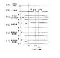
- FIG. 2 to 4 are time charts for explaining an outline of control at the time of fuel cut execution in Embodiment 1 of the present invention.
- the control example shown in FIG. 2 is under the condition where the temperature of the upstream catalyst 36 is lower than the predetermined value ⁇ as shown in FIG.
- the valve stop control is prohibited as shown in FIG. 2 (A), and as shown in FIG. 2 (E).
- the intake air amount accumulation process is started. Further, at this time t1, the integrated fuel injection amount is cleared to zero.
- the intake air amount integration process is stopped. After that, when a fuel cut execution request is issued again at time t3, the intake air amount integration process is started again. Thereafter, when the integrated intake air amount reaches the predetermined value ⁇ at time t4 during the fuel cut accompanied by the prohibition of the valve stop control, the prohibition of the valve stop control is released (that is, the valve stop control is executed). In this case, the integrated intake air amount is cleared to zero. Thereafter, when the fuel cut execution request is turned off at time t5 and fuel injection is resumed, the fuel injection amount integration process is newly started.
- This control example is also under the situation where the temperature of the upstream catalyst 36 is lower than the predetermined value ⁇ as shown in FIG.
- the difference between this control example and the control example shown in FIG. 2 is that the prohibition of the valve stop control is released based on the change in the sub O2 sensor output rather than the change in the integrated intake air amount. That is, in the control example shown in FIG. 3, the sub O2 sensor output is inverted to a lean output of 0.4 V or less in a situation where the integrated intake air amount does not reach the predetermined value ⁇ while the valve stop control is prohibited. (See time t6).
- This control example is different from the above two control examples, and is under the situation where the temperature of the upstream catalyst 36 is the predetermined value ⁇ as shown in FIG. That is, when the catalyst temperature becomes equal to or higher than the predetermined value ⁇ at time t9, as shown in FIG. 4F, the period during which fuel cut is not performed in a state where the valve stop control is not prohibited (from time t10 to time Even at t11), the fuel injection amount integration process is stopped. This makes it difficult to prohibit the valve stop control.
- FIG. 6 is a flowchart showing a routine executed by the ECU 46 in order to realize the fuel injection amount integration process. The processing of this routine is repeatedly executed at every predetermined injection timing.
- the temperature of the upstream catalyst 36 detected by the catalyst temperature sensor 44 is read (step 100).
- the rich poisoning of the upstream catalyst 36 has a characteristic that the upstream catalyst 36 hardly progresses conversely in a high temperature range where the catalyst deterioration is likely to proceed.
- the predetermined value ⁇ in this step 102 is a value set in advance as a threshold value for determining whether or not the temperature of the upstream catalyst 36 is in a temperature range in which such rich poisoning is difficult to proceed.
- the temperature of the upstream catalyst 36 may be obtained by estimation based on the operation history of the internal combustion engine 10, for example, instead of detection by the catalyst temperature sensor 44.
- step 104 it is determined whether or not the valve stop control is being prohibited. Whether or not the valve stop control is prohibited is determined by processing of a main routine shown in FIG.
- the fuel injection amount in the current cycle of the internal combustion engine 10 is read (step 106).
- step 108 a fuel injection amount integration process is executed (step 108). More specifically, the internal combustion engine 10 is basically operated in a state in which the air-fuel ratio is controlled to be the stoichiometric air-fuel ratio. In this step 108, the current fuel injection amount is added to the previous value of the integrated fuel injection amount, whereby the fuel injection amount integration processing under the stoichiometric air-fuel ratio operation is performed.
- step 102 if it is determined in step 102 that the temperature of the upstream catalyst 36 is equal to or higher than the predetermined value ⁇ , the fuel injection amount integration process is not executed, and the current integrated fuel injection amount (current rich fuel amount) is not executed. Poisonous state) is maintained.
- FIG. 7 is a flowchart showing a routine executed by the ECU 46 in order to realize the intake air amount integration process. Note that the processing of this routine is repeatedly executed every predetermined time.
- step 200 it is first determined whether or not a fuel cut is being executed. As a result, when it is determined that the fuel cut is being performed, it is determined whether or not the valve stop control is prohibited (step 202).
- the intake air amount is read using the air flow meter 20 (step 204).
- an intake air amount integration process is executed (step 206). More specifically, the current intake air amount is added to the previous value of the integrated intake air amount.
- the air (fresh air) sucked into the internal combustion engine 10 flows into the upstream catalyst 36 as it is.
- the intake air amount By integrating the intake air amount by the routine shown in FIG. 7, it is possible to grasp the amount of oxygen supplied to the upstream catalyst 36 during the fuel cut accompanied by the prohibition of the valve stop control.
- FIG. 7 is a flowchart showing a main routine executed by the ECU 46. Note that the processing of this routine is repeatedly executed every predetermined time. In the routine shown in FIG. 7, it is first determined whether or not there is a fuel cut execution request (step 300). As a result, when it is determined that there is a fuel cut execution request, it is determined whether or not the valve stop control is prohibited (step 302).
- the integrated fuel injection amount calculated by the subroutine shown in FIG. 6 is read (step 304).
- the predetermined value ⁇ in this step 306 is a value for determining the progress degree of rich poisoning of the upstream catalyst 36 as described above. More specifically, the predetermined value ⁇ is set such that the degree of progress of rich poisoning decreases the purification capacity in order to prevent the rich poisoning from progressing to a level at which a decrease in purification capacity of the upstream catalyst 36 is recognized. It is a value set in advance as a threshold value for determining that the previous predetermined degree of progress has been reached.
- step 306 If the cumulative fuel injection amount ⁇ predetermined value ⁇ is satisfied in step 306, it can be determined that the rich poisoning of the upstream catalyst 36 has progressed, so that valve stop control is prohibited (step 308). Next, the current integrated fuel injection amount is cleared to zero (step 310).
- step 302 determines whether or not the valve stop control is prohibited.
- the current output of the sub O2 sensor 42 is read (step 312).
- step 314 it is determined whether or not the read sub O2 sensor output is a lean output (for example, 0.4 V or less) (step 314).
- the integrated intake air amount calculated by the subroutine shown in FIG. 7 is read (step 316).
- the predetermined value ⁇ in step 318 is a value set in advance as a threshold for determining whether or not the upstream catalyst 36 has recovered from rich poisoning, as described above.
- the valve stop control is continued.
- the prohibition of the valve stop control is released (step 320). That is, execution of valve stop control is permitted.
- the current integrated intake air amount is cleared to zero (step 322).
- step 314 if it is determined in step 314 that the sub O2 sensor output has been reversed to the lean output, it is determined that a sufficient amount of oxygen necessary for recovery from rich poisoning has been supplied to the upstream catalyst 36, and the above step.
- the prohibition of the valve stop control is released without waiting for the determination at 318 (step 320).
- valve stop control when it is determined that the integrated fuel injection amount is equal to or greater than the predetermined value ⁇ at the time of requesting execution of fuel cut, it is determined that rich poisoning has progressed, and fuel cut is performed. It is prohibited to perform valve stop control. That is, oxygen is allowed to flow into the upstream catalyst 36 during the fuel cut.
- valve stop control is basically executed during fuel cut to suppress deterioration of the upstream catalyst 36
- oxygen is supplied to the upstream catalyst 36 for recovery from rich poisoning. Opportunities for supply are secured. For this reason, it is possible to suppress the rich poisoning from progressing to such an extent that the purification capacity of the upstream catalyst 36 decreases.
- the progress of rich poisoning due to continued theoretical air-fuel ratio operation correlates with the integrated value of the supplied fuel amount. According to the above routine, it is possible to accurately prevent the progress of rich poisoning by determining whether or not the valve stop control is prohibited based on such an integrated fuel injection amount. Further, according to the above routine, it is possible to accurately determine the release timing of the prohibition of the valve stop control based on the integrated value of the supply oxygen amount (supply air amount) correlated with the recovery of rich poisoning.
- the fuel injection amount integration process is stopped when the temperature of the upstream catalyst 36 is equal to or higher than the predetermined value ⁇ .
- the prohibition of the valve stop control for suppressing the progress of the rich poisoning is difficult to be executed, and the oxygen supply to the upstream catalyst 36 is restricted.
- the rich poisoning of the upstream catalyst 36 has a characteristic that it does not easily proceed in the high temperature range where the catalyst deterioration is likely to proceed. Therefore, according to the routine shown in FIG. 6, it is possible to satisfactorily achieve both the suppression of catalyst deterioration and the suppression of the progress of rich poisoning in a high temperature range of the catalyst.
- the upstream catalyst 36 is rich when the integrated intake air amount is equal to or greater than the predetermined value ⁇ . Judging from the poison.
- the method for determining whether or not the rich poisoning of the catalyst has progressed in the present invention is not limited to this.
- the poisoning correlation value in the present invention may be, for example, the operation time of the internal combustion engine 10 under the theoretical air-fuel ratio control, instead of the integrated fuel injection amount. Further, the poisoning correlation value may be, for example, the operation time of the internal combustion engine 10 during the fuel cut with the prohibition of the valve stop control instead of the integrated intake air amount. Further, instead of the above determination method, even if it is determined that the rich poisoning of the upstream catalyst 36 has progressed when the output of the sub O2 sensor 42 does not show a lean output for a predetermined period during the theoretical air-fuel ratio operation. Good.
- the operation state of both the intake valve 28 and the exhaust valve 30 is switched to the closed valve stop state when the valve stop control is performed during the fuel cut. Went.
- the operating states of both the intake valve 28 and the exhaust valve 30 are not switched to the closed valve stop state. In other words, the operating state of only one of the intake valve 28 and the exhaust valve 30 may be switched to the closed valve stop state.
- the valve when the integrated fuel injection amount is equal to or greater than the predetermined value ⁇ when the fuel cut is requested, the valve is subsequently operated until the integrated intake air amount becomes equal to or greater than the predetermined value ⁇ . Stop control is prohibited.
- the present invention is not limited to this. That is, for example, when the integrated fuel injection amount is equal to or greater than the predetermined value ⁇ when a fuel cut execution request is made, an opportunity for prohibiting valve stop (upstream catalyst) at the start of fuel cut is delayed by delaying the start timing of valve stop control. Control to ensure the opportunity to supply oxygen to 36) may be performed.
- the return time from the fuel cut is predicted in advance, as in the case of the fuel cut in which the return from the fuel cut (so-called natural return) is made.
- the following control may be performed, for example, when the integrated fuel injection amount is equal to or greater than the predetermined value ⁇ when a fuel cut execution request is made. That is, by returning the operating state of the intake and exhaust valves 28 and 30 to the valve operating state prior to resuming fuel injection when returning from the fuel cut, the valve stop prohibition opportunity (upstream catalyst 36) immediately before returning from the fuel cut. It is also possible to perform control to ensure an opportunity to supply oxygen to the gas.
- the valve stop control is prohibited so that oxygen flows into the upstream catalyst 36.
- the oxygen supply method in the present invention is not limited to the supply of intake air that has passed through the combustion chamber 14 as described above. That is, for example, a secondary air supply path for the upstream catalyst 36 may be provided to supply oxygen from the outside.
- a secondary air supply path for the upstream catalyst 36 may be provided to supply oxygen from the outside.
- the rotation of the internal combustion engine 10 is stopped when the fuel cut is performed. If so, oxygen may be supplied to the catalyst by driving (pumping) the internal combustion engine with a motor while prohibiting the valve stop control of the intake / exhaust valve during the fuel cut.
- oxygen is supplied to the catalyst 36 by prohibiting the valve stop control. I am doing so.
- the present invention is not limited to this.
- oxygen may be supplied to the catalyst. .
- valve stop mechanism provided in the intake variable valve operating apparatus 32 and the exhaust variable valve operating apparatus 34 corresponds to the “valve stop mechanism” in the first invention, and the ECU 46
- the fuel injection by the in-cylinder fuel injection valve 24 is stopped so that the “fuel cut execution means” uses the variable valve operating devices 32 and 34 at the time of fuel cut execution request.
- the “valve stop execution means” in the first invention executes the processing of the routine shown in FIG. 5 to perform the “poisoning correlation” in the first invention.
- the “value acquisition means” executes the processing of steps 304 and 306, so that the “poisoning determination means” in the first aspect of the present invention performs the step during fuel cut.
- "Oxygen supply means” of the invention by executing the process of flop 308 is implemented respectively.
- the “valve stop prohibiting means” in the second aspect of the present invention is realized by the ECU 46 executing the processing of step 308.
- the “catalyst temperature acquisition means” in the sixth aspect of the invention stops the fuel injection amount integration process when the determination of step 102 is not established.
- “oxygen supply limiting means” is realized.
- the “poisoning recovery determination means” in the eighth invention executes the processing of the above step 320 to execute the above eighth step.
- the “valve stop prohibition releasing means” in the invention is realized respectively.
- the “air-fuel ratio detecting means” according to the tenth aspect of the present invention is implemented by the ECU 46 executing the processing of step 312.
Landscapes
- Engineering & Computer Science (AREA)
- Chemical & Material Sciences (AREA)
- Combustion & Propulsion (AREA)
- Mechanical Engineering (AREA)
- General Engineering & Computer Science (AREA)
- Electrical Control Of Air Or Fuel Supplied To Internal-Combustion Engine (AREA)
- Combined Controls Of Internal Combustion Engines (AREA)
- Exhaust Gas After Treatment (AREA)
- Output Control And Ontrol Of Special Type Engine (AREA)
Abstract
Description
尚、出願人は、本発明に関連するものとして、上記の文献を含めて、以下に記載する文献を認識している。
吸気弁および排気弁の少なくとも一方の弁の動作状態を弁稼動状態と閉弁停止状態との間で変更可能な弁停止機構と、
内燃機関の運転中に、所定の実行条件が成立した場合にフューエルカットを実行するフューエルカット実行手段と、
前記フューエルカットの実行時に、前記少なくとも一方の弁の動作状態を前記閉弁停止状態に変更する弁停止制御を行う弁停止実行手段と、
前記内燃機関の排気通路に配置された触媒のリッチ被毒の進行と相関を有する被毒相関値を取得する被毒相関値取得手段と、
前記被毒相関値に基づいて、前記触媒のリッチ被毒が進行したか否かを判断する被毒判断手段と、
前記フューエルカットの実行時に、前記触媒の前記リッチ被毒が進行した状態にあると判断された場合に、前記触媒に酸素を供給する酸素供給手段と、
を備えることを特徴とする。
前記酸素供給手段は、前記弁停止実行手段による前記弁停止制御を禁止する弁停止禁止手段を含むことを特徴とする。
前記被毒相関値は、積算燃料噴射量であり、
前記弁停止禁止手段は、前記フューエルカットの実行要求が検知された時に前記積算燃料噴射量が所定値以上である場合に、前記弁停止制御を禁止することを特徴とする。
前記被毒相関値は、積算燃料噴射量であり、
前記弁停止禁止手段は、前記フューエルカットの実行要求が検知された時に前記積算燃料噴射量が所定値以上である場合に、前記弁停止制御の開始時期を遅らせることを特徴とする。
前記被毒相関値は、積算燃料噴射量であり、
前記弁停止禁止手段は、前記フューエルカットの実行要求が検知された時に前記積算燃料噴射量が所定値以上である場合に、前記フューエルカットからの復帰時の燃料供給再開に先立って、前記閉弁停止状態にある前記少なくとも一方の弁の動作状態を前記弁稼動状態に復帰させることを特徴とする。
前記触媒の温度を取得する触媒温度取得手段と、
前記触媒の温度が所定値以上である場合に、前記酸素供給手段による前記触媒への酸素供給を制限する酸素供給制限手段と、
を更に備えることを特徴とする。
前記酸素供給制限手段は、前記触媒の温度が前記所定値以上である場合に、前記被毒相関値取得手段による燃料噴射量の積算処理を中止する手段であることを特徴とする。
前記被毒判断手段は、前記弁停止禁止手段による前記弁停止制御の禁止中に、前記触媒が前記リッチ被毒から回復したか否かを判断する被毒回復判断手段を含み、
前記内燃機関の制御装置は、前記触媒が前記リッチ被毒から回復したと判断された場合に、前記弁停止禁止手段による前記弁停止制御の禁止を解除する弁停止禁止解除手段を更に備えることを特徴とする。
前記被毒回復判断手段は、前記弁停止制御の禁止を伴うフューエルカット中に、前記内燃機関の吸入空気量の積算値が所定値以上である場合に、前記触媒が前記リッチ被毒から回復したと判断することを特徴とする。
前記触媒よりも下流側の前記排気通路に配置され、排気ガスの空燃比を検出する空燃比検出手段を更に備え、
前記被毒回復判断手段は、前記弁停止制御の禁止中に、前記空燃比検出手段により検出される前記触媒の下流の排気ガスの空燃比が理論空燃比よりもリーンになった場合に、前記触媒が前記リッチ被毒から回復したと判断することを特徴とする。
14 燃焼室
16 吸気通路
18 排気通路
20 エアフローメータ
22 スロットルバルブ
24 筒内燃料噴射弁
28 吸気弁
30 排気弁
32 吸気可変動弁装置
34 排気可変動弁装置
36 上流触媒(SC)
38 下流触媒(UFC)
40 メイン空燃比センサ
42 サブO2センサ
44 触媒温度センサ
46 ECU(Electronic Control Unit)
[システム構成の説明]
図1は、本発明の実施の形態1の内燃機関10の構成を説明するための図である。本実施形態のシステムは、内燃機関10を備えている。内燃機関10の筒内には、ピストン12が設けられている。内燃機関10の筒内には、ピストン12の頂部側に燃焼室14が形成されている。燃焼室14には、吸気通路16および排気通路18が連通している。
排気通路18に配置される上流触媒36が高温状態にある場合に、酸素濃度の高い新気が上流触媒36に供給されると、上流触媒36に劣化が生ずることが懸念される。上流触媒36の劣化を抑制するためには、上流触媒36への酸素の流入を防ぐことが有効である。上述した可変動弁装置32、34を備える本実施形態のシステムによれば、減速時等においてフューエルカット(F/C)の実行要求が出された場合に、吸気弁28および排気弁30の動作状態をそれぞれ閉弁停止状態とすることで、フューエルカット中に上流触媒36に酸素が流入するのを防止することができる。
図2に示す制御例は、図2(D)に示すように上流触媒36の温度が上記所定値τより低い状況下でのものである。図2に示す制御例では、時刻t0において積算燃料噴射量が上記所定値β以上となった場合に、上流触媒36のリッチ被毒が進行したと判断される。その結果、その後の時刻t1において、フューエルカットの実行要求が出された際に、図2(A)に示すように弁停止制御の禁止が実行されるとともに、図2(E)に示すように吸入空気量の積算処理が開始される。また、この時刻t1において、積算燃料噴射量がゼロにクリアされる。
次に、図5乃至図7を参照して、上述した本実施形態の制御の具体的な処理内容について説明する。
先ず、燃料噴射量の積算処理について説明する。図6は、燃料噴射量の積算処理を実現するために、ECU46が実行するルーチンを示すフローチャートである。尚、本ルーチンの処理は、所定の噴射タイミング毎に繰り返し実行されるものである。
図7に示すルーチンでは、先ず、フューエルカットの実行要求があるか否かが判定される(ステップ300)。その結果、フューエルカットの実行要求があると判定された場合には、弁停止制御の禁止中であるか否かが判定される(ステップ302)。
更には、エンジン回転数が所定の復帰回転数に達した場合にフューエルカットからの復帰(いわゆる自然復帰)がなされる態様のフューエルカットの場合のように、フューエルカットからの復帰時期を事前に予測できる場合であれば、フューエルカットの実行要求時に積算燃料噴射量が上記所定値β以上である場合に、例えば、以下のような制御を行うようにしてもよい。すなわち、フューエルカットからの復帰時の燃料噴射再開に先立って吸排気弁28、30の動作状態を弁稼動状態に復帰させることで、フューエルカットからの復帰直前において弁停止禁止の機会(上流触媒36に酸素を供給する機会)を確保する制御を行うものであってもよい。
また、ECU46が上記ステップ308の処理を実行することにより、前記第2の発明における「弁停止禁止手段」が実現されている。
また、ECU46が、上記ステップ100の処理を実行することにより前記第6の発明における「触媒温度取得手段」が、上記ステップ102の判定が不成立である場合に燃料噴射量の積算処理を中止することにより「酸素供給制限手段」が、それぞれ実現されている。
また、ECU46が、上記ステップ312~314または316~318の処理を実行することにより前記第8の発明における「被毒回復判断手段」が、上記ステップ320の処理を実行することにより前記第8の発明における「弁停止禁止解除手段」が、それぞれ実現されている。
また、ECU46が上記ステップ312の処理を実行することにより、前記第10の発明における「空燃比検出手段」が実現されている。
Claims (10)
- 吸気弁および排気弁の少なくとも一方の弁の動作状態を弁稼動状態と閉弁停止状態との間で変更可能な弁停止機構と、
内燃機関の運転中に、所定の実行条件が成立した場合にフューエルカットを実行するフューエルカット実行手段と、
前記フューエルカットの実行時に、前記少なくとも一方の弁の動作状態を前記閉弁停止状態に変更する弁停止制御を行う弁停止実行手段と、
前記内燃機関の排気通路に配置された触媒のリッチ被毒の進行と相関を有する被毒相関値を取得する被毒相関値取得手段と、
前記被毒相関値に基づいて、前記触媒のリッチ被毒が進行したか否かを判断する被毒判断手段と、
前記フューエルカットの実行時に、前記触媒の前記リッチ被毒が進行した状態にあると判断された場合に、前記触媒に酸素を供給する酸素供給手段と、
を備えることを特徴とする内燃機関の制御装置。 - 前記酸素供給手段は、前記弁停止実行手段による前記弁停止制御を禁止する弁停止禁止手段を含むことを特徴とする請求項1記載の内燃機関の制御装置。
- 前記被毒相関値は、積算燃料噴射量であり、
前記弁停止禁止手段は、前記フューエルカットの実行要求が検知された時に前記積算燃料噴射量が所定値以上である場合に、前記弁停止制御を禁止することを特徴とする請求項2記載の内燃機関の制御装置。 - 前記被毒相関値は、積算燃料噴射量であり、
前記弁停止禁止手段は、前記フューエルカットの実行要求が検知された時に前記積算燃料噴射量が所定値以上である場合に、前記弁停止制御の開始時期を遅らせることを特徴とする請求項1記載の内燃機関の制御装置。 - 前記被毒相関値は、積算燃料噴射量であり、
前記弁停止禁止手段は、前記フューエルカットの実行要求が検知された時に前記積算燃料噴射量が所定値以上である場合に、前記フューエルカットからの復帰時の燃料供給再開に先立って、前記閉弁停止状態にある前記少なくとも一方の弁の動作状態を前記弁稼動状態に復帰させることを特徴とする請求項1記載の内燃機関の制御装置。 - 前記触媒の温度を取得する触媒温度取得手段と、
前記触媒の温度が所定値以上である場合に、前記酸素供給手段による前記触媒への酸素供給を制限する酸素供給制限手段と、
を更に備えることを特徴とする請求項3乃至5の何れか1項記載の内燃機関の制御装置。 - 前記酸素供給制限手段は、前記触媒の温度が前記所定値以上である場合に、前記被毒相関値取得手段による燃料噴射量の積算処理を中止する手段であることを特徴とする請求項6記載の内燃機関の制御装置。
- 前記被毒判断手段は、前記弁停止禁止手段による前記弁停止制御の禁止中に、前記触媒が前記リッチ被毒から回復したか否かを判断する被毒回復判断手段を含み、
前記内燃機関の制御装置は、前記触媒が前記リッチ被毒から回復したと判断された場合に、前記弁停止禁止手段による前記弁停止制御の禁止を解除する弁停止禁止解除手段を更に備えることを特徴とする請求項2乃至7の何れか1項記載の内燃機関の制御装置。 - 前記被毒回復判断手段は、前記弁停止制御の禁止を伴うフューエルカット中に、前記内燃機関の吸入空気量の積算値が所定値以上である場合に、前記触媒が前記リッチ被毒から回復したと判断することを特徴とする請求項8記載の内燃機関の制御装置。
- 前記触媒よりも下流側の前記排気通路に配置され、排気ガスの空燃比を検出する空燃比検出手段を更に備え、
前記被毒回復判断手段は、前記弁停止制御の禁止中に、前記空燃比検出手段により検出される前記触媒の下流の排気ガスの空燃比が理論空燃比よりもリーンになった場合に、前記触媒が前記リッチ被毒から回復したと判断することを特徴とする請求項8記載の内燃機関の制御装置。
Priority Applications (5)
| Application Number | Priority Date | Filing Date | Title |
|---|---|---|---|
| EP10846980.0A EP2543854B1 (en) | 2010-03-02 | 2010-03-02 | Control device for internal combustion engine |
| US13/522,462 US8806856B2 (en) | 2010-03-02 | 2010-03-02 | Control apparatus for internal combustion engine |
| CN2010800646555A CN102770640B (zh) | 2010-03-02 | 2010-03-02 | 内燃机的控制装置 |
| PCT/JP2010/053333 WO2011108075A1 (ja) | 2010-03-02 | 2010-03-02 | 内燃機関の制御装置 |
| JP2012502916A JP5187458B2 (ja) | 2010-03-02 | 2010-03-02 | 内燃機関の制御装置 |
Applications Claiming Priority (1)
| Application Number | Priority Date | Filing Date | Title |
|---|---|---|---|
| PCT/JP2010/053333 WO2011108075A1 (ja) | 2010-03-02 | 2010-03-02 | 内燃機関の制御装置 |
Publications (1)
| Publication Number | Publication Date |
|---|---|
| WO2011108075A1 true WO2011108075A1 (ja) | 2011-09-09 |
Family
ID=44541761
Family Applications (1)
| Application Number | Title | Priority Date | Filing Date |
|---|---|---|---|
| PCT/JP2010/053333 Ceased WO2011108075A1 (ja) | 2010-03-02 | 2010-03-02 | 内燃機関の制御装置 |
Country Status (5)
| Country | Link |
|---|---|
| US (1) | US8806856B2 (ja) |
| EP (1) | EP2543854B1 (ja) |
| JP (1) | JP5187458B2 (ja) |
| CN (1) | CN102770640B (ja) |
| WO (1) | WO2011108075A1 (ja) |
Families Citing this family (8)
| Publication number | Priority date | Publication date | Assignee | Title |
|---|---|---|---|---|
| EP2955346B8 (en) * | 2013-02-08 | 2018-10-17 | Toyota Jidosha Kabushiki Kaisha | Exhaust purification apparatus for internal combustion engine |
| DE102014208915A1 (de) * | 2014-05-12 | 2015-11-12 | Robert Bosch Gmbh | Verfahren zum Betreiben einer Brennkraftmaschine eines Kraftfahrzeugs im Schubbetrieb bei niedrigen Emissionen und geringem Kraftstoffverbrauch |
| US9988997B2 (en) * | 2014-10-22 | 2018-06-05 | Ford Global Technologies, Llc | Method and system for engine temperature control |
| KR101619248B1 (ko) * | 2014-12-02 | 2016-05-10 | 현대자동차 주식회사 | 하이브리드 차량의 배기 가스 촉매 활성화 장치 및 방법 |
| JP6946871B2 (ja) * | 2017-09-05 | 2021-10-13 | トヨタ自動車株式会社 | 内燃機関の制御システム |
| US10634078B2 (en) * | 2017-12-11 | 2020-04-28 | Ford Global Technologies, Llc | Methods and systems for an exhaust aftertreatment device |
| JP7107080B2 (ja) * | 2018-08-07 | 2022-07-27 | トヨタ自動車株式会社 | 内燃機関の制御装置 |
| JP7176448B2 (ja) * | 2019-03-18 | 2022-11-22 | トヨタ自動車株式会社 | 車両の制御装置 |
Citations (7)
| Publication number | Priority date | Publication date | Assignee | Title |
|---|---|---|---|---|
| JPH0531320A (ja) * | 1991-07-31 | 1993-02-09 | Nissan Motor Co Ltd | 内燃機関の排気浄化装置 |
| JPH08158857A (ja) * | 1994-12-06 | 1996-06-18 | Nissan Motor Co Ltd | 内燃機関における排気浄化触媒の性能回復装置 |
| JP2001182570A (ja) * | 1999-12-24 | 2001-07-06 | Toyota Motor Corp | 可変動弁機構を有する内燃機関 |
| JP2003074385A (ja) * | 2001-08-31 | 2003-03-12 | Honda Motor Co Ltd | 内燃機関の制御装置 |
| JP2003307122A (ja) * | 2003-05-08 | 2003-10-31 | Nissan Motor Co Ltd | 内燃機関における排気浄化触媒の性能回復装置 |
| JP2004169646A (ja) * | 2002-11-21 | 2004-06-17 | Toyota Motor Corp | 可変動弁機構を有する内燃機関 |
| JP2009103017A (ja) * | 2007-10-22 | 2009-05-14 | Toyota Motor Corp | 内燃機関の制御装置 |
Family Cites Families (9)
| Publication number | Priority date | Publication date | Assignee | Title |
|---|---|---|---|---|
| DE19606584C2 (de) | 1995-04-19 | 1997-07-31 | Porsche Ag | Verfahren zur Zylinderabschaltung einer Brennkraftmaschine |
| JP3801783B2 (ja) | 1998-07-16 | 2006-07-26 | 本田技研工業株式会社 | 休筒式エンジンの制御装置 |
| JP3583324B2 (ja) | 1999-09-22 | 2004-11-04 | 本田技研工業株式会社 | 内燃機関の制御装置 |
| JP3695397B2 (ja) * | 2001-04-10 | 2005-09-14 | トヨタ自動車株式会社 | 内燃機関の排気浄化装置 |
| US6892527B2 (en) * | 2002-07-16 | 2005-05-17 | Mitsubishi Jidosha Kogyo Kabushiki Kaisha | Catalyst deterioration suppressing apparatus and method |
| JP4207965B2 (ja) * | 2006-02-10 | 2009-01-14 | トヨタ自動車株式会社 | 内燃機関の制御装置 |
| JP5217102B2 (ja) * | 2006-03-24 | 2013-06-19 | いすゞ自動車株式会社 | NOx浄化システムの制御方法及びNOx浄化システム |
| JP4765777B2 (ja) * | 2006-06-01 | 2011-09-07 | トヨタ自動車株式会社 | 内燃機関および内燃機関の運転方法 |
| DE602007011241D1 (de) * | 2007-06-19 | 2011-01-27 | Ford Global Tech Llc | Hybridfahrzeug, Antriebssystem für ein Hybridfahrzeug und Verfahren für eine Abgasverarbeitungsvorrichtung in einem solchen System |
-
2010
- 2010-03-02 US US13/522,462 patent/US8806856B2/en not_active Expired - Fee Related
- 2010-03-02 JP JP2012502916A patent/JP5187458B2/ja not_active Expired - Fee Related
- 2010-03-02 WO PCT/JP2010/053333 patent/WO2011108075A1/ja not_active Ceased
- 2010-03-02 EP EP10846980.0A patent/EP2543854B1/en not_active Not-in-force
- 2010-03-02 CN CN2010800646555A patent/CN102770640B/zh not_active Expired - Fee Related
Patent Citations (7)
| Publication number | Priority date | Publication date | Assignee | Title |
|---|---|---|---|---|
| JPH0531320A (ja) * | 1991-07-31 | 1993-02-09 | Nissan Motor Co Ltd | 内燃機関の排気浄化装置 |
| JPH08158857A (ja) * | 1994-12-06 | 1996-06-18 | Nissan Motor Co Ltd | 内燃機関における排気浄化触媒の性能回復装置 |
| JP2001182570A (ja) * | 1999-12-24 | 2001-07-06 | Toyota Motor Corp | 可変動弁機構を有する内燃機関 |
| JP2003074385A (ja) * | 2001-08-31 | 2003-03-12 | Honda Motor Co Ltd | 内燃機関の制御装置 |
| JP2004169646A (ja) * | 2002-11-21 | 2004-06-17 | Toyota Motor Corp | 可変動弁機構を有する内燃機関 |
| JP2003307122A (ja) * | 2003-05-08 | 2003-10-31 | Nissan Motor Co Ltd | 内燃機関における排気浄化触媒の性能回復装置 |
| JP2009103017A (ja) * | 2007-10-22 | 2009-05-14 | Toyota Motor Corp | 内燃機関の制御装置 |
Non-Patent Citations (1)
| Title |
|---|
| See also references of EP2543854A4 * |
Also Published As
| Publication number | Publication date |
|---|---|
| CN102770640B (zh) | 2013-07-24 |
| US8806856B2 (en) | 2014-08-19 |
| EP2543854B1 (en) | 2014-04-30 |
| US20120291423A1 (en) | 2012-11-22 |
| JP5187458B2 (ja) | 2013-04-24 |
| CN102770640A (zh) | 2012-11-07 |
| EP2543854A1 (en) | 2013-01-09 |
| JPWO2011108075A1 (ja) | 2013-06-20 |
| EP2543854A4 (en) | 2013-06-05 |
Similar Documents
| Publication | Publication Date | Title |
|---|---|---|
| JP5187458B2 (ja) | 内燃機関の制御装置 | |
| CN102282351B (zh) | 内燃机的控制装置 | |
| JP5052547B2 (ja) | 内燃機関、内燃機関の制御装置 | |
| JP5240370B2 (ja) | 内燃機関の制御装置 | |
| JP5868073B2 (ja) | 内燃機関の制御装置 | |
| JP5321747B2 (ja) | ハイブリッド車両の制御装置 | |
| JP2016223392A (ja) | エンジンの制御装置 | |
| WO2010106842A1 (ja) | エンジンの制御装置 | |
| JP4375271B2 (ja) | 内燃機関の制御装置 | |
| JP2013160156A (ja) | 内燃機関の故障判定装置および車両 | |
| JP2005330886A (ja) | エンジンのアイドル停止制御装置 | |
| JP5392021B2 (ja) | 内燃機関の燃料噴射制御装置 | |
| JP2010265802A (ja) | 内燃機関の排ガス浄化装置 | |
| JP2008151025A (ja) | 内燃機関の制御装置 | |
| JP2011157906A (ja) | 内燃機関の制御装置 | |
| JP2012251461A (ja) | 空燃比検出装置の故障判定装置 | |
| JP5074717B2 (ja) | 内燃機関の燃料噴射制御装置 | |
| JP6287175B2 (ja) | エンジンの制御装置 | |
| JP6298330B2 (ja) | エンジン制御装置 | |
| JP5164619B2 (ja) | 内燃機関の運転制御方法 | |
| JP2012159003A (ja) | 内燃機関の制御方法 | |
| JP2002089331A (ja) | 内燃機関の制御装置 | |
| JP2009264215A (ja) | 内燃機関の制御装置 | |
| JP2006348753A (ja) | エンジンの排ガス浄化装置 | |
| JP2008025506A (ja) | 内燃機関の制御装置 |
Legal Events
| Date | Code | Title | Description |
|---|---|---|---|
| WWE | Wipo information: entry into national phase |
Ref document number: 201080064655.5 Country of ref document: CN |
|
| 121 | Ep: the epo has been informed by wipo that ep was designated in this application |
Ref document number: 10846980 Country of ref document: EP Kind code of ref document: A1 |
|
| WWE | Wipo information: entry into national phase |
Ref document number: 2012502916 Country of ref document: JP |
|
| WWE | Wipo information: entry into national phase |
Ref document number: 2010846980 Country of ref document: EP |
|
| WWE | Wipo information: entry into national phase |
Ref document number: 13522462 Country of ref document: US |
|
| NENP | Non-entry into the national phase |
Ref country code: DE |