WO2011108110A1 - 内燃機関の排気浄化装置 - Google Patents
内燃機関の排気浄化装置 Download PDFInfo
- Publication number
- WO2011108110A1 WO2011108110A1 PCT/JP2010/053631 JP2010053631W WO2011108110A1 WO 2011108110 A1 WO2011108110 A1 WO 2011108110A1 JP 2010053631 W JP2010053631 W JP 2010053631W WO 2011108110 A1 WO2011108110 A1 WO 2011108110A1
- Authority
- WO
- WIPO (PCT)
- Prior art keywords
- additive
- liquid
- gas
- internal combustion
- combustion engine
- Prior art date
- Legal status (The legal status is an assumption and is not a legal conclusion. Google has not performed a legal analysis and makes no representation as to the accuracy of the status listed.)
- Ceased
Links
Images






Classifications
-
- F—MECHANICAL ENGINEERING; LIGHTING; HEATING; WEAPONS; BLASTING
- F01—MACHINES OR ENGINES IN GENERAL; ENGINE PLANTS IN GENERAL; STEAM ENGINES
- F01N—GAS-FLOW SILENCERS OR EXHAUST APPARATUS FOR MACHINES OR ENGINES IN GENERAL; GAS-FLOW SILENCERS OR EXHAUST APPARATUS FOR INTERNAL-COMBUSTION ENGINES
- F01N3/00—Exhaust or silencing apparatus having means for purifying, rendering innocuous, or otherwise treating exhaust
- F01N3/08—Exhaust or silencing apparatus having means for purifying, rendering innocuous, or otherwise treating exhaust for rendering innocuous
- F01N3/10—Exhaust or silencing apparatus having means for purifying, rendering innocuous, or otherwise treating exhaust for rendering innocuous by thermal or catalytic conversion of noxious components of exhaust
- F01N3/18—Exhaust or silencing apparatus having means for purifying, rendering innocuous, or otherwise treating exhaust for rendering innocuous by thermal or catalytic conversion of noxious components of exhaust characterised by methods of operation; Control
- F01N3/20—Exhaust or silencing apparatus having means for purifying, rendering innocuous, or otherwise treating exhaust for rendering innocuous by thermal or catalytic conversion of noxious components of exhaust characterised by methods of operation; Control specially adapted for catalytic conversion
- F01N3/206—Adding periodically or continuously substances to exhaust gases for promoting purification, e.g. catalytic material in liquid form, NOx reducing agents
- F01N3/2066—Selective catalytic reduction [SCR]
-
- F—MECHANICAL ENGINEERING; LIGHTING; HEATING; WEAPONS; BLASTING
- F01—MACHINES OR ENGINES IN GENERAL; ENGINE PLANTS IN GENERAL; STEAM ENGINES
- F01N—GAS-FLOW SILENCERS OR EXHAUST APPARATUS FOR MACHINES OR ENGINES IN GENERAL; GAS-FLOW SILENCERS OR EXHAUST APPARATUS FOR INTERNAL-COMBUSTION ENGINES
- F01N3/00—Exhaust or silencing apparatus having means for purifying, rendering innocuous, or otherwise treating exhaust
- F01N3/08—Exhaust or silencing apparatus having means for purifying, rendering innocuous, or otherwise treating exhaust for rendering innocuous
- F01N3/0807—Exhaust or silencing apparatus having means for purifying, rendering innocuous, or otherwise treating exhaust for rendering innocuous by using absorbents or adsorbents
- F01N3/0814—Exhaust or silencing apparatus having means for purifying, rendering innocuous, or otherwise treating exhaust for rendering innocuous by using absorbents or adsorbents combined with catalytic converters, e.g. NOx absorption/storage reduction catalysts
-
- F—MECHANICAL ENGINEERING; LIGHTING; HEATING; WEAPONS; BLASTING
- F01—MACHINES OR ENGINES IN GENERAL; ENGINE PLANTS IN GENERAL; STEAM ENGINES
- F01N—GAS-FLOW SILENCERS OR EXHAUST APPARATUS FOR MACHINES OR ENGINES IN GENERAL; GAS-FLOW SILENCERS OR EXHAUST APPARATUS FOR INTERNAL-COMBUSTION ENGINES
- F01N3/00—Exhaust or silencing apparatus having means for purifying, rendering innocuous, or otherwise treating exhaust
- F01N3/08—Exhaust or silencing apparatus having means for purifying, rendering innocuous, or otherwise treating exhaust for rendering innocuous
- F01N3/10—Exhaust or silencing apparatus having means for purifying, rendering innocuous, or otherwise treating exhaust for rendering innocuous by thermal or catalytic conversion of noxious components of exhaust
- F01N3/18—Exhaust or silencing apparatus having means for purifying, rendering innocuous, or otherwise treating exhaust for rendering innocuous by thermal or catalytic conversion of noxious components of exhaust characterised by methods of operation; Control
- F01N3/20—Exhaust or silencing apparatus having means for purifying, rendering innocuous, or otherwise treating exhaust for rendering innocuous by thermal or catalytic conversion of noxious components of exhaust characterised by methods of operation; Control specially adapted for catalytic conversion
- F01N3/206—Adding periodically or continuously substances to exhaust gases for promoting purification, e.g. catalytic material in liquid form, NOx reducing agents
- F01N3/208—Control of selective catalytic reduction [SCR], e.g. by adjusting the dosing of reducing agent
-
- F—MECHANICAL ENGINEERING; LIGHTING; HEATING; WEAPONS; BLASTING
- F01—MACHINES OR ENGINES IN GENERAL; ENGINE PLANTS IN GENERAL; STEAM ENGINES
- F01N—GAS-FLOW SILENCERS OR EXHAUST APPARATUS FOR MACHINES OR ENGINES IN GENERAL; GAS-FLOW SILENCERS OR EXHAUST APPARATUS FOR INTERNAL-COMBUSTION ENGINES
- F01N9/00—Electrical control of exhaust gas treating apparatus
-
- F—MECHANICAL ENGINEERING; LIGHTING; HEATING; WEAPONS; BLASTING
- F01—MACHINES OR ENGINES IN GENERAL; ENGINE PLANTS IN GENERAL; STEAM ENGINES
- F01N—GAS-FLOW SILENCERS OR EXHAUST APPARATUS FOR MACHINES OR ENGINES IN GENERAL; GAS-FLOW SILENCERS OR EXHAUST APPARATUS FOR INTERNAL-COMBUSTION ENGINES
- F01N2610/00—Adding substances to exhaust gases
- F01N2610/01—Adding substances to exhaust gases the substance being catalytic material in liquid form
-
- F—MECHANICAL ENGINEERING; LIGHTING; HEATING; WEAPONS; BLASTING
- F01—MACHINES OR ENGINES IN GENERAL; ENGINE PLANTS IN GENERAL; STEAM ENGINES
- F01N—GAS-FLOW SILENCERS OR EXHAUST APPARATUS FOR MACHINES OR ENGINES IN GENERAL; GAS-FLOW SILENCERS OR EXHAUST APPARATUS FOR INTERNAL-COMBUSTION ENGINES
- F01N2610/00—Adding substances to exhaust gases
- F01N2610/02—Adding substances to exhaust gases the substance being ammonia or urea
-
- F—MECHANICAL ENGINEERING; LIGHTING; HEATING; WEAPONS; BLASTING
- F01—MACHINES OR ENGINES IN GENERAL; ENGINE PLANTS IN GENERAL; STEAM ENGINES
- F01N—GAS-FLOW SILENCERS OR EXHAUST APPARATUS FOR MACHINES OR ENGINES IN GENERAL; GAS-FLOW SILENCERS OR EXHAUST APPARATUS FOR INTERNAL-COMBUSTION ENGINES
- F01N2610/00—Adding substances to exhaust gases
- F01N2610/06—Adding substances to exhaust gases the substance being in the gaseous form
-
- F—MECHANICAL ENGINEERING; LIGHTING; HEATING; WEAPONS; BLASTING
- F01—MACHINES OR ENGINES IN GENERAL; ENGINE PLANTS IN GENERAL; STEAM ENGINES
- F01N—GAS-FLOW SILENCERS OR EXHAUST APPARATUS FOR MACHINES OR ENGINES IN GENERAL; GAS-FLOW SILENCERS OR EXHAUST APPARATUS FOR INTERNAL-COMBUSTION ENGINES
- F01N3/00—Exhaust or silencing apparatus having means for purifying, rendering innocuous, or otherwise treating exhaust
- F01N3/02—Exhaust or silencing apparatus having means for purifying, rendering innocuous, or otherwise treating exhaust for cooling, or for removing solid constituents of, exhaust
- F01N3/021—Exhaust or silencing apparatus having means for purifying, rendering innocuous, or otherwise treating exhaust for cooling, or for removing solid constituents of, exhaust by means of filters
- F01N3/033—Exhaust or silencing apparatus having means for purifying, rendering innocuous, or otherwise treating exhaust for cooling, or for removing solid constituents of, exhaust by means of filters in combination with other devices
- F01N3/035—Exhaust or silencing apparatus having means for purifying, rendering innocuous, or otherwise treating exhaust for cooling, or for removing solid constituents of, exhaust by means of filters in combination with other devices with catalytic reactors
-
- Y—GENERAL TAGGING OF NEW TECHNOLOGICAL DEVELOPMENTS; GENERAL TAGGING OF CROSS-SECTIONAL TECHNOLOGIES SPANNING OVER SEVERAL SECTIONS OF THE IPC; TECHNICAL SUBJECTS COVERED BY FORMER USPC CROSS-REFERENCE ART COLLECTIONS [XRACs] AND DIGESTS
- Y02—TECHNOLOGIES OR APPLICATIONS FOR MITIGATION OR ADAPTATION AGAINST CLIMATE CHANGE
- Y02T—CLIMATE CHANGE MITIGATION TECHNOLOGIES RELATED TO TRANSPORTATION
- Y02T10/00—Road transport of goods or passengers
- Y02T10/10—Internal combustion engine [ICE] based vehicles
- Y02T10/12—Improving ICE efficiencies
-
- Y—GENERAL TAGGING OF NEW TECHNOLOGICAL DEVELOPMENTS; GENERAL TAGGING OF CROSS-SECTIONAL TECHNOLOGIES SPANNING OVER SEVERAL SECTIONS OF THE IPC; TECHNICAL SUBJECTS COVERED BY FORMER USPC CROSS-REFERENCE ART COLLECTIONS [XRACs] AND DIGESTS
- Y02—TECHNOLOGIES OR APPLICATIONS FOR MITIGATION OR ADAPTATION AGAINST CLIMATE CHANGE
- Y02T—CLIMATE CHANGE MITIGATION TECHNOLOGIES RELATED TO TRANSPORTATION
- Y02T10/00—Road transport of goods or passengers
- Y02T10/10—Internal combustion engine [ICE] based vehicles
- Y02T10/40—Engine management systems
Definitions
- the present invention relates to an exhaust purification device for an internal combustion engine.
- a technique is known in which an ammonia generating section that generates ammonia by thermally decomposing urea with a heater is provided, and liquid urea water and gaseous ammonia are supplied (see, for example, Patent Document 1).
- ammonia is heated by the heater, electric power is consumed, so that extra energy is consumed. Thereby, there exists a possibility that a fuel consumption may deteriorate.
- it since it takes time to generate ammonia, it may take time to supply ammonia, or there may be variations in the amount of ammonia supplied.
- the present invention has been made in view of the above-described problems, and an object of the present invention is to provide a technique for efficiently supplying gas and liquid additives.
- an exhaust gas purification apparatus for an internal combustion engine comprises: A liquid supply device for storing the liquid additive and supplying the liquid additive into the exhaust passage of the internal combustion engine; A gas supply device for storing a gaseous additive and supplying the gaseous additive into the exhaust passage; A catalyst that is provided in the exhaust passage downstream of the location where the additive is supplied from the liquid supply device and the gas supply device, and the additive reacts; An adjustment device for adjusting the amount of liquid additive added from the liquid supply device and the amount of gas additive added by the gas supply device according to a predetermined rule; Is provided.
- a gas supply device or a liquid supply device adds a reducing agent or an oxidizing agent as an additive. This additive then reacts with the downstream catalyst.
- the catalyst is supplied with the additive, for example, the exhaust gas is purified, the temperature of the exhaust gas is increased, or the purification capability is restored.
- gas additives are highly reactive, but can easily pass through the catalyst depending on the operating state of the internal combustion engine.
- liquid additives are difficult to disperse in exhaust gas, but are easily adsorbed to the catalyst.
- the adjusting device adjusts the amount of the gaseous additive and the amount of the liquid additive according to a predetermined rule.
- the supply ratio of the liquid and the gas may be adjusted.
- the supply ratio is a ratio of the supply amount of each additive to the total supply amount of the additive.
- the predetermined rule may be a map stored in advance. For example, if it is more advantageous to supply a liquid additive than to supply a gaseous additive, the liquid additive is supplied or the proportion of the liquid additive is increased. When it is more advantageous to supply a gaseous additive than to supply a liquid additive, the gaseous additive is supplied or the ratio of the gaseous additive is increased.
- the additive of gas or liquid may be determined whether the additive of gas or liquid is given priority according to the purification rate of harmful substances in the exhaust gas or the extent to which the additive passes through the catalyst. Thus, if the amount of the additive of gas and liquid is adjusted according to a predetermined rule, the additive corresponding to the state at that time can be supplied. Since the liquid additive and the gas additive are stored separately, the energy for generating the gas additive is not necessary, and therefore the additive can be supplied efficiently.
- the adjustment device adjusts the amount of liquid additive added from the liquid supply device and the amount of gas additive added by the gas supply device based on a physical quantity detected by the detection device. can do.
- the detection device may detect a physical quantity correlated with the amount of gaseous additive that reacts in the catalyst. Moreover, you may detect the physical quantity which has a correlation with the ratio of the gaseous additive which slips through a catalyst with respect to the gaseous additive supplied from a gas supply apparatus.
- the amount by which the liquid additive and the gaseous additive pass through the catalyst varies depending on the operating state of the internal combustion engine. If the additive slips through the catalyst, the additive is wasted or the purification rate is lowered, which is not preferable. On the other hand, the purification rate can be further increased by adjusting the amount of the gaseous additive based on the physical quantity correlated with the amount of the gaseous additive that passes through the catalyst.
- the adjusting device increases the ratio of the liquid additive added from the liquid supply device in a region where the amount of the gas additive passing through the catalyst indicated by the physical quantity increases, The ratio of the gas additive added by the gas supply device can be lowered.
- the adjusting device increases the ratio of the liquid additive when the amount of the gaseous additive passing through the catalyst is large. That is, the liquid additive is increased and the gas additive is decreased. Note that increasing the ratio of the liquid additive includes adding only the liquid additive. Further, reducing the ratio of the gaseous additive includes not adding the gaseous additive. Here, since a part of the liquid additive adheres to the catalyst and the exhaust passage, it is harder to slip through the catalyst than the gaseous additive. Therefore, by increasing the ratio of the liquid additive, the additive can be prevented from slipping through the catalyst.
- a physical quantity correlated with the amount of additive that passes through the catalyst for example, engine speed, engine load, exhaust temperature, or exhaust amount may be used. Also, a physical quantity indicating acceleration of the internal combustion engine can be used.
- the “region” may be an operation region or a temperature region.
- the detection device detects acceleration of the internal combustion engine
- the adjusting device increases the ratio of the liquid additive added from the liquid supply apparatus and lowers the ratio of the gas additive added by the gas supply apparatus when accelerating the internal combustion engine than in a steady state. can do.
- the gaseous additive tends to pass through the catalyst. That is, at the time of acceleration, the gaseous additive is more likely to slip through the catalyst than during steady state.
- the proportion of the liquid additive is increased during acceleration, the additive can be prevented from slipping through the catalyst. Note that the greater the degree of acceleration, the easier the gas additive will slip through the catalyst, so the proportion of liquid additive may be increased.
- the present invention at the time of acceleration of the internal combustion engine, it is possible to increase the amount per one time when the additive is added and to increase the interval between the additions, compared with the steady state.
- the adjusting device increases the ratio of the liquid additive added from the liquid supply device, and the gas additive added by the gas supply device.
- the ratio can be lowered.
- the ratio of the liquid additive is increased as the engine speed increases, so that the gaseous additive easily passes through the catalyst.
- the additive can be prevented from slipping through the catalyst.
- only the liquid additive may be supplied when the engine speed is equal to or higher than the threshold value, and only the gaseous additive may be supplied when the engine speed is lower than the threshold value. This threshold value may be changed according to other physical quantities.
- the adjustment device increases the ratio of the liquid additive added from the liquid supply apparatus, and the ratio of the gas additive added by the gas supply apparatus. Can be lowered.
- the temperature of the exhaust gas increases or the pressure of the exhaust gas increases, so that the gas additive easily passes through the catalyst.
- the ratio of the liquid additive is increased as the engine load increases, the additive can be prevented from slipping through the catalyst. Note that only the liquid additive may be supplied when the engine load is equal to or greater than the threshold, and only the gaseous additive may be supplied when the engine load is less than the threshold. This threshold value may be changed according to other physical quantities.
- the adjusting device increases the ratio of the liquid additive added from the liquid supply device, and the gas additive added by the gas supply device The ratio can be lowered.
- the liquid additive when the exhaust temperature is relatively high, the liquid additive is less likely to slip through the catalyst than the gaseous additive.
- the gaseous additive when the exhaust temperature is relatively low, the gaseous additive is less likely to slip through the catalyst than the liquid additive. Therefore, if the proportion of the liquid additive is increased as the temperature of the exhaust gas becomes higher, the additive can be prevented from slipping through the catalyst. It should be noted that only the liquid additive may be supplied when the exhaust temperature is equal to or higher than the threshold, and only the gaseous additive may be supplied when the exhaust temperature is lower than the threshold. This threshold value may be changed according to other physical quantities.
- the adjusting device increases the ratio of the amount of liquid additive added from the liquid supply device, and the amount of gas additive added by the gas supply device is increased. The ratio can be lowered.
- the greater the amount of exhaust the easier the gaseous additive slips through the catalyst.
- the proportion of the liquid additive is increased as the amount of exhaust increases, the additive can be prevented from slipping through the catalyst.
- only the liquid additive may be supplied when the amount of exhaust is equal to or greater than the threshold, and only the gaseous additive may be supplied when the amount of exhaust is less than the threshold. This threshold value may be changed according to other physical quantities. Further, since the amount of exhaust is correlated with the amount of intake air, the amount of intake air can be used instead of the amount of exhaust.
- the catalyst is provided on the upstream side of a filter that collects particulate matter in exhaust gas, or is supported on the filter,
- the adjusting device may decrease the ratio of the liquid additive added from the liquid supply apparatus and increase the ratio of the gas additive added by the gas supply apparatus. it can.
- Regeneration of the filter is performed by generating heat by adding an additive to the catalyst.
- Particulate matter (PM) is oxidized and removed by this heat and oxygen in the exhaust.
- a liquid additive is added at this time, the liquid additive may adhere to the catalyst or the wall surface of the exhaust passage and solidify.
- the ratio of the gaseous additive is increased, the additive can be prevented from solidifying.
- the regulator when the additive is added to increase the temperature of the catalyst to a temperature at which the additive adsorbed on the catalyst is removed, the regulator is added from the liquid supply device.
- the ratio of the liquid additive added can be lowered, and the ratio of the gas additive added by the gas supply device can be increased.
- the additive adsorbed on the catalyst when the additive adsorbed on the catalyst is solidified, the additive may be removed by raising the temperature of the catalyst. If a liquid additive is supplied at this time, the liquid additive may adhere to the catalyst or the wall surface of the exhaust passage and solidify. At this time, if the ratio of the gaseous additive is increased, the additive can be prevented from solidifying. At this time, only a gaseous additive may be supplied.
- the gas supply device includes a gas injection valve that injects a gaseous additive into the exhaust gas
- the liquid supply device includes a liquid injection valve that injects a liquid additive into the exhaust gas.
- the gas injection valve and the liquid injection valve can be provided to face each other.
- a plate for causing the additive to collide can be provided between the gas injection valve and the liquid injection valve. This plate increases the turbulence of the exhaust gas, so that the additive can be more uniformly dispersed.
- ammonia gas can be injected from the gas injection valve, and HC can be injected from the liquid injection valve.
- HC can be injected from the liquid injection valve.
- gas and liquid additives can be supplied efficiently.
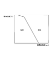
- FIG. 1 is a diagram illustrating a schematic configuration of an exhaust gas purification apparatus for an internal combustion engine according to a first embodiment. It is the figure which showed the relationship between the temperature of a catalyst, and the purification
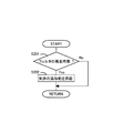
- 3 is a flowchart illustrating a control flow according to the first embodiment.
- FIG. 3 is another diagram showing a schematic configuration of the exhaust gas purification apparatus for an internal combustion engine according to the first embodiment.
- FIG. 5 is a diagram illustrating a schematic configuration of an exhaust gas purification apparatus for an internal combustion engine according to a second embodiment.
- FIG. 6 is another diagram illustrating a schematic configuration of an exhaust gas purification apparatus for an internal combustion engine according to a second embodiment. It is the figure which looked at the dispersion plate from the upstream of the exhaust passage.
- 10 is a flowchart illustrating a control flow according to a third embodiment.
- FIG. 1 is a diagram showing a schematic configuration of an exhaust gas purification apparatus for an internal combustion engine according to the present embodiment.
- the internal combustion engine 1 shown in FIG. 1 is a water-cooled four-cycle diesel engine having four cylinders.
- the following embodiments can be similarly applied even to a gasoline engine.
- the exhaust passage 2 is connected to the internal combustion engine 1.
- a sensor 4 a liquid injection valve 5, a gas injection valve 6, and a catalyst 3 are provided in the exhaust passage 2 in order from the upstream side in the exhaust flow direction.
- the liquid injection valve 5 may be provided in the downstream of the gas injection valve 6, and the liquid injection valve 5 and the gas injection valve 6 may be provided in the same position.
- the senor 4 detects the state of the exhaust, for example, detects the concentration of a specific component in the exhaust.
- the sensor 4 include an air-fuel ratio sensor, an oxygen concentration sensor, an HC sensor, and a NOx sensor. Further, for example, a temperature sensor that detects the temperature of exhaust gas may be used.
- the liquid injection valve 5 injects an additive such as a liquid reducing agent or oxidizing agent.
- the gas injection valve 6 injects an additive such as a gaseous reducing agent or oxidizing agent.
- the additive injected from the liquid injection valve 5 and the gas injection valve 6 may be the same type or different types.
- an ammonia-derived compound can be used as the additive. Examples of the ammonia-derived compound include urea water, urea, ammonia, burette, cyanuric acid, isocyanic acid, and an amine compound.
- fuel (HC) can also be used as an additive. What is used as the additive depends on the type of the catalyst 3. The additive reacts with the catalyst 3.
- the catalyst 3 examples include an NOx storage reduction catalyst, a selective reduction NOx catalyst, an oxidation catalyst, or a three-way catalyst. Moreover, you may provide the particulate filter which carries these catalysts, or equips them upstream, and collects PM.
- a liquid tank 51 for storing a liquid additive is connected to the liquid injection valve 5.
- the liquid tank 51 has a built-in pump for discharging the additive, and the pump supplies the liquid additive to the liquid injection valve 5.
- a liquid additive may be stored in the additive supply passage.
- the gas injection valve 6 is connected to a gas tank 61 that stores or stores a gaseous additive.
- the gas tank 61 may be stored in a state where the additive is occluded in a catalyst or the like. Further, a gaseous additive may be stored in the additive supply passage.
- the gas tank 61 has a built-in pump for discharging the additive, and the pump supplies the gaseous additive to the gas injection valve 6.
- the liquid injection valve 5 and the liquid tank 51 correspond to the liquid supply device in the present invention.
- the gas injection valve 6 and the gas tank 61 correspond to the gas supply device in the present invention.
- an intake passage 8 is connected to the internal combustion engine 1.
- An air flow meter 9 that outputs a signal corresponding to the amount of intake air flowing through the intake passage 8 is attached in the middle of the intake passage 8. The air flow meter 9 measures the intake air amount of the internal combustion engine 1.
- the internal combustion engine 1 configured as described above is provided with an ECU 10 that is an electronic control unit for controlling the internal combustion engine 1.
- the ECU 10 controls the operation state of the internal combustion engine 1 according to the operation conditions of the internal combustion engine 1 and the request of the driver.
- the ECU 10 outputs an electric signal corresponding to the amount of depression of the accelerator pedal 11 by the driver to detect the engine load, and the crank position sensor 13 that detects the engine speed.
- the liquid injection valve 5 and the gas injection valve 6 are connected to the ECU 10 via electric wiring, and the liquid injection valve 5 and the gas injection valve 6 are controlled by the ECU 10.
- the sensor 4 the air flow meter 9, the accelerator opening sensor 12, or the crank position sensor 13 corresponds to the detection device in the present invention.
- the senor 4 is a NOx sensor
- the liquid injection valve 5 is added with urea water
- the gas injection valve 6 is added with ammonia gas
- the catalyst 3 is described as a selective reduction type NOx catalyst.
- the urea water added from the liquid injection valve 5 is hydrolyzed by the heat of the exhaust gas to become ammonia (NH 3 ), and part or all of the urea water is supplied to the catalyst 3.
- This ammonia selectively reduces NOx.
- ammonia is supplied to the catalyst 3 or adsorbed in advance, and the NOx is reduced when NOx passes through the catalyst 3.
- an additive is intermittently added.
- the NOx concentration is detected by the sensor 4, and the NOx amount is calculated from the NOx concentration and the intake air amount. Since the amount of ammonia adsorbed on the catalyst 3 decreases according to the amount of NOx, the additive is supplied when the amount of ammonia adsorbed on the catalyst 3 falls below a specified amount. Note that the additive supply interval may be constant, and the amount of additive may be determined according to the NOx concentration obtained by the sensor 4.
- the liquid additive (urea water) takes longer to hydrolyze when the temperature of the exhaust gas is lower or the space velocity (SV) is lower than the gas additive (ammonia gas), Since the additive adheres to the catalyst 3 or the wall surface of the exhaust passage 2, the purification rate is low or the reaction rate is low.
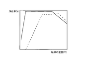
- FIG. 2 is a graph showing the relationship between the temperature of the catalyst 3 and the exhaust gas purification rate.
- the purification rate indicates the ratio of the amount of NOx purified by the catalyst 3 to the amount of NOx flowing into the catalyst 3.
- the solid line indicates the case of a gas additive
- the broken line indicates the case of a liquid additive.
- the gas additive exhibits a high purification rate from the time when the temperature of the catalyst 3 is low, whereas the liquid additive is purified unless the temperature of the catalyst 3 is high to some extent.
- the rate does not increase. That is, when the temperature of the catalyst 3 is low, even if urea water is supplied, the conversion rate to ammonia is low, so the purification rate is low. For this reason, when the temperature of the catalyst 3 is low, the purification rate is higher when the gaseous additive is supplied than when the liquid additive is supplied. On the other hand, when the temperature of the catalyst 3 is high, the purification rate is higher when the liquid additive is supplied than when the gaseous additive is supplied.
- FIG. 3 is a time chart showing the transition of the purification rate.
- a solid line indicates a case where the SV is relatively low, and a broken line indicates a case where the SV is relatively high. As can be seen from FIG. 3, it takes more time for the purification rate to be higher in the case of the low SV than in the case of the high SV.
- the gas additive (ammonia gas) has a characteristic that the purification rate is low during the transient operation of the internal combustion engine 1 as compared with the liquid additive (urea water). This is because the gaseous additive easily passes through the catalyst 3 when the amount of exhaust gas passing through the catalyst 3 increases.
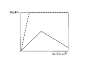
- FIG. 4 is a diagram showing the relationship between the rate of change of the intake air amount and the purification rate during the transient operation of the internal combustion engine 1.
- the solid line shows the case of a gas additive, and the broken line shows the case of a liquid additive.
- the intake air amount is the amount of air taken into the internal combustion engine 1 per unit time.
- the change rate (Ga / ⁇ ) of the intake air amount is the change amount per unit time of the intake air amount. Note that since the amount of intake air has a correlation with the amount of exhaust, the amount of intake air is used instead of the amount of exhaust passing through the catalyst 3. The greater the rate of change of the intake air amount, the greater the degree of acceleration.
- the liquid additive can maintain a high purification rate even when the rate of change of the intake air amount increases.
- the purification rate of the gaseous additive once increases as the rate of change of the intake air amount increases.
- the rate of change of the intake air amount exceeds a certain value, the purification rate starts to decrease.
- the higher the rate of change of the intake air amount the easier the gaseous additive slips through the catalyst 3.
- the volume of the supplied additive becomes too large, and it becomes difficult to supply the additive.
- the additive is supplied in consideration of these.
- the additive can be added simultaneously from the liquid injection valve 5 and the gas injection valve 6 or at different times.
- an additive can also be added only from either one.
- the amounts of the liquid additive and the gas additive are adjusted according to the operating state of the internal combustion engine 1. This may be achieved by adjusting the ratio of the liquid additive and the gas additive in accordance with the operating state of the internal combustion engine 1. These may be adjusted according to the state of the catalyst 3.
- the liquid additive and the gas additive are different in the amount (may be a ratio) of slipping through the catalyst 3, the additive having the smaller slipping amount is supplied. Thereby, since it can suppress that an additive slips through the catalyst 3, the consumption of an additive can be reduced. Further, the NOx purification rate can be increased. For example, when the purification rate differs between the liquid additive and the gas additive depending on the operating state of the internal combustion engine 1, the ratio of the higher purification rate may be increased. As the operating state of the internal combustion engine 1, for example, the engine speed and the engine load can be used.
- the liquid additive supply ratio is increased and the gas additive supply ratio is decreased during transient operation such as acceleration.
- the rate of change of the intake air amount is equal to or higher than the threshold value, only the liquid additive may be supplied.
- This threshold value may be a boundary as to whether or not the NOx purification rate when the gaseous additive is supplied becomes an allowable value.
- the accelerator opening and its duration instead of the rate of change of the intake air amount, the accelerator opening and its duration, the increase in the amount of fuel supplied into the combustion chamber of the internal combustion engine 1, or the increase in the required torque can be used.
- the ratio of the liquid additive is increased or only the liquid additive is supplied.
- the supply amount of the additive per unit time may be adjusted during steady operation and transient operation.
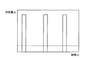
- FIG. 5 is a time chart showing the transition of the supply amount of the additive.
- the solid line shows the case where only the liquid additive is supplied during the transient operation, and the broken line shows the case where the liquid and gas additive is supplied during the steady operation.
- the supply amount per time when the additive is supplied is reduced, and the supply interval is shortened. In this case, a constant amount of additive may be always supplied.
- the supply amount per time when the additive is supplied is increased and the supply interval is lengthened. This may be that the supply amount per unit time when the additive is supplied is increased and the supply interval is lengthened.
- the supply amount per unit time may be increased by increasing the injection pressure of the liquid additive. As described above, if the supply amount per time when the additive is supplied is increased, or if the supply amount per unit time is increased, the liquid additive is less likely to be vaporized. The amount of increases. Thereby, since it can suppress that an additive slips through the catalyst 3, the fall of the purification rate of NOx can be suppressed.
- FIG. 6 is a graph showing the relationship among the engine speed, the engine load, and the additive supply mode.
- the engine load may be the accelerator opening, the average effective pressure, the shaft torque, or the amount of fuel injected into the combustion chamber of the internal combustion engine 1.
- the solid line shows the boundary between the region for supplying the gaseous additive and the region for supplying the liquid additive.
- the broken line has shown the range where the amount of exhaust (it is good also as the pressure of exhaust) is equal.
- the amount of exhaust increases.
- a liquid additive is supplied on the side where the engine speed is higher than the solid line. Note that an optimum value of the boundary between the liquid and the gas shown in FIG. This boundary may be determined so that the NOx purification rate when a liquid additive is supplied is equal to or greater than an allowable value, for example.
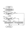
- FIG. 7 is a flowchart showing a control flow according to the present embodiment. This routine is executed by the ECU 10 every predetermined time.
- step S101 the supply amount of the additive is calculated.
- the NOx concentration is detected by the sensor 4, and the NOx amount in the exhaust gas is calculated from the NOx concentration and the intake air amount. Since the amount of ammonia adsorbed on the catalyst 3 decreases in accordance with the amount of NOx, an amount of additive that compensates for this decrease is supplied.
- the supply amount of the additive may be a specified amount, and the supply interval may be adjusted instead.
- step S102 it is determined whether or not a condition for supplying the additive is satisfied. For example, NOx cannot be purified unless the temperature of the catalyst 3 reaches the activation temperature, and therefore it is determined that the condition for supplying the additive is not satisfied. Further, for example, it is determined that the condition for supplying the additive is satisfied when the amount of ammonia adsorbed on the catalyst 3 becomes a specified amount or less. If an affirmative determination is made in step S102, the process proceeds to step S103. If a negative determination is made, the additive cannot be supplied, and thus this routine is terminated.
- step S103 it is determined whether or not only the liquid additive is supplied.
- the internal combustion engine 1 is accelerated, it is determined that only the liquid additive is supplied.
- the internal combustion engine 1 is in a steady state, it is determined by measuring the engine speed and the engine load and substituting the measured values into the map shown in FIG.
- the map shown in FIG. 6 is obtained in advance by experiments or the like and stored in the ECU 10.
- step S103 When an affirmative determination is made in step S103, the process proceeds to step S104, and the liquid additive is supplied from the liquid injection valve 5.
- step S105 When a negative determination is made in step S103, the process proceeds to step S105, and a gaseous additive is supplied from the gas injection valve 6.
- the ECU 10 that processes step S103 corresponds to the adjusting device according to the present invention.
- the boundary is provided to supply either the liquid or gas additive, but instead, a region for supplying both the liquid and gas additive is provided, In the region, the ratio of the supply amount of the liquid additive may be increased and the ratio of the supply amount of the gas additive may be decreased as the engine speed or the engine load increases.
- a liquid additive may be supplied when the temperature of the exhaust gas is equal to or higher than a threshold
- a gas additive may be supplied when the temperature of the exhaust gas is lower than the threshold.
- the threshold value is a temperature at which the NOx purification rate when a liquid additive is supplied is equal to or higher than an allowable value.
- the supply ratio of the liquid additive and the gas additive may be determined according to the temperature of the exhaust.
- FIG. 8 is a graph showing the relationship among the engine speed, the exhaust temperature, and the additive supply mode.
- FIG. 8 shows the case of steady operation.
- the solid line shows the boundary between the region for supplying the gaseous additive and the region for supplying the liquid additive.
- a gaseous additive is supplied on the side where the engine speed is lower than the solid line.
- a liquid additive is supplied on the side where the engine speed is higher than the solid line. Note that the optimum value of the boundary between the liquid and the gas shown in FIG. This boundary may be determined so that the NOx purification rate when a liquid additive is supplied is equal to or greater than an allowable value, for example.
- a boundary is provided to supply either one of the liquid and gas additives, but instead, a region for supplying both the liquid and gas additives is provided.
- the ratio of the supply amount of the liquid additive may be increased as the engine speed or the exhaust gas temperature increases.
- the exhaust temperature may be measured by the sensor 4 or may be estimated from the operating state of the internal combustion engine 1. Further, the temperature of the catalyst 3 may be used instead of the exhaust temperature.
- FIG. 9 is another diagram showing a schematic configuration of the exhaust gas purification apparatus for an internal combustion engine according to the present embodiment. Differences from FIG. 1 will be described.
- a dispersion device 20 for dispersing the additive in a wider range is provided downstream of the liquid injection valve 5 and upstream of the gas injection valve 6.
- the dispersion device 20 may be provided on the upstream side of the liquid injection valve 5. Further, the dispersion device 20 may be provided on the downstream side of the gas injection valve 6. Furthermore, the positions of the liquid injection valve 5 and the gas injection valve 6 may be reversed.
- the dispersing device 20 may be any device that increases the disturbance of the exhaust or turns the exhaust.
- a plate having a plurality of holes may be installed perpendicular to the exhaust flow.
- the additive is dispersed in a wider range in the exhaust gas, so that the additive can be supplied uniformly to the catalyst 3. Further, the vaporization of the liquid additive can be promoted.
- the amount of liquid additive and the amount of gaseous additive can be adjusted based on the operating state of the internal combustion engine 1 and the like. That is, the amount of liquid additive and the amount of gaseous additive can be adjusted according to predetermined rules. Thereby, the purification rate of the exhaust gas in the catalyst 3 can be increased, or the supply amount of the additive can be decreased. Further, in a state in which the gaseous additive easily slips through the catalyst 3 as in transient operation, the liquid additive is supplied, so that the additive can be prevented from slipping through the catalyst 3. Further, since the gas tank 61 is provided, it is not necessary to heat and vaporize the liquid or solid additive with a heater or the like, so that energy consumption can be reduced. Thus, the additive can be efficiently supplied to the catalyst 3.
- FIG. 10 is a diagram showing a schematic configuration of an exhaust gas purification apparatus for an internal combustion engine according to the present embodiment. Differences from FIG. 1 will be described.
- the liquid injection valve 5 and the gas injection valve 6 are provided to face each other.
- the liquid additive injected from the liquid injection valve 5 and the gas additive injected from the gas injection valve 6 collide with each other in the exhaust passage 2.
- both additives are dispersed in a wider range in the exhaust gas, so that the additives can be supplied uniformly to the catalyst 3.
- both additives should just collide, the liquid injection valve 5 and the gas injection valve 6 may have shifted
- FIG. 11 is another diagram showing a schematic configuration of the exhaust gas purification apparatus for an internal combustion engine according to the present embodiment. Differences from FIG. 10 will be described.
- a dispersion plate 21 is provided in the exhaust passage 2 between the liquid injection valve 5 and the gas injection valve 6 to cause disturbance in the exhaust flow.
- the dispersion plate 21 disperses the additive over a wide range in the exhaust gas.
- FIG. 12 is a view of the dispersion plate 21 as viewed from the upstream side of the exhaust passage 2.
- the dispersion plate 21 is a substantially rectangular metal plate having a surface inclined with respect to the flow direction of the exhaust gas, that is, the central axis direction of the exhaust passage 2.
- the area of the dispersion plate 21 is smaller than the passage area of the exhaust passage 2.
- the length of the dispersion plate 21 is longer than the diameter of the exhaust passage 2, and the width is shorter than the diameter of the exhaust passage 2.
- the length direction of the dispersion plate 21 is inclined with respect to the exhaust flow direction, and the width direction of the dispersion plate 21 is orthogonal to the exhaust flow direction.
- the center of the dispersion plate 21 is located on the central axis of the exhaust passage 2, and the upstream end and the downstream end of the dispersion plate 21 are welded to the wall surface of the exhaust passage 2, respectively.
- the width of the dispersion plate 21 is shorter than the diameter of the exhaust passage 2, the exhaust can flow between the dispersion plate 21 and the wall surface of the exhaust passage 2.
- the liquid injection valve 5 is attached to the side of the surface facing the upstream side of the dispersion plate 21.
- the gas injection valve 6 is attached to the side of the surface facing the downstream side of the dispersion plate 21.
- the positions of the liquid injection valve 5 and the gas injection valve 6 may be reversed.
- the dispersion plate 21 may be a flat plate, but may be a corrugated plate or the like. A plurality of holes may be formed in the dispersion plate 21 or a catalyst may be supported.
- the exhaust gas flows through the side of the dispersion plate 21.
- the exhaust before passing through the side of the dispersion plate 21 flows around the liquid injection valve 5, and the exhaust after passing through the side of the dispersion plate 21 flows around the gas injection valve 6.
- the dispersion plate 21 in the exhaust flow, the exhaust flow is disturbed, so that the additive is dispersed in a wide range.
- the additive may be dispersed by colliding with the dispersion plate 21.
- the dispersion plate 21 corresponds to the “plate on which the additive collides” in the present invention.
- the additives can be further dispersed by collision of both the additives. Further, since the additive added from the liquid injection valve 5 and the additive added from the gas injection valve 6 are dispersed in a wider range in the exhaust gas by the dispersion plate 21, the additive is uniformly distributed in the catalyst 3. Can be supplied to. Furthermore, the liquid injection valve 5, the gas injection valve 6, and the dispersion plate 21 can be installed in a narrow range of the exhaust passage 2.
- the catalyst 3 is supported on a filter. Since other devices are the same as those in the first embodiment, description thereof is omitted.
- the additive is added only from the gas injection valve 6 when the filter is regenerated. By reacting the additive with the catalyst 3, the temperature of the filter is raised. Then, the PM collected in the filter is oxidized by oxygen contained in the exhaust gas. If a liquid additive is added during the regeneration of the filter, the liquid additive may adhere to the wall surface of the exhaust passage 2 or the catalyst 3 and solidify. For this reason, in this embodiment, only the gaseous additive is added when the filter is regenerated. When the filter is regenerated, the ratio of the gaseous additive may be increased and the ratio of the liquid additive may be decreased compared to other times.
- FIG. 13 is a flowchart showing a control flow according to the present embodiment. This routine is executed by the ECU 10 every predetermined time.
- step S201 it is determined whether it is time to regenerate the filter.
- the regeneration of the filter is performed, for example, when the PM emission amount estimated from the operating state of the internal combustion engine 1 is integrated and this integrated value becomes a threshold value. If an affirmative determination is made in step S201, the process proceeds to step S202. On the other hand, if a negative determination is made, this routine is terminated, and an additive is added according to the operating state at that time.
- step S202 an additive is added only from the gas injection valve 6 to regenerate the filter.
- the amount of additive added at this time may be feedback controlled so that, for example, the temperature of the filter becomes an optimum temperature for regeneration of the filter.
- the filter when removing the additive adsorbed on the catalyst 3, only the gaseous additive may be added. In this case, the filter may not be provided.
- the catalyst 3 is a selective reduction type NOx catalyst
- ammonia is adsorbed on the catalyst 3 in advance. Then, when the amount of ammonia adsorbed on the catalyst 3 becomes less than the specified amount, an additive is supplied to keep the amount of ammonia adsorbed on the catalyst 3 at the specified amount.
- the amount of ammonia adsorbed on the catalyst 3 is estimated by the ECU 10.
- it is difficult to purify NOx when a part of the ammonia adsorbed on the catalyst 3 is solidified, it is difficult to purify NOx. In this case, even if the amount of ammonia adsorbed on the catalyst 3 is estimated to be equal to or greater than the specified amount, the NOx purification rate is lowered.
- step S201 it is determined whether or not it is time to increase the temperature of the catalyst 3. For example, when a predetermined time has elapsed, it is determined that it is time to increase the temperature of the catalyst 3.
- the ratio of the gaseous additive may be increased and the ratio of the liquid additive may be decreased compared to other cases.
- the filter when the filter is regenerated or when the additive adsorbed on the catalyst 3 is removed, only the gas additive is added or the ratio of the gas additive is increased. Therefore, the liquid additive can be prevented from adhering to the catalyst 3 and solidifying. Thereby, since the supply amount of the additive can be reduced, the additive can be efficiently supplied to the catalyst 3.
Landscapes
- Engineering & Computer Science (AREA)
- Chemical & Material Sciences (AREA)
- Chemical Kinetics & Catalysis (AREA)
- Combustion & Propulsion (AREA)
- Mechanical Engineering (AREA)
- General Engineering & Computer Science (AREA)
- Health & Medical Sciences (AREA)
- Toxicology (AREA)
- Exhaust Gas After Treatment (AREA)
- Exhaust Gas Treatment By Means Of Catalyst (AREA)
Abstract
Description
液体の添加剤を蓄えておき内燃機関の排気通路内に液体の添加剤を供給する液体供給装置と、
気体の添加剤を蓄えておき前記排気通路内に気体の添加剤を供給する気体供給装置と、
前記液体供給装置及び前記気体供給装置から添加剤が供給される箇所よりも下流側の排気通路に設けられ添加剤が反応する触媒と、
前記液体供給装置から添加される液体の添加剤の量と、前記気体供給装置により添加される気体の添加剤の量と、を予め定められた規則に従って調節する調節装置と、
を備える。
前記調節装置は、前記液体供給装置から添加される液体の添加剤の量と、前記気体供給装置により添加される気体の添加剤の量と、を前記検出装置により検出される物理量に基づいて調節することができる。
前記調節装置は、内燃機関の加速時には、定常時よりも、前記液体供給装置から添加される液体の添加剤の割合を高くし、前記気体供給装置により添加される気体の添加剤の割合を低くすることができる。
前記調節装置は、前記フィルタの再生を行なうときには、前記液体供給装置から添加される液体の添加剤の割合を低くし、前記気体供給装置により添加される気体の添加剤の割合を高くすることができる。
2 排気通路
3 触媒
4 センサ
5 液体噴射弁
6 気体噴射弁
8 吸気通路
9 エアフローメータ
10 ECU
11 アクセルペダル
12 アクセル開度センサ
13 クランクポジションセンサ
20 分散装置
21 分散板
51 液体タンク
61 気体タンク
Claims (10)
- 液体の添加剤を蓄えておき内燃機関の排気通路内に液体の添加剤を供給する液体供給装置と、
気体の添加剤を蓄えておき前記排気通路内に気体の添加剤を供給する気体供給装置と、
前記液体供給装置及び前記気体供給装置から添加剤が供給される箇所よりも下流側の排気通路に設けられ添加剤が反応する触媒と、
前記液体供給装置から添加される液体の添加剤の量と、前記気体供給装置により添加される気体の添加剤の量と、を予め定められた規則に従って調節する調節装置と、
を備えることを特徴とする内燃機関の排気浄化装置。 - 前記触媒をすり抜ける気体の添加剤の量と相関関係にある物理量を検出する検出装置を備え、
前記調節装置は、前記液体供給装置から添加される液体の添加剤の量と、前記気体供給装置により添加される気体の添加剤の量と、を前記検出装置により検出される物理量に基づいて調節することを特徴とする請求項1に記載の内燃機関の排気浄化装置。 - 前記調節装置は、前記物理量によって示される前記触媒をすり抜ける気体の添加剤の量が多くなる領域ほど、前記液体供給装置から添加される液体の添加剤の割合を高くし、前記気体供給装置により添加される気体の添加剤の割合を低くすることを特徴とする請求項2に記載の内燃機関の排気浄化装置。
- 前記検出装置は、内燃機関の加速を検出し、
前記調節装置は、内燃機関の加速時には、定常時よりも、前記液体供給装置から添加される液体の添加剤の割合を高くし、前記気体供給装置により添加される気体の添加剤の割合を低くすることを特徴とする請求項2または3に記載の内燃機関の排気浄化装置。 - 前記内燃機関の加速時には、定常時よりも、添加剤を添加するときの1回当たりの量を多くし、且つ、添加する間隔を長くすることを特徴とする請求項4に記載の内燃機関の排気浄化装置。
- 前記触媒は、排気中の粒子状物質を捕集するフィルタよりも上流側に設けられるか、または該フィルタに担持されており、
前記調節装置は、前記フィルタの再生を行なうときには、前記液体供給装置から添加される液体の添加剤の割合を低くし、前記気体供給装置により添加される気体の添加剤の割合を高くすることを特徴とする請求項1に記載の内燃機関の排気浄化装置。 - 前記調節装置は、前記触媒の温度を、該触媒に吸着している添加剤が除去される温度まで上昇させるために添加剤を添加するときには、前記液体供給装置から添加される液体の添加剤の割合を低くし、前記気体供給装置により添加される気体の添加剤の割合を高くすることを特徴とする請求項1に記載の内燃機関の排気浄化装置。
- 前記気体供給装置は、気体の添加剤を排気中に噴射する気体噴射弁を備えて構成され、前記液体供給装置は、液体の添加剤を排気中に噴射する液体噴射弁を備えて構成され、前記気体噴射弁と前記液体噴射弁とを対向して設けることを特徴とする請求項1から7の何れか1項に記載の内燃機関の排気浄化装置。
- 前記気体噴射弁と前記液体噴射弁との間に、添加剤を衝突させる板を設けることを特徴とする請求項8に記載の内燃機関の排気浄化装置。
- 前記気体噴射弁からはアンモニアガスを噴射し、前記液体噴射弁からはHCを噴射することを特徴とする請求項8または9に記載の内燃機関の排気浄化装置。
Priority Applications (5)
| Application Number | Priority Date | Filing Date | Title |
|---|---|---|---|
| JP2010550968A JP5141779B2 (ja) | 2010-03-05 | 2010-03-05 | 内燃機関の排気浄化装置 |
| CN201080002018.5A CN102859135B (zh) | 2010-03-05 | 2010-03-05 | 内燃机的排气净化装置 |
| EP10792805.3A EP2543837B1 (en) | 2010-03-05 | 2010-03-05 | Exhaust gas purification apparatus of an internal combustion engine |
| PCT/JP2010/053631 WO2011108110A1 (ja) | 2010-03-05 | 2010-03-05 | 内燃機関の排気浄化装置 |
| US13/001,846 US8677736B2 (en) | 2010-03-05 | 2010-03-05 | Exhaust gas purification apparatus of an internal combustion engine |
Applications Claiming Priority (1)
| Application Number | Priority Date | Filing Date | Title |
|---|---|---|---|
| PCT/JP2010/053631 WO2011108110A1 (ja) | 2010-03-05 | 2010-03-05 | 内燃機関の排気浄化装置 |
Publications (1)
| Publication Number | Publication Date |
|---|---|
| WO2011108110A1 true WO2011108110A1 (ja) | 2011-09-09 |
Family
ID=44541794
Family Applications (1)
| Application Number | Title | Priority Date | Filing Date |
|---|---|---|---|
| PCT/JP2010/053631 Ceased WO2011108110A1 (ja) | 2010-03-05 | 2010-03-05 | 内燃機関の排気浄化装置 |
Country Status (5)
| Country | Link |
|---|---|
| US (1) | US8677736B2 (ja) |
| EP (1) | EP2543837B1 (ja) |
| JP (1) | JP5141779B2 (ja) |
| CN (1) | CN102859135B (ja) |
| WO (1) | WO2011108110A1 (ja) |
Cited By (6)
| Publication number | Priority date | Publication date | Assignee | Title |
|---|---|---|---|---|
| JP2013122225A (ja) * | 2011-12-12 | 2013-06-20 | Mitsubishi Motors Corp | 内燃機関の排気浄化装置 |
| JP2013130109A (ja) * | 2011-12-21 | 2013-07-04 | Mitsubishi Motors Corp | 内燃機関の排ガス浄化装置及び浄化方法 |
| JP2013130073A (ja) * | 2011-12-20 | 2013-07-04 | Mitsubishi Motors Corp | 内燃機関の排ガス浄化装置及び浄化方法 |
| DE102015223475A1 (de) | 2014-11-27 | 2016-06-02 | Toyota Jidosha Kabushiki Kaisha | Abgasreinigungsvorrichtung einer Brennkraftmaschine |
| JP2016517922A (ja) * | 2013-04-17 | 2016-06-20 | ボルボ トラック コーポレイション | 排気管路内に反応物質を噴射するためのシステム |
| JP2020133451A (ja) * | 2019-02-15 | 2020-08-31 | トヨタ自動車株式会社 | 内燃機関の排気浄化装置 |
Families Citing this family (12)
| Publication number | Priority date | Publication date | Assignee | Title |
|---|---|---|---|---|
| US10683787B2 (en) | 2018-11-08 | 2020-06-16 | Faurecia Emissions Control Technologies, Usa, Llc | Automotive exhaust aftertreatment system having onboard ammonia reactor with hybrid heating |
| US10767529B2 (en) | 2018-11-08 | 2020-09-08 | Faurecia Emissions Control Technologies, Usa, Llc | Automotive exhaust aftertreatment system having onboard ammonia reactor with heated doser |
| US10876454B2 (en) | 2018-11-08 | 2020-12-29 | Faurecia Emissions Control Technologies, Usa, Llc | Automotive exhaust aftertreatment system with multi-reductant injection and doser controls |
| US11193413B2 (en) | 2019-12-12 | 2021-12-07 | Faurecia Emissions Control Technologies, Usa, Llc | Exhaust aftertreatment system with virtual temperature determination and control |
| EP3882440A1 (en) * | 2020-03-19 | 2021-09-22 | Winterthur Gas & Diesel Ltd. | Device and method for providing a reducing agent |
| US11319853B2 (en) | 2020-03-31 | 2022-05-03 | Faurecia Emissions Control Technologies, Usa, Llc | Automotive exhaust aftertreatment system with doser |
| US11022014B1 (en) | 2020-04-28 | 2021-06-01 | Faurecia Emissions Control Technologies, Usa, Llc | Exhaust aftertreatment system with heated flash-boiling doser |
| US11511239B2 (en) | 2020-04-29 | 2022-11-29 | Faurecia Emissions Control Technologies, Usa, Llc | Heated flash-boiling doser with integrated helix |
| US11092054B1 (en) | 2020-04-29 | 2021-08-17 | Faurecia Emissions Control Technologies, Usa, Llc | Flash-boiling doser with thermal transfer helix |
| US11384667B2 (en) | 2020-05-29 | 2022-07-12 | Faurecia Emissions Control Technologies, Usa, Llc | Exhaust aftertreatment system with heated dosing control |
| US11225894B1 (en) | 2020-06-30 | 2022-01-18 | Faurecia Emissions Control Technologies, Usa, Llc | Exhaust aftertreatment system with thermally controlled reagent doser |
| CN113685249A (zh) * | 2021-08-19 | 2021-11-23 | 潍柴动力股份有限公司 | 后处理喷射系统、车辆及控制方法 |
Citations (4)
| Publication number | Priority date | Publication date | Assignee | Title |
|---|---|---|---|---|
| JP2001113134A (ja) * | 1999-10-20 | 2001-04-24 | Tokyo Gas Co Ltd | NOx含有排ガスの浄化方法 |
| JP2004044499A (ja) * | 2002-07-12 | 2004-02-12 | Toyota Central Res & Dev Lab Inc | 内燃機関の排気浄化装置 |
| JP2008075543A (ja) * | 2006-09-21 | 2008-04-03 | Hino Motors Ltd | エンジンの排ガス浄化装置 |
| JP2008157188A (ja) * | 2006-12-26 | 2008-07-10 | Mitsubishi Fuso Truck & Bus Corp | 排気浄化装置 |
Family Cites Families (12)
| Publication number | Priority date | Publication date | Assignee | Title |
|---|---|---|---|---|
| WO1999056858A2 (de) * | 1998-04-30 | 1999-11-11 | Siemens Aktiengesellschaft | Verfahren und vorrichtung zur katalytischen stickoxidminderung |
| US6852292B2 (en) * | 2002-04-24 | 2005-02-08 | Kleenair Systems, Inc. | Ammonia storage and injection in NOx control |
| JP4266104B2 (ja) * | 2002-07-29 | 2009-05-20 | 東芝キヤリア株式会社 | 横形ロータリ式圧縮機 |
| DE10251472A1 (de) * | 2002-11-06 | 2004-05-19 | Robert Bosch Gmbh | Verfahren zur Nachbehandlung von Abgasen und Anordnung hierzu |
| JP4262522B2 (ja) * | 2003-05-28 | 2009-05-13 | 株式会社日立ハイテクノロジーズ | エンジン用排気ガス処理装置および排気ガス処理方法 |
| DE202005001257U1 (de) * | 2004-09-17 | 2005-04-07 | Arvinmeritor Emissions Tech | Abgasanlage eines Kfzs mit Dieselmotor |
| US7485272B2 (en) * | 2005-11-30 | 2009-02-03 | Caterpillar Inc. | Multi-stage system for selective catalytic reduction |
| US20070277505A1 (en) * | 2006-05-30 | 2007-12-06 | Ford Global Technologies, Llc | Venting of on-board vehicle emissions treatment system |
| US8015801B2 (en) * | 2006-09-18 | 2011-09-13 | Ford Global Technologies, Llc | Management of a plurality of reductants for selective catalytic reduction |
| US7954311B2 (en) * | 2007-03-15 | 2011-06-07 | Ford Global Technologies, Llc | Ammonia vapor management system and method |
| JP5222616B2 (ja) | 2008-04-23 | 2013-06-26 | 日野自動車株式会社 | 排気浄化装置 |
| FR2953737B1 (fr) * | 2009-12-11 | 2013-03-15 | Inst Francais Du Petrole | Procede de traitement de polluants contenus dans des gaz d'echappement, notamment d'un moteur a combustion interne, et installation utilisant un tel procede |
-
2010
- 2010-03-05 EP EP10792805.3A patent/EP2543837B1/en not_active Not-in-force
- 2010-03-05 WO PCT/JP2010/053631 patent/WO2011108110A1/ja not_active Ceased
- 2010-03-05 JP JP2010550968A patent/JP5141779B2/ja not_active Expired - Fee Related
- 2010-03-05 US US13/001,846 patent/US8677736B2/en not_active Expired - Fee Related
- 2010-03-05 CN CN201080002018.5A patent/CN102859135B/zh not_active Expired - Fee Related
Patent Citations (4)
| Publication number | Priority date | Publication date | Assignee | Title |
|---|---|---|---|---|
| JP2001113134A (ja) * | 1999-10-20 | 2001-04-24 | Tokyo Gas Co Ltd | NOx含有排ガスの浄化方法 |
| JP2004044499A (ja) * | 2002-07-12 | 2004-02-12 | Toyota Central Res & Dev Lab Inc | 内燃機関の排気浄化装置 |
| JP2008075543A (ja) * | 2006-09-21 | 2008-04-03 | Hino Motors Ltd | エンジンの排ガス浄化装置 |
| JP2008157188A (ja) * | 2006-12-26 | 2008-07-10 | Mitsubishi Fuso Truck & Bus Corp | 排気浄化装置 |
Cited By (8)
| Publication number | Priority date | Publication date | Assignee | Title |
|---|---|---|---|---|
| JP2013122225A (ja) * | 2011-12-12 | 2013-06-20 | Mitsubishi Motors Corp | 内燃機関の排気浄化装置 |
| JP2013130073A (ja) * | 2011-12-20 | 2013-07-04 | Mitsubishi Motors Corp | 内燃機関の排ガス浄化装置及び浄化方法 |
| JP2013130109A (ja) * | 2011-12-21 | 2013-07-04 | Mitsubishi Motors Corp | 内燃機関の排ガス浄化装置及び浄化方法 |
| JP2016517922A (ja) * | 2013-04-17 | 2016-06-20 | ボルボ トラック コーポレイション | 排気管路内に反応物質を噴射するためのシステム |
| DE102015223475A1 (de) | 2014-11-27 | 2016-06-02 | Toyota Jidosha Kabushiki Kaisha | Abgasreinigungsvorrichtung einer Brennkraftmaschine |
| US9598997B2 (en) | 2014-11-27 | 2017-03-21 | Toyota Jidosha Kabushiki Kaisha | Exhaust gas purification apparatus of internal combustion engine |
| JP2020133451A (ja) * | 2019-02-15 | 2020-08-31 | トヨタ自動車株式会社 | 内燃機関の排気浄化装置 |
| JP7056605B2 (ja) | 2019-02-15 | 2022-04-19 | 株式会社豊田自動織機 | 内燃機関の排気浄化装置 |
Also Published As
| Publication number | Publication date |
|---|---|
| US8677736B2 (en) | 2014-03-25 |
| EP2543837A1 (en) | 2013-01-09 |
| EP2543837A4 (en) | 2014-01-01 |
| CN102859135B (zh) | 2014-12-31 |
| US20110219754A1 (en) | 2011-09-15 |
| EP2543837B1 (en) | 2016-11-23 |
| JP5141779B2 (ja) | 2013-02-13 |
| CN102859135A (zh) | 2013-01-02 |
| JPWO2011108110A1 (ja) | 2013-06-20 |
Similar Documents
| Publication | Publication Date | Title |
|---|---|---|
| JP5141779B2 (ja) | 内燃機関の排気浄化装置 | |
| US7842267B2 (en) | Exhaust emission purifying apparatus for engine | |
| JP5653618B2 (ja) | 選択的触媒還元の制御 | |
| CN101637702B (zh) | 选择性催化还原催化剂当前储存量的估算 | |
| USRE48658E1 (en) | Exhaust gas purification apparatus for an internal combustion engine | |
| JP5382129B2 (ja) | 内燃機関の排気浄化装置及び排気浄化方法 | |
| JP2009275666A (ja) | 内燃機関の排気浄化装置 | |
| KR20150005703A (ko) | 배기 후처리 시스템 및 그와 같은 시스템에 관한 방법 | |
| JP5915516B2 (ja) | 内燃機関の排気浄化装置 | |
| WO2014097391A1 (ja) | 内燃機関の排気浄化システム | |
| EP3075975B1 (en) | Exhaust gas purification device for internal combustion engine | |
| EP2570625B1 (en) | Exhaust gas purification system for internal combustion engine | |
| JP4432917B2 (ja) | 内燃機関の排気浄化装置 | |
| CN104619963B (zh) | 用于确定还原剂滑脱的方法 | |
| JP2016079852A (ja) | 内燃機関の排気浄化装置の異常判定システム | |
| WO2014097393A1 (ja) | 内燃機関の排気浄化装置 | |
| US10364727B2 (en) | Exhaust gas purification apparatus for an internal combustion engine | |
| US9464554B2 (en) | Exhaust gas purification system for internal combustion engine | |
| JP4884270B2 (ja) | エンジンの排気浄化装置 | |
| JP2008223670A (ja) | エンジンの排気浄化装置 | |
| JP5553630B2 (ja) | 内燃機関の排気浄化装置 | |
| JP2010159693A (ja) | 内燃機関の排気浄化装置 |
Legal Events
| Date | Code | Title | Description |
|---|---|---|---|
| WWE | Wipo information: entry into national phase |
Ref document number: 201080002018.5 Country of ref document: CN |
|
| WWE | Wipo information: entry into national phase |
Ref document number: 2010550968 Country of ref document: JP |
|
| WWE | Wipo information: entry into national phase |
Ref document number: 13001846 Country of ref document: US |
|
| REEP | Request for entry into the european phase |
Ref document number: 2010792805 Country of ref document: EP |
|
| WWE | Wipo information: entry into national phase |
Ref document number: 2010792805 Country of ref document: EP |
|
| 121 | Ep: the epo has been informed by wipo that ep was designated in this application |
Ref document number: 10792805 Country of ref document: EP Kind code of ref document: A1 |
|
| NENP | Non-entry into the national phase |
Ref country code: DE |