WO2011108133A1 - スタータ - Google Patents
スタータ Download PDFInfo
- Publication number
- WO2011108133A1 WO2011108133A1 PCT/JP2010/064406 JP2010064406W WO2011108133A1 WO 2011108133 A1 WO2011108133 A1 WO 2011108133A1 JP 2010064406 W JP2010064406 W JP 2010064406W WO 2011108133 A1 WO2011108133 A1 WO 2011108133A1
- Authority
- WO
- WIPO (PCT)
- Prior art keywords
- rotational speed
- clutch
- pinion
- engine
- starter
- Prior art date
- Legal status (The legal status is an assumption and is not a legal conclusion. Google has not performed a legal analysis and makes no representation as to the accuracy of the status listed.)
- Ceased
Links
Images


Classifications
-
- H—ELECTRICITY
- H02—GENERATION; CONVERSION OR DISTRIBUTION OF ELECTRIC POWER
- H02K—DYNAMO-ELECTRIC MACHINES
- H02K11/00—Structural association of dynamo-electric machines with electric components or with devices for shielding, monitoring or protection
- H02K11/20—Structural association of dynamo-electric machines with electric components or with devices for shielding, monitoring or protection for measuring, monitoring, testing, protecting or switching
- H02K11/21—Devices for sensing speed or position, or actuated thereby
-
- F—MECHANICAL ENGINEERING; LIGHTING; HEATING; WEAPONS; BLASTING
- F02—COMBUSTION ENGINES; HOT-GAS OR COMBUSTION-PRODUCT ENGINE PLANTS
- F02N—STARTING OF COMBUSTION ENGINES; STARTING AIDS FOR SUCH ENGINES, NOT OTHERWISE PROVIDED FOR
- F02N15/00—Other power-operated starting apparatus; Component parts, details, or accessories, not provided for in, or of interest apart from groups F02N5/00 - F02N13/00
- F02N15/02—Gearing between starting-engines and started engines; Engagement or disengagement thereof
- F02N15/022—Gearing between starting-engines and started engines; Engagement or disengagement thereof the starter comprising an intermediate clutch
- F02N15/023—Gearing between starting-engines and started engines; Engagement or disengagement thereof the starter comprising an intermediate clutch of the overrunning type
-
- F—MECHANICAL ENGINEERING; LIGHTING; HEATING; WEAPONS; BLASTING
- F02—COMBUSTION ENGINES; HOT-GAS OR COMBUSTION-PRODUCT ENGINE PLANTS
- F02N—STARTING OF COMBUSTION ENGINES; STARTING AIDS FOR SUCH ENGINES, NOT OTHERWISE PROVIDED FOR
- F02N15/00—Other power-operated starting apparatus; Component parts, details, or accessories, not provided for in, or of interest apart from groups F02N5/00 - F02N13/00
- F02N15/02—Gearing between starting-engines and started engines; Engagement or disengagement thereof
- F02N15/04—Gearing between starting-engines and started engines; Engagement or disengagement thereof the gearing including disengaging toothed gears
- F02N15/06—Gearing between starting-engines and started engines; Engagement or disengagement thereof the gearing including disengaging toothed gears the toothed gears being moved by axial displacement
- F02N15/067—Gearing between starting-engines and started engines; Engagement or disengagement thereof the gearing including disengaging toothed gears the toothed gears being moved by axial displacement the starter comprising an electro-magnetically actuated lever
-
- F—MECHANICAL ENGINEERING; LIGHTING; HEATING; WEAPONS; BLASTING
- F02—COMBUSTION ENGINES; HOT-GAS OR COMBUSTION-PRODUCT ENGINE PLANTS
- F02N—STARTING OF COMBUSTION ENGINES; STARTING AIDS FOR SUCH ENGINES, NOT OTHERWISE PROVIDED FOR
- F02N2200/00—Parameters used for control of starting apparatus
- F02N2200/04—Parameters used for control of starting apparatus said parameters being related to the starter motor
- F02N2200/041—Starter speed
-
- F—MECHANICAL ENGINEERING; LIGHTING; HEATING; WEAPONS; BLASTING
- F02—COMBUSTION ENGINES; HOT-GAS OR COMBUSTION-PRODUCT ENGINE PLANTS
- F02N—STARTING OF COMBUSTION ENGINES; STARTING AIDS FOR SUCH ENGINES, NOT OTHERWISE PROVIDED FOR
- F02N2200/00—Parameters used for control of starting apparatus
- F02N2200/04—Parameters used for control of starting apparatus said parameters being related to the starter motor
- F02N2200/048—Information about pinion speed, both translational or rotational speed
Definitions
- the present invention relates to a starter for idling stop.
- a pinion that transmits starter power to the engine to crank the engine is pushed out by a solenoid coil so that the pinion is engaged with a ring gear connected to the crankshaft of the engine. Crank the engine with the power of.
- the starter for idling stop when the vehicle is temporarily stopped, the pinion is pushed out and engaged with the ring gear after the engine is stopped.
- the restart cannot be performed until the engine rotation is stopped, and a time delay occurs until the restart is performed.
- Patent Document 1 when a restart request is generated while the engine speed is decreasing, the starter is energized to idle the pinion, and the rotational speeds of the pinion and the ring gear are detected respectively. When each rotation synchronizes, the pinion is pushed out and engaged with the ring gear, and the engine is restarted quickly.
- Patent Document 2 an uneven signal output portion is formed on the outer peripheral surface of the cylindrical outer wall of the clutch outer of the starter one-way clutch, and the rotation speed of the crankshaft is controlled by a signal detection sensor. Detected.
- Patent Document 1 does not describe a specific method for detecting the rotational speed of the pinion. Moreover, the sensor of patent document 2 detects the rotational speed of a crankshaft, and does not detect the rotational speed of a pinion. That is, the conventional technique has a problem that a method for specifically detecting the rotational speed of the pinion mounted on the starter for idling stop is not considered.
- an object of the present invention is to provide an idling stop starter capable of detecting the rotation speed of a pinion.
- This starter has a pinion that transmits the rotational driving force of the starter to the ring gear of the crankshaft of the engine, an armature shaft that pushes the pinion to the ring gear, and the pinion and the ring gear so that the rotational driving force of the engine is not transmitted to the armature.
- a one-way clutch arranged and a rotation speed detection device for detecting the rotation speed of the pinion, the rotation speed detection device comprising: a rotation speed detected portion formed around the one-way clutch; and the rotation speed detected portion. And a rotational speed detection sensor for detecting.
- an idling stop starter capable of detecting the rotational speed of the pinion.
- FIG. 1 is an overall configuration diagram of a system including a starter.
- the front view of the clutch outer which shows the state which removed the clutch cover.
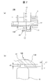
- the principal part sectional drawing which shows the positional relationship of the principal part of a clutch outer and a clutch cover, and a rotational speed detection sensor.
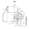
- a ring gear 3 is attached to the crankshaft 2 of the engine 1.
- an armature 6 is rotatably supported inside a starter 5 that generates a rotational driving force for starting the engine 1, and a pinion 7 is attached to one end of the armature shaft 6a.
- the rotational driving force of the starter 5 can be transmitted to the engine 1.
- the starter 5 is provided with a rotation speed detection sensor 8 that detects the rotation speed of the pinion 7.
- the system shown in FIG. 1 includes an engine 1, a ring gear 3 fixed to the crankshaft 2 of the engine 1, a starter 5 having a pinion 7 meshing with the ring gear 3, a battery 4 as a power source of the starter 5, a relay 4a, and a rotation And a speed detection sensor 8.
- it is configured to include a rotation speed detection sensor 9 of the ring gear 3 for detecting the rotation speed of the engine in order to automatically restart after the engine is temporarily stopped, and the control device 20 is operated during the operation of the vehicle.
- the starter 5 is rotated to restart the engine 1.
- a starter 5 is a DC motor, and a built-in armature 6 receives a current from the battery 4 to generate a rotational driving force.
- the rotational driving force generated by the armature 6 is transmitted to the armature shaft 6 a that is the output shaft of the starter 5.
- a one-way clutch 10 is disposed between the armature shaft 6a and the pinion 7 so that the rotational driving force of the engine 1 is not transmitted to the armature 6 after the engine 1 is started.
- a rotation speed detection sensor 8 is disposed at a position facing the outer peripheral portion of the one-way clutch 10 in the radial direction (engine 1 side), and detects a rotation signal of the one-way clutch 10. In this embodiment, a magnetic sensor is used.
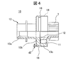
- the one-way clutch 10 includes a pinion 7, a clutch inner 12, a clutch outer 13, and a clutch cover 14 that are arranged coaxially so as to oppose each other in the radial direction via a roller 11.
- the clutch inner 12 is formed integrally with the pinion 7 and is rotationally driven via the armature shaft 6a when the engine 1 is started.
- the one-way clutch 10 is fitted to a spline (not shown) formed on the armature shaft 6a and is movable in the axial direction.
- the one-way clutch 10 prevents the starter 5 from being turned around from the engine 1.
- the clutch outer 13 is separated from the engine rotation by the functions of the clutch inner 12 and the one-way clutch 10 that rotate integrally with the pinion 7.
- the roller 11 connects and separates the clutch inner 12 and the clutch outer 13.
- the outer peripheral surface of the clutch outer 13 is covered with a clutch cover 14 and is externally fitted.
- the clutch outer 13 includes a bearing portion 13a fitted to the armature shaft 6a, a disk portion 13b extending in the outer peripheral direction from one end of the bearing portion 13a, and an outer peripheral portion 13c extending in the horizontal direction from the outer periphery of the disk portion 13b.
- the roller 11 is interposed between the inner peripheral surface of the outer peripheral portion 13 c and the outer peripheral surface of the clutch inner 12.
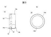
- the clutch cover 14 of the one-way clutch 10 is formed of a thin metal plate material, and has a cylindrical outer peripheral surface 14a and a disk-like portion 14b extending continuously from the outer peripheral surface toward the inner peripheral side.
- the outer peripheral surface and the disc-shaped portion are bent at a right angle.
- the disk-like portion 14b wraps around the roller 11 constituting the one-way clutch 10 and a constituent member such as a disk adjacent to the roller to prevent the drop-out, and the end portion 14c on the outer peripheral surface opposite to the disk-like portion 14b.
- the one-way clutch 10 is integrated by bending inward.
- a plurality of through holes 15 are formed through the outer peripheral surface 14a of the clutch cover 14 as a rotational speed detected portion for detecting the rotational speed.
- a plurality of through holes are formed at equal intervals on the circumference of the outer peripheral surface. Since the clutch cover 14 is in close contact with the outer peripheral surface of the clutch outer 13, the depth of the through hole is shallow because the clutch cover 14 is thin, and the depth d1 is equal to the plate thickness of the clutch cover 14. It has become. For example, when the thickness of the metal plate constituting the clutch cover is 0.5 mm, the depth d1 of the through hole 15 is 0.5 mm.
- a circumferential annular groove 16 is formed on the outer circumferential surface of the clutch outer 13 along the same circumference in accordance with the through hole 15 of the clutch cover 14.
- the depth of the annular groove 16 depends on the performance of the sensor used, it is preferably about 2 to 3 mm to 5 mm.
- the depth of the through hole 15 is The thickness d1 of the clutch cover and the depth d2 of the annular groove 16 are the total depth. The depth of the annular groove may be set deeper.
- a magnet switch 21 is fixed to the side of the starter 5.
- the magnet switch is configured to energize an internal plunger coil to attract the plunger, push out the pinion 7 by a drive lever, and mesh with the ring gear 3. Accordingly, the engine can be started by engaging the pinion 7 with the ring gear 3 and rotating the starter 5.
- the control device 20 is connected to the signal line 8a from the rotational speed detection sensor 8 located on the outer periphery of the one-way clutch 10 and the signal line 9a from the rotational speed detection sensor 9 that detects the rotational speed of the ring gear 3. Yes.
- a power line 5a for supplying power to the relay 4a from a drive unit (DRV) of the control device 20 and a power line 21a for supplying power to the magnet switch 21 are connected.
- the operation of the starter 5 of this embodiment will be described.
- the engine 1 When the engine 1 is started, power is supplied to the magnet switch 21 by a signal from the control device 20, the plunger is sucked, the drive lever pushes the pinion 7 and meshes with the ring gear 3, and from the battery 4 via the relay 4a.
- the starter 5 is supplied with power and rotates. With this rotation, the ring gear 3 is rotated and the engine 1 is started.
- the rotation of the ring gear 3 is not transmitted to the starter 5 side by the one-way clutch 10, and the power supply to the starter 5 is stopped.
- the control device 20 temporarily stops the engine 1 when a condition permitting the temporary stop of the engine is satisfied, such as when the vehicle is stopped at an intersection or the like, and when the restart condition is satisfied, It can be rotated to restart the engine.
- the control device 20 is detected by the rotational speed detection sensor 8 that detects the rotational speed detected by the rotational speed detection sensor 9 connected to the crankshaft 2 of the engine 1 and the rotational speed of the pinion 7 linked to the starter 5. For example, when the starter 5 is rotated and the peripheral speeds of the pinion 7 and the ring gear 3 substantially coincide with each other, the pinion 7 and the ring gear 3 are engaged to start the engine 1.
- the engine 1 When the vehicle stops while driving, the engine 1 is in an idling operation state. When the conditions for stopping the engine are satisfied in this state, for example, when a predetermined time has elapsed, the engine 1 is stopped to reduce fuel consumption. While the vehicle is stopped, the engine 1 is restarted when the conditions for engine restart are satisfied.
- the controller 20 performs temporary stop and restart of the engine. When the engine is restarted due to a restart request, the peripheral speed of the pinion 7 and the peripheral speed of the ring gear 3 are substantially the same even when the engine speed is decreasing. And can be restarted quickly without causing any meshing problems.
- the signal detection through-hole 15 of the present embodiment has a depth of the bottom surface of the through-hole 15 as d ⁇ b> 2, and the outer peripheral portion of the clutch cover 14 from the rotational speed detection sensor 8.
- L1 is the distance from the rotational speed detection sensor 8 to the outer periphery of the clutch outer 13
- L3 is the distance from the rotational speed detection sensor 8 to the bottom surface of the annular groove 16 of the clutch outer 13. ⁇ L2 ⁇ L3.
- the clutch cover 14 is temporarily covered with the outer periphery of the clutch outer 13 without providing a through hole in the clutch cover 14, and then the portion of the clutch cover 14 positioned above the annular groove 16 with a punch or the like is attached to the annular groove 16. It is good also as a rotational speed detected part by pressing inside and providing a recessed part on the clutch cover 14 concerned.
- the control device 20 rotates the pinion 7, obtains the peripheral speed from the rotational speed of the pinion 7 detected by the rotational speed detection sensor 8, obtains the peripheral speed from the rotational speed of the ring gear 3 detected by the rotational speed detection sensor 9,
- the magnet switch 21 is operated to move the pinion 7 in the axial direction so that the pinion 7 and the ring gear 7 are engaged. Since the peripheral speeds of the two gears are the same, the two gears mesh smoothly with each other without generating abnormal noise, and the engine 1 can be started quickly.
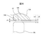
- FIG. 6 is a cross-sectional view showing the main part of another embodiment of the starter.
- this embodiment is characterized in that the rotational speed detected portion for detecting the rotational speed by the rotational speed detection sensor is only a through hole, compared to the above-described embodiment.
- Other substantially equivalent configurations are denoted by the same reference numerals, and detailed description thereof is omitted.
- the one-way clutch 10A is configured such that no annular groove is formed on the outer peripheral surface of the clutch outer 13A.
- the material of the clutch cover 14A a material having a glossy surface such as a plated steel plate, the outer peripheral portion can reflect light.
- the surface of the clutch outer 13A is dark-colored.
- the rotational speed detection sensor 8A is an optical sensor.
- FIG. 7A and 7B show still another embodiment of the starter, wherein FIG. 7A is a front view in which a part of the one-way clutch is broken, and FIG. 7B is a cross-sectional view showing the main part.
- this embodiment is different from the above-described embodiment in that the rotational speed detected part for detecting the rotational speed by the rotational speed detection sensor is only the recess.
- Other substantially equivalent configurations are denoted by the same reference numerals, and detailed description thereof is omitted.
- the one-way clutch 10B has no clutch cover on the outer periphery of the clutch outer 13B, and the rotational speed detection sensor 8B is directly opposed to the outer peripheral surface of the clutch outer.
- a plurality of recesses 17 are formed at equal intervals on the outer circumference of the clutch outer 13B. The depth of the recess 17 is d3, and this depth is set deeper than the distance L6 between the clutch outer 13B and the rotational speed detection sensor 8.
- the unevenness is formed by the step between the recess 17 formed on the circumference of the outer peripheral surface and the outer peripheral surface, and the magnetic force from the sensor is applied to the unevenness.
- the uneven state is detected as a pulse. Since this uneven signal is detected by the sum L7 of the interval L6 and the depth d3 of the recess, the level of signal detection is increased, and a stable rotational speed signal is obtained. Therefore, the weight can be reduced with a simple configuration, and the engine can be started quickly.
- the through hole or the concave portion is described as the rotational speed detected portion.
- a non-magnetic material and a magnetic material are embedded alternately (preferably at equal intervals) on the clutch cover, and their magnetic properties are obtained. It is good also as a form which a magnetic sensor detects a rotational speed by a change.
- a bright portion and a dark portion may be alternately (preferably equidistantly) installed on the clutch cover, and the optical sensor may detect the rotational speed based on a change in the reflectance thereof.
- the rotation speed detection signal can be detected as it is, and since it is not necessary to provide additional parts, the rotation speed of the pinion can be detected without extending the axial dimension of the starter.
- a space having a predetermined depth is added to the clutch outer, so that the predetermined space between the outer periphery of the clutch cover and the clutch outer is increased. Can be detected up to the bottom diameter, and the signal detection performance of the rotational speed can be greatly improved. That is, the rotation speed can be reliably detected.
- the gloss treatment is applied to the clutch cover, the reflectivity of the clutch cover is increased, and the inside of the through hole is dark and the reflectivity is decreased.
- the light / dark ratio increases, so that the amplitude of the signal increases and a signal with a stable rotational speed can be obtained.
- the clutch cover has a disk-shaped portion extending continuously from the outer peripheral surface to the inner peripheral side, and the disk-shaped portion is formed so as to wrap a member constituting the one-way clutch. . That is, since the members constituting the one-way clutch are wrapped and held by the disc-shaped portion of the clutch cover, the one-way clutch can be integrated with a simple configuration.
- the rotation speed of the pinion and the rotation speed of the engine are compared. For example, when both the peripheral speeds coincide with each other, the pinion is engaged with the ring gear and the starter is rotated to restart the engine. Thus, the engine can be started smoothly and quickly without generating abnormal noise when the gears are engaged.
Landscapes
- Engineering & Computer Science (AREA)
- Chemical & Material Sciences (AREA)
- Combustion & Propulsion (AREA)
- Mechanical Engineering (AREA)
- General Engineering & Computer Science (AREA)
- Microelectronics & Electronic Packaging (AREA)
- Power Engineering (AREA)
- Combined Controls Of Internal Combustion Engines (AREA)
- Connection Of Motors, Electrical Generators, Mechanical Devices, And The Like (AREA)
Abstract
ワンウェイクラッチのクラッチアウタの外周に、クラッチカバーを有する場合でも、安定した回転速度信号を検出できる車両用エンジンの始動装置を提供するために、スタータ5の回転駆動力を、スタータのピニオン7によってエンジンのクランク軸のリングギヤ3に係脱可能に噛み合い伝達する車両用エンジンの始動装置Dは、ピニオン7とスタータ5のアーマチャシャフト6aとの間に配置されたワンウェイクラッチ10と、ピニオン7の回転速度を検出する回転速度検出装置とを備えている。ワンウェイクラッチのクラッチアウタ13の外周面は薄肉のクラッチカバー14で覆われ、回転速度被検出部はクラッチカバー14の円周上に形成された貫通孔15と、貫通孔が形成された円周上に沿って、クラッチアウタの外周面に形成された円周状の溝16とで形成され、回転速度検出センサ8は、貫通孔15及び溝16に対向して配置される。
Description
本発明は、アイドリングストップ用のスタータに関する。
一般に、エンジンを始動する場合、エンジンをクランキングするためにスタータの動力をエンジンへ伝達するピニオンを、ソレノイドコイルによって押し出して、ピニオンをエンジンのクランク軸に連結されたリングギヤに噛み込ませて、スタータの動力にてエンジンをクランキングする。アイドリングストップ用のスタータにおいては、車両が一時停止する際、エンジンが停止状態になってから、ピニオンを押し出してリングギヤに噛み込ますようにしている。ここで、運転者は、一時停止をしようとしたが、急に考えを変えて再始動要求を出す場合がある。しかし、エンジン回転が降下中に再始動要求が発生しても、エンジン回転が停止状態になるまで再始動を行えず、再始動を行うまでに時間の遅れが発生してしまう。
このため、特許第4214401号公報(特許文献1)では、エンジン回転が降下中に再始動要求が発生した際、スタータへ通電してピニオンを空転させ、ピニオンとリングギヤの回転速度を各々検出し、各々の回転が同期する時点でピニオンを押し出してリングギヤに噛み込ますようにして、俊敏にエンジンの再始動を行っている。特許第4237150号公報(特許文献2)では、スタータ用ワンウェイクラッチのクラッチアウタの筒形外周壁の外周面に凸凹状の信号出力部を形成し、信号検出用のセンサでクランク軸の回転速度を検出している。
特許文献1には、ピニオンの回転速度の具体的な検出方法については記載されていない。又、特許文献2のセンサはクランク軸の回転速度を検出するものであり、ピニオンの回転速度を検出するものではない。即ち、従来技術では、アイドリングストップ用のスタータに搭載されるピニオンの回転速度を具体的に検出する方法について考慮されていない、という課題がある。
そこで、本発明の目的は、ピニオンの回転速度を検出することができるアイドリングストップ用のスタータを提供することにある。
上記課題を解決するため、本発明の望ましい態様の1つは次の通りである。
本スタータは、スタータの回転駆動力をエンジンのクランク軸のリングギヤに伝達するピニオンと、ピニオンをリングギヤに押し出すアーマチャシャフトと、エンジンの回転駆動力がアーマチャに伝わらないように、ピニオンとリングギヤの間に配置されたワンウェイクラッチと、ピニオンの回転速度を検出する回転速度検出装置と、を備え、回転速度検出装置は、ワンウェイクラッチの周囲に形成された回転速度被検出部と、該回転速度被検出部を検出する回転速度検出センサと、を備える。
本発明によれば、ピニオンの回転速度を検出することができるアイドリングストップ用のスタータを提供することができる。
以下、一実施形態を図面に基づき詳細に説明する。図1~4において、エンジン1のクランク軸2には、リングギヤ3が取り付けられている。一方、エンジン1を始動するための回転駆動力を発生するスタータ5には、内部にアーマチャ6が回転可能に支持されており、アーマチャシャフト6aの一端にピニオン7が取り付けられている。このピニオン7が、リングギヤ3に係脱可能に噛み合うことによって、スタータ5の回転駆動力をエンジン1に伝達することができる。スタータ5には、ピニオン7の回転速度を検出する回転速度検出センサ8が設置されている。
図1に示されるシステムは、エンジン1、エンジン1のクランク軸2に固定されたリングギヤ3、リングギヤ3に噛み合うピニオン7を備えるスタータ5、スタータ5の電源であるバッテリ4、リレー4a、及び、回転速度検出センサ8とから構成される。又、エンジンを一時自動停止後、自動再始動させるため、更にエンジンの回転速度を検出するためのリングギヤ3の回転速度検出センサ9を含んで構成され、制御装置20が、車両の運転中にエンジンの一時停止が許容される条件が成立した時、エンジンを一時停止させ、再始動条件が成立した時、スタータ5を回転させてエンジン1を再始動させる。
図2において、スタータ5は、直流電動機であり、内蔵するアーマチャ6がバッテリ4からの通電を受けて回転駆動力を発生する。アーマチャ6により発生した回転駆動力は、スタータ5の出力軸であるアーマチャシャフト6aに伝達される。アーマチャシャフト6aとピニオン7との間には、エンジン1が始動した後、エンジン1の回転駆動力がアーマチャ6に伝わらないように、ワンウェイクラッチ10が配置されている。ワンウェイクラッチ10の外周部の径方向の外側(エンジン1側)から対向する位置に、回転速度検出センサ8が配置されており、ワンウェイクラッチ10の回転信号を検出する。本実施形態では磁気センサが用いられている。
ワンウェイクラッチ10は、ピニオン7と、ローラ11を介して半径方向に対向して同軸上に配置されたクラッチインナ12とクラッチアウタ13とクラッチカバー14を有している。クラッチインナ12はピニオン7と一体に構成されており、エンジン1を始動する際にアーマチャシャフト6aを介して回転駆動される。
ワンウェイクラッチ10は、アーマチャシャフト6aに形成されたスプライン(図示せず)に嵌合され、軸方向に移動可能となっている。ワンウェイクラッチ10は、スタータ5のエンジン1からの連れ廻りを防止する。クラッチアウタ13は、ピニオン7と一体となって回転するクラッチインナ12とワンウェイクラッチ10の機能により、エンジン回転から切り離される。そして、ローラ11は、クラッチインナ12とクラッチアウタ13の間を結合・分離する。クラッチアウタ13の外周面は、クラッチカバー14に覆われ、外嵌されている。
クラッチアウタ13は、アーマチャシャフト6aに嵌合する軸受部13a、軸受部13aの一端から外周方向に延在するディスク部13b、及び、ディスク部13bの外周より水平方向に延在する外周部13cとを備えており、外周部13cの内周面とクラッチインナ12の外周面との間にローラ11が介在されている。この構成により、クラッチアウタ13の一方向の回転はローラ11を介してクラッチインナ12に伝達され、クラッチアウタ13が他方向に回転する時はクラッチインナ12に伝達しない構成となっている。そして、エンジンが始動してリングギヤ3の周回転速度がピニオンの周回転速度を上回る場合は、この回転はスタータ5側に伝達されない。即ち、ワンウェイクラッチ10は一方向の回転のみ伝達し、クラッチアウタ13の回転数とピニオン7の回転数とは同じとなり、他方向の回転はローラがクラッチインナから開放されてフリーの状態となる。
ワンウェイクラッチ10のクラッチカバー14は、薄肉の金属板材から形成され、円筒状の外周面14aと、この外周面に連続して内周側に延在する円板状部14bとを有しており、外周面と円板状部とは直角に折り曲げられている。この円板状部14bは、ワンウェイクラッチ10を構成するローラ11や、ローラに隣接するディスク等の構成部材を包み込んで脱落を防止し、円板状部14bと反対側の外周面の端部14cを内側に折り曲げることでワンウェイクラッチ10を一体化している。
クラッチカバー14の外周面14aには、回転速度を検出するための回転速度被検出部として複数の貫通孔15が貫通して形成されている。この貫通孔は外周面の円周上に等間隔で複数個が形成されている。この貫通孔は、クラッチカバー14がクラッチアウタ13の外周面に密着しているため、クラッチカバー14が薄肉であることから、その深さは浅く、クラッチカバー14の板厚分だけの深さd1となっている。例えば、クラッチカバーを構成する金属板材の厚さが0.5mmの場合は、貫通孔15の深さd1は0.5mmとなる。
クラッチアウタ13の外周面には、クラッチカバー14の貫通孔15に合わせて、同じ円周上に沿って円周状の環状溝16が形成されている。環状溝16の深さは、使用するセンサの性能にもよるが、2~3mm程度から5mm程度が好ましく、クラッチカバー14とクラッチアウタ13とが一体となった状態では貫通孔15の深さは、クラッチカバーの厚さ分d1と環状溝16の深さ分d2が合計された深さとなる。尚、環状溝の深さは更に深く設定してもよい。
スタータ5の側部にはマグネットスイッチ21が固定されている。マグネットスイッチは、内部のプランジャコイルに通電してプランジャを吸引し、ドライブレバーによってピニオン7を押し出してリングギヤ3に噛み合わせる構成となっている。従って、リングギヤ3にピニオン7を噛み合わせてスタータ5を回転させることでエンジンを始動できる。
制御装置20は、ワンウェイクラッチ10の外周に位置している回転速度検出センサ8からの信号線8a、及び、リングギヤ3の回転速度を検出する回転速度検出センサ9からの信号線9aに接続されている。又、制御装置20の駆動部(DRV)から、リレー4aへ電源を供給するための電源線5aと、マグネットスイッチ21に電源を供給するための電源線21aが接続されている。
次に、本実施形態のスタータ5の動作について説明する。エンジン1を始動する時は、制御装置20からの信号によりマグネットスイッチ21に電源が供給され、プランジャが吸引されてドライブレバーがピニオン7を押し出してリングギヤ3に噛み合わせ、リレー4aを介しバッテリ4からスタータ5に電源が供給されて回転し、この回転でリングギヤ3を回転させてエンジン1を始動する。エンジンが始動すると、リングギヤ3の回転はワンウェイクラッチ10でスタータ5側へ伝達されず、スタータ5への電源供給は停止される。
次に、回転速度検出センサ8、及び回転速度検出センサ9で検出される回転速度を使用する例について、以下に説明する。制御装置20は、車両の運転中に交差点等で停止した時等、エンジンの一時停止が許容される条件が成立した時、エンジン1を一時停止させ、再始動条件が成立した時、スタータ5を回転させてエンジンを再始動させることができる。
制御装置20は、エンジン1のクランク軸2に連結された回転速度検出センサ9で検出された回転速度と、スタータ5に連動するピニオン7の回転速度を検出する回転速度検出センサ8で検出された回転速度とを比較して、例えば、スタータ5を回転させてピニオン7とリングギヤ3の周速度が略一致した時にピニオン7とリングギヤ3とを噛み合わせてエンジン1を始動する。
車両を運転中に、交差点等で停止した時、エンジン1はアイドリング運転状態となる。この状態でエンジン停止の条件が整った時、例えば所定時間が経過した時にはエンジン1は停止され、燃料消費を低減する。このような車両の停止中に、エンジン再始動の条件が整った時にはエンジン1は再始動される。エンジンの一時停止と、再始動については、制御装置20が行う。再始動要求がありエンジン再始動する際に、エンジンの回転速度が降下中であっても、ピニオン7の周速度とリングギヤ3の周速度が略一致しているため、ギヤの噛み合い時の異音や噛み合いの不具合を起こすことなく迅速に再始動することができる。
又、ピニオン7の周速度とリングギヤ3の周速度が一致していなくても、エンジン停止中の回転速度の降下分を予測し、予測された回転速度でピニオン7をリングギヤ3に噛み合わせることで迅速に再始動を実行することができる。更に、リングギヤ3の回転速度の降下と、始動時のスタータのピニオン7の回転速度の上昇を予測して、リングギヤにピニオンを噛み合わせることも可能となる。
本実施形態の信号検出用の貫通孔15は、図5に示されるように、貫通孔15の底面の深さがd2と深く形成されており、回転速度検出センサ8からクラッチカバー14の外周部までの距離をL1とし、回転速度検出センサ8からクラッチアウタ13の外周部までの距離をL2とし、回転速度検出センサ8からクラッチアウタ13の環状溝16の底面までの距離をL3とすると、L1<L2<L3となる。
回転速度検出センサ8に磁気センサを用いる場合、信号検出はL1とL3で行われ、クラッチアウタ13の外周部に形成された環状溝16が無い場合の信号検出L1とL2に比べて、大幅に安定した信号検出が可能となる。又、貫通孔15の深さを深くして信号を安定させるための環状溝16はクラッチアウタ13の外周面に円周方向に形成するので、クラッチアウタの成型時に同時に形成することができ、簡単な構成で軽量化も図ることができる。
尚、クラッチカバー14に貫通孔を設けずに、一旦クラッチアウタ13の外周部にクラッチカバー14を覆い被せた後、ポンチ等で環状溝16の上部に位置するクラッチカバー14の部分を環状溝16内部に押し付けて、クラッチカバー14上に凹部を設けることで、当該凹部を回転速度被検出部としてもよい。
制御装置20はピニオン7を回転させ、回転速度検出センサ8で検出されたピニオン7の回転速度から周速度を求め、回転速度検出センサ9で検出されたリングギヤ3の回転速度から周速度を求め、ピニオン7の周速度とリングギヤ3の周速度が一致した時、マグネットスイッチ21を作動させてピニオン7を軸方向に移動してピニオン7とリングギヤ7とを噛み合わせる。2つのギヤは互いに周速度が同じであるため、異音等が発生することなく、滑らかに噛み合い、エンジン1の迅速な始動が可能となる。
他の実施形態を図6に基づき詳細に説明する。図6はスタータの他の実施形態の要部を示す断面図である。尚、この実施形態は前記した実施形態に対し、回転速度検出センサで回転速度を検出する回転速度被検出部が貫通孔だけであることを特徴とする。そして、他の実質的に同等の構成については同じ符号を付して詳細な説明は省略する。
この実施形態では、ワンウェイクラッチ10Aは、クラッチアウタ13Aの外周面に環状溝が形成されない構成となっている。クラッチカバー14Aの材質をメッキ鋼板などの表面が光沢面である材料とすることで、外周部は光を反射することができる。そして、クラッチアウタ13Aは表面が暗色処理されている。具体的には、クラッチアウタ13Aはワンウェイクラッチ10Aの剛性上から熱処理を行う結果、クラッチアウタ13Aの外周部は光を反射しにくい黒い色となる。そして、この実施形態では、回転速度検出センサ8Aは光学式センサが用いられる。
この結果、クラッチアウタ13Aに形成された貫通孔の深さを増やすための溝が形成されず、回転速度検出センサ8Aとクラッチカバー14Aとの間隔L4と、回転速度検出センサ8Aとクラッチアウタ13Aとの間隔L5との間隔に大きな差がなくても、回転速度検出センサ8Aに光学式センサを用いる場合、光を反射させるための追加部材を用いることなく、安定した信号検出が可能となる。
尚、光沢処理されたクラッチカバー14Aと暗色処理されたクラッチアウタ13Aで安定した信号を得ることができる例を示したが、クラッチカバーを白色等の明色処理しておき、クラッチカバーの貫通孔から露出するクラッチアウタの表面を暗色処理しておき、明暗を強調することで得られる信号を安定化させることもできる。
更に他の実施形態を図7に基づき詳細に説明する。図7はスタータの更に他の実施形態を示し、(a)はワンウェイクラッチの一部を破断した正面図、(b)は要部を示す断面図である。尚、この実施形態は前記した実施形態に対し、回転速度検出センサで回転速度を検出する回転速度被検出部が凹部だけである。そして、他の実質的に同等の構成については同じ符号を付して詳細な説明は省略する。
この実施形態では、ワンウェイクラッチ10Bは、クラッチアウタ13Bの外周にクラッチカバーがなく、クラッチアウタの外周面に直接回転速度検出センサ8Bが対向して配置されている。そして、クラッチアウタ13Bの外周面には、円周上に複数の凹部17が等間隔で形成されている。凹部17の深さはd3であり、この深さはクラッチアウタ13Bと回転速度検出センサ8との間隔L6より深く設定されている。
このように構成された本実施形態では、クラッチアウタ13Bが回転すると、外周面の円周上に形成された凹部17と外周面との段差により凹凸が形成され、この凹凸にセンサからの磁力が作用して、凹凸状態がパルスとなって検出される。この凹凸状態の信号は、間隔L6と凹部の深さd3との和L7とにより検出されるため、信号検出のレベルが大きくなって安定した回転速度の信号が得られる。このため、簡単な構成で軽量化でき、迅速なエンジンの始動が可能となる。
尚、上記実施例では、貫通孔又は凹部を回転速度被検出部にするとして説明したが、クラッチカバー上に、非磁性体と磁性体を交互に(好ましくは等間隔に)埋め込み、それらの磁気変化により、磁気センサが回転速度を検出する形態としてもよい。又、クラッチカバー上に明部と暗部を交互に(好ましくは等間隔に)設置し、それらの反射率の変化により、光学センサが回転速度を検出する形態としてもよい。
本実施例によれば、クラッチカバーを有したワンウェイクラッチを装着したスタータであっても、パルサーギヤのような回転速度検出のための回転部材をスタータの回転軸に設ける必要はなくなり、既存の部品構成のまま回転速度検出用の信号を検出できると共に、追加部品を設ける必要がないため、スタータの軸方向寸法を延長することなく、ピニオンの回転速度の検出が可能となる。
又、クラッチカバーの外周部の信号検出部の肉厚のみで検出する場合に比べて、クラッチアウタに所定の深さを有する空間が加わることにより、クラッチカバーの外周部とクラッチアウタの所定の空間の底径までを検出することができ、回転速度の信号検出性能を大幅に向上させることができる。即ち、回転速度の検出を確実に行うことができる。
又、クラッチカバーに光沢処理を行えば、クラッチカバーの反射率が高くなり、貫通孔の内部は暗色で反射率が低くなる。即ち、光学センサを用いれば、明暗の比が大きくなるため信号の振幅が大きくなって安定した回転速度の信号を得ることができる。
又、クラッチカバーは、外周面に連続して内周側に延在する円板状部を有しており、該円板状部は、ワンウェイクラッチを構成する部材を包み込むように形成されている。即ち、ワンウェイクラッチを構成する部材はクラッチカバーの円板状部で包み込まれて保持されるため、簡単な構成でワンウェイクラッチを一体化することができる。
又、ピニオンの回転速度とエンジンの回転速度を比較して、例えば両方の周速度が一致した時にピニオンをリングギヤに噛み合わせてスタータを回転させてエンジンを再始動するため、運転者の要求に沿って迅速に、しかもギヤの噛み合い時に異音を発生することなく、滑らかにエンジンを始動させることができる。
以上、本発明の実施形態について詳述したが、本発明は、前記の実施形態に限定されるものではなく、特許請求の範囲に記載された本発明の精神を逸脱しない範囲で、種々の設計変更を行うことができる。例えば、前記の実施形態では、回転速度検出センサとして磁気センサの例を示したが、受光素子等を用いた光学式センサや音波等を用いたセンサ等、各種のセンサを用いることができる。
1:エンジン、2:クランク軸、3:リングギヤ、4:バッテリ、4a:リレー、5:スタータ、6:アーマチャ、6a:アーマチャシャフト、7:ピニオン、8,8A:回転速度検出センサ、9:回転速度検出センサ、10,10A,10B:ワンウェイクラッチ、11:ローラ、12:クラッチインナ、13,13A,13B:クラッチアウタ、14,14A:クラッチカバー、14a:外周面、14b:円板状部、14c:端部、15:貫通孔(クラッチカバーの回転速度被検出部)、16:クラッチアウタの外周面の環状溝、17:凹部、20:制御装置、21:マグネットスイッチ、d1:貫通孔の深さ、d2:環状溝の深さ、d3:凹部の深さ
Claims (11)
- スタータの回転駆動力をエンジンのクランク軸のリングギヤに伝達するピニオンと、
前記ピニオンを前記リングギヤに押し出すアーマチャシャフトと、
前記エンジンの回転駆動力が前記アーマチャに伝わらないように、前記ピニオンと前記リングギヤの間に配置されたワンウェイクラッチと、
前記ピニオンの回転速度を検出する回転速度検出装置と、を備え、前記回転速度検出装置は、前記ワンウェイクラッチの周囲に形成された回転速度被検出部と、
該回転速度被検出部を検出する回転速度検出センサと、を備える、スタータ。 - 前記回転速度被検出部は、前記ワンウェイクラッチのクラッチアウタの外周面に形成される、請求項1記載のスタータ。
- 前記回転速度被検出部は、凹部であり、
前記回転速度検出センサは、前記凹部に対向して配置されている、請求項2記載のスタータ。 - 前記凹部は、前記クラッチアウタの外周面の円周上に沿って等間隔に複数個形成されている、請求項3記載のスタータ。
- 前記クラッチアウタの外周面は、クラッチカバーで覆われ、
前記回転速度被検出部は、前記クラッチカバーの円周上に形成された貫通孔と、該貫通孔が形成された円周上に沿って、前記クラッチアウタの外周面に形成された円周状の溝と、で形成され、
前記回転速度検出センサは、前記貫通孔及び前記溝に対向して配置されている、請求項1記載のスタータ。 - 前記クラッチアウタの外周面は、暗色に形成され、光沢を有するクラッチカバーで覆われ、
前記回転速度被検出部は、前記クラッチカバーの円周上に形成された貫通孔であり、
前記回転速度検出センサは、前記貫通孔に対向して配置されている、請求項1記載のスタータ。 - 前記クラッチカバーは、前記外周面に連続して内周側に延在する円板状部を有しており、該円板状部は、前記ワンウェイクラッチを構成する部材を包み込むように形成されている、請求項5又は6記載のスタータ。
- 前記貫通孔は、前記クラッチカバーの外周面に、その円周上に沿って等間隔に複数個形成されている、請求項5又は7記載のスタータ。
- 前記回転速度検出センサが検出した前記ピニオンの回転速度と前記エンジンの回転速度検出センサで検出したエンジンの回転速度とに基づいて、前記ピニオンを前記リングギヤに噛み合わせてエンジンを始動させるべく、前記ピニオンを移動させる制御をする制御装置を更に備える、請求項1から8の何れか一項に記載のスタータ。
- 前記制御装置は、前記ピニオンの回転速度から求めた周速度と前記リングギヤの回転速度から求めた周速度とが一致した時に、前記ピニオンを移動させる、請求項9記載のスタータ。
- 前記制御装置は、前記エンジンが一時自動停止後で、該エンジンの前駆クランク軸が回転している状態でエンジンを自動再始動する場合、前記スタータを回転駆動させる制御を行った後、前記ピニオンと前記リングギヤの周速度とが一致した時、前記リングギヤに前記ピニオンを噛み合わせるべく、前記ピニオンを移動させる、請求項10記載のスタータ。
Priority Applications (3)
| Application Number | Priority Date | Filing Date | Title |
|---|---|---|---|
| CN201080063670.8A CN102770662B (zh) | 2010-03-02 | 2010-08-25 | 起动机 |
| EP10847030.3A EP2543873A4 (en) | 2010-03-02 | 2010-08-25 | Starter |
| US13/574,743 US9203287B2 (en) | 2010-03-02 | 2010-08-25 | Starter having optical speed sensor on clutch outer periphery |
Applications Claiming Priority (2)
| Application Number | Priority Date | Filing Date | Title |
|---|---|---|---|
| JP2010045615A JP5362621B2 (ja) | 2010-03-02 | 2010-03-02 | スタータ |
| JP2010-045615 | 2010-03-02 |
Publications (1)
| Publication Number | Publication Date |
|---|---|
| WO2011108133A1 true WO2011108133A1 (ja) | 2011-09-09 |
Family
ID=44541809
Family Applications (1)
| Application Number | Title | Priority Date | Filing Date |
|---|---|---|---|
| PCT/JP2010/064406 Ceased WO2011108133A1 (ja) | 2010-03-02 | 2010-08-25 | スタータ |
Country Status (5)
| Country | Link |
|---|---|
| US (1) | US9203287B2 (ja) |
| EP (1) | EP2543873A4 (ja) |
| JP (1) | JP5362621B2 (ja) |
| CN (1) | CN102770662B (ja) |
| WO (1) | WO2011108133A1 (ja) |
Cited By (1)
| Publication number | Priority date | Publication date | Assignee | Title |
|---|---|---|---|---|
| WO2013088941A1 (ja) * | 2011-12-14 | 2013-06-20 | 日産自動車株式会社 | 車両のエンジン自動停止制御装置 |
Families Citing this family (5)
| Publication number | Priority date | Publication date | Assignee | Title |
|---|---|---|---|---|
| DE112012004750T5 (de) | 2011-11-15 | 2014-10-02 | Remy Technologies, Llc | Startersystem |
| US9435312B2 (en) * | 2013-03-15 | 2016-09-06 | Remy Technologies, Llc | Diagnostic system and method for vehicle starter |
| CN103321812B (zh) * | 2013-04-09 | 2016-03-30 | 浙江吉利汽车研究院有限公司杭州分公司 | 发动机启动控制系统 |
| JP2015102031A (ja) * | 2013-11-26 | 2015-06-04 | 株式会社デンソー | エンジン始動装置 |
| EP3480482B1 (en) * | 2016-06-30 | 2021-01-20 | GKN Automotive Limited | Slide flange |
Citations (5)
| Publication number | Priority date | Publication date | Assignee | Title |
|---|---|---|---|---|
| JPH0544523A (ja) * | 1991-08-14 | 1993-02-23 | Hitachi Ltd | 回転センサ内蔵スタータ |
| JPH0683958U (ja) * | 1993-05-21 | 1994-12-02 | 三菱自動車工業株式会社 | キースイッチ誤操作防止装置 |
| JP2000314364A (ja) * | 1999-04-01 | 2000-11-14 | Robert Bosch Gmbh | 内燃機関の始動のための始動装置 |
| JP4214401B2 (ja) | 2004-05-18 | 2009-01-28 | 株式会社デンソー | エンジン自動停止再始動装置 |
| JP4237150B2 (ja) | 2005-02-21 | 2009-03-11 | 川崎重工業株式会社 | 車輌用エンジンの信号検出装置 |
Family Cites Families (6)
| Publication number | Priority date | Publication date | Assignee | Title |
|---|---|---|---|---|
| JP2856989B2 (ja) | 1992-09-01 | 1999-02-10 | 株式会社リコー | 領域境界の内外ループ識別方法 |
| EP1401752B1 (en) * | 2001-06-19 | 2011-08-17 | Delphi Technologies, Inc. | Cable drive assembly |
| US20030106766A1 (en) * | 2001-12-10 | 2003-06-12 | Johnson Joseph M. | Power operation for opening and closing a panel and a method of controlling a power operator |
| JP4269642B2 (ja) * | 2002-10-28 | 2009-05-27 | 日本精工株式会社 | モータ用センサ付き転がり軸受 |
| US7616126B2 (en) * | 2006-07-18 | 2009-11-10 | Gentex Corporation | Optical particle detectors |
| US8561588B2 (en) * | 2008-03-07 | 2013-10-22 | GM Global Technology Operations LLC | Engine stop/start system and method of operating same |
-
2010
- 2010-03-02 JP JP2010045615A patent/JP5362621B2/ja not_active Expired - Fee Related
- 2010-08-25 EP EP10847030.3A patent/EP2543873A4/en not_active Withdrawn
- 2010-08-25 US US13/574,743 patent/US9203287B2/en not_active Expired - Fee Related
- 2010-08-25 CN CN201080063670.8A patent/CN102770662B/zh not_active Expired - Fee Related
- 2010-08-25 WO PCT/JP2010/064406 patent/WO2011108133A1/ja not_active Ceased
Patent Citations (5)
| Publication number | Priority date | Publication date | Assignee | Title |
|---|---|---|---|---|
| JPH0544523A (ja) * | 1991-08-14 | 1993-02-23 | Hitachi Ltd | 回転センサ内蔵スタータ |
| JPH0683958U (ja) * | 1993-05-21 | 1994-12-02 | 三菱自動車工業株式会社 | キースイッチ誤操作防止装置 |
| JP2000314364A (ja) * | 1999-04-01 | 2000-11-14 | Robert Bosch Gmbh | 内燃機関の始動のための始動装置 |
| JP4214401B2 (ja) | 2004-05-18 | 2009-01-28 | 株式会社デンソー | エンジン自動停止再始動装置 |
| JP4237150B2 (ja) | 2005-02-21 | 2009-03-11 | 川崎重工業株式会社 | 車輌用エンジンの信号検出装置 |
Non-Patent Citations (1)
| Title |
|---|
| See also references of EP2543873A4 |
Cited By (1)
| Publication number | Priority date | Publication date | Assignee | Title |
|---|---|---|---|---|
| WO2013088941A1 (ja) * | 2011-12-14 | 2013-06-20 | 日産自動車株式会社 | 車両のエンジン自動停止制御装置 |
Also Published As
| Publication number | Publication date |
|---|---|
| JP2011179437A (ja) | 2011-09-15 |
| US9203287B2 (en) | 2015-12-01 |
| EP2543873A1 (en) | 2013-01-09 |
| JP5362621B2 (ja) | 2013-12-11 |
| US20130119831A1 (en) | 2013-05-16 |
| CN102770662A (zh) | 2012-11-07 |
| CN102770662B (zh) | 2015-03-25 |
| EP2543873A4 (en) | 2017-09-06 |
Similar Documents
| Publication | Publication Date | Title |
|---|---|---|
| JP5362621B2 (ja) | スタータ | |
| CN101210534B (zh) | 起动机 | |
| US20110139108A1 (en) | Control of a pre-spun starter | |
| JP5566530B2 (ja) | エンジン始動装置およびエンジン始動方法 | |
| JP5218618B2 (ja) | エンジン始動装置 | |
| JP4591842B2 (ja) | 電動式可変バルブタイミング装置の制御装置 | |
| US9334845B2 (en) | Engine starting device | |
| JP5409487B2 (ja) | スタータシステム | |
| CN104728015B (zh) | 发动机起动设备 | |
| JP2015172353A (ja) | エンジン始動装置 | |
| JPWO2016071968A1 (ja) | エンジン始動装置 | |
| US10676102B2 (en) | Control system for hybrid vehicle | |
| JP4238816B2 (ja) | 内燃機関の始動装置及びその始動装置に備えられたスタータギアユニット | |
| US9422904B2 (en) | Vehicle engine starting apparatus | |
| WO2012081651A1 (ja) | 車両エンジンの再始動装置及びその制御方法 | |
| US20140096642A1 (en) | Starter motor | |
| JP5001993B2 (ja) | エンジン始動装置 | |
| JP2011099324A (ja) | エンジン始動装置 | |
| WO2013088941A1 (ja) | 車両のエンジン自動停止制御装置 | |
| JP5724238B2 (ja) | エンジン停止始動制御装置 | |
| JP2009030551A (ja) | 内燃機関の始動制御装置 | |
| JP2009185646A (ja) | 始動電動機用の軸用止め輪及び始動電動機 | |
| JP2003120483A (ja) | スタータ | |
| JP2008240540A (ja) | 始動電動機 | |
| JP2015055217A (ja) | アイドリングストップ制御装置 |
Legal Events
| Date | Code | Title | Description |
|---|---|---|---|
| WWE | Wipo information: entry into national phase |
Ref document number: 201080063670.8 Country of ref document: CN |
|
| 121 | Ep: the epo has been informed by wipo that ep was designated in this application |
Ref document number: 10847030 Country of ref document: EP Kind code of ref document: A1 |
|
| WWE | Wipo information: entry into national phase |
Ref document number: 2010847030 Country of ref document: EP |
|
| NENP | Non-entry into the national phase |
Ref country code: DE |
|
| WWE | Wipo information: entry into national phase |
Ref document number: 13574743 Country of ref document: US |