WO2011108184A1 - ランプ - Google Patents
ランプ Download PDFInfo
- Publication number
- WO2011108184A1 WO2011108184A1 PCT/JP2011/000316 JP2011000316W WO2011108184A1 WO 2011108184 A1 WO2011108184 A1 WO 2011108184A1 JP 2011000316 W JP2011000316 W JP 2011000316W WO 2011108184 A1 WO2011108184 A1 WO 2011108184A1
- Authority
- WO
- WIPO (PCT)
- Prior art keywords
- tube
- base
- lamp
- pair
- pin
- Prior art date
- Legal status (The legal status is an assumption and is not a legal conclusion. Google has not performed a legal analysis and makes no representation as to the accuracy of the status listed.)
- Ceased
Links
Images



Classifications
-
- H—ELECTRICITY
- H01—ELECTRIC ELEMENTS
- H01J—ELECTRIC DISCHARGE TUBES OR DISCHARGE LAMPS
- H01J61/00—Gas-discharge or vapour-discharge lamps
- H01J61/02—Details
- H01J61/30—Vessels; Containers
- H01J61/34—Double-wall vessels or containers
-
- H—ELECTRICITY
- H01—ELECTRIC ELEMENTS
- H01J—ELECTRIC DISCHARGE TUBES OR DISCHARGE LAMPS
- H01J5/00—Details relating to vessels or to leading-in conductors common to two or more basic types of discharge tubes or lamps
- H01J5/50—Means forming part of the tube or lamps for the purpose of providing electrical connection to it
-
- H—ELECTRICITY
- H01—ELECTRIC ELEMENTS
- H01J—ELECTRIC DISCHARGE TUBES OR DISCHARGE LAMPS
- H01J5/00—Details relating to vessels or to leading-in conductors common to two or more basic types of discharge tubes or lamps
- H01J5/48—Means forming part of the tube or lamp for the purpose of supporting it
-
- H—ELECTRICITY
- H01—ELECTRIC ELEMENTS
- H01J—ELECTRIC DISCHARGE TUBES OR DISCHARGE LAMPS
- H01J5/00—Details relating to vessels or to leading-in conductors common to two or more basic types of discharge tubes or lamps
- H01J5/50—Means forming part of the tube or lamps for the purpose of providing electrical connection to it
- H01J5/54—Means forming part of the tube or lamps for the purpose of providing electrical connection to it supported by a separate part, e.g. base
- H01J5/56—Shape of the separate part
-
- H—ELECTRICITY
- H01—ELECTRIC ELEMENTS
- H01J—ELECTRIC DISCHARGE TUBES OR DISCHARGE LAMPS
- H01J5/00—Details relating to vessels or to leading-in conductors common to two or more basic types of discharge tubes or lamps
- H01J5/50—Means forming part of the tube or lamps for the purpose of providing electrical connection to it
- H01J5/54—Means forming part of the tube or lamps for the purpose of providing electrical connection to it supported by a separate part, e.g. base
- H01J5/58—Means for fastening the separate part to the vessel, e.g. by cement
-
- H—ELECTRICITY
- H01—ELECTRIC ELEMENTS
- H01J—ELECTRIC DISCHARGE TUBES OR DISCHARGE LAMPS
- H01J5/00—Details relating to vessels or to leading-in conductors common to two or more basic types of discharge tubes or lamps
- H01J5/50—Means forming part of the tube or lamps for the purpose of providing electrical connection to it
- H01J5/54—Means forming part of the tube or lamps for the purpose of providing electrical connection to it supported by a separate part, e.g. base
- H01J5/62—Connection of wires protruding from the vessel to connectors carried by the separate part
-
- H—ELECTRICITY
- H01—ELECTRIC ELEMENTS
- H01J—ELECTRIC DISCHARGE TUBES OR DISCHARGE LAMPS
- H01J61/00—Gas-discharge or vapour-discharge lamps
- H01J61/02—Details
- H01J61/36—Seals between parts of vessels; Seals for leading-in conductors; Leading-in conductors
-
- H—ELECTRICITY
- H01—ELECTRIC ELEMENTS
- H01J—ELECTRIC DISCHARGE TUBES OR DISCHARGE LAMPS
- H01J61/00—Gas-discharge or vapour-discharge lamps
- H01J61/82—Lamps with high-pressure unconstricted discharge having a cold pressure > 400 Torr
Definitions
- the present invention relates to a lamp base.
- a pair of connection lines electrically connected to the pair of electrodes in the arc tube includes the tube axis of the glass tube and is parallel to the tube axis in a virtual plane parallel to the pinch surface. It is extended.
- the base includes a pair of contact pins including a tube axis of the glass tube and extending in parallel with the tube axis in a virtual plane parallel to the pinch surface.
- the distance between the center axes of the pair of connection lines extending from the pinch seal portion is equal to the distance between the center axes of the pair of contact pins.
- the airtight container and the base are joined by pressing a predetermined portion of the contact pin locally in a direction perpendicular to the imaginary plane while the pair of connection lines of the airtight container are inserted into the contact pin.
- the connecting portion and the contact pin are electrically connected by recessing the portion (so-called caulking or crimping).
- the pressing direction is a direction orthogonal to the virtual plane because the two contact pins are pressed at the same time (with a single press) if the back side of the pressed portion of the pair of contact pins is supported. This is because the manufacturing cost can be reduced.
- the above-mentioned metal halide lamp has a problem that a crack occurs in the pinch seal part due to a heat cycle of turning on and off, and in a severe case, the glass in the pinch seal part is chipped.
- This problem also applies to a lamp in which a pair of connection lines extending from the pinch seal portion is electrically connected by a recessed portion due to the pressing of the contact pin in the pair of contact pins along the extending direction. Occurs.
- a lamp according to the present invention is a lamp having a glass tube having a crushing sealing portion at an end portion and a base attached to the end portion of the glass tube, wherein the crushing sealing is performed.
- a pair of electrical connection lines extend from the stop, and the base includes a pair of cylindrical base pins extending in the extending direction of the electrical connection line, and the electrical connection lines are disposed in the base pins.
- the cylindrical portion side surface of the base pin is recessed in the inserted state, and is fixed to the base pin.
- the pressing direction of the recessed portion of the base pin is the center axis of both of the pair of base pins. It is characterized by being within a range of ⁇ 10 degrees with respect to the imaginary plane.
- the pressing direction of the recessed portion is within a range of ⁇ 10 degrees with respect to a virtual plane including the central axes of the pair of cap pins, and the dimension of the pinch seal portion in this direction is the pinch surface. It is thicker than the thickness in the direction perpendicular to the angle, and the damage caused by the load when recessed is reduced.
- the recessed portion of the base pin is a portion in which the side surface of the cylindrical portion is locally recessed, and the pressing direction of the recessed portion of the base pin is the center axis of both of the pair of base pins. It is characterized by being parallel to the imaginary plane.
- local means that the size of the recessed portion is 90 degrees or less with respect to the circumferential direction of the base pin and 50% or less with respect to the length direction of the base pin. Means an area of 3 (mm 2 ) or less in terms of area.
- the glass tube stores an arc tube having a pair of electrodes, and the electrical connection line is electrically connected to the electrode, or the electrical connection line is a molybdenum rod,
- the crushing sealing portion has a thickness in the range of 2.5 mm to 5.0 mm.
- the lamp is a metal halide lamp.
- FIG. 1 It is a general view of an illuminating device provided with the metal halide lamp which concerns on this Embodiment, and the figure which notched a part so that the inside of a lighting fixture could be understood.
- ramp which concerns on embodiment.
- ramp which concerns on this Embodiment.
- FIG. 1 is an overall view of an illuminating device 10 including a metal halide lamp according to the present embodiment, and is partially cut away so that the inside of the luminaire 12 can be seen.
- the lighting device 10 includes a lighting fixture 12 and a lamp 14 attached to the lighting fixture 12.
- the said lighting fixture 12 is an object for spotlights, the lamp
- the luminaire 12 includes a reflector 16 that reflects light emitted from a lamp 14 disposed therein, a socket (not shown) that is incorporated in the reflector 16 and to which the lamp 14 is attached, and a reflector 16. And an attachment tool 18 for attaching to the wall or ceiling.
- the reflector 16 includes a concave reflecting surface 20 as shown in the figure.
- the reflecting surface 20 is configured by using an aluminum mirror, for example.
- the reflector 16 is a so-called (front) open type in which the opening (light extraction port) 22 is not blocked by a glass plate or the like.
- the socket is electrically connected to the base of the lamp 14 and supplies power to the lamp 14.
- a ballast (not shown) for lighting the lamp 14 is embedded in, for example, the ceiling (or the back of the ceiling) and supplies power to the lamp 14 via the supply line 24.
- the attachment 18 has, for example, a “U” shape, and a pair of arms 26 (26) arranged in parallel and a connecting portion (one connecting the ends of the pair of arms 26 (26) (In the state where the reflector 16 is sandwiched between the pair of arms 26 (26), the reflector 16 is pivotally supported with respect to the arms 26 (26), and the connecting portion is For example, it is attached to a wall or ceiling.
- emitted from the illuminating device 10 can be adjusted by rotating the attachment 18 which can be rotated with respect to the reflector 16.
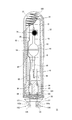
- FIG. (2) Lamp FIG. 2 is a front view of the lamp 14 according to the embodiment.
- the lamp 14 has a pair of electrodes inside, and a light emitting tube 30 that forms a discharge space, an inner tube 32 that is an airtight container for housing the light emitting tube 30, and a protection covering the inner tube 32.
- a triple tube structure including an outer tube 34 that is a container, a base 36 for receiving power from a socket of the lighting fixture 12, a positioning member 37 for preventing displacement of the inner tube 32 with respect to the outer tube 34, and the arc tube 30. It further includes a pair of power supply lines 38 and 40 for supplying electric power and supporting the arc tube 30.
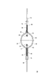
- FIG. 3 is a front sectional view of the arc tube 30.
- the arc tube 30 is composed of a main tube portion 44 having a discharge space 42 hermetically sealed therein, and thin tube portions 46 and 48 formed so as to extend on both sides of the main tube portion 44 in the tube axis direction.
- An enclosure 50 is provided.
- the main tube portion 44 and the thin tube portions 46 and 48 are made of, for example, translucent ceramic, and the arc tube 30 is also called, for example, a ceramic arc tube.
- the arc tube 30 is also called, for example, a ceramic arc tube.
- a polycrystalline alumina ceramic can be used as the translucent ceramic.
- you may comprise with another ceramic or quartz glass.
- the main pipe portions 44 are substantially opposed to each other on the central axis in the longitudinal direction of the lamp 14 (hereinafter, also simply referred to as “lamp axis”) or on an axis parallel to the lamp axis within the discharge space 42.
- lamp axis in the longitudinal direction of the lamp 14
- a pair of electrodes 52 and 54 is provided.
- the discharge space 42 is filled with a predetermined amount of metal halide, which is a luminescent material, rare gas, which is a starting auxiliary gas, and mercury, which is a buffer gas.
- metal halide for example, a mixed iodide containing sodium iodide, dysprosium iodide, or cerium iodide is used.
- the metal halide is appropriately determined according to the emission color of the lamp 14.
- the electrodes 52 and 54 include electrode rods 56 and 58, and electrode coils 60 and 62 provided at ends of the electrode rods 56 and 58 on the distal end side (discharge space 42 side).
- Molybdenum coils 64 and 66 are inserted in the gap between the electrode rods 56 and 58 and the thin tube portions 46 and 48 in a state where the molybdenum coils 64 and 66 are wound around the electrode rods 56 and 58 to prevent the light emitting material from entering the gap.
- Molybdenum coils 64 and 66 are inserted in the gap between the electrode rods 56 and 58 and the thin tube portions 46 and 48 in a state where the molybdenum coils 64 and 66 are wound around the electrode rods 56 and 58 to prevent the light emitting material from entering the gap.
- the electrodes 52 and 54 are substantially opposed to each other on the lamp axis as described above, that is, the center axes of the electrode rods 56 and 58 coincide with the lamp axis (straight). Are on the line.)
- the center axis and the lamp axis may not coincide with each other because of the accuracy of the process.
- the thin tube portions 46 and 48 have a cylindrical shape, and power feeders 68 and 70 in which the respective electrodes 52 and 54 are joined to the distal end portion (the end portion opposite to the main tube portion 44) are inserted into each of the thin tube portions 46 and 48. ing.
- the power feeding bodies 68 and 70 are sealed by seal materials 72 and 74 made of frit poured into the tip portions of the thin tube portions 46 and 48, respectively.
- the inner tube 32 has a bottomed cylindrical shape, and in addition to the arc tube 30, a pair of power supply lines that extend substantially parallel to the direction in which the tube axis of the arc tube 30 extends. 38, 40, a getter 76 for adsorbing impurities inside the inner tube 32, a proximity conductor 78 for improving the starting performance of the arc tube 30, a quartz glass tube 80 covering a part of the power supply line 38, and the like are stored. In the state, the open end is shielded.
- the open end of the inner tube 32 is pinched and pinched by pinching the pinched portions from two directions perpendicular to the tube axis and opposite to each other, with the softened end portion being shielded. It is shielded (also called crushing sealing) by a so-called pinch shield method.
- the two directions are also referred to as “pinch directions”.
- the pinch shield portion is used as a pinch seal portion (the “crush sealing portion” of the present invention) 82, and this pinch seal portion 82 has a flat flat shape, and is a pinched surface (flat surface). Is a pinch surface, the two pinch surfaces of the pinch seal portion 82 are substantially parallel to each other, and the tube axis of the inner tube 32 is located at the approximate center between the two pinch surfaces.
- the pair of power supply lines 38 and 40 are for supplying power to the arc tube 30 as described above, and are supported by the pinch seal portion 82 of the inner tube 32.
- the lengths of the pair of power supply lines 38 and 40 are different from each other.
- the longer power supply line 38 extends along the outer surface of the arc tube 30 and extends outward (outward in the direction perpendicular to the tube axis of the arc tube) at the main tube portion 44 of the arc tube 30. It is overhanging.
- This overhanging portion is referred to as an overhanging portion 84, and the portions bent to form the overhanging portion 84 are referred to as bending portions 86 and 88.
- it may replace with the bending parts 86 and 88 for comprising the overhang
- the longer power supply line 38 is connected to the power supply body 70 extending from the narrow tube portion 48 of the arc tube 30, and the shorter power supply line 40 is connected to the power supply body 68 extending from the narrow tube portion 46 of the arc tube 30.
- Each is connected. Note that the arc tube 30 is held in the inner tube 32 by this connection.
- a getter 76, a proximity conductor 78, and a quartz glass tube 80 are attached to the power supply line 38 in this order from the distal end (the end opposite to the pinch seal portion 82) side of the inner tube 32. .
- the getter 76 is fixed to the power supply line 38 so as to straddle the narrow tube portion 48 of the arc tube 30 and the power supply line 38 extending in parallel with the narrow tube portion 48.
- the thin tube portion 48 is a thin tube portion on the side away from the pinch seal portion 82 of the inner tube 32, that is, on the side close to the distal end portion of the inner tube 32.
- the getter 76 is fixed by welding, for example.
- the proximity conductor 78 is made of a strip-shaped metal plate, and an outer peripheral surface of the thin tube portion 46, which is one thin tube portion from the middle in the longitudinal direction to the one end of the metal plate, is provided along the circumferential direction.
- the thin tube portion 46 is in contact with the outer peripheral surface.
- the installation portion 92 of the proximity conductor 78 can be elastically deformed in accordance with the radial expansion of the narrow tube portion 46, and one end of the metal plate is a free end, and the expansion of the narrow tube portion 46 due to heat during lighting. Accordingly, an increase in diameter (increasing the diameter of the eaves portion 92) is allowed.
- the quartz glass tube 80 is inserted with the power supply line 38 so as to cover a space between the pinch seal portion 82 and the portion where the proximity conductor 78 is fixed in the power supply line 38.
- connection lines an “electric connection line” of the present invention
- 98 and 100 extend from the end face of the pinch seal portion 82 of the inner pipe 32, and the power supply line 38 described above. , 40 are connected to contact pins (“pin pins” of the present invention) 102, 104 of the base 36 through metal foils 94, 96 and connection lines 98, 100, respectively.
- one end of the power supply lines 38 and 40 near the base 36 is on the other end of the metal foils 94 and 96, and the connection wires 98 and 100 are near the arc tube 30. Similarly, the other end portions are connected to one end portions of the metal foils 94 and 96, respectively.
- connection lines 98 and 100 are configured by a bar member having a central axis extending in parallel with each other at a predetermined interval from the end surface of the pinch seal portion 82 while maintaining the linearity thereof. Yes.
- the extending direction of the connection lines 98 and 100 is parallel to the extending direction of the tube axis of the inner tube in the pinch seal portion 82.
- connection between the metal foils 94 and 96 and the power supply lines 38 and 40 and the connection between the metal foils 94 and 96 and the connection lines 98 and 100 are performed by, for example, welding.
- the convex part at the tip of the other end of the inner pipe 32 is a tip-off part 105 which is the remaining part of the exhaust pipe used when the inside of the inner pipe 32 is evacuated.
- the reason why the inner tube 32 is evacuated is to prevent oxidation of the power feeders 68, 70, the power supply lines 38, 40, the proximity conductor 78, and the like that are exposed to high temperatures when the lamp is lit.
- the inner tube 32 is hermetically sealed by a pinch seal portion 82 on one end side and a tip-off portion 105 on the other end side. For this reason, the inner tube 32 is also an airtight container.
- the inner tube 32 is covered with an outer tube 34 having a bottomed tubular shape (that is, a tubular shape in which one end is opened and the other end is closed).
- a bottomed tubular shape that is, a tubular shape in which one end is opened and the other end is closed.
- the positioning member 37 is for preventing the axial displacement of the inner tube 32 with respect to the outer tube 34, and is provided between the other end of the inner tube 32 and the outer tube 34.
- the positioning member 37 is made of a strand whose diameter is the distance (gap) between the outer peripheral surface on the other end side of the inner tube 32 and the inner peripheral surface on the other end side of the outer tube 34.
- This coil is configured, and this coil has a tapered shape in accordance with the shape of the other end portion of the inner tube 32.
- the outer tube 34 has a function of absorbing ultraviolet rays that are emitted from the arc tube 30 and transmitted through the inner tube 32 and that affect the human body when emitted from the lamp. Yes.
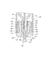
- FIG. 4 is a sectional view of one end side of the lamp.
- the inner tube 32 is inserted into the outer tube 34 while being supported by the base 36, and the base 36, the inner tube 32, and the outer tube 34 are fixed (integrated) by an adhesive 106 (for example, cement). ) That is, one end of the inner tube 32 and one end of the outer tube 34 are fixed to the base 36 through the cement 106.
- an adhesive 106 for example, cement
- FIG. 5 is a perspective view of the base.
- the base 36 is a so-called pin type, and is formed on the disk-like base portion 108 and the upper surface of the base portion 108 (the end surface on the arc tube 30 side).
- a holding portion 110 that holds the pinch seal portion 82 of the pipe 32 and a pair of contact pins 102 and 104 that extend on the lower surface of the base portion 108 are provided.
- the base portion 108 is separated from the small-diameter portion 114 on the central axis of the base 36, a large-diameter portion 112 that is the same as or larger than the outer diameter of the outer tube 34, a small-diameter portion 114 having a smaller diameter than the large-diameter portion 112. Accordingly, the inclined portion 116 having a reduced diameter is provided in this order so that the large-diameter portion 112 is located on the arc tube 30 side.
- the base portion 108 has a pair of through holes 108a and 108b at a predetermined interval. As shown in FIG. 4, the contact pins 102 and 104 (cylindrical portions 122 and 124 described later) are inserted into the through holes 108a and 108b. ) Bases 122a and 124a are inserted and fixed.
- the holding unit 110 has a pair of holding (gripping) portions 118 and 120 that grip the pinch seal portion 82 of the inner tube 32 from the pinch direction.
- the holding portions 118 and 120 protrude from the large diameter portion 112 of the base portion 108 toward the arc tube 30 side.
- the holding portions 118 and 120 are viewed from the extending direction of the holding portions 118 and 120, the holding portions 118 and 120 are as much as the thickness of the pinch seal portion 82 of the inner tube 32 (the thickness in the pinch direction).
- the side facing the inner peripheral surface of the outer tube 34 has an arc shape that matches the inner peripheral surface of the outer tube 34.
- a part of the mutually facing surfaces of the holding portions 118 and 120 serves as holding regions 118a and 120a for holding the adhesive 106 used for joining the inner tube 32.
- the holding regions 118a and 120a are configured by grooves extending in the tube axis direction of the inner tube 32 (or extending in the protruding direction of the holding portions 118 and 120).
- the holding portions 118 and 120 are viewed from the directions orthogonal to both the extending direction and the pinch direction of the holding portions 118 and 120 (in other words, virtual lines connecting the central axes of the contact pins 102 and 104) 4 when viewed from the top, and is a holding region 118b, 120b that holds the adhesive 106 used to join the outer tube 34.
- the holding regions 118b and 120b are configured by recesses formed in the bases of the holding portions 118 and 120.
- the contact pins 102 and 104 include cylindrical portions 122 and 124 and large diameter portions 126 and 128 having a larger diameter than the cylindrical portions 122 and 124.
- connection lines 98 and 100 are imaginary lines connecting the central axes of the pair of contact pins 102 and 104 in the cylindrical portions 122 and 124 of the contact pins 102 and 104 in a state where the connection lines 98 and 100 are inserted through the contact pins 102 and 104. The part located in is depressed from the outer side of the virtual line.
- connection wires 98 and 100 are electrically connected.
- FIG. 6 is a schematic diagram of a lamp assembling method according to the present embodiment.
- a base 36, an inner tube 32, and an outer tube 34 are prepared. At this time, as shown in FIG. 6, a positioning member 37 is put on the other end of the inner tube 32.
- cement as an adhesive 106 is applied to both pinch surfaces of the pinch seal portion 82 at one end of the inner tube 32 and the holding regions 118a and 120a of the holding portions 118 and 120 constituting the holding portion 110 of the base 36. .
- connection lines 98 and 100 extending from the pinch seal portion 82 of the inner tube 32 in a direction parallel to the tube axis of the inner tube 32 are inserted into the through holes 108 a and 108 b of the base portion 108 of the base 36.
- the base 36 and the inner tube 32 are relatively brought closer (“A” in the figure).
- the pinch seal portion 82 is inserted between the pair of holding portions 118 and 120, and the pair of connection lines 98 and 100 of the inner tube 32 are inserted into the contact pins 102 and 104 of the base 36.
- cement as the adhesive 106 is applied to the outer peripheral surfaces of the holding portions 118 and 120 of the base 36 and the holding regions 118b and 120b, and the inner peripheral surface of one end portion of the outer tube 34.
- the outer tube 34 is put on the inner tube 32 (“B” in FIG. 6), and the open end (end surface of one end) of the outer tube 43 is brought into contact with the base portion 108 (large diameter portion 112) of the base 36.
- the adhesive 106 is cured while maintaining this contact state. Thereby, the base 36, the inner tube 32, and the outer tube 34 are fixed, and the assembly is completed.
- the cylindrical portions 122 and 124 of the contact pins 102 and 104 are parallel to a virtual plane including the central axes of both the pair of contact pins 102 and 104 and orthogonal to the contact pins 102 and 104. Press from the direction to make it locally recessed. Thereby, the connection lines 98 and 100 are pressed and fixed by the recessed portions 102a and 104a in the contact pins 102 and 104, and the connection lines 98 and 100 are electrically connected to the contact pins 102 and 104, The lamp 14 is completed.
- FIG. 7 is a diagram for explaining the pressing direction of the contact pin.
- FIG. 7 is a view of the base 36 seen from the extending direction of the contact pins 102 and 104.
- the arrow Y in the figure is the pinch direction, and “O” is the ramp axis (also the axis of the inner tube 32 and the outer tube 34).
- the two-dot chain line is an imaginary line passing through the centers of the pair of contact pins 102 and 104, and is also a imaginary plane that is parallel to the pinch surface of the pinch seal portion 82 of the inner tube 32 and includes the lamp axis O. .
- the pressing direction according to the present embodiment is on an imaginary line passing through the centers of the pair of contact pins 102 and 104, and is adjacent to the other contact pins 104 and 102 in each contact pin 102 and 104.
- the direction orthogonal to the contact pins 102 and 104, and the directions indicated by the arrows C and D in FIG. (2) Effect In the lamp manufactured by the above assembling method, it is possible to suppress the occurrence of cracks in the pinch seal portion even when the lamp is turned on and off repeatedly. The reason for this will be described below.
- FIG. 8 is a schematic diagram for explaining a conventional assembling method, in which (a) shows a state before pressing, and (b) shows a state after pressing. 8 is an explanatory diagram and is different from FIG. 2 and the like, the same reference numerals are used for the same configuration as the embodiment, and the connection line 100 will be described.
- FIG. 8 is a diagram showing the inside of the base when pressing, and the pressing direction is a direction orthogonal to the pinch surface (a direction from the top to the bottom in the figure), and this direction is It is also a direction orthogonal to an imaginary line connecting the centers of the pair of contact pins.
- the region H (the connection line 100 is connected to the outside from the pinch seal portion 82 to the outside) where the compression load F, which is the region in contact with the connection wire 100 in the pinch seal portion 82, is directly acting. It is a region H just before the position where it extends and is a lower region of the connection line 100 in the pinch seal portion 82 in the figure, and is a hatched region in FIG. To do.
- This region H is a thin portion of the flat pinch seal portion 82. In addition to the compression load F acting on this region H, when a heat load due to lighting-off is additionally applied, this region H Cracks are generated.
- the pressing direction of the contact pin 104 is a direction parallel to the pinch surface and perpendicular to the contact pin 104. Therefore, the pair of contact pins 102, A compressive load due to pressing acts in the direction connecting 104.
- This direction is on the imaginary line X in FIG. 7, and coincides with the wide direction of the flat pinch seal portion 82 as shown in FIG. Therefore, even when a heat load due to turning on / off is additionally applied to the area subjected to the load caused by pressing, the area subjected to these loads becomes wider than before, so that the occurrence of cracks can be suppressed. is there.
- the load receiving region can be made larger than before. The occurrence of cracks can be suppressed.
- the direction in which the contact pin is pressed may be a direction parallel to (including) a virtual plane composed of (including) the central axes of the pair of contact pins (the pressing direction of the contact pin is also a direction parallel to the pinch surface).
- the dimension of the region receiving the pressing load in the pinch seal portion can be made larger than the thickness of the pinch seal portion, and the occurrence of cracks and the like can be prevented.
- the central axis of the recessed portion (which is also the direction pressed when forming the recessed portion) is within a range of ⁇ 10 degrees with respect to a virtual plane including both central axes of the pair of contact pins. Compared with the case where the direction is parallel to the virtual plane, the effect of preventing the occurrence of cracks and the like is not substantially changed.
- the central axis (pressed direction) of the recessed portion can be obtained by connecting the centers of at least two arbitrary cross sections in the recessed depth direction in the recessed portion.
- the shape of the recessed portion is rotationally symmetric.
- it is regarded as a shape (a shape obtained by turning an arbitrary straight line / curve around the rotation center once), it can be obtained as a straight line connecting the centers of two arbitrary cross sections in the indentation depth direction.
- this straight line, that is, the central axis of the recessed portion can be obtained from the shape of the recessed portion formed after pressing.
- the central axis of the recessed portion is not limited to the above method.
- the direction in which the size of the opening area of the recessed portion is maximized Can be regarded as the direction.
- the shape of the recessed portion is regarded as a rotationally symmetric shape
- the size of the recessed portion (opening area) is the largest when the recessed portion is viewed from above the rotation center, and from the rotation center.
- the size of the recessed portion is smaller than the size of the recessed portion when viewed from the center of rotation, and the direction in which the size of the recessed portion is maximized is pressed. Matches the direction. 3.
- Example An example of the lamp according to the above embodiment will be described below.
- An example of the lamp 14 described here has a power consumption of 70 (W), and the total length of the lamp 14 is approximately 90 (mm) to 120 (mm) (varies slightly depending on the cap 36 used).
- the arc tube 30 has an outer diameter of a main tube portion 44 of 9.7 (mm) and a thickness of 0.6 (mm).
- the outer diameters of the thin tube portions 46 and 48 are 2.63 (mm) and the thickness is 0.9 (mm).
- the main pipe portion 44 and the thin tube portions 46 and 48 are made of polycrystalline alumina ceramic.
- the envelope 50 includes two molded products in which the half of the main pipe portion (44) and the thin pipe portions 46 and 48 are integrally formed, for example, the portions where the half of the main pipe portion (44) abut each other. Are obtained by joining and sintering with paste-like alumina and integrating them.
- the electrodes 52 and 54 are made of a molybdenum material wire as the electrode coils 60 and 62, and the outer diameter of the coil is 0.70 (mm).
- a tungsten material having a diameter of 0.35 (mm) is used.
- the proximity conductor 78 is a thin plate made of molybdenum having a thickness of 0.1 (mm), and the width of the proximity conductor 78 (the dimension in the short direction of the metal plate) is 3.0 (mm) and long. The length (the dimension in the longitudinal direction of the metal plate) is 4.2 (mm).
- the power supply wires 38 and 40 are made of molybdenum strands having a diameter of 0.6 (mm).
- the connecting wires 98 and 100 are made of a bar material made of molybdenum material (the cross-sectional shape is circular), and its outer diameter is 1.0 (mm).
- the outer diameter (thickness) of the connecting wires 98 and 100 is 0.5 (mm) or more, and the thickness of the pinch seal portion 82 (thickness in the pinch direction) is 2.5 (mm) or more and 5.0 (mm).
- the problems described in the section “Problems to be solved by the invention” occur in the following cases.
- the connecting wires 98 and 100 are often used with an outer diameter of 1.0 (mm) or less.
- the inner tube 32 has an outer diameter of 15.5 (mm) and a thickness of 1.25 (mm), and quartz glass is used.
- the outer tube 34 has an outer diameter of 20.5 (mm) and a thickness of 1.3 (mm), and hard glass is used.
- ⁇ Modification> Although the present invention has been described based on the above embodiment, the content of the present invention is not limited to the specific examples shown in the above embodiment. For example, the following modifications are possible. Can be implemented. 1. In the embodiment, as shown in FIG. 2, a so-called pin type is used as the base 36, but other types of bases may be used. Examples of other types include G type and PG type. That is, it is sufficient if the base is provided with a contact pin in the extending direction in which the electrical connection line extends from the pinch seal portion, and the electrical connection line is fixed to a locally recessed portion of the contact pin. 2.
- the envelope 50 constituting the arc tube 30 in the embodiment is obtained by integrating two molded products in which a half of the main tube portion (44) and the thin tube portions 46 and 48 are integrally molded.
- the envelope according to the present invention is not limited to the envelope according to the embodiment.
- the main tube portion and the thin tube portion may be formed separately and then integrated by shrink fitting. Furthermore, they are not formed separately from the main tube portion and the thin tube portion, but are formed integrally. Alternatively, it may be composed of a single structure.
- the envelope has a cylindrical member (specifically, a cylindrical member), a ring member integrated by shrink fitting on both ends of the cylindrical member, and one end portion in the central through hole of the ring member. You may comprise from the thin tube member integrated by shrink fitting.
- the envelope in this case is a so-called cylindrical type. 3.
- Inner tube / outer tube In the embodiment, the lamp has a triple tube structure including an arc tube, an inner tube, and an outer tube, but a lamp having a double tube structure including an arc tube and an outer tube is used. May be.
- the inner tube was a single seal with the other end sealed, it may be configured with a double seal with both ends sealed. 4).
- the power consumption is 70 (W).
- the present invention is not limited to this value, and can be implemented as long as the power consumption is in the range of 20 W to 250 W.
- a metal halide lamp has been described as an example.
- the invention can be applied.
- Such lamps include halogen bulbs equipped with caps such as G type, GY type, and GX type.
- the present invention can be used for a lamp having a cap pin in which a connection line extending from a pinch seal portion extends in the same direction.
Landscapes
- Vessels And Coating Films For Discharge Lamps (AREA)
- Common Detailed Techniques For Electron Tubes Or Discharge Tubes (AREA)
Abstract
Description
1.構成
(1)照明装置
図1は、本実施の形態に係るメタルハライドランプを備える照明装置10の全体図であり、照明器具12の内部が分かるように一部を切り欠いている。
(2)ランプ
図2は、実施の形態に係るランプ14の正面図である。
2.組立て方法
(1)方法
メタルハライドランプ14の組立て方法、特に、内管32、外管34、口金36の組立てについて説明する。
(2)効果
上記組立て方法で製造したランプにおいては、点灯-消灯を繰り返してもピンチシール部にクラックが発生するのを抑制することができる。この理由について以下説明する。
3.実施例
上記実施の形態に係るランプの実施例について以下説明する。
ここでの外囲器50は、本管部(44)の半分と細管部46,48とが一体成形された2つの成形品を、例えば、本管部(44)の半分の突き合わさる部分同士をペースト状のアルミナで接合し焼結させて一体化することで得ている。
以上、本発明を上記実施の形態に基づいて説明したが、本発明の内容が、上記実施の形態に示された具体例に限定されないことは勿論であり、例えば、以下のような変形例を実施することができる。
1.口金
実施の形態では、口金36として、図2に示すように、所謂ピンタイプを利用したが、他のタイプの口金を使用しても良い。他のタイプとしては、例えば、Gタイプ、PG形等がある。つまり、電気接続線がピンチシール部から延出している延出方向にコンタクトピンを備え、当該電気接続線がコンタクトピンの局所的な凹入部分に固定されるような口金であれば良い。
2.発光管
実施の形態における発光管30を構成する外囲器50は、本管部(44)の半分と細管部46,48とが一体成形された2つの成形品を一体化したものであるが、本発明に係る外囲器は、実施の形態に係る外囲器に限定されるものではない。
3.内管・外管
実施の形態では、ランプは、発光管、内管、外管を備えた三重管構造のものを用いたが、発光管と外管とからなる二重管構造のものを用いても良い。
4.ランプ
実施の形態では、消費電力が70(W)であったが、本発明はこの数値に限定するものではなく、消費電力が20W~250Wの範囲内であれば実施できる。
32 内管
34 外管
36 口金
82 ピンチシール部
98,100 接続線
102,104 コンタクトピン
102a,104a 凹入部分
Claims (6)
- 端部に圧潰封止部を有するガラス管と、前記ガラス管の端部に装着された口金とを有するランプであって、
前記圧潰封止部からは一対の電気接続線が延出し、
前記口金は前記電気接続線の延出方向に延出する一対の筒状をした口金ピンを備え、
前記電気接続線は、前記口金ピン内に挿通された状態で前記口金ピンの筒部側面が凹入されることで、前記口金ピンに固定され、
前記口金ピンの凹入部分の押圧方向は、前記一対の口金ピンの両方の中心軸を含む仮想平面に対して±10度の範囲内にある
ことを特徴とするランプ。 - 前記口金ピンの凹入部分は、前記筒部側面が局所的に凹入されたものであり、
前記口金ピンの凹入部分の押圧方向は、前記一対の口金ピンの両方の中心軸を含む仮想平面に対して平行である
ことを特徴とする請求項1に記載のランプ。 - 前記ガラス管は一対の電極を有する発光管を格納し、
前記電気接続線は前記電極に電気的に接続されている
ことを特徴とする請求項1に記載のランプ。 - 前記ガラス管は一対の電極を有する発光管を格納し、
前記電気接続線は前記電極に電気的に接続されている
ことを特徴とする請求項2に記載のランプ。 - 前記電気接続線は、モリブデン棒であり、
前記圧潰封止部の厚みが2.5mm以上5.0mm以下の範囲である
ことを特徴とする請求項3に記載のランプ。 - 前記ランプはメタルハライドランプである
ことを特徴とする請求項5に記載のランプ。
Priority Applications (4)
| Application Number | Priority Date | Filing Date | Title |
|---|---|---|---|
| US13/144,466 US8558457B2 (en) | 2010-03-03 | 2011-01-21 | Lamp comprising glass tube having pinched sealed portion at end |
| EP11730168.9A EP2544213B1 (en) | 2010-03-03 | 2011-01-21 | Lamp |
| CN2011800010900A CN102318029A (zh) | 2010-03-03 | 2011-01-21 | 灯 |
| KR1020117016926A KR20130044122A (ko) | 2010-03-03 | 2011-01-21 | 램프 |
Applications Claiming Priority (2)
| Application Number | Priority Date | Filing Date | Title |
|---|---|---|---|
| JP2010-046798 | 2010-03-03 | ||
| JP2010046798A JP2011181450A (ja) | 2010-03-03 | 2010-03-03 | ランプ |
Publications (1)
| Publication Number | Publication Date |
|---|---|
| WO2011108184A1 true WO2011108184A1 (ja) | 2011-09-09 |
Family
ID=44541855
Family Applications (1)
| Application Number | Title | Priority Date | Filing Date |
|---|---|---|---|
| PCT/JP2011/000316 Ceased WO2011108184A1 (ja) | 2010-03-03 | 2011-01-21 | ランプ |
Country Status (6)
| Country | Link |
|---|---|
| US (1) | US8558457B2 (ja) |
| EP (1) | EP2544213B1 (ja) |
| JP (1) | JP2011181450A (ja) |
| KR (1) | KR20130044122A (ja) |
| CN (1) | CN102318029A (ja) |
| WO (1) | WO2011108184A1 (ja) |
Families Citing this family (4)
| Publication number | Priority date | Publication date | Assignee | Title |
|---|---|---|---|---|
| JP5762933B2 (ja) * | 2011-11-18 | 2015-08-12 | 三菱電機照明株式会社 | 電球類の口金 |
| JP2016076383A (ja) * | 2014-10-07 | 2016-05-12 | 岩崎電気株式会社 | 片口金ランプの製造方法及び片口金ランプ |
| JP6045643B2 (ja) * | 2015-06-10 | 2016-12-14 | 三菱電機照明株式会社 | 照明用光源の口金 |
| EP3845508A4 (en) * | 2018-08-30 | 2022-05-04 | Kyocera Corporation | CERAMIC STRUCTURE |
Citations (7)
| Publication number | Priority date | Publication date | Assignee | Title |
|---|---|---|---|---|
| JPH0186064U (ja) * | 1987-11-28 | 1989-06-07 | ||
| JPH08102249A (ja) * | 1994-09-30 | 1996-04-16 | Toshiba Lighting & Technol Corp | ランプおよび照明装置 |
| JPH11508402A (ja) * | 1996-04-19 | 1999-07-21 | パテント−トロイハント−ゲゼルシヤフト フユア エレクトリツシエ グリユーランペン ミツト ベシユレンクテル ハフツング | 反射形ランプ |
| JP2003524871A (ja) * | 2000-02-24 | 2003-08-19 | コーニンクレッカ フィリップス エレクトロニクス エヌ ヴィ | キャップ付電灯および低圧水銀蒸気放電灯 |
| JP2006331932A (ja) * | 2005-05-27 | 2006-12-07 | Ssec Kk | メタルハライドランプ |
| JP2007504627A (ja) | 2003-09-05 | 2007-03-01 | コニンクリユケ フィリップス エレクトロニクス エヌ.ブイ. | 照明ユニット、ホルダ、ランプ及び照明器具 |
| JP2007080678A (ja) | 2005-09-14 | 2007-03-29 | Matsushita Electric Ind Co Ltd | 金属蒸気放電ランプ、ランプソケット、および照明装置 |
Family Cites Families (3)
| Publication number | Priority date | Publication date | Assignee | Title |
|---|---|---|---|---|
| US4622346A (en) | 1985-11-29 | 1986-11-11 | Atlantic Richfield Company | Process for producing modified styrenic polymer beads for high strength foamed articles |
| DE4008375A1 (de) * | 1990-03-15 | 1991-09-19 | Patent Treuhand Ges Fuer Elektrische Gluehlampen Mbh | Hochdruckentladungslampe |
| DE4233469A1 (de) * | 1992-10-05 | 1994-04-07 | Patent Treuhand Ges Fuer Elektrische Gluehlampen Mbh | Verfahren zur Herstellung einer einseitig gequetschten Hochdruckentladungslampe kleiner Leistung und Hochdruckentladungslampen |
-
2010
- 2010-03-03 JP JP2010046798A patent/JP2011181450A/ja not_active Withdrawn
-
2011
- 2011-01-21 US US13/144,466 patent/US8558457B2/en not_active Expired - Fee Related
- 2011-01-21 EP EP11730168.9A patent/EP2544213B1/en not_active Not-in-force
- 2011-01-21 WO PCT/JP2011/000316 patent/WO2011108184A1/ja not_active Ceased
- 2011-01-21 KR KR1020117016926A patent/KR20130044122A/ko not_active Withdrawn
- 2011-01-21 CN CN2011800010900A patent/CN102318029A/zh active Pending
Patent Citations (7)
| Publication number | Priority date | Publication date | Assignee | Title |
|---|---|---|---|---|
| JPH0186064U (ja) * | 1987-11-28 | 1989-06-07 | ||
| JPH08102249A (ja) * | 1994-09-30 | 1996-04-16 | Toshiba Lighting & Technol Corp | ランプおよび照明装置 |
| JPH11508402A (ja) * | 1996-04-19 | 1999-07-21 | パテント−トロイハント−ゲゼルシヤフト フユア エレクトリツシエ グリユーランペン ミツト ベシユレンクテル ハフツング | 反射形ランプ |
| JP2003524871A (ja) * | 2000-02-24 | 2003-08-19 | コーニンクレッカ フィリップス エレクトロニクス エヌ ヴィ | キャップ付電灯および低圧水銀蒸気放電灯 |
| JP2007504627A (ja) | 2003-09-05 | 2007-03-01 | コニンクリユケ フィリップス エレクトロニクス エヌ.ブイ. | 照明ユニット、ホルダ、ランプ及び照明器具 |
| JP2006331932A (ja) * | 2005-05-27 | 2006-12-07 | Ssec Kk | メタルハライドランプ |
| JP2007080678A (ja) | 2005-09-14 | 2007-03-29 | Matsushita Electric Ind Co Ltd | 金属蒸気放電ランプ、ランプソケット、および照明装置 |
Non-Patent Citations (1)
| Title |
|---|
| See also references of EP2544213A4 |
Also Published As
| Publication number | Publication date |
|---|---|
| EP2544213B1 (en) | 2014-09-17 |
| KR20130044122A (ko) | 2013-05-02 |
| EP2544213A4 (en) | 2013-09-11 |
| US8558457B2 (en) | 2013-10-15 |
| CN102318029A (zh) | 2012-01-11 |
| EP2544213A1 (en) | 2013-01-09 |
| JP2011181450A (ja) | 2011-09-15 |
| US20120187829A1 (en) | 2012-07-26 |
Similar Documents
| Publication | Publication Date | Title |
|---|---|---|
| JP4130842B2 (ja) | 金属蒸気放電ランプ及び照明装置 | |
| US7990035B2 (en) | Metal vapor discharge lamp with a restrain member for inner tube | |
| JP2011181450A (ja) | ランプ | |
| CN102473584B (zh) | 高亮度放电灯 | |
| JP3816465B2 (ja) | 蛍光ランプ | |
| CN101248510B (zh) | 金属蒸汽放电灯以及具有该金属蒸汽放电灯的照明装置 | |
| JP5026973B2 (ja) | ランプ | |
| JP4396577B2 (ja) | 金属蒸気放電ランプ、およびそれを用いた照明装置 | |
| JP5134054B2 (ja) | 金属蒸気放電ランプおよび照明装置 | |
| JP3124181U (ja) | 高圧放電ランプ | |
| JP4569928B2 (ja) | 金属蒸気放電ランプおよび照明装置 | |
| JP2007273373A (ja) | メタルハライドランプおよび照明装置 | |
| JP2007080678A (ja) | 金属蒸気放電ランプ、ランプソケット、および照明装置 | |
| JP2007273333A (ja) | 蛍光ランプ | |
| JPH06150889A (ja) | 管 球 | |
| JP2012048879A (ja) | 金属蒸気放電ランプ | |
| JP2012048878A (ja) | 金属蒸気放電ランプ | |
| US20080238322A1 (en) | Structural unit for an electric lamp with an outer bulb | |
| JP2011181437A (ja) | 放電ランプ、および当該放電ランプを有する照明装置 | |
| JP2005190742A (ja) | 金属蒸気放電ランプ及び照明装置 | |
| US20040245901A1 (en) | High intensity discharge headlight structure | |
| JPH0388254A (ja) | セラミック放電灯 |
Legal Events
| Date | Code | Title | Description |
|---|---|---|---|
| WWE | Wipo information: entry into national phase |
Ref document number: 201180001090.0 Country of ref document: CN |
|
| WWE | Wipo information: entry into national phase |
Ref document number: 13144466 Country of ref document: US |
|
| WWE | Wipo information: entry into national phase |
Ref document number: 2011730168 Country of ref document: EP |
|
| ENP | Entry into the national phase |
Ref document number: 20117016926 Country of ref document: KR Kind code of ref document: A |
|
| 121 | Ep: the epo has been informed by wipo that ep was designated in this application |
Ref document number: 11730168 Country of ref document: EP Kind code of ref document: A1 |
|
| NENP | Non-entry into the national phase |
Ref country code: DE |