WO2011108398A1 - 電動パワーステアリング装置 - Google Patents
電動パワーステアリング装置 Download PDFInfo
- Publication number
- WO2011108398A1 WO2011108398A1 PCT/JP2011/053815 JP2011053815W WO2011108398A1 WO 2011108398 A1 WO2011108398 A1 WO 2011108398A1 JP 2011053815 W JP2011053815 W JP 2011053815W WO 2011108398 A1 WO2011108398 A1 WO 2011108398A1
- Authority
- WO
- WIPO (PCT)
- Prior art keywords
- steering
- shaft
- steering column
- electric power
- side plates
- Prior art date
- Legal status (The legal status is an assumption and is not a legal conclusion. Google has not performed a legal analysis and makes no representation as to the accuracy of the status listed.)
- Ceased
Links
Images


Classifications
-
- B—PERFORMING OPERATIONS; TRANSPORTING
- B62—LAND VEHICLES FOR TRAVELLING OTHERWISE THAN ON RAILS
- B62D—MOTOR VEHICLES; TRAILERS
- B62D1/00—Steering controls, i.e. means for initiating a change of direction of the vehicle
- B62D1/02—Steering controls, i.e. means for initiating a change of direction of the vehicle vehicle-mounted
- B62D1/16—Steering columns
- B62D1/18—Steering columns yieldable or adjustable, e.g. tiltable
- B62D1/187—Steering columns yieldable or adjustable, e.g. tiltable with tilt adjustment; with tilt and axial adjustment
- B62D1/189—Steering columns yieldable or adjustable, e.g. tiltable with tilt adjustment; with tilt and axial adjustment the entire column being tiltable as a unit
-
- B—PERFORMING OPERATIONS; TRANSPORTING
- B62—LAND VEHICLES FOR TRAVELLING OTHERWISE THAN ON RAILS
- B62D—MOTOR VEHICLES; TRAILERS
- B62D1/00—Steering controls, i.e. means for initiating a change of direction of the vehicle
- B62D1/02—Steering controls, i.e. means for initiating a change of direction of the vehicle vehicle-mounted
- B62D1/16—Steering columns
- B62D1/18—Steering columns yieldable or adjustable, e.g. tiltable
- B62D1/183—Steering columns yieldable or adjustable, e.g. tiltable adjustable between in-use and out-of-use positions, e.g. to improve access
-
- B—PERFORMING OPERATIONS; TRANSPORTING
- B62—LAND VEHICLES FOR TRAVELLING OTHERWISE THAN ON RAILS
- B62D—MOTOR VEHICLES; TRAILERS
- B62D1/00—Steering controls, i.e. means for initiating a change of direction of the vehicle
- B62D1/02—Steering controls, i.e. means for initiating a change of direction of the vehicle vehicle-mounted
- B62D1/16—Steering columns
- B62D1/18—Steering columns yieldable or adjustable, e.g. tiltable
- B62D1/184—Mechanisms for locking columns at selected positions
-
- B—PERFORMING OPERATIONS; TRANSPORTING
- B62—LAND VEHICLES FOR TRAVELLING OTHERWISE THAN ON RAILS
- B62D—MOTOR VEHICLES; TRAILERS
- B62D1/00—Steering controls, i.e. means for initiating a change of direction of the vehicle
- B62D1/02—Steering controls, i.e. means for initiating a change of direction of the vehicle vehicle-mounted
- B62D1/16—Steering columns
- B62D1/18—Steering columns yieldable or adjustable, e.g. tiltable
- B62D1/187—Steering columns yieldable or adjustable, e.g. tiltable with tilt adjustment; with tilt and axial adjustment
-
- B—PERFORMING OPERATIONS; TRANSPORTING
- B62—LAND VEHICLES FOR TRAVELLING OTHERWISE THAN ON RAILS
- B62D—MOTOR VEHICLES; TRAILERS
- B62D3/00—Steering gears
- B62D3/02—Steering gears mechanical
Definitions
- the present invention relates to an electric power steering apparatus.
- a tilt steering device has been proposed in which the lower portion of a steering column is supported so as to be pivotable about a tilt central axis (see, for example, Patent Document 1).
- a steering column is supported by an upper fixing bracket and a lower fixing bracket fixed to a vehicle body.
- the lower fixing bracket pivotally supports the lower column bracket fixed to the lower portion of the steering column via a tilt center axis.
- the upper fixing bracket supports the upper column bracket fixed to the upper portion of the steering column so as to be vertically slidable at the time of tilt adjustment. Further, the position of the steering column after tilt adjustment is locked by tightening the both side plates of the upper column bracket from the outside between the side plates of the upper fixed bracket by the operation of the turning lever.
- An object of the present invention is to provide a lightweight electric power steering device that is easy to assemble into a vehicle.
- a steering column (15) rotatably supporting a steering shaft and pivoted around a tilt pivot (27) at the time of tilt adjustment;
- an electric power steering apparatus (1) comprising: a fixed bracket (13) for supporting the steering column, and an electric motor (19) for steering assistance supported by the steering column (3).
- the fixed bracket includes a pair of side plates (34, 35) opposed to each other with the steering shaft in the vehicle width direction (W1), and a connecting member (36) connecting the pair of side plates.
- a first restricting portion (46) capable of restricting the rotation of the steering column in a first rotation direction (Z1) around the tilt support shaft is provided on any one of the pair of side plates.
- a second restricting portion (49) capable of restricting the rotation of the steering column in a second rotation direction (Z2) opposite to the first rotation direction is provided on the other of the pair of side plates.
- the first regulation portion and the second regulation portion can regulate relative rotation of the fixing bracket and the steering column at an excessively large angle in the tilt direction. . Therefore, the assembly to the vehicle body becomes easy.
- the fixing bracket since the fixing bracket has a simple structure in which the pair of side plates are connected by the connecting member, it can contribute to weight reduction.
- any one of the first restricting portion and the second restricting portion is a hooking engaging portion (46) which can be hooked and engaged with the first protrusion (47) extended from the steering column.
- the other may be an abutting portion (49) that can abut on the second protrusion (48) extended from the steering column from above.
- the first restricting portion is the hooking engagement portion, and the inner side surface (34a) of the side plate (34) having the hooking engagement portion is disposed in proximity to the side portion of the electric motor, and the vehicle width With respect to the direction, the distance (L1) between the side plate (34) having the hooking engagement portion and the central axis (C1) of the steering shaft is the side plate (35) having the abutting portion and the central axis of the steering shaft It may be longer than the distance (L2) with the
- the side plate having the hooking engagement portion mainly receives the load of the relatively heavy electric motor through the hooking engagement portion, so that the assembly of the electric power steering apparatus to the vehicle body is easier. become. Further, since the distance between the side plate having the hooking engagement portion and the steering shaft is relatively long, the left-right weight balance is improved. As a result, the assemblability of the electric power steering apparatus to the vehicle body is further improved. Further, since the side plate having the hooking engagement portion is close to the electric motor, it is preferable also in receiving the reaction force of the assist by the electric motor.
- the second restricting portion is the contact portion, and the inner surface (35a) of the side plate (35) having the contact portion supports the controller (20) for driving and controlling the electric motor.
- the electric motor and the controller are disposed between the pair of side plates of the fixed bracket, the electric motor and the controller can be reliably protected at the time of transportation or assembly of the vehicle.
- the heat of the controller can be dissipated to the vehicle body via the fixing bracket, and the heat radiation effect is high.
- the controller is fixed not to the steering column or the electric motor as in the prior art, but to a fixed bracket fixed to the vehicle body. Therefore, the vibration of the controller is reduced, and as a result, the durability can be improved.
- reinforcement beads (51, 52) are provided on each of the pair of side plates, and the reinforcement beads are provided with a first portion (511, 521) extending in a direction parallel to the axial direction of the steering shaft; It may be in the form of a bend including a second portion (512, 522) extending obliquely from the portion.
- first portion 511, 521
- second portion 512, 522
- first fixing bracket as the fixing bracket
- second fixing bracket which supports the steering column so as to be position adjustable at the time of tilt adjustment
- the second fixing bracket is the first fixing bracket.
- first fixing bracket and the second fixing bracket are separated from each other and are independent of each other, significant weight reduction can be achieved as compared with the case where they are integrally formed.
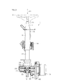
- FIG. 1 is a schematic perspective view of an electric power steering apparatus according to an embodiment of the present invention. It is a partially broken side view of an electric power steering device. It is a perspective view from another angle of an electric power steering device. It is the schematic which looked at an electric-power-steering apparatus from the axial direction lower direction of a steering shaft.
- FIG. 1 is a schematic perspective view of an electric power steering apparatus according to an embodiment of the present invention.
- the electric power steering apparatus 1 includes a steering shaft 3 coupled to a steering member 2 such as a steering wheel, an intermediate shaft 5 coupled to the steering shaft 3 via a universal joint 4, and an intermediate shaft A pinion shaft 7 is connected to the shaft 5 via a universal joint 6 and a rack shaft 8 as a steered shaft having a rack 8a engaged with a pinion 7a provided near an end of the pinion shaft 7.
- a steering mechanism A1 is configured by a rack and pinion mechanism including the pinion shaft 7 and the rack shaft 8.
- the rack shaft 8 is movably supported in the vehicle width direction W1 by a housing (not shown) fixed to the vehicle body.
- Each end of the rack shaft 8 is connected to a corresponding steered wheel 10 via a corresponding tie rod 9 and a corresponding knuckle arm (not shown).
- the steering shaft 3 has a first shaft 11 and a second shaft 12 coupled to be able to transmit torque via a torsion bar (not shown) and to be relatively movable in the axial direction X1.
- the steering shaft 3 is rotatably supported via a bearing (not shown) by a lower fixing bracket 13 as a first bracket and a steering column 15 fixed to an upper fixing bracket 14 as a second bracket.
- the lower fixing bracket 13 as the first bracket and the upper fixing bracket 14 as the second bracket are made of, for example, sheet metal and fixed to the vehicle body.
- the steering column 15 includes an upper tube 16 and a lower tube 17 fitted so as to be relatively movable in the axial direction, and a housing 18 connected to an axial lower end of the lower tube 17. Above the housing 18, an electric motor 19 for steering assistance and a controller 20 (specifically, an electronic control unit ECU: Electronic Control Unit) for controlling the operation of the electric motor 19 are arranged in the vehicle width direction W1. It is arranged by.
- ECU Electronic Control Unit
- a reduction mechanism 21 for decelerating the power of the electric motor 19 and transmitting it to the second shaft 12 is accommodated in the housing 18.
- the reduction mechanism 21 includes a drive gear (not shown) provided rotatably along with the rotation shaft of the electric motor 19 and a driven gear 22 engaged with the drive gear and coupled with the second shaft 12 rotatably.
- a worm may be used as the drive gear
- a worm wheel may be used as the driven gear 22.
- the drive gear is accommodated in a drive gear accommodating portion 23 provided in the housing 18 as shown in FIG. 1, and the driven gear 22 is in a driven gear accommodating portion 24 provided in the housing 18 as shown in FIG. It is housed. Further, the housing 18 accommodates a torque sensor 25 for detecting a steering torque applied to the steering shaft 3.
- the controller 20 accommodates a power board and a control board (not shown) in the case 26.
- the controller 20 drives and controls the electric motor 19 based on the torque detection result by the torque sensor and the vehicle speed detection result from the vehicle speed sensor (not shown).
- the electric power steering apparatus 1 is configured as a tilt steering apparatus having a tilt adjustment function.
- the lower fixing bracket 13 as a first fixing bracket fixed to the vehicle body supports the steering column 15 so as to be able to pivot around the tilt support shaft 27 via the tilt support shaft 27 consisting of a pivot shaft. doing.
- the electric motor 19 and the controller 20 are arranged to rise upward in a direction orthogonal to both the axial direction X1 of the steering shaft 3 and the central axis 27a of the tilt support shaft 27.
- the upper fixed bracket 14 as a second fixed bracket fixed to the vehicle body supports the downward grooved upper column bracket 28 fixed to the steering column 15 up and down (specifically, tilt support) when adjusting the tilt. It supports so that it can slide in the rotation direction centering on the axis
- the upper fixing bracket 14 includes an upper plate 142 having a pair of left and right mounting seats 141, and a pair of side plates 29 included in a downward groove formed on the lower surface of the upper plate 142.
- Each mounting seat 141 is provided with a mounting groove 143 that opens toward the rear of the vehicle.
- a fixing bolt (not shown) to the vehicle body is inserted upward.
- the fixing bolt is fixed to the vehicle body by inserting a so-called capsule for holding the mounting seat 141 on the vehicle body with a predetermined holding force. By the function of the capsule, the fixing bolt can be detached from the mounting groove 143 at the time of shock absorption.
- a tightening mechanism 31 is provided between the pair of side plates 29 of the upper fixed bracket 14 as the second fixed bracket for clamping and fixing the pair of side plates 30 of the upper column bracket 28.
- the tightening and the release of the tightening by the tightening mechanism 31 are performed by pivoting the operation lever 33 around the tightening shaft 32 passing through the side plates 29 of the upper fixing bracket 14 and the side plates 30 of the upper column bracket 28.
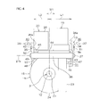
- FIG. 3 which is a perspective view of the electric power steering apparatus 1 viewed from another angle from FIG. 1 and FIG. 4 which is a bottom view of the electric power steering apparatus 1 with respect to the axial direction X1 of the steering shaft 3
- the lower fixing bracket 13 as a first fixing bracket has a pair of side plates 34 and 35 and a connecting member 36.
- the pair of side plates 34, 35 sandwich the steering shaft 3, and more specifically, opposes the housing 18 of the steering column 15 in the vehicle width direction W1.
- the connecting member 36 is positioned between the pair of side plates 34 and 35 above or below the second shaft 12 of the steering shaft 3 (in the present embodiment, above the second shaft 12 of the steering shaft 3 as shown in FIG. 1). It is connected across.
- the side plates 34 and 35 are provided with reinforcing beads 51 and 52 formed to expand outward, for example.
- the reinforcing bead 51 formed on the side plate 34 has a first portion 511 extending in a direction parallel to the axial direction X1 of the steering shaft 3 and a second portion 512 extending obliquely from the first portion 511, and has a bent shape I am
- the reinforcing bead 52 formed on the side plate 35 has a first portion 521 extending in a direction parallel to the axial direction X1 of the steering shaft 3 and a second portion 522 extending obliquely from the first portion 521. , Has a bent shape.
- Attaching plates 37 and 38 to the vehicle body extend outward from the upper ends of the pair of side plates 34 and 35, respectively.
- mounting grooves 39, 40 opened toward the front of the vehicle are formed in the mounting plates 37, 38.
- the lower fixing bracket 13 is fixed to the vehicle body by a fixing bolt (not shown) passing through the mounting grooves 39 and 40.
- the mounting grooves 39 and 40 make it possible, for example, to introduce a fixing bolt fixed on the vehicle body side in a direction perpendicular to the axis of the fixing bolt, and the assembling ability of the electric power steering device 1 to the vehicle body is good. I assume.
- the tilt support shaft 27 is inserted through the lower portions 41 and 42 of the side plates 34 and 35.
- insertion holes through which the tilt support shafts 27 are inserted are formed in the lower portions 41 and 42 of the side plates 34 and 35.
- the tilt support shaft 27 inserted into the insertion hole is inserted into an insertion hole (not shown) of the tilt support shaft connecting portion 43 provided in the housing 18 as shown in FIG.
- the housing 18 is supported swingably around the tilt support shaft 27 by the lower fixing bracket 13.
- one side plate 34 is in close proximity to the side 19 a of the electric motor 19, and the other side plate 35 is along the case 26 of the controller 20. Further, in the vehicle width direction W1, the distance L1 between one side plate 34 and the central axis C1 of the steering shaft 3 is longer than the distance L2 between the other side plate 35 and the central axis C1 of the steering shaft 3 (L1 > L2).
- the electric motor 19 is fixed to a pedestal 44 formed on the top of the housing 18.
- the case 26 of the controller 20 is fixed to the inner side surface 35 a of the other side plate 35.
- a gap 45 is formed between the case 26 and the pedestal 44.
- a hooking engagement portion 46 as a first restricting portion is provided so as to extend from the lower end of the side plate 34 close to the electric motor 19 into an angle shape (hook shape) to the other side plate 35 side.
- the hooking engagement portion 46 is opposed to the first protrusion 47 extended from the drive gear accommodation portion 23 of the housing 18 with a predetermined gap S1 therebetween.
- the hooking engagement portion 46 as the first restricting portion can be hooked and engaged with the first protrusion 47 from below when the electric power steering apparatus 1 is assembled to a vehicle.
- the hooking engagement portion 46 is hooked and engaged with the first projection 47, whereby the rotation of the steering column 15 in the first rotation direction Z1 (see FIG. 3) around the tilt support shaft 27 is restricted.
- a contact portion 49 as a second restricting portion that can contact from above with the second projection 48 extended from the driven gear accommodating portion 24 of the housing 18. Is provided.
- the contact portion 49 as the second restricting portion contacts the second projection 48 from the upper side, thereby causing a second rotation direction opposite to the first rotation direction Z1.
- the rotation of the steering column 15 about the tilt support shaft 27 to Z2 is restricted.
- the hooking engagement portion 46 as the first regulation portion and the abutment portion 49 as the second regulation portion move the swing range of the steering column 15 around the tilt support shaft 27.
- the range to be restricted is made wider than the swing range of the steering column 15 by tilt adjustment after the electric power steering apparatus 1 is assembled to the vehicle. Therefore, after the electric power steering apparatus 1 is assembled to the vehicle body, the hooking engagement portion 46 and the abutment portion 49 do not disturb the tilt adjustment.
- the assembly work to the vehicle becomes easy.
- the assembling operation of the electric power steering apparatus 1 is as follows. That is, the upper end of the intermediate shaft 5 whose lower end is connected to the pinion shaft 7 of the steering mechanism A1 is positioned in the vehicle compartment with a dash panel (not shown) penetrating therethrough. Next, the steering column 15 supporting the steering shaft 3 is assembled to the vehicle body, and then the lower end of the steering shaft 3 is inserted into the universal joint 4 at the upper end of the intermediate shaft 5 and fastened by bolts (not shown) Do.
- the lower fixing bracket 13 When the steering column 15 is assembled to the vehicle body, the lower fixing bracket 13 is assembled by inserting the bolt temporarily fixed to the vehicle body from the open side of the mounting grooves 39 and 40 of the lower fixing bracket 13. At the time of this assembly, in a state where the steering column 15 is supported by hand, the swing range of the lower fixing bracket 13 around the tilt support shaft 27 is the hooking engagement portion 46 as a first regulation portion and the second regulation portion It is regulated by the contact part 49 as. Therefore, the lower fixing bracket 13 can be easily positioned and attached to the mounting portion on the vehicle body side, and the assemblability is good.
- the lower fixing bracket 13 as the first fixing bracket has a simple structure in which the pair of side plates 34 and 35 are connected by the connecting member 36, it can contribute to the weight reduction of the electric power steering apparatus 1.
- the inner side surface 34a of the side plate 34 having the hooking engagement portion 46 is close to the side portion 19a of the electric motor 19, and the central axis line of the side plate 34 having the hooking engagement portion 46 and the steering shaft 3 in the vehicle width direction W1. Since the distance L1 to C1 is longer than the distance L2 to the central axis C1 of the side plate 35 steering shaft 3 having the contact portion 49, the following advantages can be obtained.
- the side plate 34 having the hooking engagement portion 46 mainly receives the load of the relatively heavy electric motor 19 through the hooking engagement portion 46, so the vehicle body of the electric power steering device 1 Assembling to the camera becomes easier. Further, since the distance L1 between the side plate 34 having the hooking engagement portion 46 and the central axis C1 of the steering shaft 3 is relatively long, the weight balance between the left and right is improved. Assemblability of is further improved. Further, since the side plate 34 having the hooking engagement portion 46 is close to the electric motor 19, it is preferable also in receiving the reaction force of the assist by the electric motor 19.
- the inner side surface 35 a of the side plate 35 having the contact portion 49 supports the controller 20 for driving and controlling the electric motor 19, the electric motor 19 is interposed between the pair of side plates 34 and 35 of the lower fixing bracket 13.
- the controller 20 can be disposed, and the electric motor 19 and the controller 20 can be reliably protected by the both side plates 34 and 35 at the time of transportation or assembly of the vehicle. Further, the heat generation of the controller 20 can be dissipated to the vehicle body via the lower fixing bracket 13, and the heat radiation effect is high. Further, since the controller 20 is fixed to the lower bracket 13 fixed to the vehicle body instead of being fixed to the steering column or the electric motor as in the prior art, the vibration of the controller 20 becomes small, and as a result, the durability Can be improved.
- reinforcement beads 51 and 52 are provided on the side plates 34 and 35, and the first portions 511 and 521 extend in a direction parallel to the axial direction X1 of the steering shaft 3, and the first portions 511. Since the second portion 512, 522 extending in a slanted manner from the straight portions 512, 512 is formed into a bent shape, for example, the structural strength of the side plates 34, 35 made of sheet metal can be secured. It can be supported stably.
- the connecting member 36 of the lower fixing bracket 13 may cross the lower side of the steering shaft 3 and connect between the pair of side plates 34, 35. Further, a connecting member which crosses the upper side of the steering shaft 3 and a connecting member which crosses the lower side of the steering shaft may be provided. In addition, in the reinforcing beads 51 and 52, the second portions 512 and 522 may be eliminated.
- SYMBOLS 1 Electric-power-steering apparatus, 2 ... Steering member, 3 ... Steering shaft, 5 ... Intermediate shaft, 7 ... Pinion shaft, 8 ... Rack shaft, 10 ... Turning wheel, 11 ... 1st shaft, 12 ... 2nd shaft, 13 ... Lower fixed bracket (first fixed bracket), 14 ... Upper fixed bracket (second fixed bracket), 15 ... Steering column, 16 ... Upper tube, 17 ... Lower tube, 18 ... Housing, 19 ... Electric motor, 20 ... Controller , 21 ... deceleration mechanism, 26 ... (controller) case, 27 ... tilt support shaft, 27a ... (tilt support shaft) central axis, 28 ... upper column bracket, 34, 35 ...
Landscapes
- Engineering & Computer Science (AREA)
- Chemical & Material Sciences (AREA)
- Combustion & Propulsion (AREA)
- Transportation (AREA)
- Mechanical Engineering (AREA)
- Steering Controls (AREA)
- Power Steering Mechanism (AREA)
Abstract
電動パワーステアリング装置(1) が、チルト調節時にチルト支軸(27)の回りに揺動されるステアリングコラム(15)と、前記チルト支軸(27)を介して前記ステアリングコラムを支持する固定ブラケット(13)と、前記ステアリングコラム(15)によって支持された操舵補助用の電動モータ(19)と、を備える。前記固定ブラケット(13)は、ステアリングシャフト(3) を車幅方向(W1)に挟んで対向する一対の側板(34,35) と、前記一対の側板(34,35) 間を連結する連結部材(36)とを含む。前記一対の側板(34,35) の何れか一方に、前記チルト支軸(27)回りの第1回転方向(Z1)への、前記ステアリングコラム(15)の回転を規制可能な第1規制部(46)が設けられている。前記一対の側板(34,35) の他方に、前記第1回転方向(Z1)とは反対の第2回転方向(Z2)への、前記ステアリングコラム(15)の回転を規制可能な第2規制部(49)が設けられている。
Description
本発明は、電動パワーステアリング装置に関するものである。
ステアリングコラムの下部をチルト中心軸の回りに揺動可能に支持したチルトステアリング装置が提案されている(例えば特許文献1を参照)。
特許文献1では、車体に固定されたアッパー固定ブラケットおよびロアー固定ブラケットによって、ステアリングコラムが支持されている。ロアー固定ブラケットは、ステアリングコラムの下部に固定されたロアーコラムブラケットを、チルト中心軸を介して揺動可能に支持している。
特許文献1では、車体に固定されたアッパー固定ブラケットおよびロアー固定ブラケットによって、ステアリングコラムが支持されている。ロアー固定ブラケットは、ステアリングコラムの下部に固定されたロアーコラムブラケットを、チルト中心軸を介して揺動可能に支持している。
一方、アッパー固定ブラケットは、ステアリングコラムの上部に固定されたアッパーコラムブラケットを、チルト調節時に上下にスライド可能に支持している。また、回動レバーの操作で、アッパー固定ブラケットの両側板間に、アッパーコラムブラケットの両側板を外側から締め付けることにより、チルト調整後のステアリングコラムの位置をロックするようにしている。
特許文献1のようなチルトステアリング装置を車両へ組み付けるに際して、ステアリングコラムがチルト方向に大きく揺動できる状態にあると、重量のあるステアリングコラムを手で支えながらの組み付け作業となるので、組み付け性が悪いという問題がある。特に、電動パワーステアリング装置の場合に、重量のある電動モータを装備しているので、なおさら組み付け性が悪くなる。一方で、近年の省エネルギの要請のため、ステアリング装置の軽量化が求められている。
本発明の目的は、車両へ組み付け易く軽量な電動パワーステアリング装置を提供することである。
前記目的を達成するため、本発明の一態様は、ステアリングシャフトを回転可能に支持し、チルト調節時にチルト支軸(27)の回りに揺動されるステアリングコラム(15)と、前記チルト支軸を介して前記ステアリングコラムを支持する固定ブラケット(13)と、前記ステアリングコラム(3) によって支持された操舵補助用の電動モータ(19)と、を備える電動パワーステアリング装置(1) を提供する。前記固定ブラケットは、ステアリングシャフトを車幅方向(W1)に挟んで対向する一対の側板(34,35)と、前記一対の側板間を連結する連結部材(36)と、を含む。前記一対の側板の何れか一方に、前記チルト支軸回りの第1回転方向(Z1)への、前記ステアリングコラムの回転を規制可能な第1規制部(46)が設けられている。前記一対の側板の他方に、前記第1回転方向とは反対の第2回転方向(Z2)への、前記ステアリングコラムの回転を規制可能な第2規制部(49)が設けられている。
なお、括弧内の英数字は、後述する実施形態における対応構成要素等を表すが、このことは、むろん、本発明がそれらの実施形態に限定されるべきことを意味するものではない。以下、この項において同じ。
本態様では、本電動パワーステアリング装置を車体に取り付けるときに、固定ブラケットおよびステアリングコラムがチルト方向に過度に大きな角度で相対回転することを第1規制部および第2規制部によって規制することができる。したがって、車体への組み付けが容易になる。また、固定ブラケットが、一対の側板を連結部材で連結した簡単な構造であるので、軽量化に寄与することができる。
本態様では、本電動パワーステアリング装置を車体に取り付けるときに、固定ブラケットおよびステアリングコラムがチルト方向に過度に大きな角度で相対回転することを第1規制部および第2規制部によって規制することができる。したがって、車体への組み付けが容易になる。また、固定ブラケットが、一対の側板を連結部材で連結した簡単な構造であるので、軽量化に寄与することができる。
また、前記第1規制部および前記第2規制部の何れか一方は、前記ステアリングコラムから延設された第1突起(47)に下方から引っ掛け係合可能な引っ掛け係合部(46)であり、他方は、前記ステアリングコラムから延設された第2突起(48)に上方から当接可能な当接部(49)であってもよい。
この場合、本電動パワーステアリング装置を車体に取り付けるに際して、固定ブラケットを車体に組み付けたときに、第1規制部および第2規制部の何れか一方としての引っ掛け係合部が、第1突起に下方から引っ掛け係合して、ステアリングコラムの荷重を支えるので、車体への組み付け性が一層容易になる。
この場合、本電動パワーステアリング装置を車体に取り付けるに際して、固定ブラケットを車体に組み付けたときに、第1規制部および第2規制部の何れか一方としての引っ掛け係合部が、第1突起に下方から引っ掛け係合して、ステアリングコラムの荷重を支えるので、車体への組み付け性が一層容易になる。
また、前記第1規制部は前記引っ掛け係合部であり、前記引っ掛け係合部を有する側板(34)の内側面(34a)が、前記電動モータの側部に近接して配置され、車幅方向に関して、前記引っ掛け係合部を有する側板(34)と前記ステアリングシャフトの中心軸線(C1)との距離(L1)が、前記当接部を有する側板(35)と前記ステアリングシャフトの前記中心軸線との距離(L2)よりも長くてもよい。
この場合、固定ブラケットにおいて、引っ掛け係合部を有する側板が、比較的重量のある電動モータの荷重を引っ掛け係合部を介して主に受けるので、電動パワーステアリング装置の車体への組み付けがより容易になる。また、引っ掛け係合部を有する側板とステアリングシャフトとの距離を相対的に遠くしてあるので、左右の重量バランスが良くなる。その結果、電動パワーステアリング装置の車体への組み付け性がより向上する。また、引っ掛け係合部を有する側板が電動モータに近接しているので、電動モータによるアシストの反力を受けるうえでも好ましい。
また、前記第2規制部は前記当接部であり、前記当接部を有する側板(35)の内側面(35a)が、前記電動モータを駆動制御するコントローラ(20)を支持していてもよい。
この場合、固定ブラケットの一対の側板の間に、電動モータおよびコントローラを配置されるので、運搬時や車両組み付け時において、電動モータやコントローラを確実に保護することができる。また、コントローラの発熱を固定ブラケットを介して車体へ逃がすことができ、放熱効果が高い。また、コントローラが、従来のようにステアリングコラムや電動モータではなく、車体に固定される固定ブラケットに固定される。したがって、コントローラの振動が小さくなり、その結果、耐久性を向上することができる。
この場合、固定ブラケットの一対の側板の間に、電動モータおよびコントローラを配置されるので、運搬時や車両組み付け時において、電動モータやコントローラを確実に保護することができる。また、コントローラの発熱を固定ブラケットを介して車体へ逃がすことができ、放熱効果が高い。また、コントローラが、従来のようにステアリングコラムや電動モータではなく、車体に固定される固定ブラケットに固定される。したがって、コントローラの振動が小さくなり、その結果、耐久性を向上することができる。
また、前記一対の側板のそれぞれに、補強ビード(51,52)が設けられ、前記補強ビードは、前記ステアリングシャフトの軸方向に平行な方向に延びる第1部分(511,521)と、第1部分から傾斜状に延びる第2部分(512,522)とを含んで折れ曲がり状をなしていてもよい。
この場合、折れ曲がり状の補強ビードによって固定ブラケットの各側板の構造強度を確保することができるので、ステアリングコラムを安定して支えることができる。
この場合、折れ曲がり状の補強ビードによって固定ブラケットの各側板の構造強度を確保することができるので、ステアリングコラムを安定して支えることができる。
また、前記固定ブラケットとしての第1固定ブラケットと、前記ステアリングコラムをチルト調節時に位置調整可能に支持した第2固定ブラケット(14)と、を備え、前記第2固定ブラケットは、前記第1固定ブラケットから前記ステアリングシャフトの軸方向上方に離隔し、前記第1固定ブラケットから独立していてもよい。
この場合、第1固定ブラケットおよび第2固定ブラケットが離隔し、互いに独立しているので、これらを一体に形成する場合と比較して、格段の軽量化を図ることができる。
この場合、第1固定ブラケットおよび第2固定ブラケットが離隔し、互いに独立しているので、これらを一体に形成する場合と比較して、格段の軽量化を図ることができる。
本発明における上述の、またはさらに他の目的、特徴および効果は、添付図面を参照して次に述べる実施形態の説明により明らかにされる。
本発明の好ましい実施の形態の添付図面を参照しつつ説明する。
図1は本発明の一実施の形態の電動パワーステアリング装置の模式的斜視図である。図1に示すように、電動パワーステアリング装置1は、ステアリングホイール等の操舵部材2に連結されたステアリングシャフト3と、ステアリングシャフト3に自在継手4を介して連結された中間軸5と、中間軸5に自在継手6を介して連結されたピニオン軸7と、ピニオン軸7の端部近傍に設けられたピニオン7aに噛み合うラック8aを有する転舵軸としてのラック軸8とを備えている。
図1は本発明の一実施の形態の電動パワーステアリング装置の模式的斜視図である。図1に示すように、電動パワーステアリング装置1は、ステアリングホイール等の操舵部材2に連結されたステアリングシャフト3と、ステアリングシャフト3に自在継手4を介して連結された中間軸5と、中間軸5に自在継手6を介して連結されたピニオン軸7と、ピニオン軸7の端部近傍に設けられたピニオン7aに噛み合うラック8aを有する転舵軸としてのラック軸8とを備えている。
ピニオン軸7およびラック軸8を含むラックアンドピニオン機構によって、転舵機構A1が構成されている。ラック軸8は、車体に固定された図示しないハウジングによって、車幅方向W1に移動可能に支持されている。ラック軸8の各端部は、対応するタイロッド9および対応する図示しないナックルアームを介して対応する転舵輪10に連結されている。
ステアリングシャフト3は、図示しないトーションバーを介してトルク伝達可能に且つ軸方向X1に相対移動可能に連結された第1シャフト11および第2シャフト12を有している。ステアリングシャフト3は、第1ブラケットとしてのロアー固定ブラケット13および第2ブラケットとしてのアッパー固定ブラケット14に固定されたステアリングコラム15によって、図示しない軸受を介して回転可能に支持されている。第1ブラケットとしてのロアー固定ブラケット13および第2ブラケットとしてのアッパー固定ブラケット14は、例えば板金製であり、車体に固定される。
ステアリングコラム15は、軸方向に相対移動可能に嵌め合わされたアッパーチューブ16およびロアーチューブ17と、ロアーチューブ17の軸方向下端に連結されたハウジング18とを備えている。ハウジング18の上方には、操舵補助用の電動モータ19と、電動モータ19の動作を制御するコントローラ20(具体的には、電子制御ユニットECU:Electronic Control Unit )とが、車幅方向W1に並んで配置されている。
電動パワーステアリング装置1の一部破断側面図である図2に示すように、ハウジング18内には、電動モータ19の動力を減速して第2シャフト12に伝達する減速機構21が収容されている。減速機構21は、電動モータ19の回転軸と同伴回転可能に設けられた駆動ギヤ(図示せず)と、駆動ギヤと噛み合い、第2シャフト12と同伴回転可能に連結された被動ギヤ22とを有している。駆動ギヤとして例えばウォームを用い、被動ギヤ22として例えばウォームホイールを用いることができる。駆動ギヤは、図1に示すようにハウジング18に設けられた駆動ギヤ収容部23に収容されており、被動ギヤ22は、図2に示すようにハウジング18に設けられた被動ギヤ収容部24に収容されている。また、ハウジング18には、ステアリングシャフト3に負荷される操舵トルクを検出するトルクセンサ25が収容されている。
コントローラ20は、そのケース26内に、図示しないパワー基板および制御基板を収容している。コントローラ20は、トルクセンサによるトルク検出結果および車速センサ(図示せず)からの車速検出結果に基づいて、電動モータ19を駆動制御する。
図1を参照して、本電動パワーステアリング装置1は、チルト調整機能を有するチルトステアリング装置として構成されている。具体的には、車体に固定される第1固定ブラケットとしてのロアー固定ブラケット13は、ピボット軸からなるチルト支軸27を介してステアリングコラム15を、チルト支軸27の回りに揺動可能に支持している。
図1を参照して、本電動パワーステアリング装置1は、チルト調整機能を有するチルトステアリング装置として構成されている。具体的には、車体に固定される第1固定ブラケットとしてのロアー固定ブラケット13は、ピボット軸からなるチルト支軸27を介してステアリングコラム15を、チルト支軸27の回りに揺動可能に支持している。
電動モータ19およびコントローラ20は、ステアリングシャフト3の軸方向X1およびチルト支軸27の中心軸線27aの双方に直交する方向の上向きに起立するように配置されている。
一方、車体に固定される第2固定ブラケットとしてのアッパー固定ブラケット14は、ステアリングコラム15に固定された下向き溝形のアッパーコラムブラケット28を、チルト調節のときに上下(具体的には、チルト支軸27を中心とする回転方向の上下)にスライド可能になるように支持している。
一方、車体に固定される第2固定ブラケットとしてのアッパー固定ブラケット14は、ステアリングコラム15に固定された下向き溝形のアッパーコラムブラケット28を、チルト調節のときに上下(具体的には、チルト支軸27を中心とする回転方向の上下)にスライド可能になるように支持している。
アッパー固定ブラケット14は、左右一対の取付座141を有する上板142と、上板142の下面に固定された下向きの溝形材に含まれる一対の側板29とを有している。各取付座141には、車両後方に向けて開放する取付溝143が設けられている。その取付溝143に、上方へ向けて車体への固定ボルト(図示せず)が挿通される。図示していないが、該固定ボルトは、所定の保持力で取付座141を車体に保持するための、いわゆるカプセルを挿通して車体に固定されている。カプセルの働きで、衝撃吸収のときに固定ボルトが取付溝143から離脱できるようになっている。
また、チルト調節後に、第2固定ブラケットとしてのアッパー固定ブラケット14の一対の側板29間に、アッパーコラムブラケット28の一対の側板30を締め付けて固定するための締め付け機構31が設けられている。締め付け機構31による締め付けおよび締め付けの解除は、アッパー固定ブラケット14の両側板29およびアッパーコラムブラケット28の両側板30を貫通する締め付け軸32の回りに、操作レバー33を回動させることにより行われる。
図1と、図1とは別角度から見た電動パワーステアリング装置1の斜視図である図3と、ステアリングシャフト3の軸方向X1に関する電動パワーステアリング装置1の下面図である図4とを参照して、第1固定ブラケットとしてのロアー固定ブラケット13は、一対の側板34,35と、連結部材36とを有している。
一対の側板34,35は、ステアリングシャフト3を挟んで、より具体的には、ステアリングコラム15のハウジング18を車幅方向W1に挟んで対向している。連結部材36は、一対の側板34,35間を、ステアリングシャフト3の第2シャフト12の上方または下方(本実施の形態では図1に示すようにステアリングシャフト3の第2シャフト12の上方)を横切って連結している。
一対の側板34,35は、ステアリングシャフト3を挟んで、より具体的には、ステアリングコラム15のハウジング18を車幅方向W1に挟んで対向している。連結部材36は、一対の側板34,35間を、ステアリングシャフト3の第2シャフト12の上方または下方(本実施の形態では図1に示すようにステアリングシャフト3の第2シャフト12の上方)を横切って連結している。
図1および図3に示すように、側板34,35には、例えば外側方へ膨出するように形成された補強ビード51,52がそれぞれ形成されている。側板34に形成された補強ビード51は、ステアリングシャフト3の軸方向X1に平行な方向に延びる第1部分511と、第1部分511から傾斜状に延びる第2部分512とを有し、折れ曲がり状をなしている。同様に、側板35に形成された補強ビード52は、ステアリングシャフト3の軸方向X1に平行な方向に延びる第1部分521と、第1部分521から傾斜状に延びる第2部分522とを有し、折れ曲がり状をなしている。
一対の側板34,35のそれぞれの上端から外側方へ、車体への取付板37,38が延設されている。図3に示すように、各取付板37,38には、車両前方に向けて開放する取付溝39,40が形成されている。この取付溝39,40を貫通する図示しない固定ボルトによって、ロアー固定ブラケット13が、車体に固定される。取付溝39,40は、例えば車体側に固定された固定ボルトを、その固定ボルトの軸線とは直交する方向に導入することを可能とし、当該電動パワーステアリング装置1の車体への組み付け性を良好とする。
図1および図3に示すように、各側板34,35の下部41,42には、チルト支軸27を挿通されている。図示していないが、各側板34,35の下部41,42にはチルト支軸27を挿通させる挿通孔が形成されている。その挿通孔に挿通されたチルト支軸27が、図4に示すようにハウジング18に設けられたチルト支軸連結部43の挿通孔(図示せず)に挿通されている。これにより、ロアー固定ブラケット13によって、チルト支軸27の回りにハウジング18が揺動可能に支持されている。
図4に示すように、一方の側板34は、電動モータ19の側部19aと近接し、他方の側板35は、コントローラ20のケース26に沿わされている。また、車幅方向W1に関して、一方の側板34とステアリングシャフト3の中心軸線C1との距離L1は、他方の側板35とステアリングシャフト3の中心軸線C1との距離L2よりも長くされている(L1>L2)。
電動モータ19は、ハウジング18の上部に形成された台座44に固定されている。一方、コントローラ20のケース26は、他方の側板35の内側面35aに固定されている。ケース26と台座44との間には、隙間45が形成されている。
電動モータ19に近接した側板34の下端からアングル状(フック状)をなして他方の側板35側へ延びるように第1規制部としての引っ掛け係合部46が設けられている。引っ掛け係合部46は、ハウジング18の駆動ギヤ収容部23から延設された第1突起47と所定の隙間S1を隔てて対向している。
電動モータ19に近接した側板34の下端からアングル状(フック状)をなして他方の側板35側へ延びるように第1規制部としての引っ掛け係合部46が設けられている。引っ掛け係合部46は、ハウジング18の駆動ギヤ収容部23から延設された第1突起47と所定の隙間S1を隔てて対向している。
第1規制部としての引っ掛け係合部46は、電動パワーステアリング装置1を車両に組み付けるときに、第1突起47に下方から引っ掛け係合可能である。引っ掛け係合部46が第1突起47に引っ掛け係合することにより、チルト支軸27回りの第1回転方向Z1(図3参照)への、ステアリングコラム15の回転が規制される。
一方、コントローラ20が固定された側板35の下端には、ハウジング18の被動ギヤ収容部24から延設された第2突起48に、上方から当接可能な第2規制部としての当接部49が設けられている。第2規制部としての当接部49は、電動パワーステアリング装置1を車両に組み付けるときに、第2突起48に上方から当接することにより、第1回転方向Z1とは反対方向の第2回転方向Z2(図3参照)への、チルト支軸27回りのステアリングコラム15の回転を規制する。
一方、コントローラ20が固定された側板35の下端には、ハウジング18の被動ギヤ収容部24から延設された第2突起48に、上方から当接可能な第2規制部としての当接部49が設けられている。第2規制部としての当接部49は、電動パワーステアリング装置1を車両に組み付けるときに、第2突起48に上方から当接することにより、第1回転方向Z1とは反対方向の第2回転方向Z2(図3参照)への、チルト支軸27回りのステアリングコラム15の回転を規制する。
電動パワーステアリング装置1を車両へ組み付けるときに、第1規制部としての引っ掛け係合部46および第2規制部としての当接部49が、チルト支軸27回りにステアリングコラム15の揺動範囲を規制する範囲は、電動パワーステアリング装置1を車両に組み付けた後に、チルト調整によるステアリングコラム15の揺動範囲よりも広くされている。したがって、電動パワーステアリング装置1の車体への組み付け後に、引っ掛け係合部46および当接部49が、チルト調整の邪魔をすることがない。
本実施の形態では、車両への組み付け作業が容易になる。具体的には、電動パワーステアリング装置1の組み付け作業は下記である。すなわち、転舵機構A1のピニオン軸7に、下端が連結された中間軸5の上端を、ダッシュパネル(図示せず)を貫通させて車室内に位置させる。次に、ステアリングシャフト3を支持したステアリングコラム15を車体に組み付け、次いで、ステアリングシャフト3の下端を、中間軸5の上端の自在継手4に差し込み、ボルト(図示せず)により締結することにより固定する。
ステアリングコラム15を車体に組み付けるときは、車体に仮止めしたボルトを、ロアー固定ブラケット13の取付溝39,40の開放側から挿入するようにして、まず、ロアー固定ブラケット13を組み付ける。この組み付けのときに、ステアリングコラム15を手で支えた状態で、チルト支軸27回りの、ロアー固定ブラケット13の揺動範囲が、第1規制部としての引っ掛け係合部46および第2規制部としての当接部49によって規制される。したがって、ロアー固定ブラケット13を車体側の取付部に対して容易に位置合わせして取り付けることができ、組み付け性が良い。
そして、このようにロアー固定ブラケット13が車体に組み付けられた状態では、第1規制部としての引っ掛け係合部46が、ステアリングコラム15のハウジング18の第1突起47を引っ掛け係合することにより、ステアリングコラム15の荷重を支えておくことができる。したがって、次に、アッパー固定ブラケット14を車体に組み付けるときの組み付け作業性が格段に向上する。
また、第1固定ブラケットとしてのロアー固定ブラケット13が、一対の側板34,35を連結部材36で連結した簡単な構造であるので、電動パワーステアリング装置1の軽量化に寄与することができる。
また、引っ掛け係合部46を有する側板34の内側面34aが、電動モータ19の側部19aに近接し、車幅方向W1に関して、引っ掛け係合部46を有する側板34とステアリングシャフト3の中心軸線C1との距離L1が、当接部49を有する側板35ステアリングシャフト3の中心軸線C1との距離L2よりも長いので、下記の利点がある。
また、引っ掛け係合部46を有する側板34の内側面34aが、電動モータ19の側部19aに近接し、車幅方向W1に関して、引っ掛け係合部46を有する側板34とステアリングシャフト3の中心軸線C1との距離L1が、当接部49を有する側板35ステアリングシャフト3の中心軸線C1との距離L2よりも長いので、下記の利点がある。
すなわち、ロアー固定ブラケット13において、引っ掛け係合部46を有する側板34が、比較的重量のある電動モータ19の荷重を引っ掛け係合部46を介して主に受けるので、電動パワーステアリング装置1の車体への組み付けがより容易になる。また、引っ掛け係合部46を有する側板34とステアリングシャフト3の中心軸線C1との距離L1を相対的に長くしてあるので、左右の重量バランスが良くなる結果、電動パワーステアリング装置1の車体への組み付け性がより向上する。また、引っ掛け係合部46を有する側板34が電動モータ19に近接しているので、電動モータ19によるアシストの反力を受けるうえでも好ましい。
さらに、当接部49を有する側板35の内側面35aが、電動モータ19を駆動制御するコントローラ20を支持しているので、ロアー固定ブラケット13の一対の側板34,35の間に、電動モータ19およびコントローラ20を配置されることになり、運搬時や車両組み付け時において、両側板34,35によって、電動モータ19やコントローラ20を確実に保護することができる。また、コントローラ20の発熱をロアー固定ブラケット13を介して車体へ逃がすことができ、放熱効果が高い。また、コントローラ20が、従来のようにステアリングコラムや電動モータに固定されるのではなく、車体に固定されるロアーブラケット13に固定されるので、コントローラ20の振動が小さくなり、その結果、耐久性を向上することができる。
また、各側板34,35に、補強ビード51,52を設け、各補強ビード51,52が、ステアリングシャフト3の軸方向X1に平行な方向に延びる第1部分511,521と、第1部分511,512から傾斜状に延びる第2部分512,522とを有して折れ曲がり状をなしているので、例えば板金製の各側板34,35の構造強度を確保することができるので、ステアリングコラム15を安定して支えることができる。
また、ロアー固定ブラケット13およびアッパー固定ブラケット14が離隔し、互いに独立しているので、これらを一体に形成する場合と比較して、格段の軽量化を図ることができる。
本発明は前記実施の形態に限定されるものではなく、例えば、ロアー固定ブラケット13の連結部材36は、ステアリングシャフト3の下方を横切って一対の側板34,35間を連結してもよい。また、ステアリングシャフト3の上方を横切る連結部材とステアリングシャフトの下方を横切る連結部材を設けるようにしてもよい。また、補強ビード51,52において、第2部分512,522を廃止するようにしてもよい。
本発明は前記実施の形態に限定されるものではなく、例えば、ロアー固定ブラケット13の連結部材36は、ステアリングシャフト3の下方を横切って一対の側板34,35間を連結してもよい。また、ステアリングシャフト3の上方を横切る連結部材とステアリングシャフトの下方を横切る連結部材を設けるようにしてもよい。また、補強ビード51,52において、第2部分512,522を廃止するようにしてもよい。
以上、本発明を具体的な態様により詳細に説明したが、上記の内容を理解した当業者は、その変更、改変及び均等物を容易に考えられるであろう。したがって、本発明はクレームの範囲とその均等の範囲とするべきである。
本出願は2010年3月1日に日本国特許庁に提出された特願2010-44166号に対応しており、この出願の全開示はここに引用により組み込まれるものとする。
本出願は2010年3月1日に日本国特許庁に提出された特願2010-44166号に対応しており、この出願の全開示はここに引用により組み込まれるものとする。
1…電動パワーステアリング装置、2…操舵部材、3…ステアリングシャフト、5…中間軸、7…ピニオン軸、8…ラック軸、10…転舵輪、11…第1シャフト、12…第2シャフト、13…ロアー固定ブラケット(第1固定ブラケット)、14…アッパー固定ブラケット(第2固定ブラケット)、15…ステアリングコラム、16…アッパーチューブ、17…ロアーチューブ、18…ハウジング、19…電動モータ、20…コントローラ、21…減速機構、26…(コントローラの)ケース、27…チルト支軸、27a…(チルト支軸の)中心軸線、28…アッパーコラムブラケット、34,35…側板、34a,35a…内側面、36…連結部材、44…台座、46…引っ掛け係合部(第1規制部)、47…第1突起、48…第2突起、49…当接部(第2規制部)、51,52…補強ビード、511,521…第1部分、512,522…第2部分、A1…転舵機構、C1…(ステアリングシャフトの)中心軸線、L1…(引っ掛け係合部を有する側板とステアリングシャフトの中心軸線との)距離、L2…(当接部を有する側板とステアリングシャフトの中心軸線との距離)、W1…車幅方向、X1…(ステアリングシャフトの)軸方向、Z1…(チルト支軸回りの)第1回転方向、Z2…(チルト支軸回りの)第2回転方向
Claims (6)
- ステアリングシャフトを回転可能に支持し、チルト調節時にチルト支軸の回りに揺動されるステアリングコラムと、
前記ステアリングコラムによって支持された操舵補助用の電動モータと、
前記チルト支軸を介して前記ステアリングコラムを支持する固定ブラケットと、を備え、
前記固定ブラケットは、ステアリングシャフトを車幅方向に挟んで対向する一対の側板と、前記一対の側板間を連結する連結部材と、を含み、
前記一対の側板の何れか一方に、前記チルト支軸回りの第1回転方向への、前記ステアリングコラムの回転を規制可能な第1規制部が設けられ、
前記一対の側板の他方は、前記第1回転方向とは反対の第2回転方向への、前記ステアリングコラムの回転を規制可能な第2規制部が設けられている、電動パワーステアリング装置。 - 前記第1規制部および前記第2規制部の何れか一方は、前記ステアリングコラムから延設された第1突起に下方から引っ掛け係合可能な引っ掛け係合部であり、
前記第1規制部および前記第2規制部の他方は、前記ステアリングコラムから延設された第2突起に上方から当接可能な当接部である、請求項1に記載の電動パワーステアリング装置。 - 前記第1規制部は前記引っ掛け係合部であり、
前記引っ掛け係合部を有する側板の内側面が、前記電動モータの側部に近接して配置され、
車幅方向に関して、前記引っ掛け係合部を有する側板と前記ステアリングシャフトの中心軸線との距離が、前記当接部を有する側板と前記ステアリングシャフトの前記中心軸線との距離よりも長い、請求項2に記載の電動パワーステアリング装置。 - 前記第2規制部は前記当接部であり、
前記当接部を有する側板の内側面が、前記電動モータを駆動制御するコントローラを支持している、請求項3に記載の電動パワーステアリング装置。 - 前記一対の側板のそれぞれに、補強ビードが設けられ、
前記補強ビードは、前記ステアリングシャフトの軸方向に平行な方向に延びる第1部分と、第1部分から傾斜状に延びる第2部分と、を含んで折れ曲がり状をなす請求項1から4の何れか1項に記載の電動パワーステアリング装置。 - 前記固定ブラケットとしての第1固定ブラケットと、
前記ステアリングコラムをチルト調節時に位置調整可能に支持した第2固定ブラケットと、を備え、
前記第2固定ブラケットは、前記第1固定ブラケットから前記ステアリングシャフトの軸方向上方に離隔し、前記第1固定ブラケットから独立している請求項1から5の何れか1項に記載の電動パワーステアリング装置。
Priority Applications (3)
| Application Number | Priority Date | Filing Date | Title |
|---|---|---|---|
| CN201180005092.7A CN102666248B (zh) | 2010-03-01 | 2011-02-22 | 电动动力转向装置 |
| US13/578,098 US8905184B2 (en) | 2010-03-01 | 2011-02-22 | Electric power steering apparatus |
| EP11750510.7A EP2543571B1 (en) | 2010-03-01 | 2011-02-22 | Electric power steering apparatus |
Applications Claiming Priority (2)
| Application Number | Priority Date | Filing Date | Title |
|---|---|---|---|
| JP2010-044166 | 2010-03-01 | ||
| JP2010044166A JP5599202B2 (ja) | 2010-03-01 | 2010-03-01 | 電動パワーステアリング装置 |
Publications (1)
| Publication Number | Publication Date |
|---|---|
| WO2011108398A1 true WO2011108398A1 (ja) | 2011-09-09 |
Family
ID=44542054
Family Applications (1)
| Application Number | Title | Priority Date | Filing Date |
|---|---|---|---|
| PCT/JP2011/053815 Ceased WO2011108398A1 (ja) | 2010-03-01 | 2011-02-22 | 電動パワーステアリング装置 |
Country Status (5)
| Country | Link |
|---|---|
| US (1) | US8905184B2 (ja) |
| EP (1) | EP2543571B1 (ja) |
| JP (1) | JP5599202B2 (ja) |
| CN (1) | CN102666248B (ja) |
| WO (1) | WO2011108398A1 (ja) |
Cited By (3)
| Publication number | Priority date | Publication date | Assignee | Title |
|---|---|---|---|---|
| CN104470790A (zh) * | 2012-05-18 | 2015-03-25 | Trw有限公司 | 转向柱组件 |
| WO2017208703A1 (ja) | 2016-05-30 | 2017-12-07 | 日立金属株式会社 | リチウムイオン二次電池用正極活物質及びそれを含む正極、並びにその正極を備えるリチウムイオン二次電池 |
| US20230125973A1 (en) * | 2020-03-30 | 2023-04-27 | Nsk Ltd. | Steering device |
Families Citing this family (9)
| Publication number | Priority date | Publication date | Assignee | Title |
|---|---|---|---|---|
| WO2010139013A1 (en) * | 2009-06-02 | 2010-12-09 | Topcon Precision Agriculture Pty Ltd | Vehicle guidance system |
| CN103738391A (zh) * | 2013-12-27 | 2014-04-23 | 一汽解放柳州特种汽车有限公司 | 一种汽车方向盘位置调节装置 |
| USD772125S1 (en) * | 2015-01-21 | 2016-11-22 | Rotatech International Corp. | Electric power steering |
| DE102015007784B4 (de) * | 2015-06-19 | 2020-02-13 | Thyssenkrupp Ag | Lenksäule mit elektro-mechanischer Fixiervorrichtung |
| JP6593594B2 (ja) * | 2015-11-02 | 2019-10-23 | 三菱自動車工業株式会社 | ステアリングコラムの組付構造 |
| CN105292238A (zh) * | 2015-12-09 | 2016-02-03 | 重庆科聚机械铸造有限公司 | 一种汽车转向机安装支架 |
| JP6812807B2 (ja) * | 2017-01-19 | 2021-01-13 | アイシン精機株式会社 | ステアリング装置 |
| JP6937229B2 (ja) * | 2017-11-17 | 2021-09-22 | 株式会社山田製作所 | ステアリング装置 |
| WO2020213546A1 (ja) * | 2019-04-18 | 2020-10-22 | 日本精工株式会社 | ステアリング装置 |
Citations (6)
| Publication number | Priority date | Publication date | Assignee | Title |
|---|---|---|---|---|
| JP2000142426A (ja) * | 1998-11-13 | 2000-05-23 | Toyota Motor Corp | ステアリングコラムの取付構造 |
| JP2004136870A (ja) | 2002-09-25 | 2004-05-13 | Koyo Seiko Co Ltd | チルトステアリング装置 |
| WO2005030557A1 (ja) * | 2003-09-25 | 2005-04-07 | Nsk Ltd. | 電動パワーステアリング装置 |
| JP2006056430A (ja) * | 2004-08-20 | 2006-03-02 | Favess Co Ltd | ステアリング装置 |
| JP2009040221A (ja) * | 2007-08-09 | 2009-02-26 | Nsk Ltd | ステアリングコラム装置 |
| JP2010044166A (ja) | 2008-08-11 | 2010-02-25 | Sony Corp | レンズ鏡筒及び撮像装置 |
Family Cites Families (3)
| Publication number | Priority date | Publication date | Assignee | Title |
|---|---|---|---|---|
| JP3110663B2 (ja) | 1995-09-29 | 2000-11-20 | 富士機工株式会社 | チルトステアリングコラム |
| JP2000127991A (ja) * | 1998-10-30 | 2000-05-09 | Nsk Ltd | 衝撃吸収式ステアリング装置および自動車 |
| JP3697191B2 (ja) | 2001-10-15 | 2005-09-21 | 日産自動車株式会社 | 電動パワーステアリング装置の支持構造 |
-
2010
- 2010-03-01 JP JP2010044166A patent/JP5599202B2/ja not_active Expired - Fee Related
-
2011
- 2011-02-22 CN CN201180005092.7A patent/CN102666248B/zh not_active Expired - Fee Related
- 2011-02-22 WO PCT/JP2011/053815 patent/WO2011108398A1/ja not_active Ceased
- 2011-02-22 US US13/578,098 patent/US8905184B2/en active Active
- 2011-02-22 EP EP11750510.7A patent/EP2543571B1/en not_active Not-in-force
Patent Citations (6)
| Publication number | Priority date | Publication date | Assignee | Title |
|---|---|---|---|---|
| JP2000142426A (ja) * | 1998-11-13 | 2000-05-23 | Toyota Motor Corp | ステアリングコラムの取付構造 |
| JP2004136870A (ja) | 2002-09-25 | 2004-05-13 | Koyo Seiko Co Ltd | チルトステアリング装置 |
| WO2005030557A1 (ja) * | 2003-09-25 | 2005-04-07 | Nsk Ltd. | 電動パワーステアリング装置 |
| JP2006056430A (ja) * | 2004-08-20 | 2006-03-02 | Favess Co Ltd | ステアリング装置 |
| JP2009040221A (ja) * | 2007-08-09 | 2009-02-26 | Nsk Ltd | ステアリングコラム装置 |
| JP2010044166A (ja) | 2008-08-11 | 2010-02-25 | Sony Corp | レンズ鏡筒及び撮像装置 |
Non-Patent Citations (1)
| Title |
|---|
| See also references of EP2543571A4 * |
Cited By (4)
| Publication number | Priority date | Publication date | Assignee | Title |
|---|---|---|---|---|
| CN104470790A (zh) * | 2012-05-18 | 2015-03-25 | Trw有限公司 | 转向柱组件 |
| WO2017208703A1 (ja) | 2016-05-30 | 2017-12-07 | 日立金属株式会社 | リチウムイオン二次電池用正極活物質及びそれを含む正極、並びにその正極を備えるリチウムイオン二次電池 |
| US20230125973A1 (en) * | 2020-03-30 | 2023-04-27 | Nsk Ltd. | Steering device |
| US11970204B2 (en) * | 2020-03-30 | 2024-04-30 | Nsk Ltd. | Steering device |
Also Published As
| Publication number | Publication date |
|---|---|
| EP2543571A1 (en) | 2013-01-09 |
| EP2543571B1 (en) | 2015-07-01 |
| EP2543571A8 (en) | 2013-02-27 |
| JP5599202B2 (ja) | 2014-10-01 |
| US20120312626A1 (en) | 2012-12-13 |
| CN102666248A (zh) | 2012-09-12 |
| JP2011178268A (ja) | 2011-09-15 |
| US8905184B2 (en) | 2014-12-09 |
| EP2543571A4 (en) | 2014-04-09 |
| CN102666248B (zh) | 2014-10-15 |
Similar Documents
| Publication | Publication Date | Title |
|---|---|---|
| WO2011108398A1 (ja) | 電動パワーステアリング装置 | |
| JP6142969B2 (ja) | ステアリング装置 | |
| US20100139439A1 (en) | Steering column system | |
| WO2005030557A1 (ja) | 電動パワーステアリング装置 | |
| WO2019044361A1 (ja) | ステアリング装置 | |
| JP2012041034A (ja) | 電動パワーステアリング装置 | |
| JP2008114766A (ja) | チルト式ステアリング装置 | |
| JP2009090737A (ja) | ステアリングコラム装置 | |
| JP5970992B2 (ja) | 電動パワーステアリング装置 | |
| JP2009234405A (ja) | 車両用シート装置 | |
| JP5970989B2 (ja) | 電動パワーステアリング装置 | |
| JP5029169B2 (ja) | ステアリング装置の組立方法 | |
| JP5451321B2 (ja) | 電動パワーステアリング装置 | |
| JP5970991B2 (ja) | 電動パワーステアリング装置 | |
| JP5966700B2 (ja) | 電動パワーステアリング装置 | |
| JP2008087537A (ja) | 衝撃吸収ステアリング装置 | |
| JP6459423B2 (ja) | ステアリングシャフト支持構造 | |
| JP4640435B2 (ja) | ステアリング装置 | |
| JP5874168B2 (ja) | 車両用ステアリング装置 | |
| JPH11291920A (ja) | 電動パワーステアリング装置 | |
| JP6051688B2 (ja) | ステアリング装置 | |
| JP5578418B2 (ja) | 車両のステアリングコラム支持構造 | |
| JPH11291919A (ja) | 電動パワーステアリング装置 | |
| JP2007216720A (ja) | 電動パワーステアリング装置 | |
| JP2010018065A (ja) | 電動式パワーステアリング装置 |
Legal Events
| Date | Code | Title | Description |
|---|---|---|---|
| 121 | Ep: the epo has been informed by wipo that ep was designated in this application |
Ref document number: 11750510 Country of ref document: EP Kind code of ref document: A1 |
|
| WWE | Wipo information: entry into national phase |
Ref document number: 13578098 Country of ref document: US |
|
| NENP | Non-entry into the national phase |
Ref country code: DE |
|
| WWE | Wipo information: entry into national phase |
Ref document number: 2011750510 Country of ref document: EP |