WO2011108421A1 - Dispositif de détection d'angle de rotation - Google Patents
Dispositif de détection d'angle de rotation Download PDFInfo
- Publication number
- WO2011108421A1 WO2011108421A1 PCT/JP2011/054002 JP2011054002W WO2011108421A1 WO 2011108421 A1 WO2011108421 A1 WO 2011108421A1 JP 2011054002 W JP2011054002 W JP 2011054002W WO 2011108421 A1 WO2011108421 A1 WO 2011108421A1
- Authority
- WO
- WIPO (PCT)
- Prior art keywords
- magnetic
- magnetic pole
- rotation angle
- rotor
- pole
- Prior art date
- Legal status (The legal status is an assumption and is not a legal conclusion. Google has not performed a legal analysis and makes no representation as to the accuracy of the status listed.)
- Ceased
Links
Images


Classifications
-
- G—PHYSICS
- G01—MEASURING; TESTING
- G01D—MEASURING NOT SPECIALLY ADAPTED FOR A SPECIFIC VARIABLE; ARRANGEMENTS FOR MEASURING TWO OR MORE VARIABLES NOT COVERED IN A SINGLE OTHER SUBCLASS; TARIFF METERING APPARATUS; MEASURING OR TESTING NOT OTHERWISE PROVIDED FOR
- G01D5/00—Mechanical means for transferring the output of a sensing member; Means for converting the output of a sensing member to another variable where the form or nature of the sensing member does not constrain the means for converting; Transducers not specially adapted for a specific variable
- G01D5/12—Mechanical means for transferring the output of a sensing member; Means for converting the output of a sensing member to another variable where the form or nature of the sensing member does not constrain the means for converting; Transducers not specially adapted for a specific variable using electric or magnetic means
- G01D5/244—Mechanical means for transferring the output of a sensing member; Means for converting the output of a sensing member to another variable where the form or nature of the sensing member does not constrain the means for converting; Transducers not specially adapted for a specific variable using electric or magnetic means influencing characteristics of pulses or pulse trains; generating pulses or pulse trains
- G01D5/245—Mechanical means for transferring the output of a sensing member; Means for converting the output of a sensing member to another variable where the form or nature of the sensing member does not constrain the means for converting; Transducers not specially adapted for a specific variable using electric or magnetic means influencing characteristics of pulses or pulse trains; generating pulses or pulse trains using a variable number of pulses in a train
- G01D5/2451—Incremental encoders
Definitions
- the present invention relates to a rotation angle detection device that detects the rotation angle of a rotating body such as a rotor of a brushless motor.
- the detection rotor 101 (hereinafter referred to as “rotor 101”) has a cylindrical shape having a plurality of magnetic pole pairs corresponding to the magnetic pole pairs provided in the rotor of the brushless motor. A magnet 102 is provided.
- two magnetic sensors 121 and 122 are arranged at a predetermined angular interval around the rotation center axis of the rotor 101.
- Each magnetic sensor 121, 122 outputs a sine wave signal having a predetermined phase difference. Based on these two sine wave signals, the rotation angle of the rotor 101 (rotation angle of the brushless motor rotor) is detected.
- the magnet 102 has five pairs of magnetic poles. That is, the magnet 102 has ten magnetic poles arranged at equiangular intervals. The magnetic poles are arranged at an angular interval of 36 ° (180 ° in electrical angle) about the rotation center axis of the rotor 101. The two magnetic sensors 121 and 122 are arranged at an angular interval of 18 ° (90 ° in electrical angle) with the rotation center axis of the rotor 101 as the center.
- the direction indicated by the arrow in FIG. 10 is the positive rotation direction of the detection rotor 101.
- the rotation angle of the rotor 101 is increased.
- the rotation angle of the rotor 101 is decreased.
- V1 and V2 are output.
- the absolute rotation angle of the rotor 101 from a predetermined reference position is referred to as an absolute rotation angle (mechanical angle) ⁇ A of the rotor 101.
- the angle range for one rotation of the rotor 101 is divided into five sections corresponding to the five magnetic pole pairs, and the angle of the rotor 101 is represented by setting the start position of each section to 0 ° and the end position to 360 °. It will be referred to a relative rotation angle theta R. In this case, since 10 pieces of angular width of the magnetic pole are equal, the relative rotation angle theta R of the rotor 101 coincides with the electric angle of the brushless motor rotor.
- A1 and A2 are amplitudes.
- the relative rotation angle theta R of the rotor 101, using both output signals V1, V2 can be determined based on the following equation (1) .
- the absolute rotation angle ⁇ A of the rotor 101 can be obtained based on, for example, the following equation (2) using the relative angle ⁇ R.
- the amplitudes of the output signals V1 and V2 of the magnetic sensors 121 and 122 vary from one magnetic pole to another due to variations in magnetic force among the magnetic poles. An error occurs in detection. Therefore, according to the absolute rotational angle (mechanical angle) theta A rotor 101, so that the amplitude of the output signal V1, V2 of the magnetic sensors 121 and 122 are equal, the output signal V1, V2 of the magnetic sensors 121 and 122 after correction (amplitude correction), and are calculated relative angle theta R of the rotor 101.
- the gain to be corrected for each cycle or half cycle of the relative angle must be changed for the output signals V1, V2 of the magnetic sensors 121, 122.
- the magnetic pole sensed by each of the magnetic sensors 121 and 122 can be specified, so the amplitude corresponding to the magnetic pole (magnetic pole pair) sensed by each of the magnetic sensors 121 and 122. Correction can be performed.
- the magnetic poles sensed by the magnetic sensors 121 and 122 cannot be specified, so that the amplitude correction and phase correction corresponding to the magnetic poles sensed by the magnetic sensors 121 and 122 are performed. Can not do.
- An object of the present invention is to provide a rotation angle detection device that can identify a magnetic pole sensed by a magnetic sensor at an early stage immediately after a rotating body starts rotating.
- the rotation angle detection device includes a detection rotor (1, 1A, 1B) provided with a plurality of magnetic poles (M0 to M9) that rotates according to the rotation of the rotating body (10), and a detection rotor.
- a rotation angle detection device that detects a rotation angle of the rotating body based on an output signal, wherein the detection rotor has an extreme value of each of the alternating signals for at least one of the plurality of magnetic poles.
- the magnetic pole sensed by each magnetic sensor is specified based on the extreme value detected by the detection means and preset extreme value data, and each alternating signal is determined according to the specified magnetic pole.
- the amplitude is corrected.
- the rotation angle of the rotating body is calculated based on each alternating signal after amplitude correction.
- the detection rotor has a magnetic pole characteristic in which the extreme value of each alternating signal with respect to at least one magnetic pole of the plurality of magnetic poles provided therein is distinguishable from any of the extreme values of the alternating signal with respect to other magnetic poles. have.
- the rotating body rotates.
- the extreme value corresponding to the reference magnetic pole is detected by the detecting means after the start, it is possible to identify the magnetic pole sensed by the magnetic sensor that outputs the extreme value.
- the magnetic pole sensed by the other magnetic sensor can be specified by the arrangement and angular interval of both magnetic sensors, the configuration of the detection rotor, and the like. Accordingly, there is a high possibility that the magnetic pole sensed by each magnetic sensor can be specified after the rotating body starts rotating and before the detection rotor makes one rotation. That is, the magnetic pole sensed by each magnetic sensor can be identified at an early stage immediately after the rotating body starts rotating.
- the detection rotor may have a magnetic pole characteristic such that an extreme value of each alternating signal for each magnetic pole provided on the detection rotor is distinguishable from any of the extreme values of the alternating signal for other magnetic poles.
- the detection rotor may have a plurality of magnetic poles provided in the circumferential direction, and may have the magnetic pole characteristics by providing a magnetic pole area difference between the magnetic poles.
- the detection rotor has a plurality of magnetic poles provided at equal angular intervals in the circumferential direction, and the magnetic pole is provided with a difference in the length in the rotation axis direction of the detection rotor between the magnetic poles. It may have characteristics.
- the detection rotor has a plurality of magnetic poles provided at equal angular intervals in the circumferential direction and having the same length in the rotation axis direction of the detection rotor, and there is a difference in magnitude of magnetic force between the magnetic poles. By providing, it may have the magnetic pole characteristics.
- the detection rotor has a plurality of magnetic poles provided in the circumferential direction, and has the magnetic pole characteristics by providing an angular width difference between the magnetic poles.
- the rotation angle calculation means includes a phase correction means, and the phase correction means calculates a relative angle of the detection rotor from each alternating signal after amplitude correction, and the calculated relative angle is set to one predetermined magnetic field. Means for correcting the relative angle according to the angular width of the magnetic pole sensed by the sensor is included.
- the relative angle of the detection rotor is calculated from each alternating signal after amplitude correction.
- the calculated relative angle is corrected to a relative angle corresponding to the angle width of the magnetic pole sensed by one of the predetermined magnetic sensors.
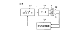
- FIG. 1 is a schematic diagram showing a configuration when the rotation angle detection device according to the first embodiment of the present invention is applied to a rotation angle detection device for detecting the rotation angle of a rotor of a brushless motor.
- FIG. 2 is a schematic diagram illustrating the configuration of the detection rotor.
- FIG. 3 is a schematic diagram showing an output signal waveform of the first magnetic sensor and an output signal waveform of the second magnetic sensor.
- FIG. 4A is a schematic diagram showing the contents of the amplitude correction table corresponding to the first magnetic sensor
- FIG. 4B is a schematic diagram showing the contents of the amplitude correction table corresponding to the second magnetic sensor.
- FIG. 5 is a flowchart showing a procedure of rotation angle calculation processing by the rotation angle calculation device.
- FIG. 5 is a flowchart showing a procedure of rotation angle calculation processing by the rotation angle calculation device.
- FIG. 6 is a flowchart illustrating an example of the control end process.
- FIG. 7 is a perspective view showing a detection rotor used in the rotation angle detection device according to the second embodiment of the present invention.
- FIG. 8 is a plan view showing a detection rotor used in the rotation angle detection device according to the second embodiment of the present invention.
- FIG. 9 is a view of the detection rotor used in the rotation angle detection device according to the third embodiment of the present invention as viewed from the end face side.
- FIG. 10 is a schematic diagram for explaining a rotation angle detection method by a conventional rotation angle detection device.
- FIG. 11 is a schematic diagram showing an output signal waveform of the first magnetic sensor and an output signal waveform of the second magnetic sensor.
- FIG. 1 is a schematic diagram showing a configuration when the rotation angle detection device according to the first embodiment of the present invention is applied to a rotation angle detection device for detecting the rotation angle of a rotor of a brushless motor.
- This rotation angle detection device has a detection rotor (hereinafter simply referred to as “rotor 1”) that rotates in accordance with the rotation of the brushless motor 10.
- the rotor 1 includes a cylindrical magnet 2 having a plurality of magnetic pole pairs corresponding to the magnetic pole pairs provided in the rotor of the brushless motor 10.
- the rotor 1 is provided with a plurality of magnetic poles arranged in the circumferential direction.
- the magnet 2 includes five magnetic pole pairs (M0, M1), (M2, M3), (M4, M5), (M6, M7), (M8, M9). That is, the magnet 2 has ten magnetic poles M0 to M9.
- the circumferential lengths of the magnetic poles provided on the rotor of the brushless motor 10 are all the same. That is, the angular widths of the magnetic poles provided on the rotor of the brushless motor 10 are all the same and are 36 °. Therefore, in this brushless motor 10, the angular width of one magnetic pole pair is 72 ° in mechanical angle, which corresponds to 360 ° in electrical angle.
- the angular widths (a, c, e, g) of the magnetic poles M0, M2, M4, M6, M8 having N poles. , I) are different from each other. That is, the magnetized areas differ between the N poles.
- the angular width (j) of the magnetic pole M9 is equal to the angular width (f) of the magnetic pole M5.
- the angular widths of the magnetic poles M0 to M9 are as shown in Table 1.
- the angle width is represented by a value obtained by multiplying the mechanical angle corresponding to the angle width by the number of magnetic pole pairs (“5” in this embodiment).
- broken lines indicate regions when the rotor 1 is divided at intervals of 36 ° (180 ° in the electrical angle) in the circumferential direction.
- two magnetic sensors 21 and 22 are arranged at an angular interval of a predetermined angle (18 ° (90 ° in the electrical angle)) around the rotation center axis of the rotor 1. .
- These two magnetic sensors 21 and 22 may be referred to as a first magnetic sensor 21 and a second magnetic sensor 22, respectively.
- a sensor provided with an element having a characteristic in which an electrical characteristic is changed by the action of a magnetic field such as a Hall element or a magnetoresistive element (MR element) can be used.
- the direction indicated by the arrow in FIG. 2 is the positive rotation direction of the rotor 1.
- the rotation angle of the rotor 1 is increased.
- the rotation angle of the rotor 1 is decreased.
- the magnetic sensors 21 and 22 output sinusoidal signals (hereinafter referred to as “sine wave signals”) V1 and V2 as the rotor 1 rotates.
- the rotor angle [deg] on the horizontal axis in FIG. 3 represents an angle obtained by multiplying the mechanical angle by the number of magnetic pole pairs (“5” in this embodiment).
- the magnetic pole regions a to j sensed by the first magnetic sensor 21 at that time are clearly specified in the vicinity of each peak value of the sine wave signal V1.
- the absolute rotation angle of the rotor 1 from a predetermined reference position is referred to as an absolute rotation angle (mechanical angle) ⁇ A of the rotor 1.
- the angle range for one rotation of the rotor 1 is divided into five sections (a + b, c + d, e + f, g + h, i + j) corresponding to the angular width of the five magnetic pole pairs, and the start position of each section is set to 0 ° and the end.
- the angle at which the position is 360 ° and the angle corresponding to the absolute rotation angle ⁇ A is represented within the range of 0 to 360 ° is referred to as the relative rotation angle ⁇ R of the rotor 1.
- the angular widths of these five sections are not constant.
- the second magnetic sensor 22 outputs five magnetic pole pairs.
- V1 and A2 each represent an amplitude.
- the amplitude A1 is different for each magnetic pole.
- the amplitude A2 is different for each magnetic pole.
- theta R represents a relative rotation angle theta R in the corresponding section.
- the relative angle ⁇ R of the rotor 1 in the corresponding section is obtained based on the following equation (3) using both the output signals V1 and V2. be able to.
- the output signals V ⁇ b> 1 and V ⁇ b> 2 of the magnetic sensors 21 and 22 are input to the rotation angle calculation device 20.
- Rotation angle calculation unit 20 based on the output signal V1, V2 of the magnetic sensors 21 and 22, to calculate the relative rotational angle theta R of the rotor 1.
- the rotation angle computing device 20 calculates the absolute rotation angle (mechanical angle) ⁇ A of the rotor 1 based on the obtained relative rotation angle ⁇ R and the like, and obtains the absolute rotation angle ⁇ A of the obtained rotor 1. based on, for calculating the electrical angle theta E of a rotor of a brushless motor.
- the rotation angle calculation device 20 is composed of, for example, a microcomputer, and includes a CPU (Central Processing Unit) and a memory (ROM, RAM, rewritable nonvolatile memory, etc.).
- the electrical angle calculated by the rotation angle calculation device 20 is given to the motor controller 30.
- the motor controller 30 controls the brushless motor 10 based on the electrical angle ⁇ E given from the rotation angle calculation device 20 and a given command value.
- ⁇ E the electrical angle
- a given command value the operation of the rotation angle calculation device 20 will be described.
- an amplitude correction table is stored for each of the magnetic sensors 21 and 22.
- FIG. 4A shows an example of the contents of an amplitude correction table (hereinafter also referred to as “first table”) corresponding to the first magnetic sensor 21.
- the first table shows the peak value (maximum value or minimum value) of the output signal V1 of the first magnetic sensor 21 corresponding to each magnetic pole number 0 to 9 of each magnetic pole M0 to M9, and the angle of the magnetic pole.
- the width [deg] and the correction gain G1 are stored.
- the angular width is a value obtained by multiplying the mechanical angle corresponding to the angular width by the number of magnetic pole pairs (“5” in this embodiment).
- the correction gain G1 is a gain for correcting variations in the amplitude of the first magnetic sensor 21 for each magnetic pole.
- the amplitude correction gain G1 for an arbitrary magnetic pole is based on the following equation (4) using the peak value (maximum value or minimum value) of the output signal V1 of the first magnetic sensor 21 corresponding to the magnetic pole and the reference amplitude. Desired.
- the reference amplitude is, for example, a value corresponding to the peak value (absolute value) of the output signal V1 of the first magnetic sensor 21 corresponding to a magnetic pole whose angular width (mechanical angle ⁇ number of magnetic pole pairs) is 180 °.
- the reference amplitude is preset and is “500” in this example.
- FIG. 4B shows an example of the contents of an amplitude correction table (hereinafter sometimes referred to as “second table”) corresponding to the second magnetic sensor 22.
- the peak value (maximum value or minimum value) of the output signal V2 of the second magnetic sensor 22 corresponding to each magnetic pole number 0 to 9 of each magnetic pole M0 to M9, the angle of the magnetic pole The width [deg] and the correction gain G2 are stored.
- the correction gain G2 is a gain for correcting variations in the amplitude of the second magnetic sensor 22 for each magnetic pole.
- the peak value of the second magnetic sensor 22 with respect to each magnetic pole is the same value as the peak value of the first magnetic sensor 21 with respect to the corresponding magnetic pole, but is actually different from each other. There is also.
- the correction gain G2 for an arbitrary magnetic pole is obtained based on the following equation (5) using the peak value (maximum value or minimum value) of the output signal V2 of the second magnetic sensor 22 corresponding to the magnetic pole and the reference amplitude. It is done.
- the reference amplitude is, for example, a value corresponding to the peak value (absolute value) of the output signal V2 of the second magnetic sensor 221 corresponding to a magnetic pole whose angular width (mechanical angle ⁇ number of magnetic pole pairs) is 180 °.
- the reference amplitude is preset and is “500” in this example.
- the peak value and the correction gain may be stored in the amplitude correction table before the brushless motor 10 is shipped, or by detecting the peak value during motor control after the brushless motor 10 is shipped. May be.
- the peak value and the correction gain stored in the amplitude correction table may be obtained from data for one period or may be obtained from an average value of data for a plurality of periods.
- the rewritable nonvolatile memory in the rotation angle calculation device 20 has a second value when the first magnetic sensor 21 detects a peak value for each magnetic pole (each magnetic pole number).
- the magnetic field specifying table (hereinafter, also referred to as “third table”) that stores data indicating the pole number of the magnetic pole sensed by the magnetic sensor 22 and the second magnetism for each magnetic pole (for each magnetic pole number).
- a magnetic pole specifying table (hereinafter referred to as “fourth table”) that stores data indicating the pole number of the magnetic pole sensed by the first magnetic sensor 21 when the sensor 22 detects the peak value for the magnetic pole. Is stored).
- the third table and the fourth table are created based on the arrangement and angular interval of both magnetic sensors 21 and 22 and the configuration of the rotor 1.
- the rotation angle calculation device 20 detects the peak value from the output signals V1 and V2 of the first or second magnetic sensor 21, 22, the amplitude correction table (first table) corresponding to one of the magnetic sensors from which the peak value has been detected.
- the pole number of the magnetic pole sensed by the magnetic sensor is specified based on the first table or the second table.
- the magnet temperature coefficient (the coefficient that decreases as the temperature increases) is used for amplitude correction.
- the table value may be corrected by multiplying the peak value of the table, and the pole number of the magnetic pole may be specified based on the detected peak value and the corrected table value.
- the rotation angle calculation device 20 cannot specify the pole number of the magnetic pole sensed by the magnetic sensor. Therefore, when the peak value corresponding to the magnetic poles other than the magnetic poles M5 and M9 is detected by one of the magnetic sensors after the start of processing, the rotation angle calculation device 20 determines the pole number of the magnetic pole sensed by the magnetic sensor. Identify.
- the rotation angle calculation device 20 specifies the pole number of the magnetic pole sensed by the other magnetic sensor based on the specified pole number and the third or fourth table (magnetic pole specifying table). For example, when the pole number of the magnetic pole sensed by the first magnetic sensor 21 is specified based on the first table, the second magnetic field is determined based on the specified pole number and the third table. The pole number of the magnetic pole sensed by the sensor 22 is specified. On the other hand, when the pole number of the magnetic pole sensed by the second magnetic sensor 22 is specified based on the second table, the first magnetic field is determined based on the specified pole number and the fourth table. The pole number of the magnetic pole sensed by the sensor 21 is specified.
- the pole number of the magnetic pole sensed by each of the magnetic sensors 21 and 22 is specified, so that the rotation angle computing device 20 senses the output signals V1 and V2 of the respective magnetic sensors 21 and 22 by detecting them. Correction is performed using correction gains G1 and G2 corresponding to the magnetic poles. Then, the rotation angle calculation unit 20 based on the output signal after amplitude correction, calculates the relative rotation angle theta R of the rotor 1. Further, the rotation angle calculation device 20 calculates the absolute rotation angle ⁇ A based on the obtained relative rotation angle ⁇ R and the like. Then, the rotation angle calculation unit 20, the absolute rotation angle theta A obtained, calculates the electrical angle theta E of the brushless motor 10.
- the rotation angle calculation device 20 calculates the relative rotation angle ⁇ R of the rotor 1, the absolute rotation angle ⁇ A , and the electrical angle ⁇ E of the brushless motor 10 in the same manner as described above.
- FIG. 5 is a flowchart showing a procedure of rotation angle calculation processing by the rotation angle calculation device 20.
- the rotation angle calculation device 20 reads the output signals (sensor values) V1 and V2 of the magnetic sensors 21 and 22 (step S1).
- the memory for example, RAM
- the rotation angle calculation device 20 stores sensor values for a plurality of times from the sensor value read a predetermined number of times to the sensor value read most recently. ing.
- the rotation angle calculation device 20 determines whether or not a peak value (extreme value) has been detected for each of the sensor values V1 and V2 based on the sensor values stored in the memory (step S2).
- the determination process in step S2 may be referred to as a peak value detection process.
- the rotation angle calculation device 20 determines that a peak value (maximum value) has been detected and identifies the maximum value. In addition, when the sensor value changes from a downward trend to an upward trend, the rotation angle calculation device 20 determines that a peak value (minimum value) has been detected and identifies the minimum value.
- step S2 when no peak value is detected (step S2: NO), the process proceeds to step S6.
- step S2: YES when the peak value is detected in step S2 (step S2: YES), the rotation angle calculation device 20 is detected by each magnetic sensor by the pole number specifying process in step S4 described later after the controller is activated. It is determined whether or not the magnetic pole has already been specified (step S3).
- step S4 When the magnetic pole sensed by each magnetic sensor is not specified (step S3: NO), the rotation angle calculation device 20 performs a pole number specifying process (step S4). That is, the rotation angle calculation device 20 specifies the magnetic poles that are detected by the magnetic sensors 21 and 22, respectively.
- the rotation angle calculation device 20 firstly corrects the peak value (maximum value or minimum value) detected by the peak value detection process in step S2 and the amplitude correction corresponding to the magnetic sensor that has output the peak value. Based on the contents of the work table (first or second table), the magnetic pole sensed by the magnetic sensor is specified. That is, the rotation angle calculation device 20 assigns the pole number corresponding to the peak value closest to the peak value detected by the peak value detection process among the plurality of peak values stored in the amplitude correction table to the magnetic sensor. Is specified as the pole number of the magnetic pole sensed by.
- the rotation angle calculation device 20 determines that the magnetic sensor is Does not identify the magnetic pole being sensed.
- the rotation angle calculation device 20 determines the pole number of the magnetic pole sensed by the magnetic sensor and the third table or the fourth table (magnetic pole). The magnetic pole sensed by the other magnetic sensor is identified based on the identification table. As a result, the magnetic pole sensed by each of the magnetic sensors 21 and 22 is specified.
- step S3 If it is determined in step S3 that the pole numbers of the magnetic poles detected by the sensors 21 and 22 have been specified by the pole number specifying process in step S4 performed after the controller is started (step S3: YES).
- the rotation angle calculation device 20 performs pole number update processing (step S5). Specifically, the rotation angle calculation device 20 uses the rotation number of the rotor 1 based on the pole number already specified for the magnetic sensor whose peak value has been detected by the peak value detection processing in step S2. Update. More specifically, the rotation angle calculation device 20 changes the pole number already specified for the magnetic sensor to a pole number that is one more or a pole number that is one less depending on the rotation direction of the rotor 1. To do.
- the already-specified pole number is updated to a pole number increased by 1, and the rotation direction of the rotor 1 is reversed. If it is, the already specified pole number is updated to a pole number that is less by one. However, the pole number that is smaller by 1 than the pole number of “0” is “9”. Further, a pole number that is 1 more than the pole number of “9” is “0”.
- the process of step S5 ends, the process proceeds to step S6.
- the rotation direction of the rotor 1 can be determined based on, for example, the phases of the output signals V1 and V2 of the magnetic sensors 21 and 22.
- step S6 the rotation angle calculation device 20 performs amplitude correction on the sensor values V1 and V2 read in step S1. Specifically, the rotation angle calculation device 20 reads the amplitude correction gains G1 and G2 corresponding to the pole numbers currently specified for the magnetic sensors 21 and 22 from the first table and the second table, respectively. Then, the rotation angle calculation device 20 corrects the sensor values V1 and V2 read in step S1 using the gains G1 and G2 read from the first table and the second table, respectively. Assuming that the corrected sensor values are V1 'and V2', V1 'and V2' are expressed by the following equations (6) and (7), respectively.
- V2 ′ V1 ⁇ G2 (7)
- step S7 the process has shifted from step S4 to step S6, and the pole number of the magnetic pole sensed by both magnetic sensors 21 and 22 is not specified in the pole number specifying process of step S4, In step S6, the sensor values V1 and V2 are not corrected, and the process proceeds to step S7.
- the rotation angle calculation device 20 specifies the magnetic pole sensed by the magnetic sensor 21 based on the pole number of the magnetic pole sensed by the magnetic sensor 21. Then, the angular width W corresponding to the specified magnetic pole is obtained. For example, when the magnetic pole sensed by the magnetic sensor 21 is the first magnetic pole M0 among the ten magnetic poles, the angular width W corresponding to the magnetic pole is 170 [deg].
- the relative angle ⁇ R of the rotor 1 calculated in step S7 is an angle calculated assuming that the magnetic pole 21 has an angular width W detected by the magnetic sensor 21 of 180 °. Therefore, the rotation angle calculation device 20 uses the relative angle ⁇ R of the rotor 1 calculated in step S7 according to the angular width of the magnetic pole region sensed by the magnetic sensor 21 based on the following equation (9). The relative angle ⁇ R ′ is converted (phase correction).
- 5 is the number of magnetic pole pairs.
- ⁇ A ⁇ R '+ (angular width of the first magnetic pole M0) ⁇ / 5.
- the angular width is a value obtained by multiplying the mechanical angle corresponding to the angular width by the number of magnetic pole pairs (“5” in this embodiment).
- ⁇ A ⁇ R '+ (the sum of the angular widths of the first and second magnetic poles M0 and M1) ⁇ / 5 It becomes.
- ⁇ A ⁇ R '+ (sum of angular widths M0 to M7 of the first to eighth magnetic poles) ⁇ / 5 Become.
- ⁇ A ⁇ R '+ (sum of angular widths M0 to M8 of the first to ninth magnetic poles) ⁇ / 5 Become.
- the rotation angle calculation device 20 calculates the electrical angle ⁇ E (step S9). Specifically, the numbers (1-5) of the magnetic pole pairs (M0, M1), (M2, M3), (M4, M5), (M6, M7), (M8, M9) sensed by the magnetic sensor 21 ) and When n, the rotation angle calculation unit 20, based on the following equation (10), to calculate the electrical angle theta E, gives the motor controller 30.
- step S10 determines whether or not the motor control is finished. If the motor control has not ended (step S10: NO), the process returns to step S1. If the motor control has been completed (step S10: YES), the rotation angle calculation device 20 performs a control end process (step S11).
- FIG. 6 is a flowchart illustrating an example of the control end process.
- the rotation angle calculation device 20 determines whether or not the brushless motor 10 has sufficiently rotated during the current motor control period (step S21). Specifically, the rotation angle calculation device 20 determines whether or not the rotation speed of the motor 10 during the current motor control period is equal to or greater than a predetermined rotation speed.
- step S21: YES the peak value corresponding to each pole number in the amplitude correction table (the first table and the second table) is represented by the pole number. Is updated to the latest detected peak value (step S22). Then, the control end process ends.
- the angular width (f) of the magnetic pole M5 of the S pole is equal to the angular width (j) of the magnetic pole M9, but the angular width of each of the magnetic poles M1, M3, M5, M7, M9 of the S pole
- the magnetic poles M0, M2, M4, M6, and M8 may be different from each other.
- 7 and 8 show a detection rotor used in the rotation angle detection device according to the second embodiment of the present invention.
- FIG. 7 is a perspective view of the detection rotor
- FIG. 8 is a view of the detection rotor as viewed from the end face side.
- the detection rotor 1A has a magnet 2A having a shape in which one end side of a cylindrical magnet is cut obliquely with respect to the axial direction. That is, one end side of the magnet 2A is a flat end surface (flat end surface), and the other end side is an inclined end surface (inclined end surface).
- the magnet 2A is magnetized with ten magnetic poles M0 to M9 at equal angular intervals in the circumferential direction when viewed from the end face side.
- the lengths of the rotor for detection 1A in the direction of the rotation axis in the magnetic poles M0 to M9 are different.
- the magnetic poles M0 to M9 have different heights.
- the two opposite sides of the inclined end surface of the rotor 1 ⁇ / b> A are opposed to the inclined end surface of the rotor 1 ⁇ / b> A in the direction opposite to the direction toward the flat end surface.
- the magnetic sensors 21 and 22 are arranged at an angular interval of a predetermined angle (18 ° (90 ° in the electrical angle)) with the rotation center axis of the rotor 1A as the center.
- the rotation angle calculation device 20 performs output signals of the magnetic sensors 21 and 22 by the same method as that of the first embodiment described above, that is, by performing substantially the same processing as that shown in FIG. Amplitude correction of V1 and V2 can be performed.
- the magnetic sensors 21 and 22 may be disposed close to the side surface (outer peripheral surface) of the rotor 1A as indicated by a broken line. However, it is necessary to dispose the magnetic sensors 21 and 22 closer to the flat end surface of the rotor 1A than the position of the inclined end surface of the magnetic pole having the shortest length in the rotation axis direction of the rotor 1A.
- the rotation angle calculation device 20 can correct the amplitude of the output signals V1 and V2 of the magnetic sensors 21 and 22 by the same method as in the first embodiment described above.
- FIG. 9 shows a detection rotor used in the rotation angle detection device according to the third embodiment of the present invention.
- the detection rotor 1B has a cylindrical magnet 2B.
- the magnet 2B is magnetized with ten magnetic poles M0 to M9 at equal angular intervals in the circumferential direction when viewed from the end face side.
- the magnitude of the magnetic force of each of the magnetic poles M0 to M9 is greatly different for each magnetic pole. That is, the magnitude of the magnetic force of each of the magnetic poles M0 to M9 is intentionally changed. Since the magnitude of the magnetic force of each of the magnetic poles M0 to M9 is greatly different for each magnetic pole, when the rotor 1B rotates, the peak value for each magnetic pole of the output signals V1 and V2 of the magnetic sensors 21 and 22 is different for each magnetic pole. Different. For this reason, the rotation angle calculation device 20 performs output signals of the magnetic sensors 21 and 22 by the same method as that of the first embodiment described above, that is, by performing substantially the same processing as that shown in FIG. Amplitude correction of V1 and V2 can be performed.
- the magnetic poles M0 ⁇ M9 are provided at equal angular intervals, in step S7 in FIG. 5, the relative angle theta R calculated based on the equation (8), the electrical angle of the brushless motor 10 It coincides with the ⁇ E. Therefore, in this embodiment, it is not necessary to perform the processing of steps S8 and S9 in FIG.
- a peak value corresponding to a magnetic pole other than the magnetic poles M5 and M9 is detected from the output signals V1 and V2 of any one of the magnetic sensors 21 and 22.
- the magnetic pole sensed by each magnetic sensor can be specified.
- the peak value of any magnetic pole is detected from the output signals V1, V2 of any one of the magnetic sensors 21, 22.
- the magnetic pole sensed by each magnetic sensor can be specified. Therefore, the magnetic pole sensed by each of the magnetic sensors 21 and 22 can be specified at an early stage immediately after the brushless motor 10 is started.
- the output signals V1 and V2 of the magnetic sensors 21 and 22 can be corrected (amplitude correction) according to the magnetic pole sensed by the magnetic sensor. it can.
- the rotation angle can be detected with high accuracy from an early stage immediately after the brushless motor 10 is started.
- the present invention can be implemented in other forms.
- the rotors 1, 1 ⁇ / b> A, 1 ⁇ / b> B have magnetic pole characteristics such that the peak value for each magnetic pole is different from any of the peak values for magnetic poles other than the magnetic pole, but at least one magnetic pole It suffices if the magnetic pole characteristics have a peak value different from that of any of the other magnetic pole values.
- the detection rotor has a magnetic pole characteristic in which the peak value for one magnetic pole (hereinafter referred to as “reference magnetic pole”) is different from any of the peak values for the other magnetic poles, the brushless motor is started.
- the magnetic pole sensed by each of the magnetic sensors 21 and 22 can be specified. Accordingly, there is a high possibility that the magnetic pole sensed by each of the magnetic sensors 21 and 22 can be specified before the detection rotor makes one rotation after the brushless motor is started. That is, the magnetic pole sensed by each of the magnetic sensors 21 and 22 can be identified at an early stage immediately after the brushless motor is started.
- the present invention can also be applied when detecting the rotation angle of a rotating body other than the rotor of a brushless motor.
Landscapes
- Physics & Mathematics (AREA)
- General Physics & Mathematics (AREA)
- Control Of Motors That Do Not Use Commutators (AREA)
- Transmission And Conversion Of Sensor Element Output (AREA)
Abstract
Priority Applications (4)
| Application Number | Priority Date | Filing Date | Title |
|---|---|---|---|
| EP11750531.3A EP2543975B1 (fr) | 2010-03-03 | 2011-02-23 | Dispositif de détection d'angle de rotation |
| CN201180012152.8A CN102782457B (zh) | 2010-03-03 | 2011-02-23 | 旋转角检测装置 |
| JP2012503084A JP5674053B2 (ja) | 2010-03-03 | 2011-02-23 | 回転角検出装置 |
| US13/579,006 US8957675B2 (en) | 2010-03-03 | 2011-02-23 | Rotation angle detection device |
Applications Claiming Priority (2)
| Application Number | Priority Date | Filing Date | Title |
|---|---|---|---|
| JP2010-046719 | 2010-03-03 | ||
| JP2010046719 | 2010-03-03 |
Publications (1)
| Publication Number | Publication Date |
|---|---|
| WO2011108421A1 true WO2011108421A1 (fr) | 2011-09-09 |
Family
ID=44542075
Family Applications (1)
| Application Number | Title | Priority Date | Filing Date |
|---|---|---|---|
| PCT/JP2011/054002 Ceased WO2011108421A1 (fr) | 2010-03-03 | 2011-02-23 | Dispositif de détection d'angle de rotation |
Country Status (5)
| Country | Link |
|---|---|
| US (1) | US8957675B2 (fr) |
| EP (1) | EP2543975B1 (fr) |
| JP (1) | JP5674053B2 (fr) |
| CN (1) | CN102782457B (fr) |
| WO (1) | WO2011108421A1 (fr) |
Cited By (5)
| Publication number | Priority date | Publication date | Assignee | Title |
|---|---|---|---|---|
| JP2014115261A (ja) * | 2012-12-12 | 2014-06-26 | Jtekt Corp | 回転角検出装置 |
| JP2015505613A (ja) * | 2012-02-01 | 2015-02-23 | ヴァレオ システム デシュヤージュValeo Systemes D’Essuyage | 電気モータのシャフトの角度位置を決定するための装置、および前記角度位置を決定するための装置を備えた風防ワイパーモータ |
| JP2015208121A (ja) * | 2014-04-21 | 2015-11-19 | 株式会社リコー | 信号増幅装置及びそれを備えた位相検出装置、並びにモータ駆動制御装置 |
| JP2017534856A (ja) * | 2014-09-24 | 2017-11-24 | ロタ エンジニアリング リミテッドRota Engineering Limited | 磁場生成器及び位置検出アセンブリ |
| WO2019150440A1 (fr) * | 2018-01-30 | 2019-08-08 | 新電元工業株式会社 | Système de commande d'entraînement, moteur, et procédé de commande de système de commande d'entraînement |
Families Citing this family (11)
| Publication number | Priority date | Publication date | Assignee | Title |
|---|---|---|---|---|
| JP2014219364A (ja) * | 2013-05-10 | 2014-11-20 | 株式会社ジェイテクト | 回転角検出装置 |
| JP6024969B2 (ja) | 2012-12-12 | 2016-11-16 | 株式会社ジェイテクト | 回転角検出装置およびそれを備えた電動パワーステアリング装置 |
| JP6086205B2 (ja) | 2012-12-12 | 2017-03-01 | 株式会社ジェイテクト | 位相差検出装置およびそれを備えた回転角検出装置 |
| JP6024970B2 (ja) | 2012-12-12 | 2016-11-16 | 株式会社ジェイテクト | 回転角検出装置およびそれを備えた電動パワーステアリング装置 |
| DE102013020578B4 (de) * | 2013-12-13 | 2017-04-27 | Tdk-Micronas Gmbh | Messsystem |
| CN104748768B (zh) * | 2015-03-12 | 2017-07-25 | 常州大学 | 转角位置检测装置的检测方法 |
| DE102016202585A1 (de) * | 2016-02-19 | 2017-08-24 | Minimax Gmbh & Co. Kg | Modularer Multisensor-Brand- und/oder Funkenmelder |
| JP6649419B2 (ja) * | 2018-03-26 | 2020-02-19 | ファナック株式会社 | エンコーダの信号処理装置、及びエンコーダ |
| JP7056367B2 (ja) * | 2018-05-17 | 2022-04-19 | トヨタ自動車株式会社 | 認識エラー検出装置、電動ブレーキ制御装置 |
| US10914609B2 (en) | 2018-06-19 | 2021-02-09 | Nxp B.V. | System and method for angle sensing using magnet having asymmetric magnetization configuration |
| US12424910B2 (en) | 2022-12-31 | 2025-09-23 | Cooper-Standard Automotive Inc. | Apparatus and method for magnetically sensing the position of a rotating device |
Citations (4)
| Publication number | Priority date | Publication date | Assignee | Title |
|---|---|---|---|---|
| JPH06323867A (ja) * | 1993-05-14 | 1994-11-25 | Kayaba Ind Co Ltd | 位置検出装置 |
| JP2002257649A (ja) | 2001-02-27 | 2002-09-11 | Koyo Seiko Co Ltd | 回転角検出装置、トルク検出装置及び舵取装置 |
| JP2003083823A (ja) * | 2001-09-14 | 2003-03-19 | Koyo Seiko Co Ltd | 回転角検出装置、トルク検出装置及び舵取装置 |
| JP2009503462A (ja) * | 2005-07-26 | 2009-01-29 | エーベーエム−パプスト ザンクト ゲオルゲン ゲーエムベーハー ウント コー.カーゲー | 絶対値回転角センサを有する電気モータ、および回転角絶対値の形成方法 |
Family Cites Families (15)
| Publication number | Priority date | Publication date | Assignee | Title |
|---|---|---|---|---|
| US5461311A (en) * | 1992-12-24 | 1995-10-24 | Kayaba Kogyo Kabushiki Kaisha | Rod axial position detector including plural scales wherein nonmagnetized portions have differing spacing and differing depths and means for calculating the absolute position are provided |
| US6029363A (en) * | 1998-04-03 | 2000-02-29 | Mitutoyo Corporation | Self-calibrating position transducer system and method |
| US20020124663A1 (en) | 1999-04-07 | 2002-09-12 | Yoshitomo Tokumoto | Rotational angle detecting device, torque detecting device and steering apparatus |
| WO2001020351A1 (fr) * | 1999-09-17 | 2001-03-22 | Delphi Technologies, Inc. | Procede economique servant a mesurer la position rotative haute resolution de machines electriques |
| JP2001114116A (ja) * | 1999-10-19 | 2001-04-24 | Alps Electric Co Ltd | 回転角検出装置 |
| US6172499B1 (en) * | 1999-10-29 | 2001-01-09 | Ascension Technology Corporation | Eddy current error-reduced AC magnetic position measurement system |
| US6305234B1 (en) * | 2000-01-27 | 2001-10-23 | Edward L. Thies | Absolute encoder |
| JP2005208028A (ja) * | 2003-12-22 | 2005-08-04 | Minebea Co Ltd | バリアブルリラクタンスレゾルバ用角度演算方法とそのための角度演算装置 |
| JP2006145220A (ja) | 2004-11-16 | 2006-06-08 | Shicoh Eng Co Ltd | 磁気式位置検出装置 |
| WO2007145296A1 (fr) * | 2006-06-14 | 2007-12-21 | The Furukawa Electric Co., Ltd. | Détecteur d'angle de rotation |
| JP4858837B2 (ja) * | 2006-10-26 | 2012-01-18 | 株式会社デンソー | 回転角度検出装置 |
| FR2909170B1 (fr) * | 2006-11-28 | 2010-01-29 | Moving Magnet Tech Mmt | Capteur de position linaire ou rotatif a profil d'aimant variable preferentiellement de maniere quasi sinusoidal. |
| JP4330083B2 (ja) * | 2007-05-18 | 2009-09-09 | 株式会社日本自動車部品総合研究所 | 回転角度検出装置 |
| JP5077717B2 (ja) | 2010-04-12 | 2012-11-21 | 村田機械株式会社 | 磁極検出システム |
| US9518844B2 (en) * | 2010-04-16 | 2016-12-13 | Jtekt Corporation | Rotation angle detection device compromising |
-
2011
- 2011-02-23 WO PCT/JP2011/054002 patent/WO2011108421A1/fr not_active Ceased
- 2011-02-23 CN CN201180012152.8A patent/CN102782457B/zh not_active Expired - Fee Related
- 2011-02-23 JP JP2012503084A patent/JP5674053B2/ja not_active Expired - Fee Related
- 2011-02-23 US US13/579,006 patent/US8957675B2/en not_active Expired - Fee Related
- 2011-02-23 EP EP11750531.3A patent/EP2543975B1/fr not_active Not-in-force
Patent Citations (4)
| Publication number | Priority date | Publication date | Assignee | Title |
|---|---|---|---|---|
| JPH06323867A (ja) * | 1993-05-14 | 1994-11-25 | Kayaba Ind Co Ltd | 位置検出装置 |
| JP2002257649A (ja) | 2001-02-27 | 2002-09-11 | Koyo Seiko Co Ltd | 回転角検出装置、トルク検出装置及び舵取装置 |
| JP2003083823A (ja) * | 2001-09-14 | 2003-03-19 | Koyo Seiko Co Ltd | 回転角検出装置、トルク検出装置及び舵取装置 |
| JP2009503462A (ja) * | 2005-07-26 | 2009-01-29 | エーベーエム−パプスト ザンクト ゲオルゲン ゲーエムベーハー ウント コー.カーゲー | 絶対値回転角センサを有する電気モータ、および回転角絶対値の形成方法 |
Non-Patent Citations (1)
| Title |
|---|
| See also references of EP2543975A4 * |
Cited By (7)
| Publication number | Priority date | Publication date | Assignee | Title |
|---|---|---|---|---|
| JP2015505613A (ja) * | 2012-02-01 | 2015-02-23 | ヴァレオ システム デシュヤージュValeo Systemes D’Essuyage | 電気モータのシャフトの角度位置を決定するための装置、および前記角度位置を決定するための装置を備えた風防ワイパーモータ |
| US9912216B2 (en) | 2012-02-01 | 2018-03-06 | Valeo Systèmes d'Essuyage | Arrangement for determining the angular position of a shaft of an electric motor, and windscreen wiper motor with an arrangement for determining the angular position |
| JP2014115261A (ja) * | 2012-12-12 | 2014-06-26 | Jtekt Corp | 回転角検出装置 |
| JP2015208121A (ja) * | 2014-04-21 | 2015-11-19 | 株式会社リコー | 信号増幅装置及びそれを備えた位相検出装置、並びにモータ駆動制御装置 |
| JP2017534856A (ja) * | 2014-09-24 | 2017-11-24 | ロタ エンジニアリング リミテッドRota Engineering Limited | 磁場生成器及び位置検出アセンブリ |
| WO2019150440A1 (fr) * | 2018-01-30 | 2019-08-08 | 新電元工業株式会社 | Système de commande d'entraînement, moteur, et procédé de commande de système de commande d'entraînement |
| JP6577145B1 (ja) * | 2018-01-30 | 2019-09-18 | 新電元工業株式会社 | 駆動制御システム、モータ、および、駆動制御システムの制御方法 |
Also Published As
| Publication number | Publication date |
|---|---|
| CN102782457B (zh) | 2015-11-25 |
| EP2543975A4 (fr) | 2015-08-26 |
| JPWO2011108421A1 (ja) | 2013-06-27 |
| US8957675B2 (en) | 2015-02-17 |
| US20120319680A1 (en) | 2012-12-20 |
| EP2543975A1 (fr) | 2013-01-09 |
| JP5674053B2 (ja) | 2015-02-25 |
| CN102782457A (zh) | 2012-11-14 |
| EP2543975B1 (fr) | 2017-05-17 |
Similar Documents
| Publication | Publication Date | Title |
|---|---|---|
| JP5674053B2 (ja) | 回転角検出装置 | |
| JP5725377B2 (ja) | 回転角検出装置 | |
| JP5776925B2 (ja) | 回転角検出装置 | |
| JP5333863B2 (ja) | 回転角検出装置 | |
| US8836326B2 (en) | Rotation angle detection device | |
| US7233139B2 (en) | Method and apparatus for sensing angle of rotation which compensates an output signal from a magnetic sensor element irrespective of the range of rotational angles of a target object | |
| JP5660381B2 (ja) | 回転角検出装置 | |
| EP2477003B1 (fr) | Dispositif de détection d'angle de rotation | |
| US8781777B2 (en) | Rotation angle detection device and electric power steering system using the same | |
| JP6210284B2 (ja) | 回転角検出装置 | |
| WO2019167763A1 (fr) | Procédé d'estimation de position, dispositif d'estimation de position, et module de moteur | |
| KR20170106209A (ko) | 로터리 인코더 및 로터리 인코더의 각도 보정 방법 | |
| JP2012189376A (ja) | 回転角検出装置およびトルク検出装置 | |
| JP5892359B2 (ja) | 回転角検出装置 | |
| US9625249B2 (en) | Rotation angle detection device and electric power steering system including the same | |
| JP2011047735A (ja) | 回転角検出装置 | |
| JP5708986B2 (ja) | 回転角検出装置 | |
| JP2022184555A (ja) | 回転角度検出装置及び回転角度の導出方法 | |
| JP2012237619A (ja) | 回転角検出装置 | |
| WO2024143256A1 (fr) | Dispositif de détection d'angle | |
| JP2004077133A (ja) | 回転角度検出装置の初期設定方法 |
Legal Events
| Date | Code | Title | Description |
|---|---|---|---|
| WWE | Wipo information: entry into national phase |
Ref document number: 201180012152.8 Country of ref document: CN |
|
| 121 | Ep: the epo has been informed by wipo that ep was designated in this application |
Ref document number: 11750531 Country of ref document: EP Kind code of ref document: A1 |
|
| WWE | Wipo information: entry into national phase |
Ref document number: 2012503084 Country of ref document: JP |
|
| WWE | Wipo information: entry into national phase |
Ref document number: 13579006 Country of ref document: US |
|
| REEP | Request for entry into the european phase |
Ref document number: 2011750531 Country of ref document: EP |
|
| WWE | Wipo information: entry into national phase |
Ref document number: 2011750531 Country of ref document: EP |
|
| NENP | Non-entry into the national phase |
Ref country code: DE |