WO2011108423A1 - ソレノイドバルブ - Google Patents
ソレノイドバルブ Download PDFInfo
- Publication number
- WO2011108423A1 WO2011108423A1 PCT/JP2011/054012 JP2011054012W WO2011108423A1 WO 2011108423 A1 WO2011108423 A1 WO 2011108423A1 JP 2011054012 W JP2011054012 W JP 2011054012W WO 2011108423 A1 WO2011108423 A1 WO 2011108423A1
- Authority
- WO
- WIPO (PCT)
- Prior art keywords
- valve
- chamber
- pressure
- solenoid
- poppet
- Prior art date
- Legal status (The legal status is an assumption and is not a legal conclusion. Google has not performed a legal analysis and makes no representation as to the accuracy of the status listed.)
- Ceased
Links
Images


Classifications
-
- F—MECHANICAL ENGINEERING; LIGHTING; HEATING; WEAPONS; BLASTING
- F16—ENGINEERING ELEMENTS AND UNITS; GENERAL MEASURES FOR PRODUCING AND MAINTAINING EFFECTIVE FUNCTIONING OF MACHINES OR INSTALLATIONS; THERMAL INSULATION IN GENERAL
- F16K—VALVES; TAPS; COCKS; ACTUATING-FLOATS; DEVICES FOR VENTING OR AERATING
- F16K31/00—Actuating devices; Operating means; Releasing devices
- F16K31/02—Actuating devices; Operating means; Releasing devices electric; magnetic
- F16K31/06—Actuating devices; Operating means; Releasing devices electric; magnetic using a magnet, e.g. diaphragm valves, cutting off by means of a liquid
- F16K31/0603—Multiple-way valves
- F16K31/0624—Lift valves
-
- Y—GENERAL TAGGING OF NEW TECHNOLOGICAL DEVELOPMENTS; GENERAL TAGGING OF CROSS-SECTIONAL TECHNOLOGIES SPANNING OVER SEVERAL SECTIONS OF THE IPC; TECHNICAL SUBJECTS COVERED BY FORMER USPC CROSS-REFERENCE ART COLLECTIONS [XRACs] AND DIGESTS
- Y10—TECHNICAL SUBJECTS COVERED BY FORMER USPC
- Y10T—TECHNICAL SUBJECTS COVERED BY FORMER US CLASSIFICATION
- Y10T137/00—Fluid handling
- Y10T137/8593—Systems
- Y10T137/86493—Multi-way valve unit
- Y10T137/86574—Supply and exhaust
- Y10T137/8667—Reciprocating valve
- Y10T137/86694—Piston valve
- Y10T137/86702—With internal flow passage
-
- Y—GENERAL TAGGING OF NEW TECHNOLOGICAL DEVELOPMENTS; GENERAL TAGGING OF CROSS-SECTIONAL TECHNOLOGIES SPANNING OVER SEVERAL SECTIONS OF THE IPC; TECHNICAL SUBJECTS COVERED BY FORMER USPC CROSS-REFERENCE ART COLLECTIONS [XRACs] AND DIGESTS
- Y10—TECHNICAL SUBJECTS COVERED BY FORMER USPC
- Y10T—TECHNICAL SUBJECTS COVERED BY FORMER US CLASSIFICATION
- Y10T137/00—Fluid handling
- Y10T137/8593—Systems
- Y10T137/86493—Multi-way valve unit
- Y10T137/86574—Supply and exhaust
- Y10T137/8667—Reciprocating valve
- Y10T137/86694—Piston valve
- Y10T137/8671—With annular passage [e.g., spool]
-
- Y—GENERAL TAGGING OF NEW TECHNOLOGICAL DEVELOPMENTS; GENERAL TAGGING OF CROSS-SECTIONAL TECHNOLOGIES SPANNING OVER SEVERAL SECTIONS OF THE IPC; TECHNICAL SUBJECTS COVERED BY FORMER USPC CROSS-REFERENCE ART COLLECTIONS [XRACs] AND DIGESTS
- Y10—TECHNICAL SUBJECTS COVERED BY FORMER USPC
- Y10T—TECHNICAL SUBJECTS COVERED BY FORMER US CLASSIFICATION
- Y10T137/00—Fluid handling
- Y10T137/8593—Systems
- Y10T137/86919—Sequentially closing and opening alternately seating flow controllers
-
- Y—GENERAL TAGGING OF NEW TECHNOLOGICAL DEVELOPMENTS; GENERAL TAGGING OF CROSS-SECTIONAL TECHNOLOGIES SPANNING OVER SEVERAL SECTIONS OF THE IPC; TECHNICAL SUBJECTS COVERED BY FORMER USPC CROSS-REFERENCE ART COLLECTIONS [XRACs] AND DIGESTS
- Y10—TECHNICAL SUBJECTS COVERED BY FORMER USPC
- Y10T—TECHNICAL SUBJECTS COVERED BY FORMER US CLASSIFICATION
- Y10T137/00—Fluid handling
- Y10T137/8593—Systems
- Y10T137/87169—Supply and exhaust
- Y10T137/87217—Motor
Definitions
- the present invention relates to a solenoid valve used for, for example, hydraulic control of an automatic transmission.
- a spool is slidably disposed along the inner peripheral surface of a sleeve having a port formed on the side surface, and the position of the spool is controlled by electromagnetic force from a solenoid and mechanical force such as a spring, thereby
- a spool valve type solenoid valve for controlling pressure is widely used.
- this type of solenoid valve it is necessary to provide a clearance between the sleeve and the spool, and it is difficult to completely prevent leakage from both.
- As a method of reducing this leakage it is possible to increase the length of the sliding portion or to minimize the clearance.
- both require high-precision processing and increase the processing cost. .
- Patent Document 1 Japanese Patent No. 3994871
- Patent Document 2 PCT International Publication No. WO2009 / 025366
- 3999471 is a first poppet valve installed in a partition plate disposed in a communication chamber formed between an input port and an output port; A second poppet valve installed on the side opposite to the side communicating with the input port of the communication chamber communicating with the output port, and a seal sliding diameter of the inner peripheral hole of the partition plate (of the first poppet valve)
- the fluid pressure can be controlled in proportion to the output of the solenoid.
- control valve described in PCT International Publication No. WO2009 / 025366 integrally forms the valve portion of the first poppet valve and the valve portion of the second poppet valve, and this valve portion body is formed by a bellows.
- the first pressure-sensitive spring device is configured to support the valve seat body of the second poppet valve by a second pressure-sensitive spring device configured from a bellows, and the pressure-receiving area of the first pressure-sensitive spring device.
- the pressure receiving area of the second pressure-sensitive spring device, the seating diameter of the valve portion of the first poppet valve, and the seating diameter of the valve portion of the second poppet valve are made substantially equal to each other. It is what you do.
- the seal sliding diameter (second seal sliding diameter) of the valve seat body of the second poppet valve is set larger than the seating diameter (contact diameter) of the second poppet valve.
- the present invention has been made in view of such problems, and an object of the present invention is to provide a solenoid valve that can reliably and accurately control the flow rate, can reduce costs, and is small and has a high pressure resistance. It is in.
- the present invention is a solenoid valve for controlling the flow rate of fluid
- the inside is formed in a valve space chamber that penetrates in the axial direction, and the valve space chamber is formed in order in the axial direction by the first partition portion, the second partition portion, and the third partition portion in which the inner peripheral diameter is smaller than the surroundings.
- a main body partitioned into a first pressure chamber, a first valve chamber, a second valve chamber and a second pressure chamber;
- a supply port through which fluid of a desired supply pressure flows into and out of the main body through the first valve chamber of the main body;
- An output port through which fluid of a desired control pressure flows into and out of the main body through the second valve chamber of the main body;
- a discharge port through which a fluid having a desired discharge pressure flows in and out of one or both of the first pressure sensing chamber and the second pressure sensing chamber of the main body and the outside of the main body;
- a member disposed in the first pressure-sensitive chamber, the first valve chamber, and the second valve chamber of the main body so as to be movable in the axial direction.
- a first valve member having therein a first communication passage communicating the pressure chamber side and the second valve chamber side;
- a second valve member having a second communication passage communicating with the side, Either the valve body or the valve seat body formed in the second partition part that partitions the first valve chamber and the second valve chamber, and the valve body or valve seat body formed in the first valve member
- a first poppet valve that opens and closes between the first valve chamber through which fluid flows through the supply port and the second valve chamber through which fluid flows through the output port ,
- One of the valve body and the valve seat formed at the end of the first valve member on the second valve chamber side and formed in the second valve chamber, and the second valve chamber of the second valve member A valve body or a valve seat formed in the second valve chamber, and in the valve open state, the first communication path, the second communication path, and the second A second poppet valve that communicates with the two valve chambers and communicates the first communication path and the second communication path in a closed state;
- a first pressure sensing portion formed integrally with the first valve member and slidably disposed on an inner periphery of the first partitioning portion partitioning the first pressure sensing chamber and
- a second spring that applies an elastic force in a direction opposite to the magnetic force applied by the solenoid portion to the second valve member;
- a first pressure receiving area that is a seating area of the first poppet valve;
- a second pressure receiving area that is a seating area of the second poppet valve;
- a third pressure receiving area that is a pressure receiving area of the first pressure sensing portion;
- the fourth pressure receiving area which is the pressure receiving area of the second pressure sensing portion, is substantially equal.
- the inner periphery of the partition portion and the first slide sliding with the inner periphery.
- a seal member such as an O-ring is disposed on one or both of the pressure-sensitive part and the outer periphery of the second pressure-sensitive part.
- FIG. 1 is a diagram showing the configuration of the solenoid valve according to the first embodiment of the present invention.
- FIG. 2 is a diagram showing the configuration of the solenoid valve according to the second embodiment of the present invention.
- FIG. 3 is a diagram showing the configuration of the solenoid valve according to the third embodiment of the present invention.
- FIG. 4 is a diagram showing the configuration of the solenoid valve according to the fourth embodiment of the present invention.
- FIG. 5 is a diagram showing the configuration of the solenoid valve according to the fifth embodiment of the present invention.
- FIG. 6 is a diagram showing the configuration of the solenoid valve according to the sixth embodiment of the present invention.
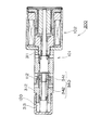
- FIG. 1 is a sectional view of a solenoid valve 100 according to the present invention. As shown in FIG. 1, the solenoid valve 100 is formed by integrally connecting a control valve portion 101 and a solenoid portion 102.
- the control valve unit 101 includes a main body 110 as an outer frame and a valve space chamber 120 penetrating in the axial direction inside the main body 110.
- the valve space chamber 120 is divided into first pressure sensitive chamber 121, first valve chamber 122, second valve chamber 123, and second pressure sensitive chamber 124 by being divided by first to third partition portions 111 to 113. Is done.
- the main body 110 is made of a metal such as iron, brass, copper, aluminum, and stainless steel, an industrial plastic, a synthetic resin material such as a special resin.
- the main body 110 includes a discharge port 131 penetrating from the first pressure sensing chamber 121 outward in the axial direction, a supply port 132 penetrating from the outer peripheral surface to the first valve chamber 122, and from the outer peripheral surface to the second valve chamber 123.
- a penetrating output port 133 is formed.
- a plurality of supply ports 132 and output ports 133 are provided along the outer peripheral surface.
- a fluid having a supply pressure Po flows into the supply port 132, a fluid having a control pressure Pc flows out or flows into the output port 133, and a fluid having a discharge pressure Pd is discharged from the discharge port 131.
- the outer surface of the end portion of the main body 110 on the solenoid portion 102 side is formed on a mounting surface 114 to which the solenoid portion 102 is attached, and that end portion, that is, the end portion of the second pressure sensing chamber 124 on the solenoid portion 102 side is formed.
- a through hole 134 for the solenoid rod 186 that penetrates the end portion in the axial direction is provided.
- a peripheral surface of a hole communicating the first pressure sensing chamber 121 and the first valve chamber 122 of the first partition 111 of the main body 110 is formed on the first sliding surface 111A.
- An outer peripheral surface of a first pressure-sensitive portion 145 having a cylindrical shape of a valve body 140 described later is passed through the first sliding surface 111A with a slight clearance and is slid in the axial direction.
- a valve hole surface 112A is formed on the peripheral surface of the hole communicating the first valve chamber 122 and the second valve chamber 123 of the second partition 112, and the end of the valve hole surface 112A on the first valve chamber 122 side.
- the first valve seat surface 112B constituting the first poppet valve 103 is formed.
- the peripheral surface of the hole communicating the second valve chamber 123 and the second pressure sensing chamber 124 of the third partition 113 is formed on the second sliding surface 113A.
- the valve body 140 (corresponding to the first valve member in the claims) is formed with a cylindrical first pressure-sensitive portion 145 and a first valve body 142 at one end of a cylindrical body portion 141.
- the second valve body 143 is formed on the other end.
- the valve body 140 is a member in which the first valve body 142, the second valve body 143, and the first pressure sensing unit 145 are integrated.
- the valve body 140 is arranged so that the second partition body 112 is interposed between the first valve body 142 and the second valve body 143 with the end on the second valve body 143 side facing the solenoid section 102.
- the control valve unit 101 is disposed in the valve space chamber 120 of the main body 110.
- the valve body 140 is assembled, for example, by fitting the outer peripheral surface of the end portion of the body portion 141 to a fitting hole provided at the end portion of the first valve portion 142 and connecting them to the above arrangement. Is done.
- the material of the valve body 140 is, for example, a metal such as brass, copper, aluminum, or stainless steel, or a synthetic resin material.
- a first valve body 142 is disposed in the first valve chamber 122.
- the first valve body 142 is formed with a first valve portion surface 142A that is a tapered surface that has a smaller diameter toward the body portion 141, in other words, a smaller diameter toward the second partition portion 112 of the main body 110. ing.
- the first valve portion surface 142A joins with the first valve seat surface 112B and closes the valve. Further, when the valve body 140 moves away from the solenoid portion 102 and the tapered surface is separated from the first valve seat surface 112B, the valve is opened.
- the first valve portion surface 142A and the first valve seat surface 112B are configured as the first poppet valve 103 having a shape in which the cylindrical surface does not fit. Since the poppet valve is such that the valve portion surface contacts (sits) with a slight width on the valve seat surface, sliding resistance can be avoided when the valve is opened and closed. Note that the cross-sectional area (sitting area) of the inner diameter portion where the first valve portion surface 142A and the first valve seat surface 112B are joined (seats) is the first pressure receiving area S1 that receives the pressure of the working fluid.
- the body portion 141 of the valve body 140 is disposed loosely inside the valve hole surface 112 ⁇ / b> A of the second partition portion 112 of the main body 110.
- the first flow passage 125 is formed between the body portion 141 of the valve body 140 and the valve hole surface 112A. Become. Accordingly, when the first poppet valve 103 is opened, the fluid having the supply pressure Po flows from the first valve chamber 122 through the first flow passage 125 and is supplied to the second valve chamber 123.
- the body part 141 of the valve body 140 is arranged loosely inside the valve hole surface 112A of the second partitioning part 112 of the main body 110, so that even when the valve body 140 moves, the body part 141 and A space is formed between the valve hole surface 112A and no contact is made. Therefore, the movement of the valve body 140 is not accompanied by sliding resistance. Further, even if deposits adhere to the body part 141, the body part 141 and the valve hole surface 112A do not slide, so that the solenoid valve 100 does not malfunction.
- a second valve body 143 is disposed in the second valve chamber 123.
- the second valve body 143 is formed at the end of the valve body 140 on the solenoid part 102 side.
- the second valve body 143 is formed with a second valve portion surface 143A that is a tapered surface that has a smaller diameter toward the tip, in other words, a tapered surface that has a smaller diameter toward the valve seat body 150 described later.
- the second valve portion surface 143A is a valve seat portion in which the valve seat body 150 moves toward the valve body 140 and the tapered surface of the second valve body 143 is formed at the end of the valve seat body 150 on the valve body 140 side.
- the second valve seat surface 152B is joined and closed. Further, when the valve seat body 150 moves away from the valve body 140 and the taper surface is separated from the second valve seat surface 152B, the valve is opened.
- the second valve portion surface 143A and the second valve seat surface 152B are configured as the second poppet valve 104 having a shape in which the cylindrical surface is not fitted.
- the second poppet valve 104 is such that the valve portion surface contacts (sits) with a slight width so as not to cause sliding resistance when the valve is opened and closed. it can.
- the cross-sectional area (sitting area) of the inner diameter portion where the second valve portion surface 143A and the second valve seat surface 152B join (seat) is the second pressure receiving area S2 that receives the pressure of the working fluid.
- a first communication passage 146 that penetrates from the first pressure sensing portion 145 to the second valve body 143 is formed inside the valve body 140.
- a first pressure sensing part 145 is arranged at the end opposite to the solenoid part 102.
- the first pressure sensing part 145 is a bottomed cylindrical part whose end side opens into the first pressure sensing chamber 121, and its outer peripheral surface is on the first sliding surface 111 ⁇ / b> A of the first partition part 111 of the main body 110. It is slidably fitted in the axial direction.
- An end opening of the first communication passage 146 that penetrates to the second valve body 143 is formed on the surface on the first valve body 142 side that is the bottom surface of the cylindrical first pressure-sensitive portion 145.
- a first spring 161 is installed on the inner peripheral part of the cylindrical first pressure-sensitive part 145. One end portion of the first spring 161 is connected to the bottom surface of the cylindrical first pressure sensing portion 145, and the other end portion of the first spring 161 is the discharge port of the first pressure sensing chamber 121. 131 is connected to the end surface on which 131 is formed. The first spring 161 presses the valve element 140 in the direction of the solenoid unit 102 by spring force F1.
- the first pressure sensing chamber 121 has a first communication passage 146 when the second valve portion surface 143A of the second valve body 143 of the valve body 140 is opened away from the second valve seat surface 152B of the valve seat body 150.
- the second valve chamber 123 communicates with the second valve chamber 123. Further, the first pressure sensing chamber 121 is closed when the second valve portion surface 143A of the second valve body 143 is in close contact with the second valve seat surface 152B of the valve seat body 150 and is closed.
- the second pressure sensing chamber 124 communicates with the second communication passage 156.
- the area where the first pressure sensing unit 145 receives the supply pressure Po is a third pressure receiving area S3.
- a valve seat 150 is disposed on the solenoid unit 102 side of the valve body 140 inside the main body 110 so as to be movable in the axial direction.
- the valve seat body 150 (corresponding to the second valve member in the claims) has a cylindrical valve seat portion 152 formed at the end of the cylindrical body portion 151 on the valve body 140 side, and the body portion 151.
- a second pressure-sensitive portion 155 is formed on the solenoid portion 102 side.
- the end of the solenoid rod 186 is connected to the end of the valve seat 150 on the side of the solenoid 102.
- the end of the valve seat 150 on the solenoid part 102 side is formed with a flange part 153 in the outer diameter direction, and between the flange part 153 and the annular side surface of the third partition part 113 on the solenoid part 102 side.
- a second spring 162 is installed.
- the second spring 162 is an extension spring that biases the solenoid rod 186 to the right side in the drawing, that is, the solenoid unit 102 side.
- the pressure receiving area of the second pressure sensing unit 155 is the fourth pressure receiving area S4.
- the second valve seat surface 152B provided at the inner peripheral corner of the valve seat 140 side end of the valve seat portion 150 of the valve seat body 150 is similar to the second valve portion surface 143A of the second valve body 143 of the valve body 140. Separates and forms an on-off valve. As described above, the second valve seat surface 152B and the second valve portion surface 143A constitute the second poppet valve 104 that has a small joining width and opens and closes. Further, the area for receiving the fluid of the control pressure Pc in the cross section of the inner diameter portion where the second valve seat surface 152B and the second valve portion surface 143A are joined is the second pressure receiving area S2.
- the first pressure receiving area (the seating area of the first poppet valve 103) S1
- the second pressure receiving area (the seating area of the second poppet valve 104)
- the third pressure receiving area (the first pressure sensing portion) described above.
- 145 pressure-receiving area) S3 and fourth pressure-receiving area (pressure-receiving area of the second pressure-sensitive portion 155) S4 are both substantially equal. It should be noted that substantially the same effect can be achieved within the range of ⁇ 6%.
- valve seat body 150 is formed with a second communication passage 156 that allows the bottom of the cylindrical valve seat portion 152 to communicate with the second pressure sensing chamber 124.
- the second communication passage 156 allows the fluid in the second valve chamber 123 to be introduced into the second pressure sensing chamber 124 in which the second spring 162 is disposed when the second poppet valve 104 is opened.
- the second communication path 156 always communicates the second pressure sensing chamber 124 with the first communication path 146, the first pressure sensing chamber 121, and the discharge port 131.
- the fluid flowing into the second pressure sensing chamber 124 acts on each member in the communicating solenoid unit 102 to balance the pressure so that the fluid pressure does not act on only one surface (from the second pressure sensing chamber 124).
- the fluid also flows into the solenoid portion 102).
- valve seat body 150 When the solenoid portion 102 is not operated by the valve seat body 150 configured as described above, the valve seat body 150 is separated from the valve body 140 by the spring force F2 of the second spring 162, and the second poppet valve 104 is opened. To do. When the second poppet valve 104 is opened, the second valve chamber 123 and the second pressure sensing chamber 124 communicate with each other via the second communication passage 156, and the control pressure is supplied from the second valve chamber 123 to the second pressure sensing chamber 124. Pc fluid can flow.
- the solenoid part 102 is connected to the mounting surface 114 of the control valve part 101 as described above.
- the solenoid unit 102 is provided with a movable core 181 inside, and a solenoid rod 186 is coupled to the movable core 181.
- a fixed core 182 is provided at a position opposite to the movable core 181, and an electromagnetic coil 183 is disposed around the movable core 181 and the fixed core 182 to constitute an electromagnetic circuit.
- the movable core 181 is attracted to the fixed core 182 by the magnetic force F generated in the electromagnetic circuit according to the magnitude of the current.
- the solenoid rod 186 integrated with the movable core 181 moves together with the movable core 181 and presses the valve seat 150 while compressing the second spring 162.
- the valve seat body 150 moves, the valve seat body 150 moves the valve body 140 to the left in the figure while closing the valve body 140, and the first valve portion surface 142A is disengaged from the first valve seat surface 112B.
- the 1 poppet valve 103 is opened. At this time, the first spring 161 is also compressed.
- the operation of the solenoid valve 100 having such a configuration will be described.
- the magnetic force F does not act between the movable core 181 and the fixed core 182 of the solenoid unit 102, and the movable core 181 and the fixed core 182 are separated from each other.
- the valve seat body 150 is pushed to the solenoid part 102 side by the extension force of the spring force F2 of the second spring 162.
- the second valve seat surface 152B of the valve seat portion 152 is separated from the second valve portion surface 143A of the valve body 140, and the second poppet valve 104 is in the open state with the maximum stroke (opening amount).
- the fluid can flow from the second valve chamber 123 to the first communication path 146, and the fluid at the control pressure Pc flows from the second valve chamber 123 to the first communication path.
- 146 and the first pressure sensing chamber 121 are discharged to the discharge port 131, and the control pressure Pc decreases. That is, when the current to the solenoid unit 102 is stopped, the control pressure Pc is reduced.
- the second pressure sensing chamber 124 communicates with the second valve chamber 123 via the second communication passage 156, and the second pressure sensing chamber 124, the second valve chamber 123 and the first pressure sensing chamber 121 are both in the same pressure state.
- the valve element 140 is pressed by the spring force F1 of the first spring 161 disposed in the first pressure sensing chamber 121, and the first valve portion surface 142A is The first valve seat surface 112B is joined. That is, the first poppet valve 103 composed of the first valve portion surface 142A and the first valve seat surface 112B is in a closed state in which the stroke (opening amount) is zero. For this reason, the fluid of the supply pressure Po supplied from the supply port 132 is interrupted
- the first pressure receiving area S1, the second pressure receiving area S2, the third pressure receiving area S3, and the fourth pressure receiving area S4 are all configured to be the same area. Therefore, the mutual force received from the working fluid is cancelled.
- a magnetic force F acts between the movable core 181 and the fixed core 182 of the solenoid unit 102, and the movable core 181 and the fixed core 182 are brought into a close state.
- the valve seat 150 moves to a position away from the solenoid portion 102 side against the extension force of the spring force F2 of the second spring 162.
- the second valve seat surface 152B of the valve seat portion 152 is close to the second valve portion surface 143A, and the stroke (opening amount) of the second poppet valve 104 is reduced.
- the magnetic force F, the proximity state of the movable core 181 and the fixed core 182, the movement position of the valve seat 150 and the stroke (opening amount) of the second poppet valve 104 are determined by the amount of current applied to the solenoid unit 102. That is, as the amount of current applied to the solenoid unit 102 increases, the magnetic force F acting between the movable core 181 and the fixed core 182 of the solenoid unit 102 increases, so that the movable core 181 and the fixed core 182 are closer to each other.
- the valve seat body 150 moves to a position further away from the solenoid portion 102 side, and the stroke (opening amount) of the second poppet valve 104 becomes smaller. As a result, the second valve chamber 123 and the first communication path The flow of the fluid with 146 will be in the state where it is suppressed more.
- valve seat body 150 moves to a position where the second valve seat surface 152B is joined to the second valve portion surface 143A of the valve body 140, and the second poppet The stroke (opening amount) of the valve 104 is zero, and the second poppet valve 104 is closed. In this state, the flow of fluid from the second valve chamber 123 to the first communication passage 146 is interrupted, and the outflow of the control pressure Pc flowing through the output port 133 toward the discharge port 131 is stopped.
- the first poppet valve 103 In this state, that is, in a state where the valve seat body 150 is simply moved to a position where the second valve seat surface 152B is joined to the second valve portion surface 143A, the first poppet valve 103 still has zero stroke (amount of opening). The first poppet valve 103 and the second poppet valve 104 are both closed.
- the second valve portion surface 143A is joined to the second valve seat surface 152B of the valve seat portion 152, thereby integrating the valve seat body 150 with the valve.
- the body 140 is moved to the first pressure sensing chamber 121 side against the spring force F1 of the first spring 161 of the first pressure sensing chamber 121, and the first valve portion surface 142A of the first poppet valve 103 is moved to the first pressure sensing chamber 121 side. It will be in the state separated from valve seat surface 112B.
- the fluid having the supply pressure Po supplied from the supply port 132 starts to flow into the second valve chamber 123 through the first flow passage 125 between the first valve seat surface 112B and the first valve portion surface 142A.
- the flow rate of the control pressure Pc on the output port 133 side is increased.
- the stroke (opening amount) of the first poppet valve 103 is also determined by the amount of current applied to the solenoid unit 102. That is, the greater the amount of current applied to the solenoid unit 102, the longer the distance that the valve element 140 moves toward the first pressure sensing chamber 121 against the spring force F1 of the first spring 161, and the first poppet valve.
- the separation state between the first valve portion surface 142A of 103 and the first valve seat surface 112B increases, and the stroke (opening amount) of the first poppet valve 103 increases.
- the solenoid rod 186 connected to the movable core 181 compresses the valve spring 150 and the valve body 140 while compressing the second spring 162 of the second pressure sensing chamber 124 and the first spring 161 of the first pressure sensing chamber 121. It moves to the pressure sensitive chamber 121 side integrally.
- the second valve seat surface 152B is joined to the second valve portion surface 143A and the second poppet valve 104 is closed, the fluid between the second valve chamber 123 and the first communication passage 146 is closed. And the outflow of the control pressure Pc flowing through the output port 133 to the discharge port 131 side is stopped.
- the first poppet valve 103 is opened, and the fluid having the supply pressure Po supplied from the supply port 132 passes through the first flow passage 125 between the first valve seat surface 112B and the first valve portion surface 142A. Flows into the second valve chamber 123. As a result, the flow rate of the control pressure Pc on the output port 133 side (for example, hydraulic brake) is increased.
- the control pressure Pc on the output port 133 side for example, hydraulic brake
- the valve body 140 moves in accordance with the controlled current passed through the solenoid unit 102, and the first poppet valve 103 opens and closes.
- the solenoid valve 100 the first pressure receiving area S1, the second pressure receiving area S2, the third pressure receiving area S3, and the fourth pressure receiving area S4 are substantially equal to each other. Even if the unbalanced force is canceled and the fluid of the supply pressure Po supplied from the hydraulic pump fluctuates, the valve body 140 can be effectively prevented from fluctuating due to the supply pressure Po, and the first poppet valve 103 can be opened and closed. Can be opened and closed as set according to the stroke of the solenoid rod 186.
- the first poppet valve 103 moves the solenoid rod 186 by the magnetic force F of the solenoid unit 102, the spring force F 1 of the first spring 161 of the first pressure sensing chamber 121, and the second pressure of the second pressure sensing chamber 124. Opening and closing is achieved only by the force with the spring force F2 of the spring 162, whereby the flow rate of the fluid at the control pressure Pc is controlled.
- the second valve seat surface 152B of the valve seat body 150 connected to the solenoid rod 186 causes the second valve portion surface of the valve body 140 to elastically expand and contract the first spring 161 and the second spring 162.
- the opening degree of opening and closing of the first poppet valve 103 can be controlled in a state where the valve 143A and the valve are closed. That is, in this case, the response of the valve body 140 is to control the opening degree of the on-off valve between the first valve seat surface 112B and the first valve portion surface 142A without being influenced by the fluctuation of the supply pressure Po. Can do.
- the fluid of the supply pressure Po flowing from the first valve chamber 122 to the second valve chamber 123 can be controlled in proportion to the flow rate.
- the closing of the second poppet valve 104 and the opening of the first poppet valve 103, or the closing of the first poppet valve 103 and the opening of the second poppet valve 104 are performed by the solenoid unit 102. It does not switch continuously for the amount of current applied.
- the second valve portion surface 143A of the valve body 140 is joined to the second valve seat surface 152B of the valve seat body 150, so that the valve body 140 and the valve seat body 150 are integrally formed with the first spring 161 of the first pressure sensing chamber 121. Only the state where the second pressure sensing chamber 124 moves against the spring force F1 of the second pressure 162 and the valve seat body 150 separated from the valve body 140 is the second pressure sensing chamber 124. In the state of moving against only the spring force F2 of the second spring 162, the load applied to drive the solenoid rod 186 increases or decreases discontinuously. Therefore, the magnitude of the magnetic force F required for the solenoid unit 102 for these drivings also changes discontinuously.
- the switching state that is, the state where the first poppet valve 103 is closed and the second poppet valve 104 is opened, and the state where the first poppet valve 103 is opened and the second poppet valve 104 is closed
- the solenoid rod 186 does not move even if the amount of current applied to the solenoid unit 102 is changed, and the first poppet valve 103 and the second poppet valve 104 are both closed. Occurs. That is, the current amount applied to the solenoid unit 102 is within a predetermined current amount range in which both the first poppet valve 103 and the second poppet valve 104 remain closed even when the current amount is increased or decreased.
- the solenoid valve 100 of the present embodiment operates the solenoid rod 186 of the solenoid unit 102 according to the magnitude of the current, and cooperates with the spring forces F1 and F2 of the first and second springs 161 and 162. Then, the degree of opening and closing (opening amount) of the first poppet valve 103 and the second poppet valve 104 is controlled, and the flow rate is controlled by flowing a fluid of the control pressure Pc according to the degree of opening and closing of the valves.
- the solenoid valve 100 of the present embodiment is configured such that no sliding portion is formed between the body portion 141 of the valve body 140 and the valve hole surface 112A of the second partition portion 112,
- the valve surfaces of the first poppet valve 103 and the second poppet valve 104 are narrow-width contacts that contact in a line contact state. Therefore, the first poppet valve 103 and the second poppet 104 can reduce the frictional resistance, and since there are few sliding surfaces, the possibility that the powder adheres between the sliding surfaces and increases the sliding resistance is reduced. be able to.
- valve portion by configuring the valve portion with a poppet valve, the amount of leakage in each valve can be reduced, and as a result, internal leakage of the entire valve can be reduced.
- the valve body slides with a slight clearance without using the bellows. Therefore, it is possible to prevent the tilt from occurring when the valve is seated due to the tilt of the bellows, and the valve can be appropriately opened and closed. Further, it is possible to configure a solenoid valve that can withstand high pressure as compared with the case of using a bellows. In other words, the flow rate can be ensured while the solenoid valve is small. Further, the cost of parts can be reduced, and the apparatus can be downsized.
- Second Embodiment A second embodiment of the present invention will be described with reference to FIG.
- a basic configuration of a normally open type solenoid valve according to the present invention will be described with reference to FIG.
- the solenoid valve of the present embodiment is also used for applications such as a hydraulic brake for an automatic transmission, for example.
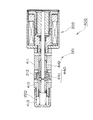
- FIG. 2 is a cross-sectional view of a solenoid valve 200 according to the present invention. As shown in FIG. 2, the solenoid valve 200 is formed by integrally connecting a control valve portion 201 and a solenoid portion 202.
- the control valve unit 201 includes a main body 210 as an outer frame and a valve space chamber 220 penetrating in the axial direction inside the main body 210.
- the valve space chamber 220 is divided into the first pressure chamber 221, the first valve chamber 222, the second valve chamber 223, and the second pressure chamber 224 by being divided by the first to third partitions 211 to 213. Is done.
- the main body 210 is made of a metal such as iron, brass, copper, aluminum, and stainless steel, a synthetic resin material such as industrial plastic and special resin.
- the main body 210 includes a discharge port 231 penetrating outward from the second pressure sensing chamber 224 in the axial direction, a supply port 232 penetrating from the outer peripheral surface to the first valve chamber 222, and from the outer peripheral surface to the second valve chamber 223.
- a penetrating output port 233 is formed.
- a plurality of supply ports 232 and output ports 233 are provided along the outer peripheral surface.
- a fluid having a supply pressure Po flows into the supply port 232, a fluid having a control pressure Pc flows out or flows into the output port 233, and a fluid having a discharge pressure Pd is discharged from the discharge port 231.
- the outer surface of the end portion of the main body 210 on the solenoid portion 202 side is formed on a mounting surface 214 to which the solenoid portion 202 is attached, and that end portion, that is, the end portion of the first pressure sensing chamber 221 on the solenoid portion 202 side is formed.
- a through hole 234 for the solenoid rod 286 that penetrates the end portion in the axial direction is provided.
- a peripheral surface of a hole communicating the first pressure sensing chamber 221 and the first valve chamber 222 of the first partitioning portion 211 of the main body 210 is formed on the first sliding surface 211A.
- An outer peripheral surface of a first pressure sensing portion 245 having a cylindrical shape of a valve body 240 described later is passed through the first sliding surface 211A with a slight clearance and is slid in the axial direction.
- a valve hole surface 212A is formed on the peripheral surface of the hole communicating with the first valve chamber 222 and the second valve chamber 223 of the second partition 212, and the end of the valve hole surface 212A on the first valve chamber 222 side is formed.
- the first valve seat surface 212B constituting the first poppet valve 203 is formed.
- the peripheral surface of the hole communicating the second valve chamber 223 and the second pressure sensing chamber 224 of the third partition 213 is formed on the second sliding surface 213A.
- the valve body 240 (corresponding to the first valve member in the claims) is formed with a cylindrical first pressure-sensitive portion 245 and a first valve body 242 at one end of a cylindrical body portion 241.
- the second valve body 243 is formed at the other end.
- the valve body 240 is a member in which the first valve body 242, the second valve body 243, and the first pressure sensing unit 245 are integrated.
- the valve body 240 is arranged such that the second partition 212 is interposed between the first valve body 242 and the second valve body 243 with the end on the first pressure sensing section 245 side facing the solenoid section 202 side. Thus, it is arranged in the valve space 220 of the main body 210 of the control valve unit 201.
- the valve body 240 is assembled, for example, by fitting the outer peripheral surface of the end portion of the body portion 241 to the fitting hole provided at the end portion of the first valve portion 242, and arranging the valve body 240 in the above arrangement. Is done.
- the material of the valve body 240 is, for example, a metal such as brass, copper, aluminum, or stainless steel, or a synthetic resin material.
- a first valve body 242 is disposed in the first valve chamber 222.
- the first valve body 242 is formed with a first valve portion surface 242A that is a tapered surface that has a smaller diameter toward the body portion 241, in other words, a smaller diameter toward the second partition portion 212 of the main body 210. ing.
- the first valve portion surface 242A joins with the first valve seat surface 212B and closes. Further, when the valve body 240 moves in a direction approaching the solenoid portion 202 and the tapered surface is separated from the first valve seat surface 212B, the valve is opened.
- the first valve portion surface 242A and the first valve seat surface 212B are configured as the first poppet valve 203 having a shape in which the cylindrical surface is not fitted. Since the poppet valve is such that the valve portion surface contacts (sits) with a slight width on the valve seat surface, sliding resistance can be avoided when the valve is opened and closed.
- the cross-sectional area (sitting area) of the inner diameter portion where the first valve portion surface 242A and the first valve seat surface 212B join (seat) is the first pressure receiving area S1 that receives the pressure of the working fluid.
- the body portion 241 of the valve body 240 is disposed loosely inside the valve hole surface 212 ⁇ / b> A of the second partition portion 212 of the main body 210.
- a gap between the body portion 241 of the valve body 240 and the valve hole surface 212A is formed in the first flow passage 225.
- the fluid having the supply pressure Po flows from the first valve chamber 222 through the first flow passage 225 and is supplied to the second valve chamber 223.
- the body portion 241 of the valve body 240 is disposed loosely inside the valve hole surface 212A of the second partition portion 212 of the main body 210.
- the body body 241 is moved even when the valve body 240 moves.
- a gap is secured between the portion 241 and the valve hole surface 212A, and these do not contact each other. Therefore, the movement of the valve body 240 is not accompanied by sliding resistance.
- the body 241 and the valve hole surface 212 ⁇ / b> A do not slide, so that the solenoid valve 200 does not malfunction.
- a second valve body 243 is disposed in the second valve chamber 223.
- the second valve body 243 is formed at the end of the valve body 240 opposite to the solenoid portion 202.
- the second valve body 243 is formed with a second valve portion surface 243A that is a tapered surface that has a smaller diameter toward the tip, in other words, a tapered surface that has a smaller diameter toward the valve seat body 250 described later.
- the second valve portion surface 243A is a bottomed cylinder in which the valve seat body 250 moves toward the valve body 240 and the tapered surface of the second valve body 243 is formed at the end of the valve seat body 250 on the valve body 240 side.
- valve hole surface 252A which is the inner peripheral surface of the valve seat portion 252 having a shape
- second valve seat surface 252B which is the annular inner peripheral corner portion of the opening portion of the cylindrical valve hole surface 252A.
- the second valve portion surface 243A and the second valve seat surface 252B are configured as the second poppet valve 204 having a shape in which the cylindrical surface does not fit.
- the second poppet valve 204 is such that the valve portion surface contacts (sits) with a minute width on the valve seat surface, and therefore does not involve sliding resistance when the valve is opened and closed.
- the cross-sectional area (sitting area) of the inner diameter portion where the second valve portion surface 243A and the second valve seat surface 252B are joined (seats) is the second pressure receiving area S2 that receives the pressure of the working fluid.
- a first communication passage 246 that penetrates from the first pressure sensing part 245 to the second valve body 243 is formed inside the valve body 240.
- a solenoid rod 286 passes through the first communication path 246 from the solenoid portion 202, and its end is connected to the end of the valve seat body 250 on the solenoid portion 202 side. Specifically, the end portion of the solenoid rod 286 is connected to the center portion of the bottom surface of the bottomed cylindrical valve seat portion 252 of the valve seat body 250.
- a first pressure sensing part 245 is formed on the solenoid part 202 side of the first valve body 242.
- the first pressure sensing part 245 extends from the end on the solenoid part 202 side of the first valve body 242 through the inside of the first partition part 211 to the first pressure sensing chamber 221,
- the aforementioned first communication path 246 is formed.
- the end of the first pressure-sensitive portion 245 on the solenoid portion 202 side is formed in a flange shape, and an end opening of the first communication passage 246 is formed in the center portion of the flange-shaped end surface.
- first spring 261 is installed in the periphery of the flange-shaped end face of the first pressure-sensitive portion 245.
- the other end of the first spring 261 is connected to the end face of the first pressure sensing chamber 221 on the solenoid part 202 side.
- the first spring 261 presses the valve body 240 in a direction opposite to the solenoid unit 202 by spring force F1.
- the fluid that has flowed into the first pressure sensing chamber 221 acts on each member in the communicating solenoid unit 202 to balance the pressure so that the fluid pressure does not act on only one surface (from the first pressure sensing chamber 221).
- the fluid also flows into the solenoid unit 202).
- the first pressure sensing chamber 221 is formed when the second valve portion surface 243A of the second valve body 243 of the valve body 240 is separated from the second valve seat surface 252B of the valve seat body 250 and the second poppet valve 204 is opened.
- the second valve chamber 223 communicates with the first communication passage 246.
- the second sense is obtained via the first communication passage 246. It communicates with the pressure chamber 224.
- the area where the first pressure sensing part 245 receives the supply pressure Po is a third pressure receiving area S3.
- a valve seat body 250 is disposed so as to be movable in the axial direction.
- the valve seat body 250 (corresponding to the second valve member in the claims) has a cylindrical valve seat portion 252 formed at the end of the cylindrical body portion 251 on the valve body 240 side.
- the end of the solenoid rod 286 is connected to the end on the valve body 240 side (solenoid part 202 side).
- the end of the valve seat body 250 opposite to the solenoid portion 202 is formed in a bottomed cylindrical shape that opens to the end portion side, and forms a second pressure-sensitive portion 255.
- a second spring 262 is installed inside the cylindrical second pressure-sensitive portion 255.
- the second spring 262 is an extension spring that biases the solenoid rod 286 toward the left side in the drawing, that is, the solenoid portion 202 side.
- the spring force of the second spring 262 is larger than the spring force of the first spring 261 described above, and when no magnetic force (F) is applied by the solenoid unit 202, the spring of the first spring 261 The valve seat body 250 and the valve body 240 are pushed toward the solenoid portion 202 by the spring force of the second spring 262 against the force.
- the pressure receiving area of the second pressure sensing unit 255 is a fourth pressure receiving area S4.
- the second valve seat surface 252 ⁇ / b> B provided at the inner peripheral corner of the valve seat 240 side end of the valve seat portion 252 of the valve seat body 250 is in contact with the second valve portion surface 243 ⁇ / b> A of the second valve body 243 of the valve body 240. Separates and forms an on-off valve.
- the second valve seat surface 252B and the second valve portion surface 243A constitute a second poppet valve 204 that has a small joining width and opens and closes.
- the area for receiving the fluid of the control pressure Pc in the cross section of the inner diameter portion where the second valve seat surface 252B and the second valve portion surface 243A are joined is the second pressure receiving area S2.
- the first pressure receiving area (the seating area of the first poppet valve 203) S1, the second pressure receiving area (the seating area of the second poppet valve 204) S2, the third pressure receiving area (the first pressure sensing part) described above.
- the pressure receiving area 245) S3 and the fourth pressure receiving area (the pressure receiving area of the second pressure sensing portion 255) S4 are both substantially equal.
- valve seat body 250 is formed with a second communication passage 256 that allows the bottom of the cylindrical valve seat portion 252 and the second pressure sensing chamber 224 to communicate with each other.
- the second communication passage 256 allows the fluid in the second valve chamber 223 to be introduced into the second pressure sensing chamber 224 in which the second spring 262 is disposed when the second poppet valve 204 is opened.
- the second communication passage 256 always communicates the second pressure sensing chamber 224 with the first communication passage 246, the first pressure sensing chamber 221 and the discharge port 231.
- the end opening on the valve body 240 side of the second communication passage 256 is formed at the center of the bottom surface of the bottomed cylindrical valve seat portion 252 of the valve seat body 250, but here as described above
- a solenoid rod 286 is connected to the first and second solenoid rods.
- a part of the opening of the second communication path 256 is further expanded to the outer peripheral portion than the outer diameter of the solenoid rod 286, or a groove is formed up to such a position.
- the opening is not closed by the rod 286, and the flow path is secured so that a sufficient fluid flow rate can be secured between the second valve chamber 223 and the second valve chamber 223.
- valve seat body 250 When the solenoid unit 202 is not operated by the valve seat body 250 having such a configuration, the valve seat body 250 is moved to the valve body 240 side by the spring force F2 of the second spring 262. When the valve seat body 250 moves, the valve seat body 250 moves to the right in the figure while closing with the valve body 240, and the first valve portion surface 242A is detached from the first valve seat surface 212B, and the first valve seat surface 212B is disengaged. 1 Poppet valve 203 is opened. At this time, the first spring 261 is also compressed.
- the configuration of the solenoid unit 202 is the same as the configuration of the solenoid unit 102, the description thereof is omitted.
- the operation of the solenoid valve 200 having such a configuration will be described.
- the magnetic force F of the solenoid unit 202 does not act, and the valve seat body 250 moves to the valve body 240 side by the extension force of the spring force F2 of the second spring 262.
- the second valve seat surface 252B of the valve seat body 250 is joined to the second valve portion surface 243A of the second valve body 243, and the second poppet valve 204 is brought into a closed state in which the stroke (opening amount) is zero.
- the stroke (opening amount) is zero.
- the second spring 262 further compresses the first spring 261 of the first pressure sensing chamber 221 while compressing the valve body 240. Is moved to the solenoid portion 202 side, the first valve portion surface 242A and the first valve seat surface 212B are separated from each other, and the first poppet valve 203 is in the open state with the maximum stroke (opening amount).
- the fluid having the supply pressure Po supplied from the supply port 232 flows through the first flow passage 225 between the first valve seat surface 212B and the first valve portion surface 242A and flows into the second valve chamber 223. .
- the flow rate of the control pressure Pc (for example, hydraulic brake) on the output port 233 side is increased. That is, the control pressure Pc can be increased when no current is supplied to the solenoid unit 102.
- the first valve portion surface 242A of the first valve body 242 forming the first poppet valve 203 is close to the first valve seat surface 212B.
- the stroke (opening amount) of the first poppet valve 203 becomes small.
- the magnetic force F, the movement positions of the valve body 240 and the valve seat body 250, and the stroke (opening amount) of the first poppet valve 203 are determined by the amount of current applied to the solenoid unit 202, as in the first embodiment. .
- the first valve portion surface 242A of the valve body 240 reaches a position where it is joined to the first valve seat surface 212B, and the stroke (opening amount) of the first poppet valve 203 is reached. Becomes zero and the valve is closed. In this state, the flow of fluid from the first valve chamber 222 to the second valve chamber 223 is interrupted, and the flow of fluid at the control pressure Pc from the supply port 232 to the output port 233 is stopped.
- the second poppet valve 204 is still in a closed state in which the stroke (opening amount) is zero, and the first poppet valve 203 and the second poppet valve 204 are also closed. Are closed together.
- valve body 240 cannot move in the direction of the valve seat body 250 because the first valve body 242 is already hooked by the second partition section 212.
- the valve seat body 250 directly connected to the solenoid rod 286 further moves in the direction opposite to the solenoid unit 202.
- the second valve seat surface 252B of the valve seat body 250 constituting the second poppet valve 204 is separated from the second valve portion surface 243A of the valve body 240, and the second poppet valve 204 is opened.
- the fluid having the control pressure Pc in the second valve chamber 223 is discharged to the discharge port 231 through the second communication passage 256 and the second pressure sensing chamber 224, and the control pressure Pc starts to decrease.
- the magnetic force F of the solenoid unit 202 is maximized, and the solenoid rod 286 moves the valve seat body 250 to the distal end of the solenoid unit 202.
- the second valve seat surface 252B of the valve seat portion 252 is separated from the second valve portion surface 243A of the second valve body 243, and the second poppet valve 204 is in the open state with the maximum stroke (opening amount).
- a fluid having a control pressure Pc for a hydraulic brake of an automatic transmission or the like can be discharged from the second valve chamber 223 to the discharge port 231 through the first communication passage 246 and the second pressure sensing chamber 224.
- the valve body 240 is pressed in the direction of the valve seat body 250 by the spring force F1 of the first spring 261, the first valve portion surface 242A is joined to the first valve seat surface 212B, and the first valve portion surface 242A
- the first poppet valve 203 composed of the first valve seat surface 212B is closed. For this reason, the fluid having the supply pressure Po supplied from the supply port 232 is blocked by the first poppet valve 203 and stopped flowing into the second valve chamber 223. That is, when a sufficient current is supplied to the solenoid unit 202, the control pressure Pc can be reduced.
- the solenoid valve 200 of this embodiment operates the solenoid rod 286 of the solenoid unit 202 according to the magnitude of the current, and cooperates with the spring forces F1 and F2 of the first and second springs 261 and 262. Then, the degree of opening and closing (opening amount) of the first poppet valve 203 and the second poppet valve 204 is controlled, and the flow rate is controlled by flowing a fluid of the control pressure Pc according to the degree of opening and closing of the valves.
- the solenoid rod 286 can be moved as set by only the magnetic force F of the solenoid unit 202 to control the degree of opening and closing of the first poppet valve 203 and the second poppet valve 204.
- the solenoid valve 200 is configured such that a sliding portion is not formed between the body portion 241 of the valve body 240 and the valve hole surface 212A of the second partition portion 212, as in the solenoid valve 100.
- the valve surfaces of the first poppet valve 203 and the second poppet 204 are narrow-width contacts that come into contact in a line contact state. Therefore, the first poppet valve 203 and the second poppet 204 can reduce the frictional resistance, and since there are few sliding surfaces, the possibility that the powder adheres between the sliding surfaces and increases the sliding resistance is reduced. be able to.
- valve portion by configuring the valve portion with a poppet valve, the amount of leakage in each valve can be reduced, and as a result, internal leakage of the entire valve can be reduced.
- the valve body slides with a slight clearance without using a bellows. Therefore, it is possible to prevent the tilt from occurring when the valve is seated due to the tilt of the bellows, and the valve can be appropriately opened and closed. Further, it is possible to configure a solenoid valve that can withstand high pressure as compared with the case of using a bellows. In other words, the flow rate can be ensured while the solenoid valve is small. Further, the cost of parts can be reduced, and the apparatus can be downsized.
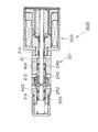
- the solenoid valve of this embodiment shows an example of a configuration in the case of actually realizing the normally closed solenoid valve according to the present invention schematically shown in FIG. Therefore, the solenoid valve 300 of the third embodiment shown in FIG. 3 has basically the same configuration as that of the solenoid valve 100 of the first embodiment, and substantially the same configuration is denoted by the same reference numeral for description. Omitted.
- the main body 310 is divided into a first main body portion 311, a second main body portion 312, and a third main body portion 313 in order from the solenoid portion 102 side for assembly reasons.
- a threaded portion is provided at the end, and the threaded portions are screwed together and assembled together.
- the second partition 112 that divides the valve space 120 is inserted between the male screw of the first main body portion 311 and the male screw of the second main body portion 312 and coupled to each other.
- the partition member 312 is sandwiched between the two and fixed.
- valve body 340 is configured as a combined body of the first valve portion 341 and the second valve portion 342.
- solenoid valve 300 Other configurations of the solenoid valve 300 are substantially the same as those of the solenoid valve 100 of the first embodiment.
- the operation, action, effect, etc. of the solenoid valve 300 are the same as those of the solenoid valve 100 of the first embodiment.
- the solenoid valve according to the present invention can be actually realized appropriately with such a configuration.
- the solenoid valve of this embodiment shows an example of a configuration in the case of actually realizing the normally open solenoid valve according to the present invention schematically shown in FIG. Therefore, the solenoid valve 400 of the fourth embodiment shown in FIG. 4 has basically the same configuration as that of the solenoid valve 200 of the second embodiment, and substantially the same configuration will be described with the same reference numerals. Omitted.
- the main body 410 is divided into a first main body portion 411, a second main body portion 412 and a third main body portion 413 in order from the solenoid portion 202 side for assembly reasons.
- a threaded portion is provided at the end, and the threaded portions are screwed together and assembled together.
- the second partition portion 212 that divides the valve space chamber 220 is inserted between the male screw of the first main body portion 411 and the male screw of the second main body portion 412.
- the partition member 412 is sandwiched and fixed.
- valve body 440 is configured as a combined body of the first valve portion 441 and the second valve portion 442.
- the solenoid valve of the present embodiment shows another configuration example in the case of actually realizing the normally closed solenoid valve according to the present invention schematically shown in FIG. Therefore, the solenoid valve 500 of the fifth embodiment shown in FIG. 5 has basically the same configuration as the solenoid valve 100 of the first embodiment and the solenoid valve 300 of the third embodiment, and is substantially the same configuration. Are denoted by the same reference numerals and description thereof is omitted.
- the solenoid valve 500 of the present embodiment is provided with an O-ring as a seal member on the sliding portion. That is, an O-ring 501 is disposed on the outer peripheral surface that slides with the first partitioning portion 111 of the first pressure-sensitive portion 145 of the valve body 140, and the third partitioning portion 113 of the second pressure-sensitive portion 155 of the valve seat body 150.
- the O-ring 502 is disposed on the outer peripheral surface that slides.
- the solenoid valve according to the present invention may be realized by such a configuration.
- Such an O-ring may be provided on the first partition portion 111 and the third partition portion 113 side, that is, on the main body 210 side.
- the solenoid valve of the present embodiment shows another configuration example in the case of actually realizing the normally open solenoid valve according to the present invention schematically shown in FIG. Therefore, the solenoid valve 600 of the sixth embodiment shown in FIG. 6 has basically the same configuration as the solenoid valve 200 of the second embodiment and the solenoid valve 400 of the fourth embodiment, and is substantially the same configuration. Are denoted by the same reference numerals and description thereof is omitted.
- the solenoid valve 600 of the present embodiment is provided with an O-ring as a seal member on the sliding portion. That is, an O-ring 601 is disposed on the outer peripheral surface that slides with the first partition portion 211 of the first pressure-sensitive portion 245 of the valve body 240, and the third partition portion 213 of the second pressure-sensitive portion 255 of the valve seat body 250. The O-ring 602 is disposed on the outer peripheral surface that slides.
- the solenoid valve according to the present invention may be realized by such a configuration.
- Such an O-ring may be provided on the first partition portion 211 and the third partition portion 213 side, that is, on the main body 210 side.
- the present invention is useful as a control valve that can accurately control the flow rate of a fluid supplied to a hydraulic system of a vehicle and a hydraulic / pneumatic system such as various power transmission devices. Further, it is useful as an inexpensive control valve, and further useful as a control valve without malfunction.
Landscapes
- Engineering & Computer Science (AREA)
- General Engineering & Computer Science (AREA)
- Mechanical Engineering (AREA)
- Magnetically Actuated Valves (AREA)
- Multiple-Way Valves (AREA)
Abstract
Description
日本国特許第3994871号公報に記載されている圧力比例制御弁は、入力ポートと出力ポートとの間に形成された連通室に配設された仕切板に設置される第1のポペット弁と、出力ポートに連通する連通室の入力ポートに連通する側とは反対側に設置される第2のポペット弁とを有し、仕切板の内周孔のシール摺動径(第1のポペット弁の弁体のシール摺動径、第1シール摺動径)と、第1のポペット弁の弁部の着座径と、第2のポペット弁の着座径(当接径)とを等しくすることにより、ソレノイドの出力に対して比例的に流体の圧力を制御することができるようにしたものである。
また、このような制御弁では、高圧に耐え得るソレノイドバルブを形成する場合にはベローズの耐圧性を上げる必要があり、ベローズの板厚を厚くする必要があるが、そのような構成にするとベローズのばね定数が大きくなり、ソレノイド全体を大きくする必要があるという課題が生じる。
また、ベローズを用いるこのような構成の制御弁では、ベローズの傾きに起因する弁の着座時の傾きを補正し切れない場合に、弁の開閉が適切にできない可能性もある。
内部が軸方向に貫通した弁空間室に形成され、当該弁空間室が内周径が周囲より細径に形成された第1仕切部、第2仕切部及び第3仕切部により軸方向に順に第1感圧室、第1弁室、第2弁室及び第2感圧室に仕切られた本体、
前記本体の前記第1弁室に貫通して前記本体の外部との間で所望の供給圧力の流体が流入出される供給ポート、
前記本体の前記第2弁室に貫通して前記本体の外部との間で所望の制御圧力の流体が流入出される出力ポート、
前記本体の前記第1感圧室又は前記第2感圧室の一方あるいは両方に各々貫通して前記本体の外部との間で所望の排出圧力の流体が流入出される排出ポート、
前記本体の前記第1感圧室、前記第1弁室及び前記第2弁室の内部に軸方向に移動自在に配置される部材であって、当該部材を軸方向に貫通し前記第1感圧室側と前記第2弁室側とを連通する第1連通路を内部に有する第1弁部材、
前記第2弁室及び前記第2感圧室の内部に軸方向に移動自在に配置される部材であって、当該部材を軸方向に貫通し前記第2弁室側と前記第2感圧室側とを連通する第2連通路を内部に有する第2弁部材、
前記第1弁室と前記第2弁室を仕切る前記第2仕切部に形成される弁体又は弁座体のいずれか一方と、前記第1弁部材に形成される前記弁体又は弁座体のいずれか他方とを有し、前記供給ポートを介して流体が流される前記第1弁室と前記出力ポートを介して流体が流される前記第2弁室との間を開閉する第1ポペット弁、
前記第1弁部材の前記第2弁室側の端部であって当該第2弁室内に形成される弁体又は弁座体のいずれか一方と、前記第2弁部材の前記第2弁室側の端部であって当該第2弁室内に形成される弁体又は弁座体のいずれか他方とを有し、開弁状態においては前記第1連通路及び前記第2連通路と当該第2弁室とを連通し、閉弁状態においては前記第1連通路と前記第2連通路とを連通させる第2ポペット弁、
前記第1弁部材に一体に形成され、前記第1感圧室と前記第1弁室を仕切る前記第1仕切部の内周に摺動可能に配置される第1感圧部、
前記第2弁部材に一体に形成され、前記第2弁室と前記第2感圧室とを仕切る前記第3仕切部の内周に摺動可能に配置される第2感圧部、
印加される電流に応じて所定方向の磁力を発生し、当該磁力を前記第2弁部材に連結されたソレノイドロッドを介して前記第2弁部材に作用させるソレノイド部、
前記本体と第1弁部材との間に設置され前記第1弁部材に前記第2弁部材方向の弾性力を作用させる第1スプリング、及び
前記本体と第2弁部材との間に設置され前記第2弁部材に前記ソレノイド部により作用される磁力と反対方向の弾性力を作用させる第2スプリングを有し、
前記第1ポペット弁の着座面積である第1受圧面積と、前記第2ポペット弁の着座面積である第2受圧面積と、前記第1感圧部の受圧面積である第3受圧面積と、前記第2感圧部の受圧面積である第4受圧面積とをほぼ等しくしたことを特徴とする。
本発明の第1実施形態について図1を参照して説明する。
本実施形態においては、本発明に係るノーマルクローズ型のソレノイドバルブの基本的な構成について図1を参照して説明する。本実施形態のソレノイドバルブは、例えばオートマチックトランスミッションの油圧ブレーキ等の用途に用いられるものである。
図1は、本発明に係るソレノイドバルブ100の断面図である。
図1に示すように、ソレノイドバルブ100は、制御弁部101とソレノイド部102とを結合して一体に形成したものである。
なお、本体110は、鉄、真鍮、銅、アルミニウム、ステンレス等の金属、工業プラスチック、特殊樹脂等の合成樹脂材で製作される。
本体110の第1仕切部111の第1感圧室121と第1弁室122とを連通する孔の周面は、第1摺動面111Aに形成されている。第1摺動面111Aには、後述する弁体140の円筒形状を有する第1感圧部145の外周面が僅かなクリアランスを持って貫通され、軸方向に摺動される。
なお、弁体140は、例えば、第1弁部142の端部に設けた嵌合孔に胴体部141の端部外周面を嵌着して連結する等して組み立てられ、上記の配置に配される。
弁体140の材質は、例えば、真鍮、銅、アルミニウム、ステンレス等の金属、あるいは合成樹脂材等である。
なお、第1弁部面142Aと第1弁座面112Bとが接合する(着座する)内径部分の断面積(着座面積)は、作動流体の圧力を受ける第1受圧面積S1となる。
なお、第2弁部面143Aと第2弁座面152Bとが接合する(着座する)内径部分の断面積(着座面積)は、作動流体の圧力を受ける第2受圧面積S2となる。
なお、第1感圧部145が供給圧力Poを受ける面積は、第3受圧面積S3である。
弁座体150(特許請求の範囲における第2弁部材に相当する。)は、円柱状の胴体部151の弁体140側の端部に筒状の弁座部152が形成され、胴体部151のソレノイド部102側に第2感圧部155が形成されている。また、弁座体150のさらにソレノイド部102側の端部には、ソレノイドロッド186の端部が連結されている。また、弁座体150のソレノイド部102側の端部は、外径方向にフランジ部153が形成されており、フランジ部153と第3仕切部113のソレノイド部102側の環状側面との間に第2のスプリング162が設置されている。第2のスプリング162はソレノイドロッド186を図示右側、すなわちソレノイド部102側に付勢する伸長ばねである。
なお、第2感圧部155の受圧面積は、第4受圧面積S4である。
本実施形態においては、前述した第1受圧面積(第1ポペット弁103の着座面積)S1、第2受圧面積(第2ポペット弁104の着座面積)S2、第3受圧面積(第1感圧部145の受圧面積)S3及び第4受圧面積(第2感圧部155の受圧面積)S4は、いずれもほぼ等しく形成する。なお、ほぼ等しいとは、±6%の範囲内であれば、ほぼ同一の作用効果が達せられる。
第2感圧室124に流入した流体は、連通するソレノイド部102内の各部材に作用して流体の圧力が一方の面にのみ作用しないように圧力をバランスさせる(第2感圧室124からソレノイド部102の内部にも流体は流入する)。
ソレノイド部102は、内部に可動芯181を設けるとともに、可動芯181にはソレノイドロッド186を結合する。また、可動芯181の対向した位置には固定芯182を設け、可動芯181と固定芯182の周囲には電磁コイル183を配置して電磁回路を構成する。この電磁コイル183に電流が印可されると、その電流の大きさに応じて電磁回路に発生する磁力Fにより、可動芯181は固定芯182に吸引される。可動芯181が固定芯182に吸引されると、可動芯181と一体のソレノイドロッド186は可動芯181とともに移動して、第2のスプリング162を圧縮させながら弁座体150を押圧する。弁座体150が移動すると、弁座体150は弁体140と閉弁しながら弁体140を図示左方へ移動させ、第1弁部面142Aを第1弁座面112Bから離脱させて第1ポペット弁103を開弁する。このとき、第1のスプリング161も圧縮される。
まず、ソレノイド部102に電流が印加されていない状態においては、ソレノイド部102の可動芯181と固定芯182との間には磁力Fは作用せず、可動芯181と固定芯182とは離間した状態になり、弁座体150は、第2のスプリング162のばね力F2の伸長力によりソレノイド部102側へ押動された状態となる。その結果、弁座部152の第2弁座面152Bは弁体140の第2弁部面143Aから離間して、第2ポペット弁104はストローク(開口量)が最大の開弁状態となる。
また、第2ポペット弁104が開弁状態のときは、弁体140は、第1感圧室121に配置される第1のスプリング161のばね力F1により押圧され、第1弁部面142Aが第1弁座面112Bと接合した状態とされる。すなわち、第1弁部面142Aと第1弁座面112Bからなる第1ポペット弁103は、ストローク(開口量)がゼロの閉弁状態となる。このため、供給ポート132から供給される供給圧力Poの流体は、第1ポペット弁103により遮断され、第2弁室123への流入は停止される。
なお、この状態、すなわち弁座体150が単に第2弁座面152Bが第2弁部面143Aに接合する位置に移動した状態においては、第1ポペット弁103も未だストローク(開口量)がゼロの閉弁状態であり、第1ポペット弁103及び第2ポペット弁104が共に閉じた状態となる。
この状態においては、前述したように第2弁座面152Bが第2弁部面143Aに接合し第2ポペット弁104が閉じた状態なので、第2弁室123と第1連通路146との流体の流れは遮断され、出力ポート133を流れる制御圧力Pcの流体の排出ポート131側への流出は停止される。
第1のスプリング161と第2のスプリング162のばね力F1,F2とソレノイド部102の磁力Fにより制御された可動芯181は、固定芯182との距離が制御されるから、可動芯181と一体のソレノイドロット186も制御されて所望の距離だけ移動される。
また、ベローズを使用する場合と比較して高圧に耐え得るソレノイドバルブを構成することができる。換言すれば、ソレノイドバルブを小型の状態で、流量を確保することができる。
また、部品コストを低減することができ、装置を小型化することも可能となる。
本発明の第2実施形態について図2を参照して説明する。
本実施形態においては、本発明に係るノーマルオープン型のソレノイドバルブの基本的な構成について図2を参照して説明する。本実施形態のソレノイドバルブも、第1実施形態と同様に、例えばオートマチックトランスミッションの油圧ブレーキ等の用途に用いられるものである。
図2に示すように、ソレノイドバルブ200は、制御弁部201とソレノイド部202とを結合して一体に形成したものである。
なお、本体210は、鉄、真鍮、銅、アルミニウム、ステンレス等の金属、工業プラスチック、特殊樹脂等の合成樹脂材で製作される。
なお、弁体240は、例えば、第1弁部242の端部に設けた嵌合孔に胴体部241の端部外周面を嵌着して連結する等して組み立てられ、上記の配置に配される。
弁体240の材質は、例えば、真鍮、銅、アルミニウム、ステンレス等の金属、あるいは合成樹脂材等である。
なお、第1弁部面242Aと第1弁座面212Bとが接合する(着座する)内径部分の断面積(着座面積)は、作動流体の圧力を受ける第1受圧面積S1となる。
なお、第2弁部面243Aと第2弁座面252Bとが接合する(着座する)内径部分の断面積(着座面積)は、作動流体の圧力を受ける第2受圧面積S2となる。
なお、第1感圧部245が供給圧力Poを受ける面積は、第3受圧面積S3である。
弁座体250(特許請求の範囲における第2弁部材に相当する。)は、円柱状の胴体部251の弁体240側の端部に筒状の弁座部252が形成され、また、その弁体240側(ソレノイド部202側)の端部にソレノイドロッド286の端部が連結されている。また、弁座体250のソレノイド部202とは反対側の端部は、その端部側に開口した有底円筒形状に形成されており、第2感圧部255を形成している。その、円筒形状の第2感圧部255の内側に、第2のスプリング262が設置されている。第2のスプリング262はソレノイドロッド286を図示左側、すなわちソレノイド部202側に付勢する伸長ばねである。
なお、第2感圧部255の受圧面積は、第4受圧面積S4である。
本実施形態においては、前述した第1受圧面積(第1ポペット弁203の着座面積)S1、第2受圧面積(第2ポペット弁204の着座面積)S2、第3受圧面積(第1感圧部245の受圧面積)S3及び第4受圧面積(第2感圧部255の受圧面積)S4は、いずれもほぼ等しく形成する。
なお、第2連通路256の弁体240側の端部開口は、弁座体250の有底円筒形状の弁座部252の底面の中央部に形成されているが、ここには前述したようにソレノイドロッド286が連結されている。しかし第2連通路256の開口部は、図2に示すように、その一部がソレノイドロッド286の外径よりもさらに外周部に拡径され、あるいはそのような位置まで溝が形成され、ソレノイドロッド286により開口が閉塞されず、第2弁室223との間で十分な流体の流量が確保できるようにその流路が確保されている。
ソレノイド部202に電流が印加されていない状態において、ソレノイド部202の磁力Fは作用せず、弁座体250は、第2のスプリング262のばね力F2の伸長力により、弁体240側へ移動し、弁座体250の第2弁座面252Bが第2弁体243の第2弁部面243Aと接合して第2ポペット弁204をストローク(開口量)がゼロの閉弁状態にする。その結果、第2弁室223と第2連通路256との流体の流れは遮断され、出力ポート233を流れる制御圧力Pcの流体は、排出ポート231側へ流出させることができなくなる。
つまり、ソレノイド部102へ電流が流されないときに、制御圧力Pcを増大させることができる。
一方で、第2ポペット弁204がソレノイド部202から離れる方向に移動することで、第1ポペット弁203を形成する第1弁体242の第1弁部面242Aは第1弁座面212Bに近接し、第1ポペット弁203のストローク(開口量)は小さくなる。
なお、この第1ポペット弁203が閉弁した直後の状態においては、第2ポペット弁204も未だストローク(開口量)がゼロの閉弁状態であり、第1ポペット弁203及び第2ポペット弁204が共に閉じた状態となる。
つまり、ソレノイド部202への十分な電流が流されると、制御圧力Pcを低下させることができる。
また、ベローズを使用する場合と比較して高圧に耐え得るソレノイドバルブを構成することができる。換言すれば、ソレノイドバルブを小型の状態で、流量を確保することができる。
また、部品コストを低減することができ、装置を小型化することも可能となる。
本発明の第3実施形態について図3を参照して説明する。
本実施形態のソレノイドバルブは、図1に模式的に示した本発明に係るノーマルクローズ型のソレノイドバルブを実際に実現する場合の一構成例を示したものである。
従って、図3に示す第3実施形態のソレノイドバルブ300は、基本的に第1実施形態のソレノイドバルブ100と同じ構成であり、実質的に同一の構成については同一の符号を付して説明を省略する。
本発明に係るソレノイドバルブは、このような構成とすることで実際に適切に実現することができる。
本発明の第4実施形態について図4を参照して説明する。
本実施形態のソレノイドバルブは、図2に模式的に示した本発明に係るノーマルオープン型のソレノイドバルブを実際に実現する場合の一構成例を示したものである。
従って、図4に示す第4実施形態のソレノイドバルブ400は、基本的に第2実施形態のソレノイドバルブ200と同じ構成であり、実質的に同一の構成については同一の符号を付して説明を省略する。
本発明に係るソレノイドバルブは、このような構成とすることで実際に適切に実現することができる。
本発明の第5実施形態について図5を参照して説明する。
本実施形態のソレノイドバルブは、図1に模式的に示した本発明に係るノーマルクローズ型のソレノイドバルブを実際に実現する場合の他の構成例を示したものである。
従って、図5に示す第5実施形態のソレノイドバルブ500は、基本的に第1実施形態のソレノイドバルブ100、及び、第3実施形態のソレノイドバルブ300と同じ構成であり、実質的に同一の構成については同一の符号を付して説明を省略する。
本発明に係るソレノイドバルブは、このような構成により実現してもよい。
なお、このようなOリングは、第1仕切部111及び第3仕切部113側、すなわち本体210側に設けるようにしてもよい。また、Oリング以外の任意のシール部材を用いるようにしてもよい。
本発明の第6実施形態について図6を参照して説明する。
本実施形態のソレノイドバルブは、図2に模式的に示した本発明に係るノーマルオープン型のソレノイドバルブを実際に実現する場合の他の構成例を示したものである。
従って、図6に示す第6実施形態のソレノイドバルブ600は、基本的に第2実施形態のソレノイドバルブ200、及び、第4実施形態のソレノイドバルブ400と同じ構成であり、実質的に同一の構成については同一の符号を付して説明を省略する。
本発明に係るソレノイドバルブは、このような構成により実現してもよい。
なお、このようなOリングは、第1仕切部211及び第3仕切部213側、すなわち本体210側に設けるようにしてもよい。また、Oリング以外の任意のシール部材を用いるようにしてもよい。
Claims (2)
- 流体の流量を制御するソレノイドバルブであって、
内部が軸方向に貫通した弁空間室に形成され、当該弁空間室が細径に形成された第1仕切部、第2仕切部及び第3仕切部により順に第1感圧室、第1弁室、第2弁室及び第2感圧室に仕切られた本体、
前記第1弁室に貫通して流体が流入出される供給ポート、
前記第2弁室に貫通して流体が流入出される出力ポート、
前記第1感圧室又は前記第2感圧室の一方あるいは両方に各々貫通して流体が流入出される排出ポート、
前記第1感圧室、前記第1弁室及び前記第2弁室の内部に軸方向に移動自在に配置され、内部に軸方向に貫通し前記第1感圧室側と前記第2弁室側とを連通する第1連通路を有する第1弁部材、
前記第2弁室及び前記第2感圧室の内部に軸方向に移動自在に配置され、内部に軸方向に貫通し前記第2弁室側と前記第2感圧室側とを連通する第2連通路を有する第2弁部材、
前記第1弁室と前記第2弁室を仕切る前記第2仕切部に形成される弁体又は弁座体のいずれか一方と、前記第1弁部材に形成される前記弁体又は弁座体のいずれか他方とを有し、前記第1弁室と前記第2弁室との間を開閉する第1ポペット弁、
前記第1弁部材の前記第2弁室側の端部に形成される弁体又は弁座体のいずれか一方と、前記第2弁部材の前記第2弁室側の端部に形成される弁体又は弁座体のいずれか他方とを有し、開弁状態においては前記第1連通路及び前記第2連通路と当該第2弁室とを連通し、閉弁状態においては前記第1連通路と前記第2連通路とを連通させる第2ポペット弁、
前記第1弁部材に一体に形成され、前記第1感圧室と前記第1弁室を仕切る前記第1仕切部の内周に摺動可能に配置される第1感圧部、
前記第2弁部材に一体に形成され、前記第2弁室と前記第2感圧室とを仕切る前記第3仕切部の内周に摺動可能に配置される第2感圧部、
印加される電流に応じて所定方向の磁力を発生し、当該磁力を前記第2弁部材に連結されたソレノイドロッドを介して前記第2弁部材に作用させるソレノイド部、
前記第1弁部材に前記第2弁部材方向の弾性力を作用させる第1スプリング、及び
前記第2弁部材に前記ソレノイド部により作用される磁力と反対方向の弾性力を作用させる第2スプリングを有し、
前記第1ポペット弁の着座面積である第1受圧面積と、前記第2ポペット弁の着座面積である第2受圧面積と、前記第1感圧部の受圧面積である第3受圧面積と、前記第2感圧部の受圧面積である第4受圧面積とをほぼ等しくしたことを特徴とするソレノイドバルブ。 - 前記第1仕切部及び前記第3仕切部の少なくともいずれか一方において、当該仕切部の内周と、当該内周と摺動する前記第1感圧部又は前記第2感圧部の外周とのいずれか一方又は両方に、シール部材が配設されていることを特徴とする請求項1に記載のソレノイドバルブ。
Priority Applications (4)
| Application Number | Priority Date | Filing Date | Title |
|---|---|---|---|
| EP11750533.9A EP2543915B1 (en) | 2010-03-03 | 2011-02-23 | Solenoid valve |
| US13/503,996 US8931517B2 (en) | 2010-03-03 | 2011-02-23 | Solenoid valve |
| CN201180012104.9A CN102782379B (zh) | 2010-03-03 | 2011-02-23 | 电磁阀 |
| JP2012503086A JP5687267B2 (ja) | 2010-03-03 | 2011-02-23 | ソレノイドバルブ |
Applications Claiming Priority (2)
| Application Number | Priority Date | Filing Date | Title |
|---|---|---|---|
| JP2010-046395 | 2010-03-03 | ||
| JP2010046395 | 2010-03-03 |
Publications (1)
| Publication Number | Publication Date |
|---|---|
| WO2011108423A1 true WO2011108423A1 (ja) | 2011-09-09 |
Family
ID=44542077
Family Applications (1)
| Application Number | Title | Priority Date | Filing Date |
|---|---|---|---|
| PCT/JP2011/054012 Ceased WO2011108423A1 (ja) | 2010-03-03 | 2011-02-23 | ソレノイドバルブ |
Country Status (5)
| Country | Link |
|---|---|
| US (1) | US8931517B2 (ja) |
| EP (1) | EP2543915B1 (ja) |
| JP (1) | JP5687267B2 (ja) |
| CN (1) | CN102782379B (ja) |
| WO (1) | WO2011108423A1 (ja) |
Cited By (2)
| Publication number | Priority date | Publication date | Assignee | Title |
|---|---|---|---|---|
| CN102563092A (zh) * | 2011-12-17 | 2012-07-11 | 西安航空动力控制有限责任公司 | 一种高压力常闭型开关电磁阀 |
| CN102720879A (zh) * | 2012-06-25 | 2012-10-10 | 长城汽车股份有限公司 | 一种电磁阀及自动变速器的液压控制系统 |
Families Citing this family (38)
| Publication number | Priority date | Publication date | Assignee | Title |
|---|---|---|---|---|
| KR101158423B1 (ko) * | 2010-05-26 | 2012-06-22 | 주식회사 케피코 | 차량의 자동변속기용 유압 솔레노이드 밸브 |
| CN103195946B (zh) * | 2013-03-04 | 2014-12-17 | 宁波长壁流体动力科技有限公司 | 先导阀 |
| JP2015145725A (ja) * | 2014-01-31 | 2015-08-13 | ボーグワーナー インコーポレーテッド | ラッチソレノイドレギュレータ弁 |
| US9791062B2 (en) * | 2014-10-13 | 2017-10-17 | Fema Corporation Of Michigan | Hydraulic valve having pressure compensated flow control |
| US10612676B2 (en) * | 2016-01-14 | 2020-04-07 | Do Qoom, Corp, Ltd | Check valve having reverse-direction fluid supply function |
| US10781804B2 (en) * | 2016-08-29 | 2020-09-22 | Eagle Industry Co., Ltd. | Displacement control valve |
| EP3575647B1 (en) | 2017-01-26 | 2022-11-30 | Eagle Industry Co., Ltd. | Capacity control valve |
| EP3584441B1 (en) | 2017-02-18 | 2022-08-31 | Eagle Industry Co., Ltd. | Capacity control valve |
| CN110325479B (zh) | 2017-02-24 | 2022-09-06 | 默克专利股份公司 | 水净化和施配系统及方法 |
| DE102017208310B4 (de) * | 2017-05-17 | 2023-02-16 | Mando Corporation | Ventilanordnung und diese Ventilanordnung enthaltendes Antiblockiersystem |
| EP3650695B1 (en) * | 2017-07-05 | 2023-09-06 | Eagle Industry Co., Ltd. | Capacity control valve |
| US11359625B2 (en) | 2017-07-06 | 2022-06-14 | Eagle Industry Co., Ltd. | Capacity control valve having an auxiliary communication part allowing communication with an intermediate passage |
| CN114687984B (zh) | 2017-11-15 | 2024-12-31 | 伊格尔工业股份有限公司 | 容量控制阀 |
| EP3719364B1 (en) | 2017-11-30 | 2023-11-15 | Eagle Industry Co., Ltd. | Capacity control valve and control method for capacity control valve |
| KR102441855B1 (ko) | 2017-12-08 | 2022-09-08 | 이구루코교 가부시기가이샤 | 용량 제어 밸브 및 용량 제어 밸브의 제어 방법 |
| CN111417780B (zh) | 2017-12-14 | 2022-05-17 | 伊格尔工业股份有限公司 | 容量控制阀及容量控制阀的控制方法 |
| US11454227B2 (en) | 2018-01-22 | 2022-09-27 | Eagle Industry Co., Ltd. | Capacity control valve |
| US11187330B2 (en) * | 2018-04-17 | 2021-11-30 | Hydraforce, Inc. | Hydraulic balancing control valve and ride control system incorporating same |
| US11339807B2 (en) * | 2018-05-10 | 2022-05-24 | Shimadzu Corporation | Priority flow control valve |
| CN113015853B (zh) | 2018-11-26 | 2022-12-23 | 伊格尔工业股份有限公司 | 容量控制阀 |
| US11035482B2 (en) * | 2019-01-31 | 2021-06-15 | Scott Dale Follett | Pressure relief valve |
| JP7127850B2 (ja) * | 2019-09-19 | 2022-08-30 | 株式会社不二工機 | 流路切換弁 |
| CN110630805B (zh) * | 2019-09-26 | 2021-01-01 | 长安大学 | 一种航空发动机快速电磁阀系统及其控制方法 |
| JP2021125633A (ja) * | 2020-02-07 | 2021-08-30 | 日本電産コパル電子株式会社 | プランジャとその製造方法 |
| WO2022030309A1 (ja) | 2020-08-03 | 2022-02-10 | イーグル工業株式会社 | 弁 |
| EP4194725B1 (en) | 2020-08-04 | 2025-11-19 | Eagle Industry Co., Ltd. | Valve |
| CN116157609A (zh) | 2020-08-04 | 2023-05-23 | 伊格尔工业股份有限公司 | 阀 |
| US12298048B2 (en) | 2020-08-04 | 2025-05-13 | Eagle Industry Co., Ltd. | Expansion valve |
| CN116097026B (zh) | 2020-08-24 | 2025-11-11 | 伊格尔工业股份有限公司 | 阀 |
| KR102879499B1 (ko) | 2020-09-28 | 2025-10-31 | 이구루코교 가부시기가이샤 | 밸브 |
| EP4224032B1 (en) | 2020-10-01 | 2025-12-10 | Eagle Industry Co., Ltd. | Valve |
| EP4224047A4 (en) | 2020-10-01 | 2024-10-23 | Eagle Industry Co., Ltd. | FLUID CONTROL VALVE |
| JP7826229B2 (ja) | 2020-12-17 | 2026-03-09 | イーグル工業株式会社 | 弁 |
| JP7780506B2 (ja) | 2021-03-29 | 2025-12-04 | イーグル工業株式会社 | 弁 |
| US12435794B2 (en) | 2021-05-31 | 2025-10-07 | Eagle Industry Co., Ltd. | Fluid control valve |
| JPWO2023033143A1 (ja) | 2021-09-02 | 2023-03-09 | ||
| CN115405710B (zh) * | 2022-09-01 | 2023-06-09 | 唐山传奇科技有限公司 | 自闭式高速泄压阀 |
| CN118815955B (zh) * | 2024-08-28 | 2026-02-03 | 河南航天液压气动技术有限公司 | 一种两位三通电磁阀 |
Citations (5)
| Publication number | Priority date | Publication date | Assignee | Title |
|---|---|---|---|---|
| US3016917A (en) * | 1956-08-24 | 1962-01-16 | Int Basic Economy Corp | Valve for controlling pressurized fluid |
| JPS6436777U (ja) * | 1987-08-28 | 1989-03-06 | ||
| JP2004197858A (ja) * | 2002-12-19 | 2004-07-15 | Isuzu Motors Ltd | 圧力比例制御弁 |
| WO2009025366A1 (ja) | 2007-08-23 | 2009-02-26 | Eagle Industry Co., Ltd. | 制御弁 |
| JP2009287613A (ja) * | 2008-05-27 | 2009-12-10 | Keihin Corp | 電磁スプール弁装置 |
Family Cites Families (6)
| Publication number | Priority date | Publication date | Assignee | Title |
|---|---|---|---|---|
| US5123718A (en) * | 1990-04-06 | 1992-06-23 | G. W. Lisk Company, Inc. | Valve for automatic brake system |
| JP3921828B2 (ja) * | 1998-08-05 | 2007-05-30 | いすゞ自動車株式会社 | 電磁弁 |
| AU2003207057A1 (en) * | 2003-02-12 | 2004-09-06 | Isuzu Motors Limited | Flow control valve |
| CN101410620B (zh) * | 2006-03-15 | 2011-03-23 | 伊格尔工业股份有限公司 | 容量控制阀 |
| JP5217038B2 (ja) * | 2007-08-23 | 2013-06-19 | イーグル工業株式会社 | 制御弁 |
| WO2009028534A1 (ja) * | 2007-08-31 | 2009-03-05 | Eagle Industry Co., Ltd. | 制御弁 |
-
2011
- 2011-02-23 US US13/503,996 patent/US8931517B2/en active Active
- 2011-02-23 EP EP11750533.9A patent/EP2543915B1/en active Active
- 2011-02-23 CN CN201180012104.9A patent/CN102782379B/zh active Active
- 2011-02-23 WO PCT/JP2011/054012 patent/WO2011108423A1/ja not_active Ceased
- 2011-02-23 JP JP2012503086A patent/JP5687267B2/ja active Active
Patent Citations (6)
| Publication number | Priority date | Publication date | Assignee | Title |
|---|---|---|---|---|
| US3016917A (en) * | 1956-08-24 | 1962-01-16 | Int Basic Economy Corp | Valve for controlling pressurized fluid |
| JPS6436777U (ja) * | 1987-08-28 | 1989-03-06 | ||
| JP2004197858A (ja) * | 2002-12-19 | 2004-07-15 | Isuzu Motors Ltd | 圧力比例制御弁 |
| JP3994871B2 (ja) | 2002-12-19 | 2007-10-24 | いすゞ自動車株式会社 | 圧力比例制御弁 |
| WO2009025366A1 (ja) | 2007-08-23 | 2009-02-26 | Eagle Industry Co., Ltd. | 制御弁 |
| JP2009287613A (ja) * | 2008-05-27 | 2009-12-10 | Keihin Corp | 電磁スプール弁装置 |
Cited By (3)
| Publication number | Priority date | Publication date | Assignee | Title |
|---|---|---|---|---|
| CN102563092A (zh) * | 2011-12-17 | 2012-07-11 | 西安航空动力控制有限责任公司 | 一种高压力常闭型开关电磁阀 |
| CN102720879A (zh) * | 2012-06-25 | 2012-10-10 | 长城汽车股份有限公司 | 一种电磁阀及自动变速器的液压控制系统 |
| CN102720879B (zh) * | 2012-06-25 | 2014-09-03 | 长城汽车股份有限公司 | 一种电磁阀及自动变速器的液压控制系统 |
Also Published As
| Publication number | Publication date |
|---|---|
| CN102782379B (zh) | 2014-02-26 |
| US20120211686A1 (en) | 2012-08-23 |
| JPWO2011108423A1 (ja) | 2013-06-27 |
| EP2543915A4 (en) | 2016-07-20 |
| EP2543915B1 (en) | 2018-04-11 |
| JP5687267B2 (ja) | 2015-03-18 |
| EP2543915A1 (en) | 2013-01-09 |
| US8931517B2 (en) | 2015-01-13 |
| CN102782379A (zh) | 2012-11-14 |
Similar Documents
| Publication | Publication Date | Title |
|---|---|---|
| JP5687267B2 (ja) | ソレノイドバルブ | |
| US8434517B2 (en) | Control valve | |
| JP5211349B2 (ja) | 制御弁 | |
| US8434518B2 (en) | Control valve | |
| US8931758B2 (en) | Solenoid valve | |
| KR101723128B1 (ko) | 밸브 부재 단부를 밀봉하기 위한 다이어프램을 구비한 압력 평형 밸브 | |
| US20130255809A1 (en) | Valve, In Particular Pilot-Operated Proportional Pressure Control Valve | |
| EP3129660A1 (en) | Servo valve | |
| JP6088591B2 (ja) | ソレノイドバルブ | |
| US20190145540A1 (en) | Solenoid valve | |
| US11125344B1 (en) | Valve having a spool with fluid jet separation features | |
| US10215200B2 (en) | Electrohydraulic control valve | |
| US20190040970A1 (en) | Composite valve and solenoid valve using the same | |
| HK1152738A1 (en) | Balanced solenoid valve | |
| HK1152738B (en) | Balanced solenoid valve |
Legal Events
| Date | Code | Title | Description |
|---|---|---|---|
| WWE | Wipo information: entry into national phase |
Ref document number: 201180012104.9 Country of ref document: CN |
|
| 121 | Ep: the epo has been informed by wipo that ep was designated in this application |
Ref document number: 11750533 Country of ref document: EP Kind code of ref document: A1 |
|
| WWE | Wipo information: entry into national phase |
Ref document number: 2012503086 Country of ref document: JP |
|
| WWE | Wipo information: entry into national phase |
Ref document number: 13503996 Country of ref document: US |
|
| WWE | Wipo information: entry into national phase |
Ref document number: 2011750533 Country of ref document: EP |
|
| NENP | Non-entry into the national phase |
Ref country code: DE |