WO2011108726A1 - モータケースに設置されたインバータ端子台 - Google Patents
モータケースに設置されたインバータ端子台 Download PDFInfo
- Publication number
- WO2011108726A1 WO2011108726A1 PCT/JP2011/055130 JP2011055130W WO2011108726A1 WO 2011108726 A1 WO2011108726 A1 WO 2011108726A1 JP 2011055130 W JP2011055130 W JP 2011055130W WO 2011108726 A1 WO2011108726 A1 WO 2011108726A1
- Authority
- WO
- WIPO (PCT)
- Prior art keywords
- inverter
- motor
- terminal
- case
- side connection
- Prior art date
- Legal status (The legal status is an assumption and is not a legal conclusion. Google has not performed a legal analysis and makes no representation as to the accuracy of the status listed.)
- Ceased
Links
Images

Classifications
-
- H—ELECTRICITY
- H02—GENERATION; CONVERSION OR DISTRIBUTION OF ELECTRIC POWER
- H02K—DYNAMO-ELECTRIC MACHINES
- H02K11/00—Structural association of dynamo-electric machines with electric components or with devices for shielding, monitoring or protection
- H02K11/0094—Structural association with other electrical or electronic devices
-
- H—ELECTRICITY
- H01—ELECTRIC ELEMENTS
- H01R—ELECTRICALLY-CONDUCTIVE CONNECTIONS; STRUCTURAL ASSOCIATIONS OF A PLURALITY OF MUTUALLY-INSULATED ELECTRICAL CONNECTING ELEMENTS; COUPLING DEVICES; CURRENT COLLECTORS
- H01R13/00—Details of coupling devices of the kinds covered by groups H01R12/70 or H01R24/00 - H01R33/00
- H01R13/46—Bases; Cases
- H01R13/52—Dustproof, splashproof, drip-proof, waterproof, or flameproof cases
- H01R13/5202—Sealing means between parts of housing or between housing part and a wall, e.g. sealing rings
-
- H—ELECTRICITY
- H02—GENERATION; CONVERSION OR DISTRIBUTION OF ELECTRIC POWER
- H02K—DYNAMO-ELECTRIC MACHINES
- H02K11/00—Structural association of dynamo-electric machines with electric components or with devices for shielding, monitoring or protection
- H02K11/30—Structural association with control circuits or drive circuits
- H02K11/33—Drive circuits, e.g. power electronics
-
- H—ELECTRICITY
- H02—GENERATION; CONVERSION OR DISTRIBUTION OF ELECTRIC POWER
- H02K—DYNAMO-ELECTRIC MACHINES
- H02K3/00—Details of windings
- H02K3/04—Windings characterised by the conductor shape, form or construction, e.g. with bar conductors
- H02K3/28—Layout of windings or of connections between windings
-
- H—ELECTRICITY
- H02—GENERATION; CONVERSION OR DISTRIBUTION OF ELECTRIC POWER
- H02K—DYNAMO-ELECTRIC MACHINES
- H02K5/00—Casings; Enclosures; Supports
- H02K5/04—Casings or enclosures characterised by the shape, form or construction thereof
- H02K5/22—Auxiliary parts of casings not covered by groups H02K5/06-H02K5/20, e.g. shaped to form connection boxes or terminal boxes
- H02K5/225—Terminal boxes or connection arrangements
-
- H—ELECTRICITY
- H01—ELECTRIC ELEMENTS
- H01R—ELECTRICALLY-CONDUCTIVE CONNECTIONS; STRUCTURAL ASSOCIATIONS OF A PLURALITY OF MUTUALLY-INSULATED ELECTRICAL CONNECTING ELEMENTS; COUPLING DEVICES; CURRENT COLLECTORS
- H01R13/00—Details of coupling devices of the kinds covered by groups H01R12/70 or H01R24/00 - H01R33/00
- H01R13/73—Means for mounting coupling parts to apparatus or structures, e.g. to a wall
- H01R13/74—Means for mounting coupling parts in openings of a panel
-
- H—ELECTRICITY
- H01—ELECTRIC ELEMENTS
- H01R—ELECTRICALLY-CONDUCTIVE CONNECTIONS; STRUCTURAL ASSOCIATIONS OF A PLURALITY OF MUTUALLY-INSULATED ELECTRICAL CONNECTING ELEMENTS; COUPLING DEVICES; CURRENT COLLECTORS
- H01R2201/00—Connectors or connections adapted for particular applications
- H01R2201/26—Connectors or connections adapted for particular applications for vehicles
-
- H—ELECTRICITY
- H01—ELECTRIC ELEMENTS
- H01R—ELECTRICALLY-CONDUCTIVE CONNECTIONS; STRUCTURAL ASSOCIATIONS OF A PLURALITY OF MUTUALLY-INSULATED ELECTRICAL CONNECTING ELEMENTS; COUPLING DEVICES; CURRENT COLLECTORS
- H01R4/00—Electrically-conductive connections between two or more conductive members in direct contact, i.e. touching one another; Means for effecting or maintaining such contact; Electrically-conductive connections having two or more spaced connecting locations for conductors and using contact members penetrating insulation
- H01R4/10—Electrically-conductive connections between two or more conductive members in direct contact, i.e. touching one another; Means for effecting or maintaining such contact; Electrically-conductive connections having two or more spaced connecting locations for conductors and using contact members penetrating insulation effected solely by twisting, wrapping, bending, crimping, or other permanent deformation
- H01R4/18—Electrically-conductive connections between two or more conductive members in direct contact, i.e. touching one another; Means for effecting or maintaining such contact; Electrically-conductive connections having two or more spaced connecting locations for conductors and using contact members penetrating insulation effected solely by twisting, wrapping, bending, crimping, or other permanent deformation by crimping
- H01R4/183—Electrically-conductive connections between two or more conductive members in direct contact, i.e. touching one another; Means for effecting or maintaining such contact; Electrically-conductive connections having two or more spaced connecting locations for conductors and using contact members penetrating insulation effected solely by twisting, wrapping, bending, crimping, or other permanent deformation by crimping for cylindrical elongated bodies, e.g. cables having circular cross-section
-
- H—ELECTRICITY
- H01—ELECTRIC ELEMENTS
- H01R—ELECTRICALLY-CONDUCTIVE CONNECTIONS; STRUCTURAL ASSOCIATIONS OF A PLURALITY OF MUTUALLY-INSULATED ELECTRICAL CONNECTING ELEMENTS; COUPLING DEVICES; CURRENT COLLECTORS
- H01R4/00—Electrically-conductive connections between two or more conductive members in direct contact, i.e. touching one another; Means for effecting or maintaining such contact; Electrically-conductive connections having two or more spaced connecting locations for conductors and using contact members penetrating insulation
- H01R4/28—Clamped connections, spring connections
- H01R4/30—Clamped connections, spring connections utilising a screw or nut clamping member
- H01R4/34—Conductive members located under head of screw
-
- H—ELECTRICITY
- H02—GENERATION; CONVERSION OR DISTRIBUTION OF ELECTRIC POWER
- H02K—DYNAMO-ELECTRIC MACHINES
- H02K5/00—Casings; Enclosures; Supports
- H02K5/24—Casings; Enclosures; Supports specially adapted for suppression or reduction of noise or vibrations
Definitions
- the present invention relates to a suitable inverter terminal block that is not affected by vibration in an environment where vibration occurs when an inverter used in an automobile or the like is installed in a motor case.
- an electric vehicle or a hybrid electric vehicle includes an inverter and a motor between the battery and the wheel in order to drive the wheel by electric power stored in the battery.
- the electric power stored in the battery is converted by an inverter such as an inverter device and supplied to the motor, the motor is rotated, and the rotation of the motor is transmitted to the wheels to drive the wheels.
- the inverter and the motor are mounted in different places of the automobile, and the terminal of the inverter and the terminal of the motor are connected using a wire harness.
- Patent Document 1 or 2 a structure in which an inverter and a motor are integrated has been proposed for the purpose of reducing the size and cost of an electric drive system from a battery to wheels
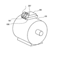
- FIG. 4 is a conceptual diagram of an invention in which an inverter and a motor described in Patent Document 1 or 2 are integrated.
- a power receiving box 100C is provided in a motor case 100 housing a three-phase AC motor (induction motor or synchronous motor).
- the motor input terminal 100T which is mounted and receives the three-phase alternating current power is attached thereto, and on the other hand, the inverter which receives the direct current from the direct current power source placed in the other part of the automobile and converts it into the three-phase alternating current
- An inverter output terminal 200T is attached to the inverter case 200.
- the connection conductor L is used to supply the three-phase AC power of the inverter from the inverter output terminal 200T to the motor input terminal 100T of the power receiving box 100C.
- the terminal block described in Patent Document 3 is for connecting an inverter output terminal and a motor input terminal, and includes an inverter housing, an inverter side terminal, a motor housing and a motor side terminal, and the motor side terminal is a motor housing. Whereas the inverter side terminal is fixed to the body, the inverter side terminal is attached to the inverter housing via a vibration absorbing member.
- the terminal block described in Patent Document 3 uses various metal materials such as a bus bar in order to ensure conduction performance.
- the rigidity of the bus bar member and terminal is high, so when assembled to a site where vibration occurs, the bus bar member and terminal will bend and bend and deform due to long-term use, resulting in a sealing performance. It has the problem of decreasing.
- the present invention has been made to solve the above problems, and is resistant to vibration generated between the motor-side connection terminal and the inverter-side connection terminal, and even if there is a large variation due to an assembly error between the motor and the inverter. It is an object of the present invention to provide a terminal block with good waterproof and oil resistance that can sufficiently exhibit a sealing effect.
- the first invention of the present application is a terminal that is interposed between a motor case and an inverter case mounted on the motor case and electrically connects the inverter output terminal and the motor input terminal.
- a base In the base, an upper base for accommodating an inverter side connection terminal connected to the inverter output terminal is fixed to the inverter case, and a lower base for accommodating a motor side connection terminal connected to the motor input terminal is provided to the motor case.
- a waterproof and elastic member is interposed between the upper base and the lower base, and the inverter side connection terminal and the motor side connection terminal are electrically connected by a flexible conductive member. It is said.
- the second invention of the present application is characterized in that, in the terminal block of the first invention, a waterproof rubber plug is interposed between the upper base and the inverter case.
- a third invention of the present application is characterized in that, in the terminal block of the first or second invention, a waterproof rubber plug is interposed between the lower base and the motor case.
- the inverter side connection terminal and the motor side connection terminal are configured as an integral terminal block. Since it is separated from the lower base that houses the side connection terminal and an elastic member is interposed between the upper base and the lower base, vibration on the motor side is difficult to be transmitted to the inverter side, and the motor side connection terminal and By connecting the inverter side connection terminal with the flexible conductive member, a terminal block resistant to vibration can be obtained.
- the elastic member interposed between the upper base and the lower base is waterproof, even if the car is submerged and water enters between the motor case and the inverter case, the upper base and the lower base The waterproof elastic member can prevent water from entering the terminal block from the fitting portion.
- the waterproof rubber plugs are interposed between the upper base and the inverter case, and between the lower base and the motor case, respectively. It will be even more certain.
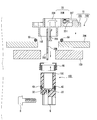
- FIG. 1 is a longitudinal sectional view of a terminal block according to the present invention.
- FIG. 2 is an exploded vertical sectional view of the terminal block of FIG.
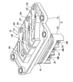
- FIG. 3 is a perspective view of a terminal block according to the present invention.
- FIG. 4 is a conceptual diagram of an invention in which an inverter and a motor described in Patent Document 1 or 2 are integrated.
- ⁇ Terminal block according to the present invention> 1 showing a longitudinal section of a terminal block according to the present invention, and FIG. 2 showing an exploded view of the terminal block of FIG. 1, 100 is a motor case, and 200 is an inverter case mounted on the motor case 100.
- Reference numeral 10 denotes a terminal block according to the present invention interposed between the motor case 100 and the inverter case 200.
- the terminal block 10 is a resin-molded container, and three systems of electric conductors 20 (inverter-side connection terminal 20T + braided wire 20H + motor-side connection terminal 20M) that feed AC three-phase current produced on the inverter side to the motor side. Is for housing.
- the terminal block 10 is composed of the upper base 10U and the lower base 10D separately.
- the upper base 10U houses the inverter side connection terminals 20T
- the lower base 10D houses the motor side connection terminals 20M.
- the inverter side connection terminal 20T and the motor side connection terminal 20M are connected by a braided wire 20H.
- the electric conductor 20 includes an inverter-side connection terminal 20T, a motor-side connection terminal 20M, and a braid in which one is connected to the inverter-side connection terminal 20T and the other is connected to the motor-side connection terminal 20M by a crimping portion 20S (FIG. 2).
- Line 20H One end of the braided wire 20H is connected to the inverter side connection terminal 20T in the upper base 10U in a horizontal state, and the other end is directed toward the lower base 10D.
- Each inverter-side connection terminal 20T and each motor-side connection terminal 20M are respectively provided with bolt through holes 20B (FIG. 3) and 20C (FIG. 2).
- the bolt through holes 20B serve as an inverter of the inverter case 200 (FIG. 4). It is passed through the output terminal 200T (FIG. 4) and fastened with a nut. Further, a bolt is passed through the bolt through hole 20C and fastened to, for example, the motor input terminal 100T (FIG. 4) of the power receiving box 100C (FIG. 4) on the motor case 100 (FIG. 4) side. A packing 30 is attached to the motor side connection terminal 20M to prevent oil leakage from the motor.
- the braided wire 20H is used here, the bus bar can be made flexible by providing a bent portion. Therefore, such a bus bar with a bent portion or a conductive rubber is used. It is also possible.
- three inverter side connection terminals 20T are arranged in a horizontally juxtaposed state via resin partitions, and a braided wire 20H is connected to each end of the inverter side connection terminal 20T. ing. Since the other end of the braided wire 20H goes from the horizontal state to the lower base 10D, the other end is in the vertical state.
- the three braided wires 20H in the vertical state pass through the long cylindrical portion 10E formed at the lower portion of the upper base 10U.
- the lower base 10D is entirely formed of a long cylindrical portion, in which three braided wires 20H and motor side connection terminals 20M that are caulked and connected to the braided wires 20H, respectively, are juxtaposed vertically via resin partitions. Arranged in a state.
- the top portion 10C (FIG. 2) of the lower base 10D is fitted into a long cylindrical portion 10E formed at the lower portion of the upper base 10U via a waterproof and elastic member 60 (described later).
- the waterproof and elastic member 60 is interposed between the upper base 10U and the lower base 10D.
- the waterproof and elastic member 60 has a long cylindrical shape with a ceiling. An opening into which the motor side connection terminal 20M and the caulking portion 20S can be inserted is formed in the ceiling, and a cross section is formed in a side surface of the long cylinder. A wave shape consisting of peaks and valleys is formed.
- the top portion 10C of the lower base 10D is inserted into the internal opening of the long cylindrical portion, and by inserting the top portion 10C into the long cylindrical portion 10E below the upper base 10U, the wave-shaped peaks of the waterproof and elastic member 60 are crushed, and the upper base Vibration absorption and waterproofing are ensured between 10U and the lower base 10D.
- the normal waterproof / elastic member is indicated by the dotted line intentionally showing the lip portion of the waterproof / elastic member 60 in a state where no external force is applied to the inner peripheral surface of the upper base 10U. 60 shows the original shape, and does not show biting into the inner peripheral surface of the upper base 10U.
- ⁇ Material of waterproof and elastic member 60 As a material of the waterproof and elastic member 60, a rubber member having excellent oil resistance can be used. Specifically, for example, acrylic rubber can be used.
- the waterproof and elastic member 60 provided at the place where the upper base 10U and the lower base 10D are separated and fitted is provided with a waterproof function, the motor case 100 and the inverter are temporarily submerged in water. Even if water enters between the case 200 and the waterproof and elastic member 60, it is possible to prevent water from entering the terminal block 10 from the fitting portion between the upper base 10U and the lower base 10D.
- a waterproof rubber plug 40 is interposed between the lower base 10D and the motor case 100, and a waterproof rubber plug 50 is interposed between the upper base 10U and the inverter case 200.
- the inverter side connection terminal and the motor side connection terminal are configured as an integrated terminal block, but according to the present invention, the inverter base connection terminal and the motor base connection terminal are separated into an upper base for storing the inverter side connection terminal and a motor base connection terminal.
- an elastic member is interposed between the upper base and the lower base, vibration on the motor side is hardly transmitted to the inverter side.
- a terminal block that is resistant to vibration is obtained by connecting the motor side connection terminal and the inverter side connection terminal with a braided wire.
- the elastic member interposed between the upper base and the lower base is waterproof, even if the car is submerged and water enters between the motor case and the inverter case, the upper base and the lower base
- the waterproof elastic member can prevent water from entering the terminal block from the fitting portion.
Landscapes
- Engineering & Computer Science (AREA)
- Power Engineering (AREA)
- Microelectronics & Electronic Packaging (AREA)
- Motor Or Generator Frames (AREA)
- Connector Housings Or Holding Contact Members (AREA)
Abstract
Description
バッテリに蓄えられた電力はインバータ装置等のインバータで変換されてモータに供給され、モータを回転し、モータの回転は車輪に伝達され、車輪を駆動する。
従来、インバータとモータは自動車の別々の場所に搭載され、インバータの端子とモータの端子はワイヤーハーネスを用いて接続していた。
これに対して、最近、バッテリから車輪までの電動駆動システムの小型化、低コスト化を目的に、インバータとモータとを一体化する構造が提案されている(特許文献1または2)。
図4は、特許文献1または2に記載のインバータとモータとを一体化する発明の概念図で、三相交流電動機(誘導電動機または同期機)を収納しているモータケース100に受電ボックス100Cが載置され、そこに三相交流電力を受電するモータ入力端子100Tが取り付けられており、一方、自動車の他部に載置されている直流電源から直流を受電して三相交流に変換するインバータのインバータケース200にインバータ出力端子200Tが取り付けられている。そして、インバータの三相交流電力をインバータ出力端子200Tから受電ボックス100Cのモータ入力端子100Tへ供給するために接続導体Lが用いられる。
図4に示される構造物は、モータケース100とインバータケース200を別々に組み立てた後に、インバータケース200をモータケース100の近傍に設置するとともに、インバータ出力端子200Tとモータ入力端子100Tを接続導体Lによって電気的に接続することにより組み立てられる。このように、インバータケース200とモータケース100は別々のモジュールとして組み立て製造され、一体化時には接続導体Lによって電気的に接続される構造なので、製造が容易で、低コスト化が可能となる。
ところがこのような構成において、運転時の車体の振動やモータ自体の振動によるインバータとモータの振動の位相差がコネクタに加わり、コネクタに破損等が生じる恐れがあった。したがって、このような振動に耐えうるコネクタの開発が必要であった。
そして、そのような振動に耐えうるコネクタとして、特許文献3記載のコネクタが開示されている。
特許文献3記載の端子台は、インバータ出力端子とモータ入力端子を接続するためのもので、インバータ筐体とインバータ側端子と、モータ筐体とモータ側端子とからなり、モータ側端子はモータ筐体に固定して取り付けられているのに対して、インバータ側端子は振動吸収部材を介してインバータ筐体に取り付けられるようにしたことを特徴とするものである。
このように一方の機器の端子がその筐体に振動吸収部材を介して取り付けられているので、一方の機器と他方の機器に位相差による振動が加わっても、その振動は振動吸収部材によって吸収されるので、コネクタ接続部に余分な負荷が加わることなく、破損等の悪影響を防ぐことができるというものである。
特許文献3記載の端子台は、導通性能を確保するため、バスバー等の金属材料を多様に使用している。しかしながら、この端子台では、バスバー部材や端子の剛性が高いため、振動の生じる部位へ組み付けるとその後の長時間の使用によってバスバー部材や端子に折れや曲がり等が発生して変形し、シール性能が低下するという課題を有している。
本発明は、上記課題を解決するためになされたもので、モータ側接続端子とインバータ側接続端子との間に生じる振動に強く、かつ、モータとインバータの組み付け誤差によるバラつきが大きくても、振動に対して充分にシール効果を発揮できる防水・防油性の良い端子台を提供することを目的としている。
さらに、アッパーベースとロアーベースとの間に介在させる弾性部材に防水性をもたせたので、車が仮に水没してモータケースとインバータケースとの間に水が浸入したとしても、アッパーベースとロアーベースの嵌合部から端子台の内部に水が浸入することが防水用弾性部材により防止できる。
本発明に係る端子台の縦断面を示した図1と、図1の端子台を分解して示した図2において、100はモータケース、200はモータケース100に載置されるインバータケースである。
10はモータケース100とインバータケース200との間に介在する本発明に係る端子台である。端子台10は樹脂成形されて成る容器で、インバータ側で作られた交流三相電流をモータ側へ給電する3系統の電気伝導体20(インバータ側接続端子20T+編組線20H+モータ側接続端子20M)を収容するためのものである。本発明により、端子台10はアッパーベース10Uとロアーベース10Dとを別体で構成し、アッパーベース10Uにはインバータ側接続端子20Tを収納し、ロアーベース10Dにはモータ側接続端子20Mを収納し、インバータ側接続端子20Tとモータ側接続端子20Mを編組線20Hで接続している。
電気伝導体20は、インバータ側接続端子20Tと、モータ側接続端子20Mと、一方がインバータ側接続端子20Tに接続され他方がカシメ部20S(図2)によってモータ側接続端子20Mに接続された編組線20Hとから構成されている。編組線20Hはアッパーベース10U内で一端がインバータ側接続端子20Tと水平状態で接続され、他端がロアーベース10D側に向かうため水平状態から垂直に下方へ曲折して延び、先端でカシメ部20Sによってモータ側接続端子20Mに接続されている。
各インバータ側接続端子20Tおよび各モータ側接続端子20Mにはそれぞれボルト貫通孔20B(図3)、20C(図2)があけられており、ボルト貫通孔20Bはインバータケース200(図4)のインバータ出力端子200T(図4)に通されてナットで締結される。
また、ボルト貫通孔20Cにはボルトが通されてモータケース100(図4)側の例えば受電ボックス100C(図4)のモータ入力端子100T(図4)へ締結される。
モータ側接続端子20Mにはモータからの油漏れ防止のため等のパッキン30が取り付けられている。
なお、ここでは編組線20Hを用いているが、バスバーに屈曲部を設けることで可撓性をもたせることができるので、このような屈曲部付きバスバーを用いたり、あるいは導電性ゴムを用いたりすることも可能である。
アッパーベース10U側には、3本のインバータ側接続端子20Tがそれぞれ樹脂の隔壁を介して水平並置状態に配設されており、インバータ側接続端子20Tの各端部にそれぞれ編組線20Hが接続されている。編組線20Hの他端は水平状態から下方のロアーベース10Dに向かうため垂直状態になる。垂直状態の編組線20Hの3本はアッパーベース10Uの下部に形成された長円筒部10Eの中を通過する。
ロアーベース10Dは全体が長円筒部で形成され、この中に3本の編組線20Hと、これら編組線20Hとそれぞれかしめ接続されるモータ側接続端子20Mが、それぞれ樹脂の隔壁を介して垂直並置状態に配設されている。ロアーベース10Dの頂部10C(図2)はアッパーベース10Uの下部に形成された長円筒部10Eの中に防水兼弾性部材60(後述)を介して嵌合している。
また、本発明によって、アッパーベース10Uとロアーベース10Dとの間に防水兼弾性部材60を介在させている。防水兼弾性部材60は、天井付き長円筒状をしており、天井部にはモータ側接続端子20Mとカシメ部20Sとが挿入できる開口が形成されており、長円筒の側面部には断面で見て山と谷から成る波形状が形成されている。長円筒部の内部開口にロアーベース10Dの頂部10Cが挿入され、これをアッパーベース10Uの下部の長円筒部10Eに挿入することで防水兼弾性部材60の波形状の山が潰れて、アッパーベース10Uとロアーベース10Dとの間に振動吸収と防水とが確保される。
なお、図1の防水兼弾性部材60の表示では、アッパーベース10Uの内周面により外力が加わっていない状態の防水兼弾性部材60のリップ部をわざと点線で示すことで通常の防水兼弾性部材60の原形を示しているのであって、アッパーベース10Uの内周面への食い込みを示しているものではない。
防水兼弾性部材60の材料としては、耐油性に優れたゴム部材を用いることができ、具体的には、例えばアクリルゴムが挙げられる。
モータ側の振動でロアーベース10Dが図の矢印方向(図1)に動いても、このような防水兼弾性部材60をここに使用することで、防水兼弾性部材60の弾性部材が振動を吸収し、別体のアッパーベース10Uのインバータ側に振動が伝わり難くなる。
しかも、アッパーベース10Uとロアーベース10Dの間を従来のバスバーではなくて、可撓性の編組線20Hで接続したのでインバータ側に振動がさらに伝わり難くなる。
また、アッパーベース10Uとロアーベース10Dとを分離してかつ嵌合させた箇所に配設した防水兼弾性部材60に防水機能を持たせているので、車が仮に水没してモータケース100とインバータケース200との間に水が浸入したとしても、アッパーベース10Uとロアーベース10Dの嵌合部から端子台10の内部に水が浸入することが防水兼弾性部材60により防止できる。
さらに、ロアーベース10Dとモータケース100との間に防水用ゴム栓40を介在させ、また、アッパーベース10Uとインバータケース200との間に防水用ゴム栓50を介在させている。このようにすることで、端子台10の内部に水が浸入する恐れが一層防止できる。
従来インバータ側接続端子とモータ側接続端子を一体の端子台で構成していたのを、本発明によって、インバータ側接続端子を収納するアッパーベースとモータ側接続端子を収納するロアーベースとに分離し、かつアッパーベースとロアーベースとの間に弾性部材を介在させたので、モータ側の振動がインバータ側に伝わり難くなる。
しかも、モータ側接続端子とインバータ側接続端子とを編組線で接続したことで、振動に強い端子台が得られる。さらに、アッパーベースとロアーベースとの間に介在させる弾性部材に防水性をもたせたので、車が仮に水没してモータケースとインバータケースとの間に水が浸入したとしても、アッパーベースとロアーベースの嵌合部から端子台の内部に水が浸入することが防水用弾性部材により防止できる。
10U アッパーベース
10E 長円筒部
10D ロアーベース
10C ロアーベースの頂部
20 電気伝導体
20M モータ側接続端子
20H 編組線
20S カシメ部
20T インバータ側接続端子
20B、20C ボルト貫通孔
30 パッキン
40 防水用ゴム栓
50 防水用ゴム栓
60 防水兼弾性部材
100 モータケース
100C 受電ボックス
100T モータ入力端子
200 インバータケース
200T インバータ出力端子
Claims (3)
- モータケースと前記モータケースに載置されるインバータケースとの間に介在してインバータ出力端子とモータ入力端子とを電気的に接続する端子台において、
前記インバータ出力端子と接続されるインバータ側接続端子を収納するアッパーベースが前記インバータケースに固定され、
前記モータ入力端子と接続されるモータ側接続端子を収納するロアーベースが前記モータケースに固定され、
前記アッパーベースと前記ロアーベースとの間に防水兼弾性部材を介在させ、かつ前記インバータ側接続端子と前記モータ側接続端子とを可撓性導電部材で電気的に接続したことを特徴とする端子台。 - 前記アッパーベースと前記インバータケースとの間に防水用ゴム栓を介在させたことを特徴とする請求項1記載の端子台。
- 前記ロアーベースと前記モータケースとの間に防水用ゴム栓を介在させたことを特徴とする請求項1または2記載の端子台。
Priority Applications (4)
| Application Number | Priority Date | Filing Date | Title |
|---|---|---|---|
| CN201180012575.XA CN102792566B (zh) | 2010-03-05 | 2011-03-04 | 安装在电动机壳中的逆变器端子块 |
| US13/581,907 US9343941B2 (en) | 2010-03-05 | 2011-03-04 | Inverter terminal block installed in motor case |
| EP11750835.8A EP2544340B1 (en) | 2010-03-05 | 2011-03-04 | Inverter terminal block disposed on motor case |
| US15/098,359 US10523090B2 (en) | 2010-03-05 | 2016-04-14 | Inverter terminal block installed in a motor case |
Applications Claiming Priority (2)
| Application Number | Priority Date | Filing Date | Title |
|---|---|---|---|
| JP2010049272A JP5721332B2 (ja) | 2010-03-05 | 2010-03-05 | モータケースに設置されたインバータ端子台 |
| JP2010-049272 | 2010-03-05 |
Related Child Applications (2)
| Application Number | Title | Priority Date | Filing Date |
|---|---|---|---|
| US13/581,907 A-371-Of-International US9343941B2 (en) | 2010-03-05 | 2011-03-04 | Inverter terminal block installed in motor case |
| US15/098,359 Continuation US10523090B2 (en) | 2010-03-05 | 2016-04-14 | Inverter terminal block installed in a motor case |
Publications (1)
| Publication Number | Publication Date |
|---|---|
| WO2011108726A1 true WO2011108726A1 (ja) | 2011-09-09 |
Family
ID=44542370
Family Applications (1)
| Application Number | Title | Priority Date | Filing Date |
|---|---|---|---|
| PCT/JP2011/055130 Ceased WO2011108726A1 (ja) | 2010-03-05 | 2011-03-04 | モータケースに設置されたインバータ端子台 |
Country Status (5)
| Country | Link |
|---|---|
| US (2) | US9343941B2 (ja) |
| EP (1) | EP2544340B1 (ja) |
| JP (1) | JP5721332B2 (ja) |
| CN (1) | CN102792566B (ja) |
| WO (1) | WO2011108726A1 (ja) |
Cited By (2)
| Publication number | Priority date | Publication date | Assignee | Title |
|---|---|---|---|---|
| JP2015082464A (ja) * | 2013-10-24 | 2015-04-27 | 住友電装株式会社 | シールドコネクタ |
| WO2016121525A1 (ja) * | 2015-01-28 | 2016-08-04 | 住友電装株式会社 | 機器用コネクタ |
Families Citing this family (56)
| Publication number | Priority date | Publication date | Assignee | Title |
|---|---|---|---|---|
| EP2498383B1 (en) * | 2009-11-06 | 2020-02-12 | Yazaki Corporation | Inverter terminal block provided to motor case |
| JP6372974B2 (ja) * | 2013-04-26 | 2018-08-15 | 矢崎総業株式会社 | コネクタ |
| JP5979445B2 (ja) * | 2013-05-30 | 2016-08-24 | 株式会社オートネットワーク技術研究所 | 端子台 |
| JP6024985B2 (ja) * | 2013-05-30 | 2016-11-16 | 株式会社オートネットワーク技術研究所 | 端子台 |
| JP6024986B2 (ja) * | 2013-05-30 | 2016-11-16 | 株式会社オートネットワーク技術研究所 | 端子台 |
| JP5973957B2 (ja) * | 2013-06-07 | 2016-08-23 | 本田技研工業株式会社 | 接続ユニット |
| JP6032164B2 (ja) * | 2013-09-18 | 2016-11-24 | 住友電装株式会社 | 機器用コネクタ |
| JP5967063B2 (ja) | 2013-12-13 | 2016-08-10 | 株式会社オートネットワーク技術研究所 | コネクタ |
| JP6135502B2 (ja) | 2013-12-26 | 2017-05-31 | 株式会社オートネットワーク技術研究所 | コネクタ |
| JP2015133866A (ja) * | 2014-01-15 | 2015-07-23 | トヨタ自動車株式会社 | 接続構造 |
| WO2016035476A1 (ja) * | 2014-09-02 | 2016-03-10 | アイシン・エィ・ダブリュ株式会社 | 端子台 |
| KR102311636B1 (ko) * | 2014-11-10 | 2021-10-12 | 현대모비스 주식회사 | 고전압 직체결 커넥터 및 그 연결구조 |
| JP6443081B2 (ja) * | 2015-01-28 | 2018-12-26 | 住友電装株式会社 | コネクタ装置 |
| JP6545529B2 (ja) * | 2015-05-26 | 2019-07-17 | 住友電装株式会社 | 防水コネクタ |
| JP6520425B2 (ja) * | 2015-06-08 | 2019-05-29 | 株式会社オートネットワーク技術研究所 | 機器用弾性シールド部材 |
| DE102015213439A1 (de) * | 2015-07-17 | 2017-01-19 | Zf Friedrichshafen Ag | Leistungsanschluss für ein elektrisches Gerät, insbesondere für eine elektrische Maschine zum Antreiben eines Kraftfahrzeuges |
| JP6271611B2 (ja) * | 2016-02-01 | 2018-01-31 | 本田技研工業株式会社 | バスバー端子、バスバー端子接続構造及びバスバー端子接続方法 |
| JP2017208193A (ja) * | 2016-05-17 | 2017-11-24 | 日本圧着端子製造株式会社 | 防水コネクタ |
| DE112017003622T5 (de) * | 2016-07-20 | 2019-04-11 | Nidec Corporation | Motor |
| KR102210887B1 (ko) | 2016-08-01 | 2021-02-02 | 삼성에스디아이 주식회사 | 배터리 모듈 |
| US10374211B2 (en) | 2016-09-12 | 2019-08-06 | Cps Technology Holdings Llc | System and method for battery modules having terminal block assemblies with drainage channels |
| CN110024230B (zh) * | 2016-11-22 | 2021-07-09 | 株式会社荏原制作所 | 水中马达及防水连接器 |
| JP2018147791A (ja) | 2017-03-07 | 2018-09-20 | 株式会社オートネットワーク技術研究所 | 電気機器用端末装置及び電気機器用端末装置の製造方法 |
| DE102017207215A1 (de) * | 2017-04-28 | 2018-10-31 | Zf Friedrichshafen Ag | Anschlusseinrichtung |
| FR3066864B1 (fr) * | 2017-05-23 | 2019-12-13 | Renault S.A.S | Machine electrique comprenant un bornier de raccordement electrique |
| JP6527909B2 (ja) * | 2017-06-02 | 2019-06-05 | 矢崎総業株式会社 | コネクタ設置構造及び端子台 |
| JP6709513B2 (ja) * | 2017-07-04 | 2020-06-17 | 住友電装株式会社 | 端子台 |
| JP6843264B2 (ja) * | 2017-10-19 | 2021-03-17 | 三菱電機株式会社 | 防水型コネクタおよびその組立方法 |
| JP7006206B2 (ja) * | 2017-12-05 | 2022-01-24 | 住友電装株式会社 | コネクタ組付体 |
| DE102018206293A1 (de) * | 2018-04-24 | 2019-10-24 | Zf Friedrichshafen Ag | Schnittstellenvorrichtung für ein Fahrzeug, Antriebssystem für ein Fahrzeug und Verfahren zum Montieren eines Antriebssystems für ein Fahrzeug |
| WO2019208445A1 (ja) * | 2018-04-25 | 2019-10-31 | 日本電産株式会社 | モータユニットおよびモータユニットの製造方法 |
| JP7019147B2 (ja) * | 2018-05-09 | 2022-02-15 | 日本圧着端子製造株式会社 | 防水コネクタ及び機器ケースの防水構造 |
| DE102018218163A1 (de) * | 2018-10-24 | 2020-04-30 | Zf Friedrichshafen Ag | Schnittstellenmodul, Wechselrichter und Fahrzeug |
| JP6978400B2 (ja) * | 2018-12-11 | 2021-12-08 | 矢崎総業株式会社 | 端子台、及び、機器同士の電気接続構造 |
| JP6905544B2 (ja) * | 2019-01-10 | 2021-07-21 | 矢崎総業株式会社 | 防水コネクタ及びコネクタ付き機器 |
| EP3921926B1 (en) * | 2019-02-08 | 2025-01-15 | GKN Automotive Limited | Connector assembly and a method for electrically connecting an inverter busbar to an electrical connector of a drive unit and such a drive unit |
| JP2020141430A (ja) * | 2019-02-26 | 2020-09-03 | 本田技研工業株式会社 | パワーコントロールユニットの給電接続部構造 |
| JP2020155392A (ja) * | 2019-03-22 | 2020-09-24 | 株式会社オートネットワーク技術研究所 | コネクタ付きケース、コネクタ付きワイヤーハーネス、及びエンジンコントロールユニット |
| CN113615051B (zh) * | 2019-03-27 | 2024-06-25 | 株式会社Ihi | 逆变器一体型气体供给装置 |
| JP7005119B2 (ja) * | 2019-07-29 | 2022-01-21 | 矢崎総業株式会社 | コネクタ |
| JP7005118B2 (ja) * | 2019-07-29 | 2022-01-21 | 矢崎総業株式会社 | コネクタ |
| JP7041101B2 (ja) * | 2019-08-07 | 2022-03-23 | 矢崎総業株式会社 | コネクタ |
| JP7268542B2 (ja) * | 2019-08-29 | 2023-05-08 | 株式会社プロテリアル | 回転電機用配線部材の配置構造 |
| BE1027895B1 (nl) * | 2019-12-20 | 2021-07-26 | Punch Powertrain Psa E Trans Nv | Aandrijfeenheid voor een voertuig |
| FR3107794B1 (fr) * | 2020-02-27 | 2025-02-21 | Valeo Equip Electr Moteur | Ensemble comportant une machine électrique et un connecteur de signal découplés |
| DE102020206124A1 (de) * | 2020-05-14 | 2021-11-18 | Volkswagen Aktiengesellschaft | Kontaktvorrichtung und Elektromotor |
| EP3944469B1 (en) * | 2020-07-22 | 2024-09-18 | Mahle International GmbH | Electric motor |
| US11764641B2 (en) | 2020-11-13 | 2023-09-19 | Regal Beloit America, Inc. | Terminal box assembly for an electric motor assembly |
| JP7630300B2 (ja) * | 2021-03-01 | 2025-02-17 | 古河電気工業株式会社 | 端子台 |
| JP2022153953A (ja) * | 2021-03-30 | 2022-10-13 | 日本電産株式会社 | コネクタ、駆動モータモジュール及び車両 |
| JP7680248B2 (ja) * | 2021-04-09 | 2025-05-20 | 古河電気工業株式会社 | 端子台 |
| JP7480747B2 (ja) | 2021-05-17 | 2024-05-10 | 株式会社オートネットワーク技術研究所 | 端子台ユニット |
| JP7393402B2 (ja) * | 2021-09-16 | 2023-12-06 | 矢崎総業株式会社 | 端子台 |
| JP7389848B2 (ja) * | 2022-04-28 | 2023-11-30 | 本田技研工業株式会社 | 駆動ユニット |
| US12606029B2 (en) * | 2023-09-12 | 2026-04-21 | BorgWarner US Technologies LLC | Systems for molding metal sheet into inverter for improving emc performance |
| US20250239908A1 (en) * | 2024-01-18 | 2025-07-24 | Black & Decker Inc. | Sealed electric motor |
Citations (5)
| Publication number | Priority date | Publication date | Assignee | Title |
|---|---|---|---|---|
| JPH0459661U (ja) * | 1990-09-28 | 1992-05-21 | ||
| JPH05219607A (ja) | 1992-02-07 | 1993-08-27 | Fuji Electric Co Ltd | 電気自動車の駆動システム |
| JP2004312853A (ja) | 2003-04-04 | 2004-11-04 | Hitachi Ltd | 車両駆動ユニット及び車両駆動装置 |
| JP2007280913A (ja) | 2006-03-15 | 2007-10-25 | Hitachi Cable Ltd | コネクタ構造 |
| JP2010049272A (ja) | 2002-06-13 | 2010-03-04 | E Ink Corp | 電気光学表示装置の駆動の方法 |
Family Cites Families (37)
| Publication number | Priority date | Publication date | Assignee | Title |
|---|---|---|---|---|
| US4720157A (en) * | 1986-10-30 | 1988-01-19 | General Motors Corporation | Electrical connector having resilient contact means |
| JPH04136881U (ja) | 1991-06-12 | 1992-12-21 | 藤倉電線株式会社 | コネクタロツク機構 |
| US5517401A (en) | 1992-02-07 | 1996-05-14 | Fuji Electric Co., Ltd. | Three level pulse width modulated inverter for an electric vehicle |
| JPH0626184U (ja) | 1992-07-31 | 1994-04-08 | 株式会社井上製作所 | 可撓性接続端子 |
| JPH07201406A (ja) * | 1993-12-28 | 1995-08-04 | Yazaki Corp | 防水ゴム栓 |
| DE4411784C2 (de) * | 1994-04-06 | 1998-06-18 | Pfisterer Elektrotech Karl | Verbindungssystem zum Anschließen von isolierten Kabeln an elektrische Geräte |
| JP3241994B2 (ja) * | 1995-07-03 | 2001-12-25 | 株式会社荏原製作所 | 水中モータ及び防水コネクタ |
| JP3064889B2 (ja) | 1995-11-10 | 2000-07-12 | 住友電装株式会社 | 防水コネクタ |
| JPH09147963A (ja) | 1995-11-24 | 1997-06-06 | Yazaki Corp | コネクタ防水取付構造 |
| JPH11265755A (ja) * | 1998-03-16 | 1999-09-28 | Harness Syst Tech Res Ltd | 基板用可動コネクタ |
| JP3451206B2 (ja) * | 1998-11-05 | 2003-09-29 | 住友電装株式会社 | 基板用コネクタ |
| JP3893815B2 (ja) * | 1999-10-18 | 2007-03-14 | アイシン・エィ・ダブリュ株式会社 | 車両駆動装置 |
| JP2001155817A (ja) | 1999-11-26 | 2001-06-08 | Sumitomo Wiring Syst Ltd | 防水コネクタ |
| JP3434767B2 (ja) * | 2000-02-02 | 2003-08-11 | エクセン株式会社 | 振動モータのケーブル取付部防水装置 |
| JP3877139B2 (ja) | 2001-10-01 | 2007-02-07 | 矢崎総業株式会社 | 防水性を備えた電磁波シールド構造 |
| JP2003157722A (ja) * | 2001-11-22 | 2003-05-30 | Auto Network Gijutsu Kenkyusho:Kk | 配線材及びそれを備えた電機機器ユニット |
| JP2004215348A (ja) | 2002-12-27 | 2004-07-29 | Aisin Aw Co Ltd | 電動駆動装置制御ユニット部の防振装置 |
| JP2004327169A (ja) | 2003-04-23 | 2004-11-18 | Yazaki Corp | パッキンとパッキンを備えたコネクタ |
| US7197892B2 (en) * | 2003-06-11 | 2007-04-03 | Denso Corporation | Encapsulated electrically driven compressor |
| JP2005229755A (ja) * | 2004-02-13 | 2005-08-25 | Toyota Motor Corp | モータモジュール |
| JP4559747B2 (ja) * | 2004-02-13 | 2010-10-13 | トヨタ自動車株式会社 | モータモジュール |
| JP2005229753A (ja) * | 2004-02-13 | 2005-08-25 | Toyota Motor Corp | モータモジュール |
| JP4317483B2 (ja) * | 2004-04-22 | 2009-08-19 | 株式会社オートネットワーク技術研究所 | 機器用コネクタ |
| JP4473644B2 (ja) * | 2004-05-20 | 2010-06-02 | 矢崎総業株式会社 | モータの防水構造 |
| JP2006080215A (ja) * | 2004-09-08 | 2006-03-23 | Nissan Motor Co Ltd | 車両用パワー・エレクトロニクス・システムとそのノイズ抑制方法 |
| JP5002971B2 (ja) * | 2005-02-17 | 2012-08-15 | トヨタ自動車株式会社 | バスバー、電気回路システム |
| JP2007080737A (ja) * | 2005-09-15 | 2007-03-29 | Sumitomo Wiring Syst Ltd | コネクタ装置 |
| JP2007311123A (ja) | 2006-05-17 | 2007-11-29 | Toyota Motor Corp | 電気機器と給電端子部との接続構造および車両 |
| JP2008243566A (ja) | 2007-03-27 | 2008-10-09 | Hirose Electric Co Ltd | 電気コネクタ |
| JP4967817B2 (ja) | 2007-05-29 | 2012-07-04 | トヨタ自動車株式会社 | 回転電機用端子台 |
| JP5059527B2 (ja) | 2007-09-12 | 2012-10-24 | 株式会社オートネットワーク技術研究所 | 中継コネクタ |
| JP2009142038A (ja) * | 2007-12-05 | 2009-06-25 | Toyota Motor Corp | 車両用駆動装置 |
| JP2009195080A (ja) * | 2008-02-18 | 2009-08-27 | Toyota Motor Corp | 回転電機の電気接続構造 |
| KR101435209B1 (ko) * | 2008-08-05 | 2014-08-28 | 현대자동차주식회사 | 단자연결 조립체 |
| US8134268B2 (en) * | 2009-01-09 | 2012-03-13 | Honeywell International, Inc. | Wound field electrical machine flat braided wire main rotor crossover assembly |
| JP5585106B2 (ja) * | 2010-02-08 | 2014-09-10 | 株式会社オートネットワーク技術研究所 | コネクタ装置 |
| US20120156909A1 (en) * | 2010-12-17 | 2012-06-21 | Tyco Electronics Corporation | Power connector assembly |
-
2010
- 2010-03-05 JP JP2010049272A patent/JP5721332B2/ja active Active
-
2011
- 2011-03-04 EP EP11750835.8A patent/EP2544340B1/en active Active
- 2011-03-04 WO PCT/JP2011/055130 patent/WO2011108726A1/ja not_active Ceased
- 2011-03-04 CN CN201180012575.XA patent/CN102792566B/zh active Active
- 2011-03-04 US US13/581,907 patent/US9343941B2/en active Active
-
2016
- 2016-04-14 US US15/098,359 patent/US10523090B2/en active Active
Patent Citations (5)
| Publication number | Priority date | Publication date | Assignee | Title |
|---|---|---|---|---|
| JPH0459661U (ja) * | 1990-09-28 | 1992-05-21 | ||
| JPH05219607A (ja) | 1992-02-07 | 1993-08-27 | Fuji Electric Co Ltd | 電気自動車の駆動システム |
| JP2010049272A (ja) | 2002-06-13 | 2010-03-04 | E Ink Corp | 電気光学表示装置の駆動の方法 |
| JP2004312853A (ja) | 2003-04-04 | 2004-11-04 | Hitachi Ltd | 車両駆動ユニット及び車両駆動装置 |
| JP2007280913A (ja) | 2006-03-15 | 2007-10-25 | Hitachi Cable Ltd | コネクタ構造 |
Non-Patent Citations (1)
| Title |
|---|
| See also references of EP2544340A4 |
Cited By (4)
| Publication number | Priority date | Publication date | Assignee | Title |
|---|---|---|---|---|
| JP2015082464A (ja) * | 2013-10-24 | 2015-04-27 | 住友電装株式会社 | シールドコネクタ |
| WO2016121525A1 (ja) * | 2015-01-28 | 2016-08-04 | 住友電装株式会社 | 機器用コネクタ |
| JP2016139541A (ja) * | 2015-01-28 | 2016-08-04 | 住友電装株式会社 | 機器用コネクタ |
| US9966715B2 (en) | 2015-01-28 | 2018-05-08 | Sumitomo Wiring Systems, Ltd. | Device connector |
Also Published As
| Publication number | Publication date |
|---|---|
| US9343941B2 (en) | 2016-05-17 |
| US10523090B2 (en) | 2019-12-31 |
| JP5721332B2 (ja) | 2015-05-20 |
| EP2544340B1 (en) | 2021-07-21 |
| JP2011187224A (ja) | 2011-09-22 |
| US20160226347A1 (en) | 2016-08-04 |
| EP2544340A1 (en) | 2013-01-09 |
| EP2544340A4 (en) | 2017-01-18 |
| CN102792566B (zh) | 2015-07-29 |
| CN102792566A (zh) | 2012-11-21 |
| US20120319513A1 (en) | 2012-12-20 |
Similar Documents
| Publication | Publication Date | Title |
|---|---|---|
| JP5721332B2 (ja) | モータケースに設置されたインバータ端子台 | |
| JP5410542B2 (ja) | モータケースに設置されたインバータ端子台 | |
| JP5410543B2 (ja) | インバータ端子台 | |
| US8993890B2 (en) | Electric cable and electric connector | |
| CN104619549A (zh) | 搭载于电动车辆的电力转换装置 | |
| JP5208578B2 (ja) | モータユニットおよびモータユニットの製造方法 | |
| JP2012084513A (ja) | 導電路構造及びワイヤハーネス | |
| JP5981573B2 (ja) | 端子台 | |
| JP5966024B2 (ja) | 端子台 | |
| JP2017139935A (ja) | 電力変換装置 | |
| JP5970568B2 (ja) | 端子台の組み付け方法 | |
| CN102468717B (zh) | 旋转电机 | |
| CN102638123A (zh) | 旋转电机 | |
| JP2024043247A (ja) | 車両用モータ駆動装置 | |
| CN220923821U (zh) | 增程器以及机动设备 | |
| JP2004364356A (ja) | 車両用インバータ装置 | |
| JP2019024041A (ja) | 車載機器 | |
| JP2017103842A (ja) | インバータ一体型モータの接続構造及びインバータ一体型モータ | |
| JP2013149374A (ja) | 電線コネクタ固定構造 | |
| JP2012146580A (ja) | 電力ケーブルの絶縁ブッシュ |
Legal Events
| Date | Code | Title | Description |
|---|---|---|---|
| WWE | Wipo information: entry into national phase |
Ref document number: 201180012575.X Country of ref document: CN |
|
| 121 | Ep: the epo has been informed by wipo that ep was designated in this application |
Ref document number: 11750835 Country of ref document: EP Kind code of ref document: A1 |
|
| WWE | Wipo information: entry into national phase |
Ref document number: 13581907 Country of ref document: US |
|
| WWE | Wipo information: entry into national phase |
Ref document number: 2011750835 Country of ref document: EP |
|
| WWE | Wipo information: entry into national phase |
Ref document number: 7618/CHENP/2012 Country of ref document: IN |
|
| NENP | Non-entry into the national phase |
Ref country code: DE |